WO2024252529A1 - 劣化判別装置および劣化判別方法 - Google Patents
劣化判別装置および劣化判別方法 Download PDFInfo
- Publication number
- WO2024252529A1 WO2024252529A1 PCT/JP2023/021051 JP2023021051W WO2024252529A1 WO 2024252529 A1 WO2024252529 A1 WO 2024252529A1 JP 2023021051 W JP2023021051 W JP 2023021051W WO 2024252529 A1 WO2024252529 A1 WO 2024252529A1
- Authority
- WO
- WIPO (PCT)
- Prior art keywords
- voltage
- constant
- deterioration determination
- voltage power
- power supply
- Prior art date
- Legal status (The legal status is an assumption and is not a legal conclusion. Google has not performed a legal analysis and makes no representation as to the accuracy of the status listed.)
- Ceased
Links
Images




Classifications
-
- H—ELECTRICITY
- H02—GENERATION; CONVERSION OR DISTRIBUTION OF ELECTRIC POWER
- H02M—APPARATUS FOR CONVERSION BETWEEN AC AND AC, BETWEEN AC AND DC, OR BETWEEN DC AND DC, AND FOR USE WITH MAINS OR SIMILAR POWER SUPPLY SYSTEMS; CONVERSION OF DC OR AC INPUT POWER INTO SURGE OUTPUT POWER; CONTROL OR REGULATION THEREOF
- H02M1/00—Details of apparatus for conversion
- H02M1/36—Means for starting or stopping converters
-
- H—ELECTRICITY
- H02—GENERATION; CONVERSION OR DISTRIBUTION OF ELECTRIC POWER
- H02M—APPARATUS FOR CONVERSION BETWEEN AC AND AC, BETWEEN AC AND DC, OR BETWEEN DC AND DC, AND FOR USE WITH MAINS OR SIMILAR POWER SUPPLY SYSTEMS; CONVERSION OF DC OR AC INPUT POWER INTO SURGE OUTPUT POWER; CONTROL OR REGULATION THEREOF
- H02M1/00—Details of apparatus for conversion
- H02M1/32—Means for protecting converters other than automatic disconnection
-
- H—ELECTRICITY
- H02—GENERATION; CONVERSION OR DISTRIBUTION OF ELECTRIC POWER
- H02M—APPARATUS FOR CONVERSION BETWEEN AC AND AC, BETWEEN AC AND DC, OR BETWEEN DC AND DC, AND FOR USE WITH MAINS OR SIMILAR POWER SUPPLY SYSTEMS; CONVERSION OF DC OR AC INPUT POWER INTO SURGE OUTPUT POWER; CONTROL OR REGULATION THEREOF
- H02M7/00—Conversion of AC power input into DC power output; Conversion of DC power input into AC power output
- H02M7/02—Conversion of AC power input into DC power output without possibility of reversal
Definitions
- This disclosure relates to a deterioration determination device and a deterioration determination method.
- Patent Document 1 discloses an example of a degradation determination device that determines whether or not a constant-voltage power supply has deteriorated in order to ensure stable operation of the electronic devices.
- the degradation detection device disclosed in Patent Document 1 detects degradation of a low-voltage power supply device from the timing when the input voltage of the low-voltage power supply device to be detected rises, the timing when the charging voltage of a smoothing capacitor provided in the low-voltage power supply device rises to a predetermined voltage, and the timing when the output voltage of the low-voltage power supply device rises.
- the deterioration detection device disclosed in Patent Document 1 needs to detect and analyze the voltage of the smoothing capacitor inside the low-voltage power supply device being detected, in addition to the input and output of the low-voltage power supply device being detected, which makes the method of determining deterioration complicated and the structure of the deterioration detection device complex.
- This disclosure has been made in consideration of the above circumstances, and aims to provide a degradation determination device and degradation determination method that can determine the presence or absence of degradation in a constant-voltage power supply with a simple configuration.
- the deterioration determination device disclosed herein is a deterioration determination device that determines whether or not a constant-voltage power supply that outputs an operating voltage for performing a switching operation of an electronic device having a switching element has deteriorated, and includes a signal processing unit and a deterioration determination unit.
- the signal processing unit generates voltage data based on the amplitude of the output voltage from the output voltage of the constant-voltage power supply.
- the deterioration determination unit obtains the start-up time of the constant-voltage power supply from the start-up command for the electronic device and the voltage data, and determines whether or not the constant-voltage power supply has deteriorated from the start-up time.
- the degradation determination device determines the startup time of a constant-voltage power supply from a startup command for an electronic device and voltage data indicating the amplitude of the output voltage of the constant-voltage power supply, and determines whether or not the constant-voltage power supply has deteriorated from the startup time. Because the degradation determination device does not need to obtain electrical physical quantities for the elements inside the electronic device, a degradation determination device that can determine whether or not a constant-voltage power supply has deteriorated can be obtained with a simple configuration.
- FIG. 1 is a diagram showing a hardware configuration of a deterioration determination device according to a first embodiment
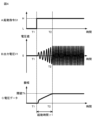
- FIG. 2 is a diagram showing an example of the relationship between a start-up command, an output voltage, and a start-up time of a constant-voltage power supply that is a deterioration determination target of the deterioration determination device according to the first embodiment; Block diagram of a deterioration determination device according to a second embodiment. Block diagram of a deterioration determination device according to a third embodiment.
- FIG. 2 is a block diagram of a modification of the deterioration determination device according to the embodiment
- FIG. 13 is a diagram showing a modification of the hardware configuration of the deterioration determination device according to the embodiment;
- An example of an electronic device having a switching element is a power conversion device mounted on a railway vehicle.
- a deterioration determination device according to a first embodiment will be described below using as an example a deterioration determination device that determines whether or not a constant-voltage power supply that outputs an operating voltage for performing a switching operation of a switching element in a power conversion device.
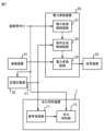
- the deterioration determination device 1 according to the first embodiment shown in FIG. 1 determines whether or not a constant-voltage power supply 32 that outputs an operating voltage to a power conversion device 20 has deteriorated.
- the power conversion device 20 starts operating in response to the start-up command S1, converts the power supplied from the current collector 31 into power to be supplied to the load device 33, and supplies the converted power to the load device 33.
- the power conversion device 20 includes a power conversion control circuit 21 that generates a plurality of gate signals for controlling a plurality of switching elements, and a power conversion circuit 22 that has a plurality of switching elements and converts the power supplied from the current collector 31 into power to be supplied to the load device 33.
- the power conversion control circuit 21 starts operation and generates a gate signal in response to a start command S1 supplied from the cab.
- the start command S1 is a signal that instructs the start of the power conversion device 20. Starting up the power conversion device 20 includes restarting it.
- the start command S1 is, for example, a signal that becomes H (high) level a certain time after a switch that instructs the start of operation of the railway vehicle is operated, and becomes L (low) level when the operation of the railway vehicle ends.
- the switch that instructs the start of operation of the railway vehicle is, for example, a start switch provided in the cab that raises a pantograph, which is a type of current collector 31, and abuts the pantograph against an overhead line, which is a type of power supply line.
- Each switching element of the power conversion circuit 22 is controlled to be turned on and off by a gate signal output by the power conversion control circuit 21, and performs a switching operation.
- the operating voltage output by the constant voltage power supply 32 enables each switching element of the power conversion circuit 22 to perform a switching operation.
- the power conversion circuit 22 converts the power supplied from the current collector 31 into power to be supplied to the load device 33, and supplies the converted power to the load device 33.
- the power conversion circuit 22 has, for example, an inverter circuit that converts DC power supplied from the current collector 31 into AC power and supplies the AC power to the load device 33.
- the current collector 31 is, for example, a pantograph or a collector shoe, and acquires power supplied from a substation via a power supply line.
- the current collector 31 supplies the acquired power to the power conversion circuit 22 provided in the power conversion device 20.
- the load device 33 is an electronic device that consumes power, such as lighting equipment, air conditioning equipment, and electric motors that are installed in railway vehicles.
- the constant voltage power supply 32 starts operating when the power conversion device 20 is started.
- the constant voltage power supply 32 starts operating and outputs an operating voltage, which is an AC voltage for performing the switching operation of the switching element, to the power conversion circuit 22 provided in the power conversion device 20.
- the deterioration determination device 1 determines whether the constant-voltage power supply 32 has deteriorated.
- the deterioration determination device 1 has a signal processing unit 11 that generates voltage data based on the amplitude of the output voltage V1 from the output voltage V1 of the constant-voltage power supply 32, and a deterioration determination unit 12 that obtains the start-up time of the constant-voltage power supply 32 from the start-up command S1 and the voltage data, and determines whether the constant-voltage power supply 32 has deteriorated from the start-up time.
- the signal processing unit 11 performs signal processing on the output voltage V1 of the constant-voltage power supply to generate voltage data based on the amplitude of the output voltage.
- the signal processing unit 11 performs filtering based on an LPF (Low Pass Filter) on waveform data indicating the output voltage V1 of the constant-voltage power supply to generate analog domain envelope data indicating the envelope of the waveform data.
- the signal processing unit 11 performs A/D (Analog/Digital) conversion on the analog domain envelope data to generate digital domain voltage data.
- the signal processing unit 11 sends the generated voltage data to the degradation determination unit 12.
- the deterioration determination unit 12 obtains a start-up command S1 for the power conversion device 20 and obtains voltage data from the signal processing unit 11.
- the deterioration determination unit 12 determines the start-up time of the constant-voltage power supply 32 from the start-up command S1 for the power conversion device 20 and the voltage data.
- the deterioration determination unit 12 determines the start-up time from when the start-up command S1 instructs the power conversion device 20 to start up until the amplitude indicated by the voltage data reaches a threshold value.
- the threshold value is determined according to the rated operating voltage required for the power conversion device 20 to perform the switching operation of multiple switching elements.
- the deterioration determination unit 12 determines whether the constant-voltage power supply 32 has deteriorated from the startup time of the constant-voltage power supply 32.
- the deterioration determination unit 12 outputs the determination result to an output device, external equipment, etc. (not shown).
- an output device having a display screen can display the determination result on the screen, making it possible to prompt maintenance work on the constant-voltage power supply 32.
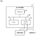
- the hardware configuration of the deterioration determination device 1 having the above configuration is shown in Figure 2.
- the deterioration determination device 1 includes a processor 91, a memory 92, and an interface 93.
- the processor 91, the memory 92, and the interface 93 are connected to each other via a bus 90.
- the functions of each part of the deterioration determination device 1 are realized by software, firmware, or a combination of software and firmware.
- the software and firmware are written as programs and stored in the memory 92.
- the processor 91 reads and executes the programs stored in the memory 92 to realize the functions of each part described above.
- the memory 92 stores programs for executing the processing of each part of the deterioration determination device 1.
- the memory 92 may include, for example, non-volatile or volatile semiconductor memory such as RAM (Random Access Memory), ROM (Read-Only Memory), flash memory, EPROM (Erasable Programmable Read-Only Memory), EEPROM (Electrically Erasable and Programmable Read-Only Memory), magnetic disks, flexible disks, optical disks, compact disks, mini disks, DVDs (Digital Versatile Discs), etc.
- RAM Random Access Memory
- ROM Read-Only Memory
- flash memory flash memory
- EPROM Erasable Programmable Read-Only Memory
- EEPROM Electrical Erasable and Programmable Read-Only Memory
- magnetic disks flexible disks
- optical disks compact disks
- mini disks mini disks
- DVDs Digital Versatile Discs
- the deterioration determination device 1 is connected to the constant voltage power supply 32 via the interface 93 and receives the start-up command S1.
- the interface 93 has an interface module that complies with one or more standards depending on the connection destination.
- the deterioration determination device 1 starts the process of determining whether deterioration is present or not, as shown in FIG. 3, when the train begins operation, specifically, when an activation switch is operated to raise the pantograph, which is a type of current collector 31, and bring the pantograph into contact with the overhead line, which is a type of power supply line.
- the deterioration determination unit 12 determines whether the startup command is at H level or not (step S11). While the startup command is at L level (step S11; No), the deterioration determination unit 12 repeats the process of step S11.
- the deterioration determination unit 12 stores the timing when the startup command became H level (step S12). As shown in graph A of FIG. 4, when the startup command S1 becomes H level at time T1, the deterioration determination unit 12 stores the time T1 at that time. As shown in graph B of FIG. 4, when the startup command S1 becomes H level, the constant voltage power supply 32 starts outputting an operating voltage to the power conversion circuit 22. The amplitude of the AC voltage output by the constant voltage power supply 32 gradually increases.
- the signal processing unit 11 measures the output voltage V1 of the constant-voltage power supply 32 (step S13).
- the signal processing unit 11 performs LPF-based filtering on the analog domain waveform data indicating the output voltage V1 of the constant-voltage power supply 32 (step S14).
- LPF-based filtering and digital conversion voltage data indicating the envelope of the waveform data of the output voltage of the constant-voltage power supply 32 shown in graph B is obtained, as shown in graph C of FIG. 4.
- the signal processing unit 11 sends the voltage data to the deterioration determination unit 12.
- the deterioration determination unit 12 determines whether the amplitude of the output voltage V1 of the constant voltage power supply 32 indicated by the voltage data has reached a threshold value (step S15). While the amplitude of the output voltage V1 of the constant voltage power supply 32 has not reached the threshold value (step S15; No), the deterioration determination device 1 repeats the above-described process from step S13.
- the deterioration determination unit 12 determines the start-up time as the time from the start-up timing stored in step S12 to the timing at which the amplitude of the output voltage of the constant voltage power supply 32 reaches the threshold value (step S16).
- the deterioration determination unit 12 determines the length of time ⁇ 1 from time T1 to time T2 as the startup time.
- the degradation determination unit 12 determines whether or not the constant-voltage power supply 32 has deteriorated from the start-up time calculated in step S16 (step S17). In detail, the degradation determination unit 12 determines whether or not the start-up time calculated in step S17 is equal to or longer than a reference time.
- the reference time is determined according to the start-up time of the constant-voltage power supply 32 that has not deteriorated, measured, for example, immediately after the start of operation of the railway vehicle or during a test run before the operation of the railway vehicle. Specifically, the value obtained by multiplying the start-up time of the constant-voltage power supply 32 that has not deteriorated by a coefficient greater than 1, for example, a coefficient greater than 1 and less than 1.5, may be set as the reference time.
- the deterioration determination device 1 ends the deterioration determination process.
- the deterioration determination device 1 performs the above-mentioned process when the start command S1 changes from L level to H level, for example, when the train starts running, when the constant voltage power supply 32 is restarted in conjunction with the restart of the power conversion device 20, etc.
- the deterioration determination device 1 determines the start-up time as the time from when the start-up command S1 changes from L level to H level to when the amplitude of the output voltage V1 of the constant-voltage power supply 32 reaches a threshold value, and determines whether or not the constant-voltage power supply 32 has deteriorated based on the start-up time.
- the deterioration determination device 1 can determine the start-up time based on whether or not voltage data indicating the envelope of waveform data obtained by subjecting waveform data indicating the output voltage V1 of the constant-voltage power supply 32 to filtering based on an LPF and converting the data into digital data reaches a threshold value.
- the deterioration determination device 1 does not need to measure the electrical physical quantities of the internal elements of the constant-voltage power supply 32 or analyze the waveform data. For this reason, the configuration of the deterioration determination device 1 is simple.
- the deterioration determination device 1 does not need to acquire electrical physical quantities of elements inside the constant-voltage power supply 32. This makes it possible to newly install a deterioration determination device 1 in a railway vehicle that determines whether an existing constant-voltage power supply has deteriorated, without making any changes to the existing constant-voltage power supply.
- the deterioration determination performed by the deterioration determination device 1 is not limited to determining the presence or absence of deterioration, and may also include determining the presence or absence of signs of deterioration.
- the deterioration determination device 2 according to the second embodiment shown in Fig. 5 includes, in addition to the configuration of the deterioration determination device 1 according to the first embodiment, a sign determination unit 13 that determines the presence or absence of signs of deterioration of the constant-voltage power supply 32.
- the hardware configuration of the deterioration determination device 2 is similar to that of the deterioration determination device 1.
- the deterioration determination unit 12 obtains the start-up time of the constant-voltage power supply 32 each time the start-up command S1 instructs the start-up of the power conversion device 20.
- the symptom determination unit 13 obtains the start-up time of the constant-voltage power supply 32 and the determination result from the deterioration determination unit 12 each time the deterioration determination unit 12 determines whether the constant-voltage power supply 32 has deteriorated.
- the symptom determination unit 13 determines whether there are signs of deterioration of the constant-voltage power supply 32 according to the change over time of the start-up time.
- the symptom determination unit 13 determines whether there are signs of deterioration of the constant-voltage power supply 32 according to the change over time of the start-up time of the constant-voltage power supply 32 from the start of operation of the railway vehicle.
- the symptom determination unit 13 is assumed to hold in advance information indicating the start time of operation of the railway vehicle, such as the start date of operation of the railway vehicle and the end date of test running.
- the symptom discrimination unit 13 obtains the moving average of the start-up time of the constant-voltage power supply 32 each time it obtains the start-up time from the deterioration discrimination unit 12, and determines whether or not the moving average of the start-up time is on an increasing trend. If the moving average of the start-up time of the constant-voltage power supply 32 is on an increasing trend, it can be considered that a sign of deterioration of the constant-voltage power supply 32 is occurring.
- the symptom discrimination unit 13 obtains a linear approximation equation from the elapsed time since the start of operation of the railway vehicle and the moving average of the start-up time of the constant-voltage power supply 32, and determines whether or not the slope of the obtained linear approximation equation is within a target range.
- the target range may be determined according to the rate of increase in the start-up time when deterioration of the constant-voltage power supply 32 is occurring.
- the upper limit of the target range may be set to a value half the rate of increase in the start-up time when deterioration of the constant-voltage power supply 32 is occurring.
- the rate of increase in the start-up time when deterioration of the constant-voltage power supply 32 is occurring can be obtained by an accelerated deterioration test, a simulation, or the like.
- the symptom determination unit 13 Similar to the deterioration determination unit 12, the symptom determination unit 13 outputs the determination result to an output device, an external device, etc. As a result, for example, an output device having a display screen can display the determination result on the screen, thereby encouraging maintenance work on the constant voltage power supply 32.
- the deterioration determination process performed by the deterioration determination device 2 is similar to the deterioration determination process performed by the deterioration determination device 1 according to the first embodiment shown in FIG. 3. However, in step S17 shown in FIG. 3, the deterioration determination unit 12 determines whether deterioration exists, and the symptom determination unit 13 determines whether a symptom of deterioration exists.
- the deterioration determination device 2 can determine whether there are signs of deterioration of the constant-voltage power supply 32 depending on the change over time of the startup time of the constant-voltage power supply 32. Therefore, for example, by issuing a warning of signs of deterioration of the constant-voltage power supply 32, it is possible to encourage maintenance work on the constant-voltage power supply 32 before deterioration of the constant-voltage power supply 32 occurs.
- the deterioration determination device may determine the presence or absence of deterioration of each of the multiple constant-voltage power supplies from the start-up time of the multiple constant-voltage power supplies.
- the deterioration determination device 3 shown in Fig. 6 determines the presence or absence of deterioration of multiple constant-voltage power supplies 32, 34, 36 that output operating voltages for performing switching operations of switching elements to multiple power conversion devices 20, 40, 60, respectively.
- the power conversion devices 20, 40, and 60 are electronic devices mounted on the same vehicle, specifically the same railway vehicle. Like the power conversion device 20, the power conversion device 40 starts operation in response to a start-up command S2, converts the power supplied from the current collector 31 into power to be supplied to the load device 35, and supplies the converted power to the load device 35.
- the power conversion device 40 includes a power conversion control circuit 41 that generates a gate signal for controlling a switching element, and a power conversion circuit 42 that has multiple switching elements and converts the power supplied from the current collector 31 into power to be supplied to the load device 35.
- the power conversion control circuit 41 generates a gate signal in response to a start command S2 supplied from the cab.
- the start command S2 is a signal that instructs the power conversion device 40 to start up. Starting up the power conversion device 40 includes restarting it.
- the start command S2 is, for example, a signal that goes to H level a certain time after a switch that instructs the railway vehicle to start operating is operated, and goes to L level when the railway vehicle stops operating.
- the multiple switching elements of the power conversion circuit 42 are each controlled to be on or off by a gate signal output by the power conversion control circuit 41, and perform a switching operation.
- the operating voltage output by the constant voltage power supply 34 enables each switching element of the power conversion circuit 42 to perform a switching operation.
- the power conversion circuit 42 converts the power supplied from the current collector 31 into power to be supplied to the load device 35, and supplies the converted power to the load device 35.
- the power conversion device 60 starts operation in response to the start-up command S3, converts the power supplied from the current collector 31 into power to be supplied to the load device 37, and supplies the converted power to the load device 37.
- the power conversion device 60 includes a power conversion control circuit 61 that generates a gate signal for controlling the switching elements, and a power conversion circuit 62 that has multiple switching elements and converts the power supplied from the current collector 31 into power to be supplied to the load device 37.
- the power conversion control circuit 61 generates a gate signal in response to a start command S3 supplied from the cab.
- the start command S3 is a signal that instructs the power conversion device 60 to start up. Starting up the power conversion device 60 includes restarting it.
- the start command S3 is, for example, a signal that goes to H level a certain time after a switch that instructs the railway vehicle to start operating is operated, and goes to L level when the railway vehicle stops operating.
- the multiple switching elements in the power conversion circuit 62 are each controlled to be on or off by a gate signal output by the power conversion control circuit 61, and perform a switching operation.
- the operating voltage output by the constant voltage power supply 36 enables each switching element of the power conversion circuit 62 to perform a switching operation.
- the power conversion circuit 62 converts the power supplied from the current collector 31 into power to be supplied to the load device 37, and supplies the converted power to the load device 37.
- Load devices 35 and 37 are electronic devices that consume power, such as lighting equipment, air conditioning equipment, and electric motors installed in railway vehicles.
- the constant voltage power supplies 32, 34, and 36 output operating voltages to the corresponding power conversion devices 20, 40, and 60, respectively.
- the configuration of the constant voltage power supplies 34 and 36 is the same as that of the constant voltage power supply 32.
- the constant voltage power supply 34 starts operating when the power conversion device 40 is started.
- the constant voltage power supply 34 starts operating when the start command S2 for the power conversion device 40 becomes an H level, and outputs an operating voltage, which is an AC voltage for performing the switching operation of the switching element, to the power conversion circuit 42 provided in the power conversion device 40.
- the constant voltage power supply 36 starts operating when the power conversion device 60 is started.
- the constant voltage power supply 36 starts operating and outputs an operating voltage, which is an AC voltage for performing the switching operation of the switching element, to the power conversion circuit 62 provided in the power conversion device 60.
- the deterioration determination device 3 determines whether the constant-voltage power supplies 32, 34, 36 have deteriorated from the start-up times of the constant-voltage power supplies 32, 34, 36.
- the deterioration determination device 3 includes a signal processing unit 14 that generates voltage data based on the amplitudes of the output voltages V1, V2, V3 from the output voltages V1, V2, V3 of the constant-voltage power supplies 32, 34, 36.
- the deterioration determination device 3 further includes a deterioration determination unit 15 that determines the start-up times of the constant-voltage power supplies 32, 34, 36 from the start-up commands S1, S2, S3 and the voltage data of the constant-voltage power supplies 32, 34, 36, and determines whether the constant-voltage power supplies 32, 34, 36 have deteriorated from the start-up times.
- the hardware configuration of the deterioration determination device 3 is the same as that of the deterioration determination device 1 according to the first embodiment.
- the signal processing unit 14 performs LPF-based filtering and A/D conversion on the waveform data indicating the output voltages V1, V2, and V3 of the constant-voltage power supplies 32, 34, and 36, respectively, to generate voltage data indicating the envelope of the waveform data of the output voltages of the constant-voltage power supplies 32, 34, and 36.
- the signal processing unit 14 sends the generated voltage data of the constant-voltage power supplies 32, 34, and 36 to the deterioration determination unit 15.
- the deterioration determination unit 15 obtains start-up commands S1, S2, S3 for the power conversion devices 20, 40, 60, respectively, and obtains voltage data for the constant-voltage power supplies 32, 34, 36 from the signal processing unit 14.
- the deterioration determination unit 15 determines the start-up time for each of the constant-voltage power supplies 32, 34, 36 from the start-up commands S1, S2, S3 for the power conversion devices 20, 40, 60, respectively, and the voltage data for the constant-voltage power supplies 32, 34, 36.
- the method for determining the start-up time is the same as in embodiment 1.
- the degradation determination unit 15 determines whether the constant-voltage power supplies 32, 34, and 36 have deteriorated from the variation in start-up time. As an example, the degradation determination unit 15 obtains the deviation in the start-up time of each of the constant-voltage power supplies 32, 34, and 36, and determines whether the deviation is equal to or greater than a standard deviation.
- the standard deviation is determined, for example, according to the difference in start-up time between a constant-voltage power supply that has deteriorated and a constant-voltage power supply that has not deteriorated.
- the start-up time of a constant-voltage power supply that has deteriorated can be obtained by an accelerated deterioration test, a simulation, or the like. If the deviation is equal to or greater than the standard deviation, it can be considered that deterioration has occurred.
- the degradation determination process performed by the degradation determination device 3 is similar to the degradation determination process performed by the degradation determination device 1 according to the first embodiment shown in FIG. 3. However, the processes in steps S12-S16 shown in FIG. 3 are performed for each of the constant voltage power supplies 32, 34, and 36. In step S17, the degradation determination unit 15 determines whether or not the constant voltage power supplies 32, 34, and 36 have deteriorated based on the variation in start-up time, as described above.
- the deterioration determination device 3 can determine whether the constant-voltage power supplies 32, 34, and 36 have deteriorated based on the variation in the start-up time of the constant-voltage power supplies 32, 34, and 36.
- the present disclosure is not limited to the above-described embodiments.
- the above-described embodiments can be combined in any manner.
- the deterioration determination unit 15 included in the deterioration determination device 3 may determine the presence or absence of deterioration of each of the constant-voltage power supplies 32, 34, and 36, similar to embodiment 1, based on the start-up times of each of the constant-voltage power supplies 32, 34, and 36.
- the deterioration determination device 3 may further include a symptom determination unit 13 included in the deterioration determination device 2 according to embodiment 2, and the symptom determination unit 13 may determine the presence or absence of a symptom of deterioration of each of the constant-voltage power supplies 32, 34, and 36, based on the start-up times of each of the constant-voltage power supplies 32, 34, and 36.
- the constant-voltage power supply 32 shown in FIG. 7 outputs an operating voltage to the command generation control circuit 23 provided in the power conversion device 20.
- the command generation control circuit 23 is supplied with a gate signal from the power conversion control circuit 21 and is supplied with an operating voltage from the constant-voltage power supply 32.
- the command generation control circuit 23 outputs the operating voltage to the power conversion circuit 22 based on the operating voltage supplied from the constant-voltage power supply 32.
- the command generation control circuit 23 sends a gate signal for controlling the switching element to the power conversion circuit 22 based on the gate signal acquired from the power conversion control circuit 21.
- the deterioration determination device 1-3 may be implemented as one function of a train information management system mounted on a railway vehicle.
- the deterioration determination device 1-3 may be provided as ground equipment, for example, in a train operation control center.
- the signal processing units 11 and 14 provided in the deterioration determination device 1-3 may be mounted on a railway vehicle, and the deterioration determination units 12 and 15 and symptom determination unit 13 provided in the deterioration determination device 1-3 may be provided as ground equipment.
- the deterioration determination device 3 can use the timing at which the common start-up command becomes H level as the start timing of the start-up time of each constant-voltage power supply 32, 34, and 36.
- the configuration of the power conversion circuits 22, 42, 62 is not limited to the above example.
- the power conversion circuits 22, 42, 62 are not limited to having an inverter circuit, but may have a converter circuit that converts AC power supplied from the current collector 31 into DC power, and an inverter circuit that converts the DC power output by the converter circuit into AC power.
- the power conversion circuits 22, 42, 62 may be DC (Direct Current)-DC converters.
- the number of switching elements included in the power conversion circuits 22, 42, 62 is arbitrary.
- the core part that has the processor 91, memory 92, and interface 93 and performs control processing can be realized using a normal computer system rather than a dedicated system.
- a computer program for performing the above-mentioned operations may be stored and distributed on a computer-readable recording medium (such as a flexible disk, a CD-ROM (Compact Disc-Read Only Memory), or a DVD-ROM (Digital Versatile Disc-Read Only Memory)), and the deterioration determination device 1-3 that performs the above-mentioned processing may be realized by installing the computer program on a computer.
- the deterioration determination device 1-3 may be realized by storing the computer program in a storage device of a server device on a communication network, and downloading it by a normal computer system.
- the functions of the deterioration determination device 1-3 are realized by sharing the functions between an OS (Operating System) and an application program, or by collaboration between an OS and an application program, only the application program portion may be stored on a recording medium, storage device, etc.
- OS Operating System
- the computer program may be posted on a bulletin board system (BBS) on the communications network and distributed via the communications network.
- BSS bulletin board system
- the computer program may then be started and executed under the control of the OS in the same way as other application programs, thereby carrying out the above-mentioned processing.
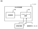
- the deterioration determination device 1-3 may be realized by a processing circuit 94 as shown in FIG. 8.
- the processing circuit 94 is connected to the constant voltage power supply 32 via an interface circuit 95 and receives the start-up command S1.
- the processing circuit 94 is dedicated hardware, the processing circuit 94 is, for example, a single circuit, a composite circuit, a programmed processor, a parallel programmed processor, an ASIC (Application Specific Integrated Circuit), an FPGA (Field Programmable Gate Array), or a combination of these.
- Each part of the deterioration determination device 1 may be realized by a separate processing circuit 94, or each part of the deterioration determination device 1 may be realized by a common processing circuit 94.
- the deterioration determination device 1 may be realized by dedicated hardware, and other parts may be realized by software or firmware.
- the signal processing unit 11 may be realized by the processing circuit 94 shown in FIG. 8, and the deterioration determination unit 12 may be realized by the processor 91 shown in FIG. 2 reading and executing a program stored in the memory 92.
Landscapes
- Engineering & Computer Science (AREA)
- Power Engineering (AREA)
- Electric Propulsion And Braking For Vehicles (AREA)
Abstract
Description
スイッチング素子を有する電子機器の一例として、鉄道車両に搭載される電力変換装置がある。電力変換装置に、スイッチング素子のスイッチング動作を行うための動作電圧を出力する定電圧電源の劣化の有無を判別する劣化判別装置を例にして、実施の形態1に係る劣化判別装置について以下に説明する。図1に示す実施の形態1に係る劣化判別装置1は、電力変換装置20に動作電圧を出力する定電圧電源32の劣化の有無を判別する。
劣化判別装置1が行う劣化判別は、劣化の有無の判別に限られず、劣化の兆候の有無の判別を含むものでもよい。図5に示す実施の形態2に係る劣化判別装置2は、実施の形態1に係る劣化判別装置1の構成に加えて、定電圧電源32の劣化の兆候の有無を判別する兆候判別部13を備える。劣化判別装置2のハードウェア構成は、劣化判別装置1と同様である。
劣化判別装置は、複数の定電圧電源の起動時間から、各定電圧電源の劣化の有無を判別してもよい。図6に示す劣化判別装置3は、複数の電力変換装置20,40,60に、スイッチング素子のスイッチング動作を行うための動作電圧をそれぞれ出力する複数の定電圧電源32,34,36の劣化の有無を判別する。
Claims (6)
- スイッチング素子を有する電子機器に、前記スイッチング素子のスイッチング動作を行うための動作電圧を出力する定電圧電源の劣化の有無を判別する劣化判別装置であって、
前記定電圧電源の出力電圧から、前記出力電圧の振幅に基づく電圧データを生成する信号処理部と、
前記電子機器に対する起動指令、および前記電圧データから、前記定電圧電源の起動時間を求め、前記起動時間から前記定電圧電源の劣化の有無を判別する劣化判別部と、
を備える劣化判別装置。 - 前記劣化判別部は、前記起動指令が前記電子機器の起動を指示してから、前記電圧データが示す振幅が前記電子機器による前記スイッチング素子のスイッチング動作を行うために必要となる動作定格電圧に応じて定められる閾値に到達するまで、を前記起動時間として求める、
請求項1に記載の劣化判別装置。 - 前記信号処理部は、前記電子機器に前記スイッチング素子のスイッチング動作を行うための交流電圧である前記動作電圧を出力する前記定電圧電源の出力電圧を示す波形データに対して低域通過フィルタに基づくフィルタリングを行うことで、前記波形データの包絡線を示すアナログ領域の包絡線データを生成し、前記包絡線データをアナログ/デジタル変換することで、デジタル領域の前記電圧データを生成する、
請求項1または2に記載の劣化判別装置。 - 前記信号処理部は、同一の車両に搭載される複数の前記電子機器の内、対応する前記電子機器に該電子機器が有する前記スイッチング素子のスイッチング動作を行うための動作電圧を出力する複数の前記定電圧電源の出力電圧から、前記定電圧電源ごとに前記出力電圧の振幅に基づく前記電圧データを生成し、
前記劣化判別部は、前記電子機器に対する起動指令、および該電子機器に前記動作電圧を出力する前記定電圧電源の前記電圧データから、前記定電圧電源ごとに前記起動時間を求め、前記起動時間のばらつきから前記定電圧電源の劣化の有無を判別する、
請求項1から3のいずれか1項に記載の劣化判別装置。 - 前記劣化判別部は、前記起動指令が前記電子機器の起動を指示するたびに、前記起動時間を求め、
前記劣化判別部で求められた前記起動時間の経時変化から、前記定電圧電源の劣化の兆候の有無を判別する兆候判別部をさらに備える、
請求項1から4のいずれか1項に記載の劣化判別装置。 - スイッチング素子を有する電子機器に、前記スイッチング素子のスイッチング動作を行うための動作電圧を出力する定電圧電源の出力電圧から、前記出力電圧の振幅を示す電圧データを生成し、
前記電子機器に対する起動指令、および前記電圧データから、前記定電圧電源の起動時間を求め、前記起動時間から前記定電圧電源の劣化の有無を判別する、
劣化判別方法。
Priority Applications (3)
| Application Number | Priority Date | Filing Date | Title |
|---|---|---|---|
| DE112023006464.4T DE112023006464T5 (de) | 2023-06-06 | 2023-06-06 | Verschlechterungsbestimmungsvorrichtung und verschlechterungsbestimmungsverfahren |
| JP2025525389A JP7805528B2 (ja) | 2023-06-06 | 2023-06-06 | 劣化判別装置および劣化判別方法 |
| PCT/JP2023/021051 WO2024252529A1 (ja) | 2023-06-06 | 2023-06-06 | 劣化判別装置および劣化判別方法 |
Applications Claiming Priority (1)
| Application Number | Priority Date | Filing Date | Title |
|---|---|---|---|
| PCT/JP2023/021051 WO2024252529A1 (ja) | 2023-06-06 | 2023-06-06 | 劣化判別装置および劣化判別方法 |
Publications (1)
| Publication Number | Publication Date |
|---|---|
| WO2024252529A1 true WO2024252529A1 (ja) | 2024-12-12 |
Family
ID=93795342
Family Applications (1)
| Application Number | Title | Priority Date | Filing Date |
|---|---|---|---|
| PCT/JP2023/021051 Ceased WO2024252529A1 (ja) | 2023-06-06 | 2023-06-06 | 劣化判別装置および劣化判別方法 |
Country Status (3)
| Country | Link |
|---|---|
| JP (1) | JP7805528B2 (ja) |
| DE (1) | DE112023006464T5 (ja) |
| WO (1) | WO2024252529A1 (ja) |
Citations (2)
| Publication number | Priority date | Publication date | Assignee | Title |
|---|---|---|---|---|
| JPH06209583A (ja) * | 1992-11-20 | 1994-07-26 | Toyo Electric Mfg Co Ltd | 電圧形インバータ |
| JP2009261190A (ja) * | 2008-04-21 | 2009-11-05 | Mitsubishi Electric Corp | 電源装置および電源回路の経年劣化検知方法 |
Family Cites Families (4)
| Publication number | Priority date | Publication date | Assignee | Title |
|---|---|---|---|---|
| JP4951642B2 (ja) * | 2009-03-19 | 2012-06-13 | 株式会社日立製作所 | 電力変換装置及びそれを用いたエレベータ装置 |
| JP2016201934A (ja) | 2015-04-13 | 2016-12-01 | 東日本旅客鉄道株式会社 | 電源装置の劣化検知装置および劣化検知方法 |
| JP6632936B2 (ja) * | 2016-06-07 | 2020-01-22 | 三菱電機株式会社 | エレベータの制御装置 |
| JP7347297B2 (ja) * | 2020-03-30 | 2023-09-20 | 三菱電機株式会社 | インバータおよびエレベーター |
-
2023
- 2023-06-06 WO PCT/JP2023/021051 patent/WO2024252529A1/ja not_active Ceased
- 2023-06-06 DE DE112023006464.4T patent/DE112023006464T5/de active Pending
- 2023-06-06 JP JP2025525389A patent/JP7805528B2/ja active Active
Patent Citations (2)
| Publication number | Priority date | Publication date | Assignee | Title |
|---|---|---|---|---|
| JPH06209583A (ja) * | 1992-11-20 | 1994-07-26 | Toyo Electric Mfg Co Ltd | 電圧形インバータ |
| JP2009261190A (ja) * | 2008-04-21 | 2009-11-05 | Mitsubishi Electric Corp | 電源装置および電源回路の経年劣化検知方法 |
Also Published As
| Publication number | Publication date |
|---|---|
| DE112023006464T5 (de) | 2026-03-19 |
| JP7805528B2 (ja) | 2026-01-23 |
| JPWO2024252529A1 (ja) | 2024-12-12 |
Similar Documents
| Publication | Publication Date | Title |
|---|---|---|
| JP5947109B2 (ja) | 無停電電源装置、無停電電源装置の制御方法 | |
| US7489118B2 (en) | Method and apparatus for high-efficiency DC stabilized power supply capable of effectively reducing noises and ripples | |
| CN113454472B (zh) | 内置自测试电路和相关方法 | |
| KR20180022404A (ko) | 배터리 관리 장치 및 시스템 | |
| JP7805528B2 (ja) | 劣化判別装置および劣化判別方法 | |
| KR102848444B1 (ko) | 제어 장치, 인버터, 인버터 및 전기 머신을 구비하는 어셈블리, 인버터를 작동시키는 방법 및 컴퓨터 프로그램 | |
| WO2002101480A1 (en) | Power supply circuit and test apparatus | |
| US11632035B2 (en) | Capacitor diagnosis device and capacitor diagnosis method | |
| CN100561821C (zh) | 自动识别交流电压输入之系统及方法 | |
| CN112271700A (zh) | 母线电容的硬件保护装置、保护方法和一种用电电路 | |
| CN104145409B (zh) | 具有数字电流控制电路的电力转换器 | |
| JP5524729B2 (ja) | 電圧検出回路及び電力供給装置 | |
| CN106877639A (zh) | 开关电源、音频设备和快速关断开关电源的方法 | |
| US12113458B2 (en) | Drive system with common DC bus | |
| US10602601B2 (en) | Creeping discharge element drive device and creeping discharge element drive method | |
| CN116365495A (zh) | 电源管理系统、方法、装置、电子设备以及介质 | |
| CN117918048A (zh) | 太阳能发电系统的控制装置及电力变换装置 | |
| JP7366319B2 (ja) | 制御装置、電力変換装置および制御方法 | |
| JPH07107771A (ja) | モータ駆動装置 | |
| JP7805532B2 (ja) | 異常判別装置、電源装置、異常判別システムおよび異常判別方法 | |
| US9965905B1 (en) | Engine-state detection device and engine-state detection method | |
| CN112776663A (zh) | 电动汽车供电方法、装置和电子设备 | |
| JP2020092535A (ja) | 電力変換装置 | |
| JP7253855B1 (ja) | コンピュータプログラム、電源装置及び電源装置の制御方法 | |
| JP7482614B2 (ja) | 過電流検出装置、及びモータ制御装置 |
Legal Events
| Date | Code | Title | Description |
|---|---|---|---|
| 121 | Ep: the epo has been informed by wipo that ep was designated in this application |
Ref document number: 23940634 Country of ref document: EP Kind code of ref document: A1 |
|
| WWE | Wipo information: entry into national phase |
Ref document number: 2025525389 Country of ref document: JP |
|
| WWE | Wipo information: entry into national phase |
Ref document number: 202517120891 Country of ref document: IN |
|
| WWP | Wipo information: published in national office |
Ref document number: 202517120891 Country of ref document: IN |
|
| WWE | Wipo information: entry into national phase |
Ref document number: 112023006464 Country of ref document: DE |
|
| WWP | Wipo information: published in national office |
Ref document number: 112023006464 Country of ref document: DE |