WO2024252463A1 - 電力変換装置、電動車両駆動装置、及び電力変換装置の製造方法 - Google Patents
電力変換装置、電動車両駆動装置、及び電力変換装置の製造方法 Download PDFInfo
- Publication number
- WO2024252463A1 WO2024252463A1 PCT/JP2023/020806 JP2023020806W WO2024252463A1 WO 2024252463 A1 WO2024252463 A1 WO 2024252463A1 JP 2023020806 W JP2023020806 W JP 2023020806W WO 2024252463 A1 WO2024252463 A1 WO 2024252463A1
- Authority
- WO
- WIPO (PCT)
- Prior art keywords
- cooling surface
- conversion device
- power conversion
- housing
- power
- Prior art date
- Legal status (The legal status is an assumption and is not a legal conclusion. Google has not performed a legal analysis and makes no representation as to the accuracy of the status listed.)
- Ceased
Links
Images










Classifications
-
- H—ELECTRICITY
- H02—GENERATION; CONVERSION OR DISTRIBUTION OF ELECTRIC POWER
- H02M—APPARATUS FOR CONVERSION BETWEEN AC AND AC, BETWEEN AC AND DC, OR BETWEEN DC AND DC, AND FOR USE WITH MAINS OR SIMILAR POWER SUPPLY SYSTEMS; CONVERSION OF DC OR AC INPUT POWER INTO SURGE OUTPUT POWER; CONTROL OR REGULATION THEREOF
- H02M1/00—Details of apparatus for conversion
- H02M1/32—Means for protecting converters other than automatic disconnection
- H02M1/327—Means for protecting converters other than automatic disconnection against abnormal temperatures
-
- H—ELECTRICITY
- H02—GENERATION; CONVERSION OR DISTRIBUTION OF ELECTRIC POWER
- H02M—APPARATUS FOR CONVERSION BETWEEN AC AND AC, BETWEEN AC AND DC, OR BETWEEN DC AND DC, AND FOR USE WITH MAINS OR SIMILAR POWER SUPPLY SYSTEMS; CONVERSION OF DC OR AC INPUT POWER INTO SURGE OUTPUT POWER; CONTROL OR REGULATION THEREOF
- H02M7/00—Conversion of AC power input into DC power output; Conversion of DC power input into AC power output
- H02M7/003—Constructional details, e.g. physical layout, assembly, wiring or busbar connections
-
- H—ELECTRICITY
- H05—ELECTRIC TECHNIQUES NOT OTHERWISE PROVIDED FOR
- H05K—PRINTED CIRCUITS; CASINGS OR CONSTRUCTIONAL DETAILS OF ELECTRIC APPARATUS; MANUFACTURE OF ASSEMBLAGES OF ELECTRICAL COMPONENTS
- H05K7/00—Constructional details common to different types of electric apparatus
- H05K7/20—Modifications to facilitate cooling, ventilating, or heating
- H05K7/2089—Modifications to facilitate cooling, ventilating, or heating for power electronics, e.g. for inverters for controlling motor
- H05K7/20927—Liquid coolant without phase change
-
- H—ELECTRICITY
- H02—GENERATION; CONVERSION OR DISTRIBUTION OF ELECTRIC POWER
- H02M—APPARATUS FOR CONVERSION BETWEEN AC AND AC, BETWEEN AC AND DC, OR BETWEEN DC AND DC, AND FOR USE WITH MAINS OR SIMILAR POWER SUPPLY SYSTEMS; CONVERSION OF DC OR AC INPUT POWER INTO SURGE OUTPUT POWER; CONTROL OR REGULATION THEREOF
- H02M7/00—Conversion of AC power input into DC power output; Conversion of DC power input into AC power output
- H02M7/42—Conversion of DC power input into AC power output without possibility of reversal
- H02M7/44—Conversion of DC power input into AC power output without possibility of reversal by static converters
- H02M7/48—Conversion of DC power input into AC power output without possibility of reversal by static converters using discharge tubes with control electrode or semiconductor devices with control electrode
- H02M7/53—Conversion of DC power input into AC power output without possibility of reversal by static converters using discharge tubes with control electrode or semiconductor devices with control electrode using devices of a triode or transistor type requiring continuous application of a control signal
- H02M7/537—Conversion of DC power input into AC power output without possibility of reversal by static converters using discharge tubes with control electrode or semiconductor devices with control electrode using devices of a triode or transistor type requiring continuous application of a control signal using semiconductor devices only, e.g. single switched pulse inverters
- H02M7/5387—Conversion of DC power input into AC power output without possibility of reversal by static converters using discharge tubes with control electrode or semiconductor devices with control electrode using devices of a triode or transistor type requiring continuous application of a control signal using semiconductor devices only, e.g. single switched pulse inverters in a bridge configuration
Definitions
- This application relates to a power conversion device, an electric vehicle drive device, and a method for manufacturing a power conversion device.
- Patent Document 1 the main parts of the power conversion device are composed of a power module incorporating semiconductor elements such as IGBTs, a drive circuit that drives the power module, a control circuit that controls them, a smoothing capacitor that smoothes the input voltage of the power module, and a cooler in which a refrigerant flow path is formed.
- Patent Document 1 only functions as a product once its main components are assembled into a housing, making it difficult to check the functionality and performance of the power conversion device before assembling it into the housing. This is not only disadvantageous in terms of improving the productivity of power conversion devices, but also poses problems in terms of ensuring quality.
- Patent Document 2 A configuration has been disclosed that allows the function and performance of a power conversion device to be confirmed before it is installed in a housing (see, for example, Patent Document 2).
- the power conversion device disclosed in Patent Document 2 is a high-voltage unit that can perform the minimum main functions required of a power conversion device, namely, cooling function and inverter function, before being installed in a housing, and is a complete unit in which both functions can be inspected.
- the power conversion device functions before being installed in the housing, so that the functions can be inspected before being installed in the housing.
- the power module is placed on one side of the water-cooled jacket, and the bus bar and smoothing capacitor are mounted on top of the power module. Therefore, heat-generating components other than the power module (e.g., smoothing capacitors) cannot be thermally connected to the water-cooled jacket while ensuring a sufficient heat dissipation area, which creates the problem of reduced cooling performance of the power conversion device.
- the present application therefore aims to obtain a power conversion device with excellent cooling performance and improved productivity.
- the power conversion device disclosed in the present application comprises one or more power modules having one or more semiconductor elements connected to a power supply connection terminal connected to a DC power supply, a control board for controlling the switching operation of the semiconductor elements, and an electrical component, a smoothing capacitor for smoothing the input voltage input from the DC power supply to the power module, at least one of a reactor, a step-up converter unit, a step-down converter unit, and a transmission control unit which are electrical components electrically connected to the power module, and an electrical interface between the power supply connection terminal and the power module, between the power supply connection terminal and at least one of the electrical components, and between the power module and at least one of the electrical components.
- the power module, the smoothing capacitor, the reactor, the step-up converter unit, the step-down converter unit, the transmission control unit, and the busbar assembly are heat-generating components, and the first and second cooling surfaces are provided parallel to each other on both sides of the refrigerant flow path, and at least one of the heat-generating components is thermally connected to the first cooling surface, and at least one of the heat-generating components is thermally connected to the second cooling surface.
- the power conversion device disclosed in the present application includes one or more power modules, a control board, at least one of electrical components selected from the group consisting of a smoothing capacitor, a reactor, a step-up converter unit, a step-down converter unit, and a transmission control unit, a busbar assembly having a busbar, and a cooler having a first cooling surface and a second cooling surface and having a refrigerant flow path formed inside.
- the power module, smoothing capacitor, reactor, step-up converter unit, step-down converter unit, transmission control unit, and busbar assembly are heat-generating components, and the first and second cooling surfaces are provided parallel to each other on both sides of the refrigerant flow path, and at least one heat-generating component is thermally connected to the first cooling surface and at least one heat-generating component is thermally connected to the second cooling surface.
- the power conversion device can perform the main functions required of a power conversion device (e.g., inverter function, cooling function) without being incorporated into a housing or the like, and is completed as an integrated unit that can be inspected, which improves the productivity of the power conversion device 1.
- a power conversion device e.g., inverter function, cooling function
- FIG. 1 is a side view showing an outline of a power conversion device according to a first embodiment
- 1 is a side view showing an outline of a power conversion device according to a first embodiment
- 1 is a diagram illustrating an example of a circuit configuration of a power converter according to a first embodiment
- 4 is a side view showing an outline of another power conversion device according to the first embodiment.
- FIG. 4 is a side view showing an outline of another power conversion device according to the first embodiment.
- FIG. 3A to 3C are diagrams illustrating a manufacturing process for the power conversion device according to the first embodiment.
- 11 is a side view showing an outline of a power conversion device according to a second embodiment.
- FIG. 11 is a side view showing an outline of a power conversion device according to a second embodiment.
- FIG. 11 is a side view showing an outline of another power conversion device according to the second embodiment.
- FIG. 11 is a side view showing an outline of another power conversion device according to the second embodiment.
- FIG. 11A to 11C are diagrams showing a manufacturing process of a power conversion device according to a second embodiment.
- FIG. 11 is a side view showing an outline of a power conversion device according to a third embodiment.
- FIG. 11 is a side view showing an outline of a power conversion device according to a third embodiment.
- FIG. 11 is a side view showing an outline of another power conversion device according to the third embodiment.
- FIG. 11 is a side view showing an outline of another power conversion device according to the third embodiment.
- FIG. 13 is a side view showing an outline of a power conversion device according to a fourth embodiment.
- FIG. 11 is a side view showing an outline of a power conversion device according to a fourth embodiment.
- FIG. 13 is a side view showing an outline of a power conversion device according to a fourth embodiment.
- FIG. 13 is a side view showing an outline of another power conversion device according to the fourth embodiment.
- FIG. 13 is a side view showing an outline of another power conversion device according to the fourth embodiment.
- FIG. 13 is a side view showing an outline of another power conversion device according to the fourth embodiment.
- FIG. 13 is a side view showing an outline of another power conversion device according to the fourth embodiment.
- FIG. 13 is a side view showing an outline of a power conversion device according to a fifth embodiment.
- FIG. 13 is a side view showing an outline of a power conversion device according to a fifth embodiment.
- FIG. 13 is a side view showing an outline of another power conversion device according to the fifth embodiment.
- FIG. 13 is a side view showing an outline of another power conversion device according to the fifth embodiment.
- FIG. 13 is a side view showing an outline of another power conversion device according to the fifth embodiment.
- FIG. 13 is a side view showing an outline of a power conversion device according to a sixth embodiment.
- FIG. 13 is a side view showing an outline of a power conversion device according to a sixth embodiment.
- FIG. 13 is a side view showing an outline of another power conversion device according to the sixth embodiment.
- FIG. 13 is a side view showing an outline of another power conversion device according to the sixth embodiment.
- FIG. 13 is a side view showing an outline of another power conversion device according to the sixth embodiment.
- FIG. 13 is a side view showing an outline of a power conversion device according to a seventh embodiment.
- FIG. 13 is a side view showing an outline of a power conversion device according to a seventh embodiment.
- FIG. 13 is a side view showing an outline of another power conversion device according to the seventh embodiment.
- FIG. 13 is a side view showing an outline of another power conversion device according to the seventh embodiment.
- FIG. 13 is a schematic diagram showing an outline of an electric vehicle drive device according to an eighth embodiment.
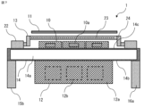
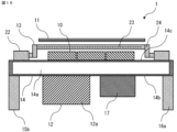
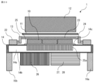
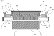
- FIG. 1 is a side view showing an outline of the power conversion device 1 according to the first embodiment, with a part of the side wall of the cooler 14 removed;
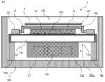
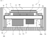
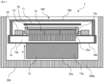
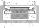
- FIG. 2 is a side view showing an outline of the power conversion device 1, with a part of the peripheral wall of the housing 200 removed;
- FIG. 3 is a diagram showing an example of a circuit configuration of the power conversion device 1;
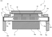
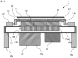
- FIG. 4 is a side view showing an outline of another power conversion device 1 according to the first embodiment, with a part of the side wall of the cooler 14 removed;
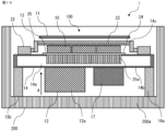
- FIG. 5 is a side view showing an outline of another power conversion device 1, with a part of the peripheral wall of the housing 200 removed; and
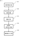
- FIG. 6 is a diagram showing a manufacturing process of the power conversion device 1.
- the power conversion device 1 is a device that converts an input current from DC to AC, AC to DC, or an input voltage into a different voltage.
- the power conversion device 1 is described as an inverter that converts DC power into AC power and supplies the AC power to a drive motor of a hybrid vehicle or an electric vehicle, but the power conversion device 1 disclosed in the present application is not limited to an inverter.
- the power conversion device 1 includes a power module 10 and a smoothing capacitor 12 that smoothes the input voltage input to the power module 10 from a DC power source 21.
- the power conversion device 1 is connected to an external DC power source 21.
- the power conversion device 1 includes a bus bar 13a through which DC power flows and a bus bar 13b through which AC power flows.
- the smoothing capacitor 12 is electrically connected to the bus bar 13a.
- the power module 10 is electrically connected to the bus bar 13a and the bus bar 13b.
- the power module 10 is connected to a power supply connection terminal 22 that is connected to the DC power source 21, and includes one or more semiconductor elements 10a.
- the power module 10 includes six semiconductor elements 10a, but the number of the semiconductor elements 10a is not limited thereto.
- the semiconductor elements 10a convert DC power and AC power.
- the AC power is output from the bus bar 13b to the drive motor 300, and drives a rotating electric machine including the drive motor 300.
- the power conversion device 1 may be configured to convert the AC power output from the generator into DC power in order to charge the DC power supply 21.
- the semiconductor element 10a may be a power control semiconductor element such as a MOSFET (Metal Oxide Semiconductor Field Effect Transistor) or an IGBT (Insulated Gate Bipolar Transistor), or a freewheeling diode.
- the semiconductor element 10a is not limited to these, and may be other semiconductor elements such as a bipolar transistor. It may also be an RC-IGBT (Reverse Conducting IGBT) in which a switching element and a freewheeling diode are integrated.
- the semiconductor element 10a is formed on a semiconductor substrate made of a material such as silicon, silicon carbide, or gallium nitride, and a wide bandgap semiconductor element with a wider bandgap than silicon can be used for the semiconductor element 10a.
- a MOSFET made of silicon carbide which is a wide bandgap semiconductor element
- the time change in current di/dt that occurs during switching can be made larger than that of a MOSFET made of silicon.
- wide bandgap semiconductor elements have low on-resistance, low loss, and low heat generation, making it possible to reduce the chip area. Because the chip area is reduced, the power module 10 can be made smaller.
- the configuration of the power conversion device 1 will be described with reference to Fig. 1.
- the power conversion device 1 includes one or more power modules 10, a control board 11, at least one electric component, a bus bar assembly 13, and a cooler 14.
- the power module 10 is connected to a power supply connection terminal 22 connected to a DC power supply 21, and includes one or more semiconductor elements 10a.
- the power conversion device 1 includes three power modules 10, but the number of power modules 10 is not limited to this.
- the number of semiconductor elements 10a included in each of the power modules 10 is, for example, two.
- the control board 11 controls the switching operation of the semiconductor elements 10a.
- the power conversion device 1 includes, as an electrical component, a smoothing capacitor 12 that smoothes the input voltage input from the DC power source 21 to the power module 10.
- the electrical component is not limited to the smoothing capacitor 12.
- Other electrical components include, for example, a reactor, a step-up converter unit, a step-down converter unit, and a transmission control unit that are electrically connected to the power module 10. The other electrical components will be described later.
- the busbar assembly 13 has a busbar 13a that electrically connects at least one of the following: between the power supply connection terminal 22 and the power module 10, between the power supply connection terminal 22 and at least one electrical component, and between the power module 10 and at least one electrical component.
- the busbar assembly 13 has a busbar 13a that electrically connects between the power supply connection terminal 22 and the power module 10, between the power supply connection terminal 22 and the smoothing capacitor 12, and between the power module 10 and the smoothing capacitor 12.
- the busbar assembly 13 has both busbars 13a and 13b shown in FIG. 3. Note that in FIG. 1 and FIG. 2, the busbars 13a and 13b are collectively shown by dashed lines as the busbar 23, and the busbars 13a and 13b are not shown in FIG. 1 and FIG. 2.
- the cooler 14 has a first cooling surface 14b and a second cooling surface 14c opposite the first cooling surface 14b, and a refrigerant flow path 14a is formed inside.
- the power module 10, the smoothing capacitor 12, the reactor, the step-up converter unit, the step-down converter unit, the transmission control unit, and the busbar assembly 13 are heat-generating components.
- the first cooling surface 14b and the second cooling surface 14c are provided parallel to each other on both sides of the refrigerant flow path 14a. At least one heat-generating component is thermally connected to the first cooling surface 14b, and at least one heat-generating component is thermally connected to the second cooling surface 14c.
- the smoothing capacitor 12, which is a heat-generating component is thermally connected to the first cooling surface 14b
- the power module 10, which is a heat-generating component is thermally connected to the second cooling surface 14c.
- both of the two heat-generating components are thermally connected to the cooler 14 without increasing the size of the cooler 14. Because both of the two heat-generating components are thermally connected to the cooler 14, the heat dissipation properties of the two heat-generating components are improved, making it possible to obtain a power conversion device 1 with excellent cooling performance. In addition, because the heat dissipation properties of the two heat-generating components are improved, both of the two heat-generating components can be made smaller. Because both of the two heat-generating components are made smaller, the power conversion device 1 can be made smaller.
- the power conversion device 1 is housed in a case or the like and is mounted on a hybrid vehicle or an electric vehicle.
- the power conversion device 1 has a power conversion function and a cooling function, and the power conversion function and the cooling function can be inspected.
- the power conversion device 1 shown in FIG. 1 can perform the main functions required of the power conversion device 1 (e.g., inverter function, cooling function) without being incorporated into a case or the like, and is completed as an integrated unit that can be inspected, so the productivity of the power conversion device 1 can be improved.
- the power conversion device 1 is assembled to a drive motor or e-Axle, it is possible to suppress the size of the inspection equipment for the power conversion device 1.
- the inspection accuracy of the power conversion device 1 can be improved. Since the inspection accuracy of the power conversion device 1 is improved, the quality of the power conversion device 1 can be ensured.
- the power conversion device 1 shown in FIG. 1 is referred to as a subassembly 100 in FIG. 2.
- the power conversion device 1 includes a housing 200.
- the heat generating components, the control board 11, and the cooler 14 are accommodated in the housing 200.
- the heat generating components are the power module 10, the smoothing capacitor 12, and the busbar assembly 13.
- the first cooling surface 14b and the second cooling surface 14c are perpendicular to the normal direction of the facing surface of the housing 200 that faces the first cooling surface 14b or the second cooling surface 14c.
- the housing 200 is formed in a bottomed cylindrical shape, and the facing surface of the housing 200 is the inner surface of the bottom wall 200a of the housing 200.
- the housing 200 is not limited to a bottomed cylindrical shape, but when the housing 200 is a bottomed cylindrical shape, the housing 200 can be easily manufactured.
- the normal direction of the inner surface of bottom wall 200a is the direction indicated by arrow A in Fig. 2.
- smoothing capacitor 12 is disposed on the side facing the assembly direction of subassembly 100 to housing 200 (opposite the normal direction).
- the assembly direction of the subassembly 100 to the housing 200 is perpendicular to the first cooling surface 14b and the second cooling surface 14c, so the subassembly 100 can be easily assembled to the housing 200. Since the subassembly 100 can be easily assembled to the housing 200, the productivity of the power conversion device 1 can be improved.
- the housing 200 is formed of, for example, aluminum or an aluminum alloy. By manufacturing the housing 200 by die casting using aluminum or an aluminum alloy, the housing 200 can be easily manufactured. In addition, the weight of the housing 200 can be reduced.
- the housing 200 may be integrated with an external device, and the external device may be, for example, a drive motor or an e-Axle.
- the cooler 14 is made of, for example, aluminum or an aluminum alloy. By manufacturing the cooler 14 by die casting using aluminum or an aluminum alloy, the cooler 14 can be easily manufactured. In addition, the weight of the cooler 14 can be reduced.
- a refrigerant (not shown) flows through the refrigerant flow path 14a.
- the refrigerant is, for example, LLC (long life coolant).
- the cooler 14 in this embodiment is a water-cooled type cooler.
- the refrigerant flow path 14a is formed, for example, parallel to the first cooling surface 14b and the second cooling surface 14c. By flowing the refrigerant parallel to the first cooling surface 14b and the second cooling surface 14c, the first cooling surface 14b and the second cooling surface 14c can be cooled efficiently.
- the cooler 14 has a refrigerant inlet and outlet (not shown). The refrigerant flows into or out of the cooler 14 from the outside of the housing 200 through the refrigerant inlet and outlet.
- the subassembly 100 is fixed to the housing 200, for example, using a connection boss (not shown) provided on the cooler 14.
- the semiconductor element 10a of the power module 10 is, for example, an IGBT.
- the power module 10 has a plurality of high-voltage main circuit terminals and a plurality of signal terminals, not shown.
- the high-voltage main circuit terminals are connected to a bus bar 23 of the bus bar assembly 13.
- the plurality of signal terminals are connected to a control board 11.
- the power module 10 generates heat due to the high-speed switching operation of the semiconductor element 10a.
- the heat generated in the power module 10 is transferred via the cooler 14 to the refrigerant flowing through the refrigerant flow path 14a.
- the power module 10 is thermally connected directly to the cooler 14, but this is not limited to the present embodiment.
- the power module 10 may also be thermally connected to the cooler 14 via a heat sink.
- the heat sink is a material with excellent thermal conductivity, such as grease, solder, gap filler, or compound.
- the busbar assembly 13 has a plurality of busbars 23 and a retaining member 24.
- the busbars 23 are made of, for example, copper, which has excellent electrical conductivity.
- the retaining member 24 is made of an insulating resin.
- the busbars 23 and the retaining member 24 are integrated together by insert molding. By being integrally molded, the busbars 23 are held by the retaining member 24. Furthermore, each of the plurality of busbars 23 is insulated from the other by the retaining member 24.
- the bus bar 23 is electrically connected to a high-voltage main circuit terminal extending from the power module 10.
- the bus bar 23 is connected to the high-voltage main circuit terminal by, for example, fastening with screws or TIG welding.
- the bus bar 13a which is the DC line of the bus bar 23, is electrically connected to the smoothing capacitor 12, and the bus bar 13b, which is the AC line of the bus bar 23, is electrically connected to the drive motor 300 (not shown in FIG. 1).
- the busbar assembly 13 is disposed on the opposite side of the power module 10 from the cooler 14 side.
- the busbar assembly 13 has both busbars 13a and 13b, but this is not limited to this.
- a busbar assembly having busbar 13a and a busbar assembly having busbar 13b may be provided separately.
- the busbar assembly 13 is formed by insert molding, but this is not limited to this.
- the busbar assembly 13 may be formed by the busbar 23 and an insulating member provided around the busbar 23 without insert molding.
- the insulating member is, for example, insulating paper or resin.
- the busbar 13a may be formed as a parallel plate directly above the power module 10.
- the control board 11 has a drive circuit and a control circuit.
- the drive circuit drives the power module 10.
- the control circuit controls the drive circuit.
- the control board 11 is arranged on the side of the bus bar assembly 13 opposite the power module 10. By arranging the control board 11 in this manner, the influence of heat from the power module 10 to the control board 11 can be suppressed, but the arrangement of the control board 11 is not limited to this.
- the control board 11 may be arranged, for example, between the bus bar assembly 13 and the power module 10, or at the same height as the bus bar assembly 13.
- control board 11 is configured as a single board, but this is not limited to this. Taking into consideration functionality, layout, productivity, etc., the control board 11 may be configured by dividing it into multiple boards. For example, the control board 11 may be divided into a drive circuit and a control circuit. Also, in this embodiment, the control board 11 is fixed to a board fixing boss (not shown) provided on the bus bar assembly 13. The location to which the control board 11 is fixed is not limited to the bus bar assembly 13, and may be, for example, the cooler 14 or the smoothing capacitor 12.
- the smoothing capacitor 12 smoothes the input voltage of the power module 10.
- the smoothing capacitor 12 has a case 12a, a plurality of capacitor elements 12b, and a plurality of capacitor bus bars (not shown).
- the plurality of capacitor elements 12b are housed in the case 12a.
- the case 12a is formed, for example, from a synthetic resin.
- the smoothing capacitor 12 which is a heat generating component, is thermally connected to the first cooling surface 14b or the second cooling surface 14c.
- the smoothing capacitor 12 is thermally connected to the first cooling surface 14b.
- This configuration allows the smoothing capacitor 12, which generates a large amount of heat, to be thermally connected to the cooler 14. Since the smoothing capacitor 12 is thermally connected to the cooler 14, the heat dissipation of the smoothing capacitor 12 is improved, and a power conversion device 1 with excellent cooling performance can be obtained. Furthermore, since the heat dissipation of the smoothing capacitor 12 is improved, the capacitor element 12b of the smoothing capacitor 12 can be made smaller. Since the capacitor element 12b is made smaller, the smoothing capacitor 12 is made smaller, and the power conversion device 1 can be made smaller.
- a wound film capacitor is used for the capacitor element 12b.
- the wound film capacitor is flattened into an oval shape.
- the capacitor element 12b is sealed inside the case 12a by filling the inside of the case 12a with epoxy resin.
- One end of the capacitor bus bar is connected to the capacitor element 12b.
- the other end of the capacitor bus bar protrudes outside the case 12a and is connected to the bus bar 13a inside the bus bar assembly 13.
- the other end of the capacitor bus bar is connected to the bus bar 13a by, for example, fastening with screws or TIG welding.
- the other end of the capacitor bus bar may be electrically connected to the high-voltage main circuit terminal of the power module 10 by, for example, fastening with screws or TIG welding.
- the smoothing capacitor 12 generates heat through Joule heating caused by its own equivalent series resistance (ESR) and by receiving heat from the power module 10.
- ESR equivalent series resistance
- the heat generated in the smoothing capacitor 12 is transferred via the cooler 14 to the refrigerant flowing through the refrigerant flow path 14a.
- the smoothing capacitor 12 is thermally connected directly to the cooler 14, but this is not limited to the present invention.
- the smoothing capacitor 12 may also be thermally connected to the cooler 14 via a heat sink.
- the heat sink is a material with excellent thermal conductivity, such as grease, solder, gap filler, or compound.
- the heat generating component thermally connected to the first cooling surface 14b has a flat surface formed parallel to the first cooling surface 14b on the side opposite to the first cooling surface 14b.
- the heat generating component thermally connected to the first cooling surface 14b is the smoothing capacitor 12
- the smoothing capacitor 12 has a flat surface 15a formed parallel to the first cooling surface 14b.
- the flat surface 15a is formed parallel to the refrigerant flow path 14a.
- other heat generating components except for the smoothing capacitor 12, which is a heat generating component thermally connected to the first cooling surface 14b, and the control board 11 are not provided.
- the flat surface 15a becomes the surface on the side in the assembly direction of the subassembly 100.
- the heat-generating component thermally connected to the first cooling surface 14b is a heat-generating component other than the smoothing capacitor 12
- a flat portion may be provided on the heat-generating component other than the smoothing capacitor 12 thermally connected to the first cooling surface 14b, for example, the busbar assembly 13.
- the power conversion device 1 shown in FIG. 1 can be made to stand on its own by the flat surface 15a, which is the base surface. Because the power conversion device 1 can stand on its own, the stability of the power conversion device 1 is improved when it is transported, for example, by conveyor, and assembly work into the housing 200 can be easily performed. Because assembly work into the housing 200 can be easily performed, the productivity of the power conversion device 1 can be improved. In addition, because assembly work into the housing 200 is easy, the quality of the power conversion device 1 during assembly can be advantageously ensured.
- the productivity of the power conversion device 1 can be improved.
- heat-generating components are placed on both sides of the cooler 14, it may be difficult to stabilize the product posture during transportation in the state of the power conversion device 1 shown in FIG. 1 due to differences in the dimensions and shapes of each component. Therefore, providing a flat surface 15a on the surface on the side in the assembly direction to the housing 200, as disclosed herein, directly leads to improved productivity of the power conversion device 1.
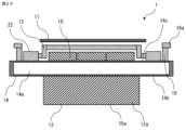
- Fig. 4 shows a modification of the power converter 1 shown in Fig. 1
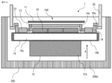
- Fig. 5 shows a modification of the power converter 1 shown in Fig. 2.
- the cooler 14 communicates with the refrigerant flow path 14a and has an opening provided on the first cooling surface or the second cooling surface, and a heat dissipation plate 25 covering the opening.
- an opening 14d is provided on the second cooling surface 14c.
- the heat dissipation plate 25 has a plurality of heat dissipation fins 25a protruding toward the refrigerant flow path 14a on the surface on the side of the refrigerant flow path 14a.
- the heat dissipation plate 25 is made of, for example, aluminum having excellent thermal conductivity.
- a first or second cooling surface is formed on the surface of the heat dissipation plate 25 opposite the side of the refrigerant flow path 14a.
- the power module 10 is thermally connected to the first or second cooling surface of the heat dissipation plate 25.
- a second cooling surface 14c is formed on the surface of the heat dissipation plate 25 opposite the side of the refrigerant flow path 14a, and the power module 10 is thermally connected to the second cooling surface 14c of the heat dissipation plate 25.
- the method of sealing between the heat dissipation plate 25 and the cooler 14 is, for example, a packing, FSW (Friction Stir Welding), or electron beam welding.
- the heat dissipation area in the refrigerant flow path 14a can be increased. Because the heat dissipation area is increased, the heat dissipation performance of the power module 10 can be improved. Because the heat dissipation performance of the power module 10 is improved, a power conversion device 1 with excellent cooling performance can be obtained. In addition, because the heat dissipation performance of the power module 10 is improved, the power conversion device 1 can be made smaller.
- the manufacturing method of the power conversion device 1 will be described with reference to FIG. 6.
- the manufacturing method of the power conversion device 1 includes a member preparation step (S11), a subassembly formation step (S12), and a housing assembly step (S13).
- the manufacturing method including an inspection step (S12-1) will be described last. Each step will be described below.
- the component preparation process is a process of preparing one or more power modules 10, each having one or more semiconductor elements 10a and connected to a power connection terminal 22 connected to a DC power source, a control board 11 that controls the switching operation of the semiconductor elements 10a, a smoothing capacitor 12 that smoothes the input voltage input from the DC power source to the power module 10, a bus bar assembly 13 having a bus bar 13a that electrically connects at least two of the power connection terminal 22, the power module 10, and the smoothing capacitor 12, a cooler 14 having a first cooling surface 14b and a second cooling surface 14c opposite the first cooling surface 14b, and with a refrigerant flow path 14a formed on the inside, and a housing 200 formed in a cylindrical shape with a bottom.
- the subassembly forming process is a process of thermally connecting at least one of the power module 10, the smoothing capacitor 12, and the busbar assembly 13 to the first cooling surface 14b, and thermally connecting at least one of the power module 10, the smoothing capacitor 12, and the busbar assembly 13 to the second cooling surface 14c, and forming a subassembly of the power conversion device 1 from the power module 10, the control board 11, the smoothing capacitor 12, the busbar assembly 13, and the cooler 14.
- the subassembly of the power conversion device 1 formed in this process has the configuration of the power conversion device 1 shown in FIG. 1, for example.
- the smoothing capacitor 12 is thermally connected to the first cooling surface 14b
- the power module 10 is thermally connected to the second cooling surface 14c.
- the busbar assembly 13 is arranged on the side opposite the cooler 14 side of the power module 10.
- the control board 11 is arranged on the side opposite the power module 10 side of the busbar assembly 13.
- the housing assembly process is a process of housing the subassembly in the housing 200.
- the power conversion device 1 formed in this process has the configuration of the power conversion device 1 shown in FIG. 2, for example.
- the subassembly 100 is fixed to the housing 200, for example, using a connection boss (not shown) provided on the cooler 14.
- the first cooling surface 14b and the second cooling surface 14c are provided parallel to each other on both sides of the refrigerant flow path 14a, and the first cooling surface 14b and the second cooling surface 14c are perpendicular to the normal direction of the inner surface of the bottom wall 200a of the housing 200.
- the assembly direction of the subassembly 100 to the housing 200 is the perpendicular direction of the first cooling surface 14b and the second cooling surface 14c.
- the assembly direction of the subassembly 100 to the housing 200 is perpendicular to the first cooling surface 14b and the second cooling surface 14c, so the subassembly 100 can be easily assembled to the housing 200. Since the subassembly 100 can be easily assembled to the housing 200, the productivity of the power conversion device 1 can be improved.
- the subassembly 100 has a power conversion function and a cooling function
- the manufacturing method of the power conversion device 1 may include an inspection process for inspecting the power conversion function and the cooling function before the housing assembly process. By inspecting the power conversion function and the cooling function before the housing assembly process, the productivity of the power conversion device 1 can be improved.
- the power conversion device 1 comprises one or more power modules 10, a control board 11, a smoothing capacitor 12 which is an electrical component, a busbar assembly 13 having a busbar 23, and a cooler 14 which has a first cooling surface 14b and a second cooling surface 14c and has a refrigerant flow path 14a formed on the inside, and the power module 10, the smoothing capacitor 12, and the busbar assembly 13 are heat-generating components, and the first cooling surface 14b and the second cooling surface 14c are provided parallel to each other on both sides of the refrigerant flow path 14a, and the power module 10 which is one of the heat-generating components is thermally connected to the first cooling surface 14b, and the smoothing capacitor 12 which is also one of the heat-generating components is thermally connected to the second cooling surface 14c.
- the smoothing capacitor 12 which is another heat-generating component can be thermally connected to the cooler 14 without increasing the size of the cooler 14. Since both of the two heat generating components are thermally connected to the cooler 14, the heat dissipation of the two heat generating components is improved, and a power conversion device 1 with excellent cooling performance can be obtained.
- the power conversion device 1 shown in FIG. 1 has a power conversion function and a cooling function, and the power conversion function and the cooling function can be inspected.
- the power conversion device 1 can perform the main functions required of the power conversion device 1 (e.g., inverter function, cooling function) without being incorporated into a housing or the like, and is completed as an integrated unit that can be inspected, so the productivity of the power conversion device 1 can be improved.
- the main functions required of the power conversion device 1 e.g., inverter function, cooling function
- the power conversion device 1 includes a housing 200, and the heat generating components, control board 11, and cooler 14, which are the subassembly 100, are housed in the housing 200, and the first cooling surface 14b and the second cooling surface 14c face the first cooling surface 14b or the second cooling surface 14c.
- the subassembly 100 can be easily assembled to the housing 200 because the direction in which the subassembly 100 is assembled to the housing 200 is perpendicular to the first cooling surface 14b and the second cooling surface 14c. Since the subassembly 100 can be easily assembled to the housing 200, the productivity of the power conversion device 1 can be improved.
- the housing 200 is formed into a bottomed cylindrical shape, the housing 200 can be easily manufactured.
- the smoothing capacitor 12 which is a heat-generating component thermally connected to the first cooling surface 14b
- the smoothing capacitor 12 has a flat portion 15a formed parallel to the first cooling surface 14b on the side opposite the first cooling surface 14b, and no other heat-generating components other than the smoothing capacitor 12, which is a heat-generating component thermally connected to the first cooling surface 14b, and no control board 11 are provided on the side opposite the first cooling surface 14b of the flat portion 15a
- the power conversion device 1 shown in FIG. 1 can be made to stand on its own by the flat portion 15a, which is the base surface. Since the power conversion device 1 stands on its own, the stability of the power conversion device 1 is improved when it is transported, for example, by a conveyor, and the assembly work to the housing 200 can be easily performed. Since the assembly work to the housing 200 can be easily performed, the productivity of the power conversion device 1 can be improved. Furthermore, since the assembly work to the housing 200 is easy, the quality of the power conversion device 1 during assembly can be advantageously ensured.
- the smoothing capacitor 12 which is a heat-generating component
- the smoothing capacitor 12 that generates a large amount of heat can be thermally connected to the cooler 14. Because the smoothing capacitor 12 is thermally connected to the cooler 14, the heat dissipation properties of the smoothing capacitor 12 are improved, and a power conversion device 1 with excellent cooling performance can be obtained.
- the capacitor element 12b of the smoothing capacitor 12 can be made smaller. Because the capacitor element 12b is made smaller, the smoothing capacitor 12 is made smaller, and the power conversion device 1 can be made smaller.
- the heat dissipation plate 25 When the cooler 14 is connected to the refrigerant flow path 14a and has an opening on the first cooling surface or the second cooling surface and a heat dissipation plate 25 covering the opening, the heat dissipation plate 25 has a plurality of heat dissipation fins 25a protruding toward the refrigerant flow path 14a on the surface on the side of the refrigerant flow path 14a, the first cooling surface or the second cooling surface is formed on the surface of the heat dissipation plate 25 opposite the refrigerant flow path 14a, and the power module 10 is thermally connected to the first cooling surface or the second cooling surface of the heat dissipation plate 25, the heat dissipation area in the refrigerant flow path 14a can be enlarged, thereby improving the heat dissipation of the power module 10. Since the heat dissipation of the power module 10 is improved, a power conversion device 1 with excellent cooling performance can be obtained.
- the manufacturing method of the power conversion device 1 includes a component preparation process for preparing the power module 10, the control board 11, the smoothing capacitor 12, the busbar assembly 13, the cooler 14, and the housing 200, a component preparation process for thermally connecting at least one of the power module 10, the smoothing capacitor 12, and the busbar assembly 13 to the first cooling surface 14b, and a component preparation process for thermally connecting at least one of the power module 10, the smoothing capacitor 12, and the busbar assembly 13 to the second cooling surface 14c, and a component preparation process for thermally connecting the power module 10, the control board 11, the smoothing capacitor 12, and the busbar assembly 13 to the second cooling surface 14c.
- the first cooling surface 14b and the second cooling surface 14c are provided parallel to each other on both sides of the refrigerant flow path 14a, the first cooling surface 14b and the second cooling surface 14c are perpendicular to the normal direction of the inner surface of the bottom wall 200a of the housing 200, and the assembly direction of the subassembly to the housing 200 is perpendicular to the first cooling surface 14b and the second cooling surface 14c, so that the subassembly can be easily assembled to the housing 200.
- the productivity of the power conversion device 1 can be improved.
- the subassembly 100 has a power conversion function and a cooling function, and an inspection process for inspecting the power conversion function and the cooling function is provided before the housing assembly process, the power conversion function and the cooling function can be inspected before the housing assembly process, so that the productivity of the power conversion device 1 can be improved.
- Embodiment 2 A power converter 1 according to a second embodiment will be described.
- Fig. 7 is a side view showing the outline of the power converter 1 according to the second embodiment, with a part of the side wall of the cooler 14 removed
- Fig. 8 is a side view showing the outline of the power converter 1, with a part of the peripheral wall of the housing 200 removed
- Fig. 9 is a side view showing the outline of another power converter 1 according to the second embodiment, with a part of the side wall of the cooler 14 removed
- Fig. 10 is a side view showing the outline of another power converter 1, with a part of the peripheral wall of the housing 200 removed
- Fig. 11 is a diagram showing a manufacturing process of the power converter 1.
- the power converter 1 according to the second embodiment is configured to include a plurality of support columns 16a in addition to the configuration of the first embodiment.
- the power conversion device 1 is provided with a plurality of support pillars 16a on the side of the first cooling surface 14b, which protrude in a direction away from the first cooling surface 14b.
- the plurality of support pillars 16a are arranged inside the outer periphery of the first cooling surface 14b and are fixed to the first cooling surface 14b.
- the four support pillars 16a are arranged at the four corners of the first cooling surface 14b.
- the arrangement, fixing points, and number of the plurality of support pillars 16a are not limited to this.
- the support pillars 16a are made of, for example, iron, aluminum alloy, or resin material.
- the support pillars 16a are fixed, for example, by fastening with screws, fitting, adhesion, or welding.
- the support pillars 16a and the cooler 14 may be integrated.
- Each of the multiple support columns 16a has a support column flat portion 15b formed parallel to the first cooling surface 14b at the end opposite the first cooling surface 14b.
- Each of the support column flat portions 15b is provided on the same plane parallel to the first cooling surface 14b, and no heat-generating components or control board 11 are provided on the side of each support column flat portion 15b opposite the first cooling surface 14b.
- the power conversion device 1 shown in FIG. 7 can be made to stand on its own by the support column flat portion 15b, which is the base surface. Since the power conversion device 1 can stand on its own, the stability of the power conversion device 1 is improved when it is transported, for example, by conveyor, and therefore assembly work into the housing 200 can be easily performed. Since assembly work into the housing 200 can be easily performed, the productivity of the power conversion device 1 can be improved. Furthermore, since assembly work into the housing 200 is facilitated, the quality of the power conversion device 1 during assembly can be advantageously ensured. Furthermore, since the configuration does not form flat portions on the electrical components, the electrical components do not have any parts that are used for transportation, and damage to the electrical components during transportation can be suppressed.
- the configuration in which the power conversion device 1 shown in FIG. 7 is housed in a housing 200 will be described with reference to FIG. 8.
- the power conversion device 1 shown in FIG. 7 is referred to as a subassembly 100 in FIG. 8.
- the power conversion device 1 includes a housing 200.
- the heat-generating components, the control board 11, the cooler 14, and the support column 16a are housed in the housing 200.
- the heat-generating components are the power module 10, the smoothing capacitor 12, and the busbar assembly 13.
- the first cooling surface 14b and the second cooling surface 14c are perpendicular to the normal direction of the opposing surface of the housing 200 that faces the first cooling surface 14b or the second cooling surface 14c.
- the housing 200 is formed in a bottomed cylindrical shape, and the opposing surface of the housing 200 is the inner surface of the bottom wall 200a of the housing 200.
- the housing 200 is not limited to a bottomed cylindrical shape, but if the housing 200 is a bottomed cylindrical shape, the housing 200 can be easily manufactured.
- the normal direction of the inner surface of the bottom wall 200a is the direction indicated by the arrow A in FIG. 8.
- the support pillar flat portion 15b abuts against the inner surface of the bottom wall 200a of the housing 200.
- the subassembly 100 is fixed to the housing 200 by the support pillar flat portion 15b.
- the assembly direction of the subassembly 100 to the housing 200 is perpendicular to the first cooling surface 14b and the second cooling surface 14c, so the subassembly 100 can be easily assembled to the housing 200. Since the subassembly 100 can be easily assembled to the housing 200, the productivity of the power conversion device 1 can be improved. In addition, since the subassembly 100 can be fixed to the housing 200 by the support pillar flat portion 15b, the subassembly 100 can be easily fixed to the housing 200 without providing any other fixing members.
- the multiple support columns 16a are provided so as to be removable. With this configuration, the support columns 16a can be removed from the subassembly 100 when the subassembly 100 is assembled to the housing 200. By removing the support columns 16a, the weight of the power conversion device 1 can be reduced without compromising the stability of the subassembly 100 when it is transported by a conveyor.
- the manufacturing method of the detachable support pillar 16a will be described.
- the support pillar 16a is formed so as to be detachable with a screw, a screw hole is drilled in the main body of the support pillar 16a obtained by extrusion processing or die casting.
- the support pillar 16a is fastened to, for example, the cooler 14 or the busbar assembly 13 using the screw hole provided in the main body of the support pillar 16a.
- a detachable support pillar 16a is manufactured by insert molding a nut into the support pillar 16a made of resin.
- each support column flat portion 15b which is the base surface, will vary depending on the product shape or transportation form. Therefore, each support column flat portion 15b is provided on the same plane parallel to the first cooling surface 14b, and there are no heat-generating components or control board 11 provided on the side of each support column flat portion 15b opposite the first cooling surface 14b, and other than that, no particular dimensional constraints are placed on the support column 16a.
- Fig. 9 is a modification of the power converter 1 shown in Fig. 7
- Fig. 10 is a modification of the power converter 1 shown in Fig. 8.
- the cooler 14 communicates with the refrigerant flow path 14a and has an opening provided on the first cooling surface or the second cooling surface, and a heat dissipation plate 25 covering the opening.
- an opening 14d is provided on the second cooling surface 14c.
- the heat dissipation plate 25 has a plurality of heat dissipation fins 25a protruding toward the refrigerant flow path 14a on the surface on the side of the refrigerant flow path 14a.
- the heat dissipation plate 25 is formed of, for example, aluminum having excellent thermal conductivity.
- a first or second cooling surface is formed on the surface of the heat dissipation plate 25 opposite the refrigerant flow path 14a.
- the power module 10 is thermally connected to the first or second cooling surface of the heat dissipation plate 25.
- a second cooling surface 14c is formed on the surface of the heat dissipation plate 25 opposite the refrigerant flow path 14a, and the power module 10 is thermally connected to the second cooling surface 14c of the heat dissipation plate 25.
- the heat dissipation area in the refrigerant flow path 14a can be increased. Because the heat dissipation area is increased, the heat dissipation performance of the power module 10 can be improved. Because the heat dissipation performance of the power module 10 is improved, a power conversion device 1 with excellent cooling performance can be obtained. In addition, because the heat dissipation performance of the power module 10 is improved, the power conversion device 1 can be made smaller.
- the manufacturing method of the power conversion device 1 will be described with reference to Fig. 11.
- the manufacturing method of the power conversion device 1 includes a member preparation step (S11), a subassembly formation step (S12), a transport step (S13), a support pole removal step (S14), and a housing assembly step (S15). Each step will be described below.
- the component preparation process is a process of preparing one or more power modules 10 having one or more semiconductor elements 10a connected to a power supply connection terminal 22 connected to a DC power supply, a control board 11 that controls the switching operation of the semiconductor elements 10a, a smoothing capacitor 12 that smoothes the input voltage input from the DC power supply to the power module 10, a bus bar assembly 13 having a bus bar 13a that electrically connects at least two of the power supply connection terminal 22, the power module 10, and the smoothing capacitor 12, a cooler 14 having a first cooling surface 14b and a second cooling surface 14c opposite the first cooling surface 14b and having a refrigerant flow path 14a formed on the inside, multiple support columns 16a formed to be detachable, and a housing 200 formed in a cylindrical shape with a bottom.
- the subassembly formation process is a process of thermally connecting at least one of the power module 10, the smoothing capacitor 12, and the busbar assembly 13 to the first cooling surface 14b, thermally connecting at least one of the power module 10, the smoothing capacitor 12, and the busbar assembly 13 to the second cooling surface 14c, attaching a plurality of support columns 16a to the first cooling surface 14b so as to protrude in a direction away from the first cooling surface 14b, and forming a subassembly of the power conversion device 1 from the power module 10, the control board 11, the smoothing capacitor 12, the busbar assembly 13, the cooler 14, and the plurality of support columns 16a.
- the subassembly of the power conversion device 1 formed in this process has the configuration of the power conversion device 1 shown in FIG.
- the smoothing capacitor 12 is thermally connected to the first cooling surface 14b
- the power module 10 is thermally connected to the second cooling surface 14c.
- the busbar assembly 13 is arranged on the opposite side of the power module 10 from the cooler 14 side.
- the control board 11 is disposed on the side of the busbar assembly 13 opposite the power module 10.
- the multiple support columns 16a are fastened to the first cooling surface 14b, for example, by screws.
- the transport process is a process in which the support pillar flat portion 15b provided at the end of each of the multiple support pillars 16a opposite the first cooling surface 14b is brought into contact with a support surface, and the subassembly is transported in an upright state to a location where the housing 200 is placed.
- the support surface is provided on the conveyor.
- the support column removal process is a process of removing each of the multiple support columns 16a from the subassembly. If the support columns 16a are fastened to the first cooling surface 14b with screws, this is a process of removing the screws.
- the housing assembly process is a process of housing the subassembly from which the multiple support columns 16a have been removed in the housing 200.
- the power conversion device 1 formed in this process has the configuration of the power conversion device 1 shown in Figure 2, for example.
- Each of the support column flat surfaces 15b in the subassembly is provided on the same plane parallel to the first cooling surface 14b after the subassembly formation process is performed. After the subassembly formation process is performed, the power module 10, smoothing capacitor 12, bus bar assembly 13, and control board 11 are not provided on the side of each of the support column flat surfaces 15b in the subassembly opposite the first cooling surface 14b. Therefore, the power conversion device 1 can be made to stand on its own by the support column flat surface 15b, which is the base surface. Since the power conversion device 1 is able to stand on its own, stability is improved when the power conversion device 1 is transported, for example, by conveyor, and assembly work into the housing 200 can be easily performed.
- the subassembly is fixed to the housing 200, for example, using a connection boss (not shown) provided on the cooler 14.
- the first cooling surface 14b and the second cooling surface 14c are provided parallel to each other on both sides of the refrigerant flow path 14a, and the first cooling surface 14b and the second cooling surface 14c are perpendicular to the normal direction of the inner surface of the bottom wall 200a of the housing 200.
- the assembly direction of the subassembly to the housing 200 is the perpendicular direction of the first cooling surface 14b and the second cooling surface 14c.
- the support columns 16a can be removed from the subassembly when assembling the subassembly to the housing 200, thereby reducing the weight of the power conversion device 1 without compromising the stability of the subassembly when transported by conveyor. Since the assembly direction of the subassembly to the housing 200 is perpendicular to the first cooling surface 14b and the second cooling surface 14c, the subassembly can be easily assembled to the housing 200. Since the subassembly can be easily assembled to the housing 200, the productivity of the power conversion device 1 can be improved.
- Embodiment 3 A power converter 1 according to a third embodiment will be described.
- Fig. 12 is a side view showing the outline of the power converter 1 according to the third embodiment, with a part of the side wall of the cooler 14 removed
- Fig. 13 is a side view showing the outline of the power converter 1, with a part of the peripheral wall of the housing 200 removed
- Fig. 14 is a side view showing the outline of another power converter 1 according to the third embodiment, with a part of the side wall of the cooler 14 removed
- Fig. 15 is a side view showing the outline of another power converter 1, with a part of the peripheral wall of the housing 200 removed.
- the power converter 1 according to the third embodiment has a different arrangement of heat generating components and a control board 11 from that of the first embodiment.
- the power module 10 which is a heat-generating component
- the smoothing capacitor 12 which is also a heat-generating component
- the cooler 14 does not become larger, and both of the two heat-generating components are thermally connected to the cooler 14, improving the heat dissipation of the two heat-generating components, thereby obtaining a power conversion device 1 with excellent cooling performance.
- both of the two heat-generating components can be made smaller. Because both of the two heat-generating components are made smaller, the power conversion device 1 can be made smaller.
- the busbar assembly 13 is disposed on the side opposite the cooler 14 of the power module 10.
- the control board 11 is disposed on the side opposite the power module 10 of the busbar assembly 13. As shown in FIG. 13, in this embodiment, the power module 10, the busbar assembly 13, and the control board 11 are disposed on the side facing the assembly direction relative to the housing 200.
- the subassembly 100 shown in this embodiment has the heat-generating components and the control board 11 disposed in the opposite direction to the subassembly 100 shown in embodiment 1.
- the power conversion device 1 is provided with a plurality of support pillars 16b on the side of the first cooling surface 14b, which protrude in a direction away from the first cooling surface 14b.
- the plurality of support pillars 16b are arranged inside the outer periphery of the first cooling surface 14b and are fixed to the busbar assembly 13.
- the arrangement and fixing points of the plurality of support pillars 16b are not limited to this.
- Each of the multiple support columns 16b has a support column flat portion 15b formed parallel to the first cooling surface 14b at the end opposite the first cooling surface 14b.
- Each of the support column flat portions 15b is provided on the same plane parallel to the first cooling surface 14b, and no heat-generating components or control board 11 are provided on the opposite side of each of the support column flat portions 15b to the first cooling surface 14b. Therefore, the power conversion device 1 shown in FIG. 12 can be made to stand on its own by the support column flat portion 15b, which is the base surface. Since the power conversion device 1 stands on its own, the stability of the power conversion device 1 is improved when it is transported, for example, by a conveyor, and assembly work to the housing 200 can be easily performed. Since assembly work to the housing 200 can be easily performed, the productivity of the power conversion device 1 can be improved.
- the support pillar 16b is made of, for example, iron, an aluminum alloy, or a resin material.
- the support pillar 16b is fixed to the busbar assembly 13 by, for example, screwing, fitting, gluing, or welding.
- the support pillar 16b and the busbar assembly 13 may be integrated.
- the support pillar 16b may also be fixed to the first cooling surface 14b.
- the multiple support columns 16b may be provided so as to be removable. With this configuration, the support columns 16b can be removed from the subassembly 100 when the subassembly 100 is assembled to the housing 200. By removing the support columns 16b, the weight of the power conversion device 1 can be reduced without compromising the stability of the subassembly 100 when it is transported by a conveyor.
- each support column flat portion 15b which is the base surface, will vary depending on the product shape or transportation form. Therefore, each support column flat portion 15b is provided on the same plane parallel to the first cooling surface 14b, and there are no heat-generating components or control board 11 provided on the side of each support column flat portion 15b opposite the first cooling surface 14b, and other than this, no particular dimensional constraints are placed on the support column 16b.
- Fig. 14 is a modification of the power converter 1 shown in Fig. 12, and Fig. 15 is a modification of the power converter 1 shown in Fig. 13.
- the cooler 14 communicates with the refrigerant flow path 14a and has an opening provided on the first cooling surface or the second cooling surface, and a heat dissipation plate 25 covering the opening.
- an opening 14d is provided on the first cooling surface 14b.
- the heat dissipation plate 25 has a plurality of heat dissipation fins 25a protruding toward the refrigerant flow path 14a on the surface on the side of the refrigerant flow path 14a.
- the heat dissipation plate 25 is formed of, for example, aluminum having excellent thermal conductivity.
- a first cooling surface or a second cooling surface is formed on the surface of the heat dissipation plate 25 opposite the refrigerant flow path 14a.
- the power module 10 is thermally connected to the first cooling surface or the second cooling surface of the heat dissipation plate 25.
- a first cooling surface 14b is formed on the surface of the heat dissipation plate 25 opposite the refrigerant flow path 14a, and the power module 10 is thermally connected to the first cooling surface 14b of the heat dissipation plate 25.
- the heat dissipation area in the refrigerant flow path 14a can be increased. Because the heat dissipation area is increased, the heat dissipation performance of the power module 10 can be improved. Because the heat dissipation performance of the power module 10 is improved, a power conversion device 1 with excellent cooling performance can be obtained. In addition, because the heat dissipation performance of the power module 10 is improved, the power conversion device 1 can be made smaller.
- FIG. 16 is a side view showing the outline of the power converter 1 according to the fourth embodiment, with a part of the side wall of the cooler 14 removed;
- Fig. 17 is a side view showing the outline of the power converter 1, with a part of the peripheral wall of the housing 200 removed;
- Fig. 18 is a side view showing the outline of another power converter 1 according to the fourth embodiment, with a part of the side wall of the cooler 14 removed;
- Fig. 19 is a side view showing the outline of another power converter 1, with a part of the peripheral wall of the housing 200 removed; Fig.
- the power converter 1 according to the fourth embodiment has a configuration in which a heat-generating component is added to the configuration of the first embodiment.
- the power conversion device 1 includes a reactor 17, which is an electrical component and a heat-generating component.
- the reactor 17 constitutes part of a boost circuit for boosting the input voltage to the power module 10.
- the reactor 17 is an electromagnetic component that converts electrical energy into magnetic energy and stores and releases energy. A large current of up to several hundred amperes flows through the reactor 17, so the reactor 17 is a heat-generating component that generates a large amount of heat.
- the reactor 17 is connected to the busbar 13a inside the busbar assembly 13.
- the reactor 17 is connected to the busbar 13a by, for example, fastening with screws or TIG welding.
- the reactor 17 is electrically connected to the power module 10 and the smoothing capacitor 12 via the busbar 13a.
- the reactor 17, which is a heat generating component, is thermally connected to the first cooling surface 14b.
- the smoothing capacitor 12 and the reactor 17 are arranged side by side on the first cooling surface 14b.
- the heat generated in the reactor 17 is transferred to the refrigerant flowing through the refrigerant flow path 14a via the cooler 14.
- the reactor 17 is provided on the first cooling surface 14b, but this is not limited thereto, and the reactor 17 may be thermally connected to the second cooling surface 14c.
- the heat dissipation of the multiple heat-generating components is further improved, making it possible to obtain a power conversion device 1 with even better cooling performance.
- the height of the power conversion device 1 can be reduced. Note that the number of heat-generating components thermally connected to the cooling surface is not limited to this, and multiple heat-generating components may be thermally connected to the cooling surface.
- the smoothing capacitor 12 and the reactor 17 are arranged so that they are on the side in the assembly direction relative to the housing 200.
- the heights of the smoothing capacitor 12 and the reactor 17 in the assembly direction are different. For this reason, it is difficult to stably support the subassembly 100 on the flat surface 15a of the smoothing capacitor 12.
- the configuration since the configuration includes support pillars 16a, the subassembly 100 can be supported by the support pillars 16a and transported to the housing 200 while being supported by the support pillars 16a.
- Fig. 18 is a modification of the power converter 1 shown in Fig. 16
- Fig. 19 is a modification of the power converter 1 shown in Fig. 17.
- the cooler 14 communicates with the refrigerant flow path 14a and has an opening provided on the first cooling surface or the second cooling surface, and a heat dissipation plate 25 covering the opening.
- an opening 14d is provided on the second cooling surface 14c.
- the heat dissipation plate 25 has a plurality of heat dissipation fins 25a protruding toward the refrigerant flow path 14a on the surface on the side of the refrigerant flow path 14a.
- the heat dissipation plate 25 is formed of, for example, aluminum having excellent thermal conductivity.
- a first or second cooling surface is formed on the surface of the heat dissipation plate 25 opposite the refrigerant flow path 14a.
- the power module 10 is thermally connected to the first or second cooling surface of the heat dissipation plate 25.
- a second cooling surface 14c is formed on the surface of the heat dissipation plate 25 opposite the refrigerant flow path 14a, and the power module 10 is thermally connected to the second cooling surface 14c of the heat dissipation plate 25.
- the heat dissipation area in the refrigerant flow path 14a can be increased. Because the heat dissipation area is increased, the heat dissipation performance of the power module 10 can be improved. Because the heat dissipation performance of the power module 10 is improved, a power conversion device 1 with excellent cooling performance can be obtained. In addition, because the heat dissipation performance of the power module 10 is improved, the power conversion device 1 can be made smaller.
- the power conversion device 1 includes a boost converter unit 26 and a buck converter unit 27, which are electric components and heat generating components.
- the boost converter unit 26 and the buck converter unit 27 are thermally connected to the first cooling surface 14b, and the power module 10 is thermally connected to the second cooling surface 14c.
- the boost converter unit 26 boosts the input voltage from the DC power source 21 including the reactor 17.
- the buck converter unit 27 lowers the input voltage from the DC power source 21.
- the smoothing capacitor 12 is disposed on the opposite side of the control board 11 to the bus bar assembly 13.
- the smoothing capacitor 12 is fixed to the bus bar assembly 13 or the cooler 14, for example, by providing the smoothing capacitor 12 with a fastening boss or fastening leg.
- the heat-generating components thermally connected to the cooling surface are not limited to these, and a transmission control unit (TCU) 28 may be provided instead of the step-up converter unit 26 or the step-down converter unit 27.
- the transmission control unit 28 controls the transmission actuator.
- FIG. 21 is a side view showing the outline of the power converter 1 according to the fifth embodiment, with a part of the side wall of the cooler 14 removed
- Fig. 22 is a side view showing the outline of the power converter 1, with a part of the peripheral wall of the housing 200 removed
- Fig. 23 is a side view showing the outline of another power converter 1 according to the fifth embodiment, with a part of the side wall of the cooler 14 removed
- Fig. 24 is a side view showing the outline of another power converter 1, with a part of the peripheral wall of the housing 200 removed.
- the power converter 1 according to the fifth embodiment has a configuration in which a second cover 18b is added to the configuration of the first embodiment.
- the power conversion device 1 includes one or both of a first cover 18a provided on the first cooling surface 14b to cover all the components arranged on the side of the first cooling surface 14b, and a second cover 18b provided on the second cooling surface 14c to cover all the components arranged on the side of the second cooling surface 14c.
- the power conversion device 1 includes the second cover 18b.
- the second cover 18b is fixed to the cooler 14, for example, by fastening with screws.
- the second cover 18b is made of, for example, iron, an aluminum alloy, or a resin material.
- the second cover 18b has a through hole (not shown) through which a wire connected to a DC power source passes.
- This configuration makes it possible to protect the power module 10 covered by the second cover 18b and the precision components (not shown) mounted on the control board 11 from dust and dirt in the factory.
- a gasket (not shown) that seals any gaps that may occur between the second cover 18b and the cooler 14 may be provided on the contact surface between the second cover 18b and the cooler 14. By providing a gasket, it is possible to reliably protect the components covered by the second cover 18b from dust and dirt in the factory.
- the second cover 18b is disposed inside the outer periphery of the second cooling surface 14c. By configuring it in this manner, even if the second cover 18b is provided, the assembly work to the housing 200 can be easily performed. Since the assembly work to the housing 200 can be easily performed, the productivity of the power conversion device 1 can be improved.
- Fig. 23 is a modification of the power converter 1 shown in Fig. 21, and Fig. 24 is a modification of the power converter 1 shown in Fig. 22.
- the cooler 14 communicates with the refrigerant flow path 14a and has an opening provided on the first cooling surface or the second cooling surface, and a heat dissipation plate 25 covering the opening. In this embodiment, an opening 14d is provided on the second cooling surface 14c.
- the heat dissipation plate 25 has a plurality of heat dissipation fins 25a protruding toward the refrigerant flow path 14a on the surface on the side of the refrigerant flow path 14a.
- the heat dissipation plate 25 is formed of, for example, aluminum having excellent thermal conductivity.
- a first or second cooling surface is formed on the surface of the heat dissipation plate 25 opposite the refrigerant flow path 14a.
- the power module 10 is thermally connected to the first or second cooling surface of the heat dissipation plate 25.
- a second cooling surface 14c is formed on the surface of the heat dissipation plate 25 opposite the refrigerant flow path 14a, and the power module 10 is thermally connected to the second cooling surface 14c of the heat dissipation plate 25.
- the second cover 18b is fixed to the second cooling surface 14c of the cooler 14 around the opening 14d.
- the heat dissipation area in the refrigerant flow path 14a can be increased. Because the heat dissipation area is increased, the heat dissipation performance of the power module 10 can be improved. Because the heat dissipation performance of the power module 10 is improved, a power conversion device 1 with excellent cooling performance can be obtained. In addition, because the heat dissipation performance of the power module 10 is improved, the power conversion device 1 can be made smaller.
- FIG. 25 is a side view showing the outline of the power converter 1 according to the sixth embodiment, with a part of the side wall of the cooler 14 removed
- Fig. 26 is a side view showing the outline of the power converter 1, with a part of the peripheral wall of the housing 200 removed
- Fig. 27 is a side view showing the outline of another power converter 1 according to the sixth embodiment, with a part of the side wall of the cooler 14 removed
- Fig. 28 is a side view showing the outline of another power converter 1, with a part of the peripheral wall of the housing 200 removed.
- the power converter 1 according to the sixth embodiment has a configuration in which a first cover 18a and a second cover 18b are added to the configuration of the first embodiment.
- the power conversion device 1 includes both a first cover 18a and a second cover 18b.
- the first cover 18a is fixed to the cooler 14, for example, by fastening with screws.
- the first cover 18a is made of, for example, iron, an aluminum alloy, or a resin material.
- the first cover 18a has a cover flat portion 15c formed parallel to the first cooling surface 14b at the end opposite the first cooling surface 14b.
- the power conversion device 1 shown in FIG. 25 can be made to stand on its own by the cover flat portion 15c, which is the base surface. Since the power conversion device 1 stands on its own, the stability of the power conversion device 1 is improved when it is transported, for example, by conveyor, and assembly work into the housing 200 can be easily performed. Since assembly work into the housing 200 can be easily performed, the productivity of the power conversion device 1 can be improved. Furthermore, since assembly work into the housing 200 is easy, the quality of the power conversion device 1 during assembly can be advantageously ensured.
- the power conversion device 1 shown in FIG. 25 is referred to as a subassembly 100 in FIG. 26.
- the power conversion device 1 includes a housing 200.
- the first cover 18a, the second cover 18b, and the cooler 14 are accommodated in the housing 200.
- the first cooling surface 14b and the second cooling surface 14c are perpendicular to the normal direction of the facing surface of the housing 200 that faces the first cooling surface 14b or the second cooling surface 14c.
- the housing 200 is formed in a bottomed cylindrical shape, and the facing surface of the housing 200 is the inner surface of the bottom wall 200a of the housing 200.
- the housing 200 is not limited to a bottomed cylindrical shape, but when the housing 200 is a bottomed cylindrical shape, the housing 200 can be easily manufactured.
- the normal direction of the inner surface of the bottom wall 200a is the direction indicated by the arrow A in FIG. 26.
- the cover flat portion 15c abuts against the inner surface of the bottom wall 200a of the housing 200.
- the subassembly 100 is fixed to the housing 200 by the cover flat portion 15c.
- the assembly direction of the subassembly 100 to the housing 200 is perpendicular to the first cooling surface 14b and the second cooling surface 14c, so the subassembly 100 can be easily assembled to the housing 200. Since the subassembly 100 can be easily assembled to the housing 200, the productivity of the power conversion device 1 can be improved. In addition, since the subassembly 100 can be fixed to the housing 200 by the cover flat portion 15c, the subassembly 100 can be easily fixed to the housing 200 without providing any other fixing members.
- Fig. 27 is a modification of the power converter 1 shown in Fig. 25
- Fig. 28 is a modification of the power converter 1 shown in Fig. 26.
- the cooler 14 communicates with the refrigerant flow path 14a and has an opening provided on the first cooling surface or the second cooling surface, and a heat dissipation plate 25 covering the opening.
- an opening 14d is provided on the second cooling surface 14c.
- the heat dissipation plate 25 has a plurality of heat dissipation fins 25a protruding toward the refrigerant flow path 14a on the surface on the side of the refrigerant flow path 14a.
- the heat dissipation plate 25 is formed of, for example, aluminum having excellent thermal conductivity.
- a first or second cooling surface is formed on the surface of the heat dissipation plate 25 opposite the refrigerant flow path 14a.
- the power module 10 is thermally connected to the first or second cooling surface of the heat dissipation plate 25.
- a second cooling surface 14c is formed on the surface of the heat dissipation plate 25 opposite the refrigerant flow path 14a, and the power module 10 is thermally connected to the second cooling surface 14c of the heat dissipation plate 25.
- the second cover 18b is fixed to the second cooling surface 14c of the cooler 14 around the opening 14d.
- the heat dissipation area in the refrigerant flow path 14a can be increased. Because the heat dissipation area is increased, the heat dissipation performance of the power module 10 can be improved. Because the heat dissipation performance of the power module 10 is improved, a power conversion device 1 with excellent cooling performance can be obtained. In addition, because the heat dissipation performance of the power module 10 is improved, the power conversion device 1 can be made smaller.
- Embodiment 7 A power converter 1 according to a seventh embodiment will be described.
- Fig. 29 is a side view showing the outline of the power converter 1 according to the seventh embodiment, with a part of the side wall of the cooler 14 removed
- Fig. 30 is a side view showing the outline of the power converter 1, with a part of the peripheral wall of the housing 200 removed
- Fig. 31 is a side view showing the outline of another power converter 1 according to the seventh embodiment, with a part of the side wall of the cooler 14 removed
- Fig. 32 is a side view showing the outline of another power converter 1, with a part of the peripheral wall of the housing 200 removed.
- the power converter 1 according to the seventh embodiment has a configuration in which a transport protrusion 19 is added to the configuration of the first embodiment.
- the second cooling surface 14c has a number of transport protrusions 19 that protrude in a direction away from the second cooling surface 14c, inside the outer periphery of the second cooling surface 14c.
- the transport protrusions 19 have protruding end portions 19a that protrude in a direction parallel to the second cooling surface 14c, at the end opposite the second cooling surface 14c.
- the transport protrusions 19 are gripped by the transport device 20 at the protruding end portions 19a, and serve as a transport means for transporting the subassembly 100 to the housing 200.
- the transport protrusion 19 is provided inside the outermost periphery of the subassembly 100, so that the clearance between the housing 200 and the subassembly 100 can be reduced while ensuring the operating area of the transport device 20.
- the assembly work of the subassembly 100 to the housing 200 is facilitated, so the productivity of the power conversion device 1 can be improved.
- the assembly work to the housing 200 is facilitated, so that the quality of the power conversion device 1 during assembly can be advantageously ensured.
- the transport protrusion 19 is made of, for example, iron, an aluminum alloy, or a resin material.
- the transport protrusion 19 is fixed to the cooler 14 by, for example, screwing, fitting, gluing, or welding.
- the transport protrusion 19 and the cooler 14 may be integrated.
- the shape of the portion of the transport protrusion 19 that is gripped by the transport device 20 is not limited to the protruding end 19a.
- the shape of the portion of the transport protrusion 19 that is gripped by the transport device 20 may be a recess that fits into the end of the transport device 20.
- Fig. 31 is a modification of the power converter 1 shown in Fig. 29, and Fig. 32 is a modification of the power converter 1 shown in Fig. 30.
- the cooler 14 communicates with the refrigerant flow path 14a and has an opening provided on the first cooling surface or the second cooling surface, and a heat dissipation plate 25 covering the opening.
- an opening 14d is provided on the second cooling surface 14c.
- the heat dissipation plate 25 has a plurality of heat dissipation fins 25a protruding toward the refrigerant flow path 14a on the surface on the side of the refrigerant flow path 14a.
- the heat dissipation plate 25 is formed of, for example, aluminum having excellent thermal conductivity.
- a first or second cooling surface is formed on the surface of the heat dissipation plate 25 opposite the refrigerant flow path 14a.
- the power module 10 is thermally connected to the first or second cooling surface of the heat dissipation plate 25.
- a second cooling surface 14c is formed on the surface of the heat dissipation plate 25 opposite the refrigerant flow path 14a, and the power module 10 is thermally connected to the second cooling surface 14c of the heat dissipation plate 25.
- the transport protrusion 19 is fixed to the second cooling surface 14c of the cooler 14 around the opening 14d.
- the heat dissipation area in the refrigerant flow path 14a can be increased. Because the heat dissipation area is increased, the heat dissipation performance of the power module 10 can be improved. Because the heat dissipation performance of the power module 10 is improved, a power conversion device 1 with excellent cooling performance can be obtained. In addition, because the heat dissipation performance of the power module 10 is improved, the power conversion device 1 can be made smaller.
- Embodiment 8 An electric vehicle driving device 600 according to embodiment 8 will be described.
- Fig. 33 is a schematic diagram showing an outline of the electric vehicle driving device 600 according to embodiment 8, with a part of the side wall removed.
- the electric vehicle driving device 600 according to embodiment 8 is configured to include a power conversion device 1 having a housing 200.
- the electric vehicle drive device 600 comprises a power conversion device 1 having a housing 200, an electric motor 400 electrically connected to the power conversion device 1 and having its rotating shaft rotation controlled, and a transmission 500 connected to the rotating shaft and converting the rotational speed of the rotating shaft and transmitting it to the drive wheels.
- the housing 200 is integrated with one or both of an electric motor case 400a that houses the electric motor 400 and a transmission case 500a that houses the transmission 500.
- the electric motor 400 has a drive motor 300.
- the electric vehicle drive device 600 mounted on an electric vehicle is a device that transmits the rotation of the drive motor 300, controlled by the power conversion device 1 connected to an external DC power source, to the wheel axle of the electric vehicle via the transmission 500.
- the motor case 400a and the transmission case 500a are integrated, and the housing 200 is integrated with both the motor case 400a and the transmission case 500a.
- the power conversion device 1 performs DC/AC conversion between a DC power source (not shown) and the drive motor 300.
- the transmission 500 converts the rotation of the drive motor 300 and transmits it to the wheel axle.
- the housing 200, the motor case 400a, and the transmission case 500a are made, for example, by aluminum die casting.
- 1 power conversion device 10 power module, 10a semiconductor element, 11 control board, 12 smoothing capacitor, 12a case, 12b capacitor element, 13 busbar assembly, 13a, 13b busbar, 14 cooler, 14a refrigerant flow path, 14b first cooling surface, 14c second cooling surface, 14d opening, 15a flat portion, 15b support column flat portion, 15c cover flat portion, 16a, 16b support column, 17 reactor, 18a first cover, 18b second cover, 19 transport projection 19a protruding end, 20 conveyor, 21 DC power source, 22 power source connection terminal, 23 bus bar, 24 holding member, 25 heat dissipation plate, 25a heat dissipation fin, 26 step-up converter unit, 27 step-down converter unit, 28 transmission control unit, 100 subassembly, 200 housing, 200a bottom wall, 300 drive motor, 400 electric motor, 400a electric motor case, 500 transmission, 500a transmission case, 600 electric vehicle drive device
Landscapes
- Engineering & Computer Science (AREA)
- Microelectronics & Electronic Packaging (AREA)
- Power Engineering (AREA)
- Physics & Mathematics (AREA)
- Thermal Sciences (AREA)
- Inverter Devices (AREA)
Abstract
電力変換装置(1)は、単数又は複数のパワーモジュール(10)と、制御基板(11)と、電気部品である、平滑コンデンサ(12)、リアクトル、昇圧コンバータユニット、降圧コンバータユニット、及びトランスミッションコントロールユニットの少なくとも一つと、バスバーを有したバスバーアセンブリ(13)と、第一冷却面(14b)及び第二冷却面(14c)を有し、内側に冷媒流路(14a)が形成された冷却器(14)と、を備え、パワーモジュール(10)、平滑コンデンサ(12)、リアクトル、昇圧コンバータユニット、降圧コンバータユニット、トランスミッションコントロールユニット、及びバスバーアセンブリ(13)は、発熱部品であり、第一冷却面(14b)及び第二冷却面(14c)は冷媒流路(14a)の両側に互いに平行に設けられ、少なくとも一つの発熱部品が第一冷却面(14b)に熱的に接続され、少なくとも一つの発熱部品が第二冷却面(14c)に熱的に接続されている。
Description
本願は、電力変換装置、電動車両駆動装置、及び電力変換装置の製造方法に関するものである。
近年、電気自動車あるいはハイブリッド自動車においては、車両の動力源としてモータが搭載されている。そのため、これらの車両は、一般的にモータに供給する電力を制御するためにインバータ等の電力変換装置を備えている。車両に搭載される電力変換装置の構成が開示されている(例えば、特許文献1参照)。特許文献1では、電力変換装置は、IGBT等の半導体素子を内蔵したパワーモジュール、パワーモジュールを駆動する駆動回路、それらを制御する制御回路、パワーモジュールの入力電圧を平滑化する平滑コンデンサ、及び冷媒流路が形成された冷却器で主要部が構成されている。
しかしながら、特許文献1に開示された電力変換装置は、主構成部品を筐体に組込んで初めて製品としての機能を発揮するため、筐体に組込む前に電力変換装置の機能及び性能を確認するのが困難であった。そのため、電力変換装置の生産性の向上に不利であるとともに、品質確保の点でも課題があった。
筐体に組込む前に電力変換装置の機能及び性能の確認が可能な構成が開示されている(例えば、特許文献2参照)。特許文献2に開示された電力変換装置は、筐体に組み込む前に、電力変換装置に求められる必要最小限の主要機能である冷却機能とインバータ機能とが発揮でき、両機能を検査可能なユニットとして完結した高圧ユニットである。
上記特許文献2においては、筐体に組込む前に電力変換装置の機能が発揮されるので、筐体に組込む前に機能の検査が可能である。しかしながら、開示された電力変換装置の構成では、水冷ジャケットの一面にパワーモジュールが配置され、パワーモジュールの上部にバスバー及び平滑コンデンサが積載されている。そのため、パワーモジュール以外の発熱部品(例えば、平滑コンデンサ)を十分な放熱面積を確保した状態で水冷ジャケットに熱的に接続させることができないので、電力変換装置の冷却性能が低下するという課題があった。
そこで、本願は、冷却性能に優れ、生産性が向上した電力変換装置を得ることを目的とする。
本願に開示される電力変換装置は、直流電源に接続される電源接続端子に接続され、単数又は複数の半導体素子を有した、単数又は複数のパワーモジュールと、前記半導体素子のスイッチング動作を制御する制御基板と、電気部品であり、前記直流電源から前記パワーモジュールに入力される入力電圧を平滑化する平滑コンデンサ、電気部品であり、前記パワーモジュールに電気的に接続される、リアクトル、昇圧コンバータユニット、降圧コンバータユニット、及びトランスミッションコントロールユニットの少なくとも一つと、前記電源接続端子と前記パワーモジュールとの間、前記電源接続端子と少なくとも一つの前記電気部品との間、及び前記パワーモジュールと少なくとも一つの前記電気部品との間の、少なくとも一つを電気的に接続したバスバーを有したバスバーアセンブリと、第一冷却面、及び前記第一冷却面とは反対側の第二冷却面を有し、内側に冷媒流路が形成された冷却器と、を備え、前記パワーモジュール、前記平滑コンデンサ、前記リアクトル、前記昇圧コンバータユニット、前記降圧コンバータユニット、前記トランスミッションコントロールユニット、及び前記バスバーアセンブリは、発熱部品であり、前記第一冷却面及び前記第二冷却面は、前記冷媒流路の両側に互いに平行に設けられ、少なくとも一つの前記発熱部品が、前記第一冷却面に熱的に接続され、少なくとも一つの前記発熱部品が、前記第二冷却面に熱的に接続されているものである。
本願に開示される電力変換装置によれば、単数又は複数のパワーモジュールと、制御基板と、電気部品である、平滑コンデンサ、リアクトル、昇圧コンバータユニット、降圧コンバータユニット、及びトランスミッションコントロールユニットの少なくとも一つと、バスバーを有したバスバーアセンブリと、第一冷却面及び第二冷却面を有し、内側に冷媒流路が形成された冷却器と、を備え、パワーモジュール、平滑コンデンサ、リアクトル、昇圧コンバータユニット、降圧コンバータユニット、トランスミッションコントロールユニット、及びバスバーアセンブリは、発熱部品であり、第一冷却面及び第二冷却面は冷媒流路の両側に互いに平行に設けられ、少なくとも一つの発熱部品が第一冷却面に熱的に接続され、少なくとも一つの発熱部品が第二冷却面に熱的に接続されているため、冷却器が大型化することなく、一つの発熱部品に加えて、他の発熱部品を冷却器に熱的に接続することができる。二つの発熱部品の双方が冷却器に熱的に接続されるため、二つの発熱部品の放熱性が向上するので、冷却性能に優れた電力変換装置を得ることができる。また、電力変換装置は、筐体などに組み込むことなく電力変換装置に求められる主要な機能(例えば、インバータ機能、冷却機能)を発揮でき、かつ検査可能な統合ユニットとして完結しているため、電力変換装置1の生産性を向上させることができる。
以下、本願の実施の形態による電力変換装置、電動車両駆動装置、及び電力変換装置の製造方法を図に基づいて説明する。なお、各図において同一、または相当部材、部位については同一符号を付して説明する。
実施の形態1.
図1は実施の形態1に係る電力変換装置1の概略を示す側面図で、冷却器14の側壁の一部を取り除いて示した図、図2は電力変換装置1の概略を示す側面図で、筐体200の周壁の一部を取り除いて示した図、図3は電力変換装置1の回路構成の例を示す図、図4は実施の形態1に係る別の電力変換装置1の概略を示す側面図で、冷却器14の側壁の一部を取り除いて示した図、図5は別の電力変換装置1の概略を示す側面図で、筐体200の周壁の一部を取り除いて示した図、図6は電力変換装置1の製造工程を示す図である。電力変換装置1は、入力電流を直流から交流、交流から直流、または入力電圧を異なる電圧に変換する装置である。本願では、直流電力を交流電力に変換して、ハイブリッド自動車又は電気自動車の駆動用モータに交流電力を供給するインバータとして電力変換装置1を説明するが、本願で開示する電力変換装置1はインバータに限るものではない。
図1は実施の形態1に係る電力変換装置1の概略を示す側面図で、冷却器14の側壁の一部を取り除いて示した図、図2は電力変換装置1の概略を示す側面図で、筐体200の周壁の一部を取り除いて示した図、図3は電力変換装置1の回路構成の例を示す図、図4は実施の形態1に係る別の電力変換装置1の概略を示す側面図で、冷却器14の側壁の一部を取り除いて示した図、図5は別の電力変換装置1の概略を示す側面図で、筐体200の周壁の一部を取り除いて示した図、図6は電力変換装置1の製造工程を示す図である。電力変換装置1は、入力電流を直流から交流、交流から直流、または入力電圧を異なる電圧に変換する装置である。本願では、直流電力を交流電力に変換して、ハイブリッド自動車又は電気自動車の駆動用モータに交流電力を供給するインバータとして電力変換装置1を説明するが、本願で開示する電力変換装置1はインバータに限るものではない。
<電力変換装置1の回路構成>
電力変換装置1の回路構成の概略を、図3により説明する。電力変換装置1は、パワーモジュール10、及び直流電源21からパワーモジュール10に入力される入力電圧を平滑化する平滑コンデンサ12を備える。電力変換装置1は、外部にある直流電源21に接続される。電力変換装置1は、直流電力が流れるバスバー13aと、交流電力が流れるバスバー13bとを備える。平滑コンデンサ12は、バスバー13aに電気的に接続される。パワーモジュール10は、バスバー13a及びバスバー13bに電気的に接続される。パワーモジュール10は、直流電源21に接続される電源接続端子22に接続され、単数又は複数の半導体素子10aを有する。図3では、パワーモジュール10は、6つの半導体素子10aを有するが、半導体素子10aの数はこれに限るものではない。半導体素子10aは、直流電力と交流電力とを電力変換する。交流電力は、バスバー13bから駆動用モータ300に出力され、駆動用モータ300を含む回転電機を駆動する。電力変換装置1は、直流電源21を充電するために、ジェネレータから出力される交流電力を直流電力に変換する構成でも構わない。
電力変換装置1の回路構成の概略を、図3により説明する。電力変換装置1は、パワーモジュール10、及び直流電源21からパワーモジュール10に入力される入力電圧を平滑化する平滑コンデンサ12を備える。電力変換装置1は、外部にある直流電源21に接続される。電力変換装置1は、直流電力が流れるバスバー13aと、交流電力が流れるバスバー13bとを備える。平滑コンデンサ12は、バスバー13aに電気的に接続される。パワーモジュール10は、バスバー13a及びバスバー13bに電気的に接続される。パワーモジュール10は、直流電源21に接続される電源接続端子22に接続され、単数又は複数の半導体素子10aを有する。図3では、パワーモジュール10は、6つの半導体素子10aを有するが、半導体素子10aの数はこれに限るものではない。半導体素子10aは、直流電力と交流電力とを電力変換する。交流電力は、バスバー13bから駆動用モータ300に出力され、駆動用モータ300を含む回転電機を駆動する。電力変換装置1は、直流電源21を充電するために、ジェネレータから出力される交流電力を直流電力に変換する構成でも構わない。
半導体素子10aは、MOSFET(金属酸化膜型電界効果トランジスタ、Metal Oxide Semiconductor Field Effect Transistor)、IGBT(絶縁ゲート型バイポーラトランジスタ、Insulated Gate Bipolar Transistor)などの電力制御用半導体素子、もしくは還流ダイオードなどが用いられる。半導体素子10aはこれらに限るものではなく、バイポーラトランジスタなどのその他の半導体素子でも構わない。また、スイッチング素子と還流ダイオードとが一体化されたRC-IGBT(逆導通IGBT、Reverse Conducting IGBT)でも構わない。
半導体素子10aは、ケイ素、炭化ケイ素、もしくは窒化ガリウムなどの材料からなる半導体基板に形成され、半導体素子10aにはバンドギャップがケイ素よりも広いワイドバンドギャップ半導体素子を用いることができる。ワイドバンドギャップ半導体素子である炭化ケイ素により形成されたMOSFETなどを用いた場合、スイッチングする際に生じる電流の時間変化量di/dtをケイ素により形成されたMOSFETより大きくすることができる。また、ワイドバンドギャップ半導体素子はオン抵抗が小さく、損失が少なく、発熱が小さいので、チップ面積を低減することができる。チップ面積が低減されるので、パワーモジュール10を小型化することができる。
<電力変換装置1の構成>
電力変換装置1の構成を、図1を用いて説明する。電力変換装置1は、単数又は複数のパワーモジュール10と、制御基板11と、少なくとも一つの電気部品と、バスバーアセンブリ13と、冷却器14と、を備える。パワーモジュール10は、直流電源21に接続される電源接続端子22に接続され、単数又は複数の半導体素子10aを有する。本実施の形態では、電力変換装置1は3つのパワーモジュール10を備えるが、パワーモジュール10の個数はこれに限るものではない。パワーモジュール10のそれぞれが有する半導体素子10aの個数は、例えば、2個である。制御基板11は、半導体素子10aのスイッチング動作を制御する。
電力変換装置1の構成を、図1を用いて説明する。電力変換装置1は、単数又は複数のパワーモジュール10と、制御基板11と、少なくとも一つの電気部品と、バスバーアセンブリ13と、冷却器14と、を備える。パワーモジュール10は、直流電源21に接続される電源接続端子22に接続され、単数又は複数の半導体素子10aを有する。本実施の形態では、電力変換装置1は3つのパワーモジュール10を備えるが、パワーモジュール10の個数はこれに限るものではない。パワーモジュール10のそれぞれが有する半導体素子10aの個数は、例えば、2個である。制御基板11は、半導体素子10aのスイッチング動作を制御する。
本実施の形態では、電力変換装置1は、電気部品として、直流電源21からパワーモジュール10に入力される入力電圧を平滑化する平滑コンデンサ12を備える。電気部品は平滑コンデンサ12に限るものではない。他の電気部品は、例えば、パワーモジュール10に電気的に接続される、リアクトル、昇圧コンバータユニット、降圧コンバータユニット、及びトランスミッションコントロールユニットである。他の電気部品については後述する。
バスバーアセンブリ13は、電源接続端子22とパワーモジュール10との間、電源接続端子22と少なくとも一つの電気部品との間、及びパワーモジュール10と少なくとも一つの電気部品との間の、少なくとも一つを電気的に接続したバスバー13aを有する。本実施の形態では、バスバーアセンブリ13は、電源接続端子22とパワーモジュール10との間、電源接続端子22と平滑コンデンサ12との間、及びパワーモジュール10と平滑コンデンサ12との間を電気的に接続したバスバー13aを有する。図1では、バスバーアセンブリ13は、図3に示したバスバー13a、13bの双方を有している。なお、図1及び図2ではバスバー13a、13bをバスバー23としてまとめて模式的に破線で示し、バスバー13a、13bのそれぞれを図1、図2では図示していない。
冷却器14は、第一冷却面14b、及び第一冷却面14bとは反対側の第二冷却面14cを有し、内側に冷媒流路14aが形成されている。パワーモジュール10、平滑コンデンサ12、リアクトル、昇圧コンバータユニット、降圧コンバータユニット、トランスミッションコントロールユニット、及びバスバーアセンブリ13は、発熱部品である。第一冷却面14b及び第二冷却面14cは、冷媒流路14aの両側に互いに平行に設けられる。 少なくとも一つの発熱部品が、第一冷却面14bに熱的に接続され、少なくとも一つの発熱部品が、第二冷却面14cに熱的に接続されている。本実施の形態では、発熱部品である平滑コンデンサ12が第一冷却面14bに熱的に接続され、発熱部品であるパワーモジュール10が第二冷却面14cに熱的に接続される。
このように構成することで、冷却器14が大型化することなく、一つの発熱部品であるパワーモジュール10に加えて、他の発熱部品を、冷却器14に熱的に接続することができる。二つの発熱部品の双方が冷却器14に熱的に接続されるため、二つの発熱部品の放熱性が向上するので、冷却性能に優れた電力変換装置1を得ることができる。また、二つの発熱部品の放熱性が向上するため、二つの発熱部品の双方を小型化することができる。二つの発熱部品の双方が小型化されるので、電力変換装置1を小型化することができる。
電力変換装置1は筐体などに収容されてハイブリッド自動車又は電気自動車に搭載される。電力変換装置1は、電力変換の機能及び冷却機能を有しており、電力変換の機能及び冷却機能の検査が可能である。図1に示した電力変換装置1は、筐体などに組み込むことなく電力変換装置1に求められる主要な機能(例えば、インバータ機能、冷却機能)を発揮でき、かつ検査可能な統合ユニットとして完結しているため、電力変換装置1の生産性を向上させることができる。また、電力変換装置1が駆動用モータ又はe-Axle(イーアクスル)に組付けられる場合において、電力変換装置1の検査設備の大型化を抑制することできる。また、検査用プローブの接続が容易になるため、電力変換装置1の検査精度を向上させることができる。電力変換装置1の検査精度が向上するため、電力変換装置1の品質を確保することができる。
<筐体200>
図1に示した電力変換装置1を筐体200に収容した構成について図2を用いて説明する。図1で示した電力変換装置1を図2ではサブアセンブリ100と称する。電力変換装置1は、筐体200を備える。発熱部品、制御基板11、及び冷却器14は、筐体200に収容される。本実施の形態では、上述したように、発熱部品は、パワーモジュール10、平滑コンデンサ12、及びバスバーアセンブリ13である。第一冷却面14b及び第二冷却面14cは、第一冷却面14b又は第二冷却面14cに対向している、筐体200の対向面の法線方向に直交している。本実施の形態では、筐体200は有底筒状に形成され、筐体200の対向面は筐体200の底壁200aの内側面である。筐体200は有底筒状に限るものではないが、筐体200が有底筒状である場合、筐体200を容易に作製することができる。底壁200aの内側面の法線方向は、図2において、矢印Aで示した方向である。本実施の形態では、平滑コンデンサ12が筐体200に対するサブアセンブリ100の組付け方向(法線反対方向)の側に配置されている。
図1に示した電力変換装置1を筐体200に収容した構成について図2を用いて説明する。図1で示した電力変換装置1を図2ではサブアセンブリ100と称する。電力変換装置1は、筐体200を備える。発熱部品、制御基板11、及び冷却器14は、筐体200に収容される。本実施の形態では、上述したように、発熱部品は、パワーモジュール10、平滑コンデンサ12、及びバスバーアセンブリ13である。第一冷却面14b及び第二冷却面14cは、第一冷却面14b又は第二冷却面14cに対向している、筐体200の対向面の法線方向に直交している。本実施の形態では、筐体200は有底筒状に形成され、筐体200の対向面は筐体200の底壁200aの内側面である。筐体200は有底筒状に限るものではないが、筐体200が有底筒状である場合、筐体200を容易に作製することができる。底壁200aの内側面の法線方向は、図2において、矢印Aで示した方向である。本実施の形態では、平滑コンデンサ12が筐体200に対するサブアセンブリ100の組付け方向(法線反対方向)の側に配置されている。
このように構成することで、筐体200へのサブアセンブリ100の組付け方向が、第一冷却面14b及び第二冷却面14cの直交方向となるため、サブアセンブリ100を筐体200に容易に組み付けることができる。サブアセンブリ100が筐体200に容易に組み付けられるので、電力変換装置1の生産性を向上させることができる。
<電力変換装置1の構成部材>
電力変換装置1の構成部材の詳細について説明する。筐体200は、例えば、アルミニウム又はアルミニウム合金により形成される。筐体200を、アルミニウム又はアルミニウム合金を用いてダイカストにより製造することで、筐体200を容易に製造することができる。また、筐体200を軽量化することができる。筐体200は、外部機器と一体化されていてもよく、外部機器は、例えば、駆動用モータ又はe-Axle(イーアクスル)であっても構わない。
電力変換装置1の構成部材の詳細について説明する。筐体200は、例えば、アルミニウム又はアルミニウム合金により形成される。筐体200を、アルミニウム又はアルミニウム合金を用いてダイカストにより製造することで、筐体200を容易に製造することができる。また、筐体200を軽量化することができる。筐体200は、外部機器と一体化されていてもよく、外部機器は、例えば、駆動用モータ又はe-Axle(イーアクスル)であっても構わない。
冷却器14は、例えば、アルミニウム又はアルミニウム合金により形成される。冷却器14を、アルミニウム又はアルミニウム合金を用いてダイカストにより製造することで、冷却器14を容易に製造することができる。また、冷却器14を軽量化することができる。冷媒流路14aには、図示しない冷媒が流される。冷媒は、例えば、LLC(ロング・ライフ・クーラント)である。本実施の形態の冷却器14は、水冷式の冷却器である。
冷媒流路14aは、例えば、第一冷却面14b及び第二冷却面14cに平行に形成される。第一冷却面14b及び第二冷却面14cに平行に冷媒を流すことで、第一冷却面14b及び第二冷却面14cを効率よく冷却することができる。冷却器14は、冷媒の出入口(図示せず)を有している。冷媒は、筐体200の外側から冷媒の出入口を介して冷却器14に流入又は流出する。サブアセンブリ100は、例えば、冷却器14に設けた接続用ボス(図示せず)を用いて筐体200に固定される。
パワーモジュール10が有した半導体素子10aは、上述したように、例えば、IGBTである。パワーモジュール10は、図示しない複数の高圧主回路端子及び複数の信号端子を有する。高圧主回路端子は、バスバーアセンブリ13が有したバスバー23に接続される。複数の信号端子は、制御基板11に接続される。パワーモジュール10は、半導体素子10aの高速スイッチング動作により発熱する。パワーモジュール10に生じた熱は、冷却器14を介して、冷媒流路14aを流れる冷媒に伝達される。
本実施の形態では、パワーモジュール10を冷却器14に直接熱的に接続しているがこれに限るものではない。パワーモジュール10を冷却器14に放熱体を介して熱的に接続しても構わない。放熱体は、熱伝導性に優れた材料で、例えば、グリース、はんだ、ギャップフィラー、又はコンパウンドである。放熱体を介してパワーモジュール10を冷却器14に熱的に接続することで、さらに効率よくパワーモジュール10を冷却することができる。
バスバーアセンブリ13は、複数のバスバー23、及び保持部材24を有する。バスバー23は、例えば、電気伝導性に優れた銅により作製される。保持部材24は、絶縁性を有した樹脂である。バスバー23と保持部材24とは、インサート成形により一体化されている。一体成形されることで、バスバー23は、保持部材24により保持される。また、複数のバスバー23のそれぞれの間は、保持部材24により絶縁されている。
バスバー23は、パワーモジュール10から延出した高圧主回路端子と電気的に接続される。バスバー23と高圧主回路端子との接続は、例えば、ネジによる締結あるいはTIG溶接である。また、バスバー23の直流ラインであるバスバー13aは、平滑コンデンサ12に電気的に接続され、バスバー23の交流ラインであるバスバー13bは、駆動用モータ300(図1では図示せず)と電気的に接続される。
本実施の形態では、バスバーアセンブリ13は、パワーモジュール10の冷却器14の側とは反対側に配置される。また本実施の形態では、バスバーアセンブリ13は、バスバー13a、13bの双方を有するがこれに限るものではない。バスバー13aを有したバスバーアセンブリとバスバー13bを有したバスバーアセンブリとを個別に設けても構わない。また本実施の形態では、バスバーアセンブリ13をインサート成形により形成したがこれに限るものではない。インサート成形を行わず、バスバー23と、バスバー23の周囲に設けた絶縁部材とでバスバーアセンブリ13を構成しても構わない。絶縁部材は、例えば、絶縁紙、または樹脂である。また、パワーモジュール10の直上にバスバー13aを平行平板で構成しても構わない。
制御基板11は、駆動回路、及び制御回路を有する。駆動回路は、パワーモジュール10を駆動する。制御回路は、駆動回路を制御する。本実施の形態では、制御基板11は、バスバーアセンブリ13のパワーモジュール10の側とは反対側に配置される。このように制御基板11を配置することで、パワーモジュール10から制御基板11への熱の影響を抑制することができるが、制御基板11の配置はこれに限るものではない。制御基板11は、例えば、バスバーアセンブリ13とパワーモジュール10の間、あるいはバスバーアセンブリ13と同一高さに配置しても構わない。
本実施の形態では、図1に示すように、制御基板11を1枚の基板で構成したがこれに限るものではない。機能性、レイアウト性、及び生産性等を考慮して、制御基板11を、複数の基板に分割して構成しても構わない。制御基板11は、例えば、駆動回路と制御回路とに分割して設けても構わない。また本実施の形態では、制御基板11は、バスバーアセンブリ13に設けた基板固定用ボス(図示せず)に固定される。制御基板11が固定される箇所はバスバーアセンブリ13に限るものではなく、例えば、冷却器14又は平滑コンデンサ12であっても構わない。
平滑コンデンサ12は、パワーモジュール10の入力電圧を平滑化する。平滑コンデンサ12は、ケース12a、複数のコンデンサ素子12b、及び複数のコンデンサバスバー(図示せず)を有する。複数のコンデンサ素子12bは、ケース12aに収容される。ケース12aは、例えば、合成樹脂により形成される。
発熱部品である平滑コンデンサ12は、第一冷却面14b又は第二冷却面14cに熱的に接続されている。本実施の形態では、平滑コンデンサ12は、第一冷却面14bに熱的に接続されている。このように構成することで、発熱量の大きい平滑コンデンサ12を、冷却器14に熱的に接続することができる。平滑コンデンサ12が冷却器14に熱的に接続されるため、平滑コンデンサ12の放熱性が向上するので、冷却性能に優れた電力変換装置1を得ることができる。また、平滑コンデンサ12の放熱性が向上するため、平滑コンデンサ12が有したコンデンサ素子12bを小型化することができる。コンデンサ素子12bが小型化されるため、平滑コンデンサ12が小型化されるので、電力変換装置1を小型化することができる。
コンデンサ素子12bには、例えば、巻回型フィルムコンデンサが用いられる。巻回型フィルムコンデンサは、長円形に偏平化されている。コンデンサ素子12bは、ケース12aの内部にエポキシ樹脂を充填することにより、ケース12a内に封止されている。
コンデンサバスバーの一端は、コンデンサ素子12bに接続されている。コンデンサバスバーの他端は、ケース12aの外部に突出し、バスバーアセンブリ13の内部のバスバー13aと接続されている。コンデンサバスバーの他端とバスバー13aとの接続は、例えば、ネジによる締結あるいはTIG溶接である。なお、コンデンサバスバーの他端は、例えばネジによる締結あるいはTIG溶接により、パワーモジュール10の高圧主回路端子と電気的に接続しても構わない。
平滑コンデンサ12は、自身の等価直列抵抗(ESR:Equivalent Series Resistance)によるジュール発熱と、パワーモジュール10からの受熱によって発熱する。平滑コンデンサ12に生じた熱は、冷却器14を介して、冷媒流路14aを流れる冷媒に伝達される。
本実施の形態では、平滑コンデンサ12を冷却器14に直接熱的に接続しているがこれに限るものではない。平滑コンデンサ12を冷却器14に放熱体を介して熱的に接続しても構わない。放熱体は、熱伝導性に優れた材料で、例えば、グリース、はんだ、ギャップフィラー、又はコンパウンドである。放熱体を介して平滑コンデンサ12を冷却器14に熱的に接続することで、さらに効率よく平滑コンデンサ12を冷却することができる。
<発熱部品の平面部>
第一冷却面14bに熱的に接続された発熱部品は、第一冷却面14bの側とは反対側に、第一冷却面14bに平行に形成された平面部を有する。本実施の形態では、第一冷却面14bに熱的に接続された発熱部品は平滑コンデンサ12であり、平滑コンデンサ12は、第一冷却面14bに平行に形成された平面部15aを有する。本実施の形態では、平面部15aは、冷媒流路14aに平行に形成される。平面部15aの第一冷却面14bの側とは反対側には、第一冷却面14bに熱的に接続された発熱部品である平滑コンデンサ12を除く他の発熱部品、及び制御基板11が設けられていない。電力変換装置1が筐体200を有した場合、平面部15aは、サブアセンブリ100の組付け方向の側の面になる。第一冷却面14bに熱的に接続された発熱部品が平滑コンデンサ12以外の発熱部品である場合、第一冷却面14bに熱的に接続された平滑コンデンサ12以外の発熱部品、例えば、バスバーアセンブリ13に平面部を設けても構わない。
第一冷却面14bに熱的に接続された発熱部品は、第一冷却面14bの側とは反対側に、第一冷却面14bに平行に形成された平面部を有する。本実施の形態では、第一冷却面14bに熱的に接続された発熱部品は平滑コンデンサ12であり、平滑コンデンサ12は、第一冷却面14bに平行に形成された平面部15aを有する。本実施の形態では、平面部15aは、冷媒流路14aに平行に形成される。平面部15aの第一冷却面14bの側とは反対側には、第一冷却面14bに熱的に接続された発熱部品である平滑コンデンサ12を除く他の発熱部品、及び制御基板11が設けられていない。電力変換装置1が筐体200を有した場合、平面部15aは、サブアセンブリ100の組付け方向の側の面になる。第一冷却面14bに熱的に接続された発熱部品が平滑コンデンサ12以外の発熱部品である場合、第一冷却面14bに熱的に接続された平滑コンデンサ12以外の発熱部品、例えば、バスバーアセンブリ13に平面部を設けても構わない。
このように構成することで、図1に示した電力変換装置1を、基底面である平面部15aにより、自立させることができる。電力変換装置1が自立するため、電力変換装置1の搬送において、例えば、コンベア搬送時の安定性が向上するので、筐体200への組付け作業を容易に行うことができる。筐体200への組付け作業が容易に行えるため、電力変換装置1の生産性を向上させることができる。また、筐体200への組付け作業が容易になるため、電力変換装置1の組立時の品質を有利に確保することができる。
また、図1に示した電力変換装置1の通箱形状と梱包作業が簡易化できるため、電力変換装置1の生産性を向上させることができる。冷却器14の両側の面に発熱部品を載置させる場合、各構成部品の寸法及び形状の違いから、図1に示した電力変換装置1の状態で搬送時の製品姿勢を安定させることは困難な場合がある。そのため、本開示のように、筐体200に対する組付け方向の側の面に平面部15aを設けておくことは、電力変換装置1の生産性を向上させることに直結する。
<変形例>
電力変換装置1の変形例について図4、図5を用いて説明する。図4は図1に示した電力変換装置1の変形例であり、図5は図2に示した電力変換装置1の変形例である。冷却器14は、冷媒流路14aに連通し、第一冷却面又は第二冷却面に設けた開口、及び開口を覆う放熱プレート25を有する。本実施の形態では、第二冷却面14cに開口14dが設けられる。放熱プレート25は、冷媒流路14aの側の面に、冷媒流路14aの側に突出した複数の放熱フィン25aを有する。放熱プレート25は、例えば、熱伝導性に優れたアルミニウムにより形成される。
電力変換装置1の変形例について図4、図5を用いて説明する。図4は図1に示した電力変換装置1の変形例であり、図5は図2に示した電力変換装置1の変形例である。冷却器14は、冷媒流路14aに連通し、第一冷却面又は第二冷却面に設けた開口、及び開口を覆う放熱プレート25を有する。本実施の形態では、第二冷却面14cに開口14dが設けられる。放熱プレート25は、冷媒流路14aの側の面に、冷媒流路14aの側に突出した複数の放熱フィン25aを有する。放熱プレート25は、例えば、熱伝導性に優れたアルミニウムにより形成される。
放熱プレート25の冷媒流路14aの側とは反対側の面に第一冷却面又は第二冷却面が形成される。パワーモジュール10は、放熱プレート25における第一冷却面又は第二冷却面に熱的に接続されている。本実施の形態では、放熱プレート25の冷媒流路14aの側とは反対側の面に第二冷却面14cが形成され、パワーモジュール10は、放熱プレート25における第二冷却面14cに熱的に接続されている。放熱プレート25と冷却器14との間のシール方法は、例えば、パッキン、FSW(摩擦攪拌接合、Friction Stir Welding)、又は電子ビーム溶接である。
このように構成することで、冷媒流路14aにおける放熱面積を拡大することができる。放熱面積が拡大されるので、パワーモジュール10の放熱性を向上させることができる。パワーモジュール10の放熱性が向上するため、冷却性能に優れた電力変換装置1を得ることができる。また、パワーモジュール10の放熱性が向上するため、電力変換装置1を小型化することができる。
<電力変換装置1の製造方法>
電力変換装置1の製造方法について、図6を用いて説明する。電力変換装置1の製造方法は、部材用意工程(S11)、サブアセンブリ形成工程(S12)、及び筐体組付け工程(S13)を備える。検査工程(S12-1)を備えた製造方法については最後に説明する。以下、各工程について説明する。
電力変換装置1の製造方法について、図6を用いて説明する。電力変換装置1の製造方法は、部材用意工程(S11)、サブアセンブリ形成工程(S12)、及び筐体組付け工程(S13)を備える。検査工程(S12-1)を備えた製造方法については最後に説明する。以下、各工程について説明する。
部材用意工程は、直流電源に接続される電源接続端子22に接続され、単数又は複数の半導体素子10aを有した、単数又は複数のパワーモジュール10と、半導体素子10aのスイッチング動作を制御する制御基板11と、直流電源からパワーモジュール10に入力される入力電圧を平滑化する平滑コンデンサ12と、電源接続端子22、パワーモジュール10、及び平滑コンデンサ12のうち、少なくとも二つの間を電気的に接続するバスバー13aを有したバスバーアセンブリ13と、第一冷却面14b、及び第一冷却面14bとは反対側の第二冷却面14cを有し、内側に冷媒流路14aが形成された冷却器14と、有底筒状に形成された筐体200と、を用意する工程である。
サブアセンブリ形成工程は、パワーモジュール10、平滑コンデンサ12、及びバスバーアセンブリ13の少なくとも一つを第一冷却面14bに熱的に接続し、パワーモジュール10、平滑コンデンサ12、及びバスバーアセンブリ13の少なくとも一つを第二冷却面14cに熱的に接続し、パワーモジュール10、制御基板11、平滑コンデンサ12、バスバーアセンブリ13、及び冷却器14から電力変換装置1のサブアセンブリを形成する工程である。本工程で形成された電力変換装置1のサブアセンブリは、例えば、図1に示す電力変換装置1の構成である。図1では、平滑コンデンサ12が第一冷却面14bに熱的に接続され、パワーモジュール10が第二冷却面14cに熱的に接続されている。バスバーアセンブリ13は、パワーモジュール10の冷却器14の側とは反対側に配置される。制御基板11は、バスバーアセンブリ13のパワーモジュール10の側とは反対側に配置される。
筐体組付け工程は、サブアセンブリを、筐体200に収容する工程である。本工程で形成された電力変換装置1は、例えば、図2に示す電力変換装置1の構成である。サブアセンブリ100は、例えば、冷却器14に設けた接続用ボス(図示せず)を用いて筐体200に固定される。第一冷却面14b及び第二冷却面14cは、冷媒流路14aの両側に互いに平行に設けられ、第一冷却面14b及び第二冷却面14cは、筐体200の底壁200aの内側面の法線方向に直交する。筐体200へのサブアセンブリ100の組付け方向は、第一冷却面14b及び第二冷却面14cの直交方向である。
このように電力変換装置1を製造することで、筐体200へのサブアセンブリ100の組付け方向が、第一冷却面14b及び第二冷却面14cの直交方向となるため、サブアセンブリ100を筐体200に容易に組み付けることができる。サブアセンブリ100が筐体200に容易に組み付けられるので、電力変換装置1の生産性を向上させることができる。なお、サブアセンブリ100が、電力変換の機能及び冷却機能を有しており、電力変換装置1の製造方法が、筐体組付け工程の前に、電力変換の機能及び冷却機能を検査する検査工程を備えても構わない。筐体組付け工程の前に電力変換の機能及び冷却機能を検査することで、電力変換装置1の生産性を向上させることができる。
以上のように、実施の形態1による電力変換装置1は、単数又は複数のパワーモジュール10と、制御基板11と、電気部品である平滑コンデンサ12と、バスバー23を有したバスバーアセンブリ13と、第一冷却面14b及び第二冷却面14cを有し、内側に冷媒流路14aが形成された冷却器14と、を備え、パワーモジュール10、平滑コンデンサ12、及びバスバーアセンブリ13が、発熱部品であり、第一冷却面14b及び第二冷却面14cが冷媒流路14aの両側に互いに平行に設けられ、発熱部品の一つであるパワーモジュール10が第一冷却面14bに熱的に接続され、発熱部品の一つである平滑コンデンサ12が第二冷却面14cに熱的に接続されているため、冷却器14が大型化することなく、一つの発熱部品であるパワーモジュール10に加えて、他の発熱部品である平滑コンデンサ12を、冷却器14に熱的に接続することができる。二つの発熱部品の双方が冷却器14に熱的に接続されるため、二つの発熱部品の放熱性が向上するので、冷却性能に優れた電力変換装置1を得ることができる。また、図1に示した電力変換装置1は、電力変換の機能及び冷却機能を有しており、電力変換の機能及び冷却機能の検査が可能であるため、電力変換装置1は、筐体などに組み込むことなく電力変換装置1に求められる主要な機能(例えば、インバータ機能、冷却機能)を発揮でき、かつ検査可能な統合ユニットとして完結しているので、電力変換装置1の生産性を向上させることができる。
電力変換装置1が筐体200を備え、サブアセンブリ100である、発熱部品、制御基板11、及び冷却器14が、筐体200に収容され、第一冷却面14b及び第二冷却面14cが、第一冷却面14b又は第二冷却面14cに対向している、筐体200の対向面の法線方向に直交している場合、筐体200へのサブアセンブリ100の組付け方向が、第一冷却面14b及び第二冷却面14cの直交方向となるため、サブアセンブリ100を筐体200に容易に組み付けることができる。サブアセンブリ100が筐体200に容易に組み付けられるので、電力変換装置1の生産性を向上させることができる。筐体200が有底筒状に形成されている場合、筐体200を容易に作製することができる。
第一冷却面14bに熱的に接続された発熱部品である平滑コンデンサ12が、第一冷却面14bの側とは反対側に、第一冷却面14bに平行に形成された平面部15aを有し、平面部15aの第一冷却面14bの側とは反対側には、第一冷却面14bに熱的に接続された発熱部品である平滑コンデンサ12を除く他の発熱部品、及び制御基板11が設けられていない場合、図1に示した電力変換装置1を、基底面である平面部15aにより、自立させることができる。電力変換装置1が自立するため、電力変換装置1の搬送において、例えば、コンベア搬送時の安定性が向上するので、筐体200への組付け作業を容易に行うことができる。筐体200への組付け作業が容易に行えるため、電力変換装置1の生産性を向上させることができる。また、筐体200への組付け作業が容易になるため、電力変換装置1の組立時の品質を有利に確保することができる。
発熱部品である平滑コンデンサ12が、第一冷却面14b又は第二冷却面14cに熱的に接続されている場合、発熱量の大きい平滑コンデンサ12を、冷却器14に熱的に接続することができる。平滑コンデンサ12が冷却器14に熱的に接続されるため、平滑コンデンサ12の放熱性が向上するので、冷却性能に優れた電力変換装置1を得ることができる。また、平滑コンデンサ12の放熱性が向上するため、平滑コンデンサ12が有したコンデンサ素子12bを小型化することができる。コンデンサ素子12bが小型化されるため、平滑コンデンサ12が小型化されるので、電力変換装置1を小型化することができる。
冷却器14が、冷媒流路14aに連通し、第一冷却面又は第二冷却面に設けた開口、及び開口を覆う放熱プレート25を有し、放熱プレート25が、冷媒流路14aの側の面に、冷媒流路14aの側に突出した複数の放熱フィン25aを有し、放熱プレート25の冷媒流路14aの側とは反対側の面に第一冷却面又は第二冷却面が形成され、パワーモジュール10が、放熱プレート25における第一冷却面又は第二冷却面に熱的に接続されている場合、冷媒流路14aにおける放熱面積を拡大することができるので、パワーモジュール10の放熱性を向上させることができる。パワーモジュール10の放熱性が向上するため、冷却性能に優れた電力変換装置1を得ることができる。
電力変換装置1の製造方法が、パワーモジュール10と、制御基板11と、平滑コンデンサ12と、バスバーアセンブリ13と、冷却器14と、筐体200と、を用意する部材用意工程と、パワーモジュール10、平滑コンデンサ12、及びバスバーアセンブリ13の少なくとも一つを第一冷却面14bに熱的に接続し、パワーモジュール10、平滑コンデンサ12、及びバスバーアセンブリ13の少なくとも一つを第二冷却面14cに熱的に接続し、パワーモジュール10、制御基板11、平滑コンデンサ12、バスバーアセンブリ13、及び冷却器14から電力変換装置1のサブアセンブリを形成するサブアセンブリ形成工程と、サブアセンブリを、筐体200に収容する筐体組付け工程と、を備え、第一冷却面14b及び第二冷却面14cが、冷媒流路14aの両側に互いに平行に設けられ、第一冷却面14b及び第二冷却面14cが、筐体200の底壁200aの内側面の法線方向に直交し、筐体200へのサブアセンブリの組付け方向が、第一冷却面14b及び第二冷却面14cの直交方向であるため、サブアセンブリを筐体200に容易に組み付けることができる。サブアセンブリが筐体200に容易に組み付けられるので、電力変換装置1の生産性を向上させることができる。また、サブアセンブリ100が、電力変換の機能及び冷却機能を有しており、筐体組付け工程の前に、電力変換の機能及び冷却機能を検査する検査工程を備えた場合、筐体組付け工程の前に電力変換の機能及び冷却機能を検査できるので、電力変換装置1の生産性を向上させることができる。
実施の形態2.
実施の形態2に係る電力変換装置1について説明する。図7は実施の形態2に係る電力変換装置1の概略を示す側面図で、冷却器14の側壁の一部を取り除いて示した図、図8は電力変換装置1の概略を示す側面図で、筐体200の周壁の一部を取り除いて示した図、図9は実施の形態2に係る別の電力変換装置1の概略を示す側面図で、冷却器14の側壁の一部を取り除いて示した図、図10は別の電力変換装置1の概略を示す側面図で、筐体200の周壁の一部を取り除いて示した図、図11は電力変換装置1の製造工程を示す図である。実施の形態2に係る電力変換装置1は、実施の形態1の構成に加えて、複数の支持柱16aを備えた構成になっている。
実施の形態2に係る電力変換装置1について説明する。図7は実施の形態2に係る電力変換装置1の概略を示す側面図で、冷却器14の側壁の一部を取り除いて示した図、図8は電力変換装置1の概略を示す側面図で、筐体200の周壁の一部を取り除いて示した図、図9は実施の形態2に係る別の電力変換装置1の概略を示す側面図で、冷却器14の側壁の一部を取り除いて示した図、図10は別の電力変換装置1の概略を示す側面図で、筐体200の周壁の一部を取り除いて示した図、図11は電力変換装置1の製造工程を示す図である。実施の形態2に係る電力変換装置1は、実施の形態1の構成に加えて、複数の支持柱16aを備えた構成になっている。
図7に示すように、電力変換装置1は、第一冷却面14bの側に、第一冷却面14bから離れる方向に突出した複数の支持柱16aを備える。本実施の形態では、複数の支持柱16aは、第一冷却面14bの外周よりも内側に配置され、第一冷却面14bに固定されている。また本実施の形態では、第一冷却面14bが矩形状に形成されているため、4本の支持柱16aのそれぞれが第一冷却面14bの四隅に配置されている。複数の支持柱16aの配置、固定箇所、及び個数はこれに限るものではない。支持柱16aは、例えば、鉄、アルミニウム合金、又は樹脂材料により作製される。支持柱16aは、例えば、ネジによる締結、嵌め合い、接着、又は溶接により固定される。支持柱16aと冷却器14とが一体化されていても構わない。
複数の支持柱16aのそれぞれは、第一冷却面14bの側とは反対側の端部に、第一冷却面14bに平行に形成された支持柱平面部15bを有する。支持柱平面部15bのそれぞれは、第一冷却面14bに平行な同一平面上に設けられ、支持柱平面部15bのそれぞれの第一冷却面14bの側とは反対側には、発熱部品、及び制御基板11が設けられていない。
このように構成することで、図7に示した電力変換装置1を、基底面である支持柱平面部15bにより、自立させることができる。電力変換装置1が自立するため、電力変換装置1の搬送において、例えば、コンベア搬送時の安定性が向上するので、筐体200への組付け作業を容易に行うことができる。筐体200への組付け作業が容易に行えるため、電力変換装置1の生産性を向上させることができる。また、筐体200への組付け作業が容易になるため、電力変換装置1の組立時の品質を有利に確保することができる。また、電気部品に平面部を形成しない構成なため、電気部品が搬送に利用される部分を有さないので、搬送時の電気部品の破損を抑制することができる。
図7に示した電力変換装置1を筐体200に収容した構成について図8を用いて説明する。図7で示した電力変換装置1を図8ではサブアセンブリ100と称する。電力変換装置1は、筐体200を備える。発熱部品、制御基板11、冷却器14、及び支持柱16aは、筐体200に収容される。本実施の形態では、発熱部品は、パワーモジュール10、平滑コンデンサ12、及びバスバーアセンブリ13である。第一冷却面14b及び第二冷却面14cは、第一冷却面14b又は第二冷却面14cに対向している、筐体200の対向面の法線方向に直交している。本実施の形態では、筐体200は有底筒状に形成され、筐体200の対向面は筐体200の底壁200aの内側面である。筐体200は有底筒状に限るものではないが、筐体200が有底筒状である場合、筐体200を容易に作製することができる。底壁200aの内側面の法線方向は、図8において、矢印Aで示した方向である。支持柱平面部15bは、筐体200の底壁200aの内側面に当接している。サブアセンブリ100は、支持柱平面部15bにより筐体200に固定される。
このように構成することで、筐体200へのサブアセンブリ100の組付け方向が、第一冷却面14b及び第二冷却面14cの直交方向となるため、サブアセンブリ100を筐体200に容易に組み付けることができる。サブアセンブリ100が筐体200に容易に組み付けられるので、電力変換装置1の生産性を向上させることができる。また、支持柱平面部15bによりサブアセンブリ100を筐体200に固定できるため、他に固定用の部材を設けることなく、容易にサブアセンブリ100を筐体200に固定することができる。
本実施の形態では、複数の支持柱16aは、着脱可能に設けられている。このように構成することで、筐体200へのサブアセンブリ100の組付け時に、サブアセンブリ100から支持柱16aを取外すことができる。支持柱16aを取外すことで、サブアセンブリ100のコンベア搬送時の安定性を損なわずに、電力変換装置1の重量を削減することができる。
着脱可能な支持柱16aの製造方法について説明する。支持柱16aがネジにより着脱可能に形成されている場合、押出加工又はダイカストにより得られた支持柱16aの本体部分にネジ穴加工が施される。支持柱16aの本体部分に設けたネジ穴を用いて、支持柱16aは、例えば、冷却器14又はバスバーアセンブリ13に締結される。支持柱16aを樹脂により形成する場合は、樹脂からなる支持柱16aにナットをインサート成形することで着脱可能な支持柱16aが製造される。
なお、基底面である支持柱平面部15bの高さ及び形状は、製品形状又は搬送形態により変化するものである。そのため、支持柱平面部15bのそれぞれが第一冷却面14bに平行な同一平面上に設けられ、支持柱平面部15bのそれぞれの第一冷却面14bの側とは反対側には、発熱部品、及び制御基板11が設けられていないこと以外に、支持柱16aに寸法制約は特に設けられない。
<変形例>
電力変換装置1の変形例について図9、図10を用いて説明する。図9は図7に示した電力変換装置1の変形例であり、図10は図8に示した電力変換装置1の変形例である。冷却器14は、冷媒流路14aに連通し、第一冷却面又は第二冷却面に設けた開口、及び開口を覆う放熱プレート25を有する。本実施の形態では、第二冷却面14cに開口14dが設けられる。放熱プレート25は、冷媒流路14aの側の面に、冷媒流路14aの側に突出した複数の放熱フィン25aを有する。放熱プレート25は、例えば、熱伝導性に優れたアルミニウムにより形成される。
電力変換装置1の変形例について図9、図10を用いて説明する。図9は図7に示した電力変換装置1の変形例であり、図10は図8に示した電力変換装置1の変形例である。冷却器14は、冷媒流路14aに連通し、第一冷却面又は第二冷却面に設けた開口、及び開口を覆う放熱プレート25を有する。本実施の形態では、第二冷却面14cに開口14dが設けられる。放熱プレート25は、冷媒流路14aの側の面に、冷媒流路14aの側に突出した複数の放熱フィン25aを有する。放熱プレート25は、例えば、熱伝導性に優れたアルミニウムにより形成される。
放熱プレート25の冷媒流路14aの側とは反対側の面に第一冷却面又は第二冷却面が形成される。パワーモジュール10は、放熱プレート25における第一冷却面又は第二冷却面に熱的に接続されている。本実施の形態では、放熱プレート25の冷媒流路14aの側とは反対側の面に第二冷却面14cが形成され、パワーモジュール10は、放熱プレート25における第二冷却面14cに熱的に接続されている。
このように構成することで、冷媒流路14aにおける放熱面積を拡大することができる。放熱面積が拡大されるので、パワーモジュール10の放熱性を向上させることができる。パワーモジュール10の放熱性が向上するため、冷却性能に優れた電力変換装置1を得ることができる。また、パワーモジュール10の放熱性が向上するため、電力変換装置1を小型化することができる。
<電力変換装置1の製造方法>
電力変換装置1の製造方法について、図11を用いて説明する。電力変換装置1の製造方法は、部材用意工程(S11)、サブアセンブリ形成工程(S12)、搬送工程(S13)、支持柱取り外し工程(S14)、及び筐体組付け工程(S15)を備える。以下、各工程について説明する。
電力変換装置1の製造方法について、図11を用いて説明する。電力変換装置1の製造方法は、部材用意工程(S11)、サブアセンブリ形成工程(S12)、搬送工程(S13)、支持柱取り外し工程(S14)、及び筐体組付け工程(S15)を備える。以下、各工程について説明する。
部材用意工程は、直流電源に接続される電源接続端子22に接続され、単数又は複数の半導体素子10aを有した、単数又は複数のパワーモジュール10と、半導体素子10aのスイッチング動作を制御する制御基板11と、直流電源からパワーモジュール10に入力される入力電圧を平滑化する平滑コンデンサ12と、電源接続端子22、パワーモジュール10、及び平滑コンデンサ12のうち、少なくとも二つの間を電気的に接続するバスバー13aを有したバスバーアセンブリ13と、第一冷却面14b、及び第一冷却面14bとは反対側の第二冷却面14cを有し、内側に冷媒流路14aが形成された冷却器14と、着脱可能に形成された複数の支持柱16aと、有底筒状に形成された筐体200と、を用意する工程である。
サブアセンブリ形成工程は、パワーモジュール10、平滑コンデンサ12、及びバスバーアセンブリ13の少なくとも一つを第一冷却面14bに熱的に接続し、パワーモジュール10、平滑コンデンサ12、及びバスバーアセンブリ13の少なくとも一つを第二冷却面14cに熱的に接続し、第一冷却面14bに、第一冷却面14bから離れる方向に突出するように複数の支持柱16aを取り付け、パワーモジュール10、制御基板11、平滑コンデンサ12、バスバーアセンブリ13、冷却器14、及び複数の支持柱16aから電力変換装置1のサブアセンブリを形成する工程である。本工程で形成された電力変換装置1のサブアセンブリは、例えば、図7に示す電力変換装置1の構成である。図7では、平滑コンデンサ12が第一冷却面14bに熱的に接続され、パワーモジュール10が第二冷却面14cに熱的に接続されている。バスバーアセンブリ13は、パワーモジュール10の冷却器14の側とは反対側に配置される。制御基板11は、バスバーアセンブリ13のパワーモジュール10の側とは反対側に配置される。複数の支持柱16aは、例えば、ネジにより第一冷却面14bに締結される。
搬送工程は、複数の支持柱16aのそれぞれの第一冷却面14bの側とは反対側の端部に設けた支持柱平面部15bを支持面に当接させて、サブアセンブリを立設させた状態で、筐体200を配置した箇所までサブアセンブリを搬送する工程である。サブアセンブリをコンベアで搬送する場合、支持面はコンベアに設けられる。
支持柱取り外し工程は、複数の支持柱16aのそれぞれをサブアセンブリから取り外す工程である。支持柱16aがネジにより第一冷却面14bに締結されている場合、ネジを取り外す工程になる。筐体組付け工程は、複数の支持柱16aを取り外したサブアセンブリを、筐体200に収容する工程である。本工程で形成された電力変換装置1は、例えば、図2に示す電力変換装置1の構成である。
サブアセンブリにおける支持柱平面部15bのそれぞれは、サブアセンブリ形成工程の実行後において、第一冷却面14bに平行な同一平面上に設けられる。サブアセンブリにおける支持柱平面部15bのそれぞれの第一冷却面14bの側とは反対側には、サブアセンブリ形成工程の実行後において、パワーモジュール10、平滑コンデンサ12、バスバーアセンブリ13、及び制御基板11が設けられていない。そのため、電力変換装置1を、基底面である支持柱平面部15bにより、自立させることができる。電力変換装置1が自立するため、電力変換装置1の搬送において、例えば、コンベア搬送時の安定性が向上するので、筐体200への組付け作業を容易に行うことができる。
サブアセンブリは、例えば、冷却器14に設けた接続用ボス(図示せず)を用いて筐体200に固定される。第一冷却面14b及び第二冷却面14cは、冷媒流路14aの両側に互いに平行に設けられ、第一冷却面14b及び第二冷却面14cは、筐体200の底壁200aの内側面の法線方向に直交する。筐体200へのサブアセンブリの組付け方向は、第一冷却面14b及び第二冷却面14cの直交方向である。
このように電力変換装置1を製造することで、筐体200へのサブアセンブリの組付け時に、サブアセンブリから支持柱16aを取外すことで、サブアセンブリのコンベア搬送時の安定性を損なわずに、電力変換装置1の重量を削減することができる。筐体200へのサブアセンブリの組付け方向が、第一冷却面14b及び第二冷却面14cの直交方向となるため、サブアセンブリを筐体200に容易に組み付けることができる。サブアセンブリが筐体200に容易に組み付けられるので、電力変換装置1の生産性を向上させることができる。
実施の形態3.
実施の形態3に係る電力変換装置1について説明する。図12は実施の形態3に係る電力変換装置1の概略を示す側面図で、冷却器14の側壁の一部を取り除いて示した図、図13は電力変換装置1の概略を示す側面図で、筐体200の周壁の一部を取り除いて示した図、図14は実施の形態3に係る別の電力変換装置1の概略を示す側面図で、冷却器14の側壁の一部を取り除いて示した図、図15は別の電力変換装置1の概略を示す側面図で、筐体200の周壁の一部を取り除いて示した図である。実施の形態3に係る電力変換装置1は、実施の形態1とは、発熱部品、及び制御基板11の配置が異なる構成になっている。
実施の形態3に係る電力変換装置1について説明する。図12は実施の形態3に係る電力変換装置1の概略を示す側面図で、冷却器14の側壁の一部を取り除いて示した図、図13は電力変換装置1の概略を示す側面図で、筐体200の周壁の一部を取り除いて示した図、図14は実施の形態3に係る別の電力変換装置1の概略を示す側面図で、冷却器14の側壁の一部を取り除いて示した図、図15は別の電力変換装置1の概略を示す側面図で、筐体200の周壁の一部を取り除いて示した図である。実施の形態3に係る電力変換装置1は、実施の形態1とは、発熱部品、及び制御基板11の配置が異なる構成になっている。
図12に示すように、本実施の形態では、発熱部品であるパワーモジュール10が第一冷却面14bに熱的に接続され、発熱部品である平滑コンデンサ12が第二冷却面14cに熱的に接続される。このように発熱部品の配置が実施の形態1とは逆の配置であっても、冷却器14が大型化することなく、二つの発熱部品の双方が冷却器14に熱的に接続されるため、二つの発熱部品の放熱性が向上するので、冷却性能に優れた電力変換装置1を得ることができる。また、二つの発熱部品の放熱性が向上するため、二つの発熱部品の双方を小型化することができる。二つの発熱部品の双方が小型化されるので、電力変換装置1を小型化することができる。
本実施の形態では、バスバーアセンブリ13は、パワーモジュール10の冷却器14の側とは反対側に配置される。制御基板11は、バスバーアセンブリ13のパワーモジュール10の側とは反対側に配置される。図13に示すように、本実施形態では、パワーモジュール10、バスバーアセンブリ13、及び制御基板11は筐体200に対する組付け方向の側となるように配置されている。本実施形態に示すサブアセンブリ100は、実施の形態1に示したサブアセンブリ100とは、発熱部品、及び制御基板11の配置が反転している。
図12に示すように、電力変換装置1は、第一冷却面14bの側に、第一冷却面14bから離れる方向に突出した複数の支持柱16bを備える。本実施の形態では、複数の支持柱16bは、第一冷却面14bの外周よりも内側に配置され、バスバーアセンブリ13に固定されている。複数の支持柱16bの配置、固定箇所はこれに限るものではない。
複数の支持柱16bのそれぞれは、第一冷却面14bの側とは反対側の端部に、第一冷却面14bに平行に形成された支持柱平面部15bを有する。支持柱平面部15bのそれぞれは、第一冷却面14bに平行な同一平面上に設けられ、支持柱平面部15bのそれぞれの第一冷却面14bの側とは反対側には、発熱部品、及び制御基板11が設けられていない。そのため、図12に示した電力変換装置1を、基底面である支持柱平面部15bにより、自立させることができる。電力変換装置1が自立するため、電力変換装置1の搬送において、例えば、コンベア搬送時の安定性が向上するので、筐体200への組付け作業を容易に行うことができる。筐体200への組付け作業が容易に行えるため、電力変換装置1の生産性を向上させることができる。
支持柱16bは、例えば、鉄、アルミニウム合金、又は樹脂材料により作製される。支持柱16bは、例えば、ネジによる締結、嵌め合い、接着、又は溶接によりバスバーアセンブリ13に固定される。支持柱16bとバスバーアセンブリ13とが一体化された構成でも構わない。また、支持柱16bは、第一冷却面14bに固定しても構わない。
複数の支持柱16bは、着脱可能に設けても構わない。このように構成することで、筐体200へのサブアセンブリ100の組付け時に、サブアセンブリ100から支持柱16bを取外すことができる。支持柱16bを取外すことで、サブアセンブリ100のコンベア搬送時の安定性を損なわずに、電力変換装置1の重量を削減することができる。
なお、基底面である支持柱平面部15bの高さ及び形状は、製品形状又は搬送形態により変化するものである。そのため、支持柱平面部15bのそれぞれが第一冷却面14bに平行な同一平面上に設けられ、支持柱平面部15bのそれぞれの第一冷却面14bの側とは反対側には、発熱部品、及び制御基板11が設けられていないこと以外に、支持柱16bに寸法制約は特に設けられない。
<変形例>
電力変換装置1の変形例について図14、図15を用いて説明する。図14は図12に示した電力変換装置1の変形例であり、図15は図13に示した電力変換装置1の変形例である。冷却器14は、冷媒流路14aに連通し、第一冷却面又は第二冷却面に設けた開口、及び開口を覆う放熱プレート25を有する。本実施の形態では、第一冷却面14bに開口14dが設けられる。放熱プレート25は、冷媒流路14aの側の面に、冷媒流路14aの側に突出した複数の放熱フィン25aを有する。放熱プレート25は、例えば、熱伝導性に優れたアルミニウムにより形成される。
電力変換装置1の変形例について図14、図15を用いて説明する。図14は図12に示した電力変換装置1の変形例であり、図15は図13に示した電力変換装置1の変形例である。冷却器14は、冷媒流路14aに連通し、第一冷却面又は第二冷却面に設けた開口、及び開口を覆う放熱プレート25を有する。本実施の形態では、第一冷却面14bに開口14dが設けられる。放熱プレート25は、冷媒流路14aの側の面に、冷媒流路14aの側に突出した複数の放熱フィン25aを有する。放熱プレート25は、例えば、熱伝導性に優れたアルミニウムにより形成される。
放熱プレート25の冷媒流路14aの側とは反対側の面に第一冷却面又は第二冷却面が形成される。パワーモジュール10は、放熱プレート25における第一冷却面又は第二冷却面に熱的に接続されている。本実施の形態では、放熱プレート25の冷媒流路14aの側とは反対側の面に第一冷却面14bが形成され、パワーモジュール10は、放熱プレート25における第一冷却面14bに熱的に接続されている。
このように構成することで、冷媒流路14aにおける放熱面積を拡大することができる。放熱面積が拡大されるので、パワーモジュール10の放熱性を向上させることができる。パワーモジュール10の放熱性が向上するため、冷却性能に優れた電力変換装置1を得ることができる。また、パワーモジュール10の放熱性が向上するため、電力変換装置1を小型化することができる。
実施の形態4.
実施の形態4に係る電力変換装置1について説明する。図16は実施の形態4に係る電力変換装置1の概略を示す側面図で、冷却器14の側壁の一部を取り除いて示した図、図17は電力変換装置1の概略を示す側面図で、筐体200の周壁の一部を取り除いて示した図、図18は実施の形態4に係る別の電力変換装置1の概略を示す側面図で、冷却器14の側壁の一部を取り除いて示した図、図19は別の電力変換装置1の概略を示す側面図で、筐体200の周壁の一部を取り除いて示した図、図20は実施の形態4に係るさらに別の電力変換装置1の概略を示す側面図で、冷却器14の側壁の一部を取り除いて示した図である。実施の形態4に係る電力変換装置1は、実施の形態1の構成に、発熱部品を追加した構成になっている。
実施の形態4に係る電力変換装置1について説明する。図16は実施の形態4に係る電力変換装置1の概略を示す側面図で、冷却器14の側壁の一部を取り除いて示した図、図17は電力変換装置1の概略を示す側面図で、筐体200の周壁の一部を取り除いて示した図、図18は実施の形態4に係る別の電力変換装置1の概略を示す側面図で、冷却器14の側壁の一部を取り除いて示した図、図19は別の電力変換装置1の概略を示す側面図で、筐体200の周壁の一部を取り除いて示した図、図20は実施の形態4に係るさらに別の電力変換装置1の概略を示す側面図で、冷却器14の側壁の一部を取り除いて示した図である。実施の形態4に係る電力変換装置1は、実施の形態1の構成に、発熱部品を追加した構成になっている。
図16に示すように、本実施の形態では、電力変換装置1は、電気部品であり、発熱部品であるリアクトル17を備える。リアクトル17は、パワーモジュール10への入力電圧を昇圧するための昇圧回路の一部を構成する。リアクトル17は、電気エネルギーを磁気エネルギーに変換して、エネルギーの蓄積及び放出を行う電磁気部品である。リアクトル17には最大数百Aという大電流が流れるため、リアクトル17は発熱量が大きい発熱部品である。
リアクトル17は、バスバーアセンブリ13の内部のバスバー13aと接続されている。リアクトル17とバスバー13aとの接続は、例えば、ネジによる締結あるいはTIG溶接である。リアクトル17は、バスバー13aを介して、パワーモジュール10及び平滑コンデンサ12と電気的に接続されている。
発熱部品であるリアクトル17は、第一冷却面14bに熱的に接続されている。第一冷却面14bには、平滑コンデンサ12とリアクトル17とが並べて配置されている。リアクトル17に生じた熱は、冷却器14を介して、冷媒流路14aを流れる冷媒に伝達される。本実施の形態では、リアクトル17を第一冷却面14bに設けたがこれに限るものではなく、リアクトル17を第二冷却面14cに熱的に接続しても構わない。
第一冷却面14b及び第二冷却面14cの一方又は双方に複数の発熱部品を熱的に接続することで、さらに複数の発熱部品の放熱性が向上するので、さらに冷却性能に優れた電力変換装置1を得ることができる。また、複数の発熱部品が並べて一つの冷却面に設けられるので、電力変換装置1を低背化することができる。なお、冷却面に熱的に接続する発熱部品の個数はこれに限るものではなく、さらに複数の発熱部品を冷却面に熱的に接続しても構わない。
図17に示すように、本実施形態では、平滑コンデンサ12とリアクトル17とは筐体200に対する組付け方向の側となるように配置されている。平滑コンデンサ12とリアクトル17の組付け方向の高さは異なっている。そのため、平滑コンデンサ12の平面部15aでサブアセンブリ100を安定して自立させることが困難であるが、本実施の形態では、支持柱16aを有した構成なため、支持柱16aによりサブアセンブリ100を自立させて筐体200まで搬送することができる。
<変形例1>
電力変換装置1の変形例について図18、図19を用いて説明する。図18は図16に示した電力変換装置1の変形例であり、図19は図17に示した電力変換装置1の変形例である。冷却器14は、冷媒流路14aに連通し、第一冷却面又は第二冷却面に設けた開口、及び開口を覆う放熱プレート25を有する。本実施の形態では、第二冷却面14cに開口14dが設けられる。放熱プレート25は、冷媒流路14aの側の面に、冷媒流路14aの側に突出した複数の放熱フィン25aを有する。放熱プレート25は、例えば、熱伝導性に優れたアルミニウムにより形成される。
電力変換装置1の変形例について図18、図19を用いて説明する。図18は図16に示した電力変換装置1の変形例であり、図19は図17に示した電力変換装置1の変形例である。冷却器14は、冷媒流路14aに連通し、第一冷却面又は第二冷却面に設けた開口、及び開口を覆う放熱プレート25を有する。本実施の形態では、第二冷却面14cに開口14dが設けられる。放熱プレート25は、冷媒流路14aの側の面に、冷媒流路14aの側に突出した複数の放熱フィン25aを有する。放熱プレート25は、例えば、熱伝導性に優れたアルミニウムにより形成される。
放熱プレート25の冷媒流路14aの側とは反対側の面に第一冷却面又は第二冷却面が形成される。パワーモジュール10は、放熱プレート25における第一冷却面又は第二冷却面に熱的に接続されている。本実施の形態では、放熱プレート25の冷媒流路14aの側とは反対側の面に第二冷却面14cが形成され、パワーモジュール10は、放熱プレート25における第二冷却面14cに熱的に接続されている。
このように構成することで、冷媒流路14aにおける放熱面積を拡大することができる。放熱面積が拡大されるので、パワーモジュール10の放熱性を向上させることができる。パワーモジュール10の放熱性が向上するため、冷却性能に優れた電力変換装置1を得ることができる。また、パワーモジュール10の放熱性が向上するため、電力変換装置1を小型化することができる。
<変形例2>
電力変換装置1の別の変形例について図20を用いて説明する。変形例2では、電力変換装置1は、電気部品であり、発熱部品である昇圧コンバータユニット26及び降圧コンバータユニット27を備える。変形例2では、昇圧コンバータユニット26及び降圧コンバータユニット27が第一冷却面14bに熱的に接続され、パワーモジュール10が第二冷却面14cに熱的に接続される。昇圧コンバータユニット26は、リアクトル17を含む直流電源21からの入力電圧を昇圧する。降圧コンバータユニット27は、直流電源21からの入力電圧を降圧する。平滑コンデンサ12は、制御基板11のバスバーアセンブリ13の側とは反対側に配置される。平滑コンデンサ12は、例えば、平滑コンデンサ12に締結用ボスあるいは締結脚部を設けることで、バスバーアセンブリ13又は冷却器14に固定される。
電力変換装置1の別の変形例について図20を用いて説明する。変形例2では、電力変換装置1は、電気部品であり、発熱部品である昇圧コンバータユニット26及び降圧コンバータユニット27を備える。変形例2では、昇圧コンバータユニット26及び降圧コンバータユニット27が第一冷却面14bに熱的に接続され、パワーモジュール10が第二冷却面14cに熱的に接続される。昇圧コンバータユニット26は、リアクトル17を含む直流電源21からの入力電圧を昇圧する。降圧コンバータユニット27は、直流電源21からの入力電圧を降圧する。平滑コンデンサ12は、制御基板11のバスバーアセンブリ13の側とは反対側に配置される。平滑コンデンサ12は、例えば、平滑コンデンサ12に締結用ボスあるいは締結脚部を設けることで、バスバーアセンブリ13又は冷却器14に固定される。
冷却面に熱的に接続する発熱部品はこれらに限るものではなく、昇圧コンバータユニット26又は降圧コンバータユニット27に代えて、トランスミッションコントロールユニット(TCU:Transmission Control Unit)28を設けても構わない。トランスミッションコントロールユニット28は、トランスミッションアクチュエータを制御する。一つの冷却面に複数の発熱部品を熱的に接続することで、さらに複数の発熱部品の放熱性が向上するので、さらに冷却性能に優れた電力変換装置1を得ることができる。
実施の形態5.
実施の形態5に係る電力変換装置1について説明する。図21は実施の形態5に係る電力変換装置1の概略を示す側面図で、冷却器14の側壁の一部を取り除いて示した図、図22は電力変換装置1の概略を示す側面図で、筐体200の周壁の一部を取り除いて示した図、図23は実施の形態5に係る別の電力変換装置1の概略を示す側面図で、冷却器14の側壁の一部を取り除いて示した図、図24は別の電力変換装置1の概略を示す側面図で、筐体200の周壁の一部を取り除いて示した図である。実施の形態5に係る電力変換装置1は、実施の形態1の構成に、第二カバー18bを追加した構成になっている。
実施の形態5に係る電力変換装置1について説明する。図21は実施の形態5に係る電力変換装置1の概略を示す側面図で、冷却器14の側壁の一部を取り除いて示した図、図22は電力変換装置1の概略を示す側面図で、筐体200の周壁の一部を取り除いて示した図、図23は実施の形態5に係る別の電力変換装置1の概略を示す側面図で、冷却器14の側壁の一部を取り除いて示した図、図24は別の電力変換装置1の概略を示す側面図で、筐体200の周壁の一部を取り除いて示した図である。実施の形態5に係る電力変換装置1は、実施の形態1の構成に、第二カバー18bを追加した構成になっている。
電力変換装置1は、第一冷却面14bの側に配置された全ての部材を覆って第一冷却面14bに設けられた第一カバー18a、及び第二冷却面14cの側に配置された全ての部材を覆って第二冷却面14cに設けられた第二カバー18bの一方又は双方を備える。本実施の形態では、図21に示すように、電力変換装置1は、第二カバー18bを備える。第二カバー18bは、例えば、ネジによる締結により、冷却器14に固定される。第二カバー18bは、例えば、鉄、アルミニウム合金、又は樹脂材料により作製される。第二カバー18bは、直流電源に接続される配線が貫通する貫通孔(図示せず)を有する。
このように構成することで、工場内の埃及び粉塵等から、第二カバー18bに覆われたパワーモジュール10及び制御基板11に搭載された精密部品(図示せず)を保護することができる。なお、第二カバー18bと冷却器14との接触面に、第二カバー18bと冷却器14との間に生じ得る隙間をシールするガスケット(図示せず)を設けても構わない。ガスケットを設けることで、第二カバー18bに覆われた部材を工場内の埃及び粉塵等から確実に保護することができる。
図22に示すように、本実施の形態では、第二カバー18bは、第二冷却面14cの外周よりも内側に配置されている。このように構成することで、第二カバー18bを設けても、筐体200への組付け作業を容易に行うことができる。筐体200への組付け作業が容易に行えるため、電力変換装置1の生産性を向上させることができる。
<変形例>
電力変換装置1の変形例について図23、図24を用いて説明する。図23は図21に示した電力変換装置1の変形例であり、図24は図22に示した電力変換装置1の変形例である。冷却器14は、冷媒流路14aに連通し、第一冷却面又は第二冷却面に設けた開口、及び開口を覆う放熱プレート25を有する。本実施の形態では、第二冷却面14cに開口14dが設けられる。放熱プレート25は、冷媒流路14aの側の面に、冷媒流路14aの側に突出した複数の放熱フィン25aを有する。放熱プレート25は、例えば、熱伝導性に優れたアルミニウムにより形成される。
電力変換装置1の変形例について図23、図24を用いて説明する。図23は図21に示した電力変換装置1の変形例であり、図24は図22に示した電力変換装置1の変形例である。冷却器14は、冷媒流路14aに連通し、第一冷却面又は第二冷却面に設けた開口、及び開口を覆う放熱プレート25を有する。本実施の形態では、第二冷却面14cに開口14dが設けられる。放熱プレート25は、冷媒流路14aの側の面に、冷媒流路14aの側に突出した複数の放熱フィン25aを有する。放熱プレート25は、例えば、熱伝導性に優れたアルミニウムにより形成される。
放熱プレート25の冷媒流路14aの側とは反対側の面に第一冷却面又は第二冷却面が形成される。パワーモジュール10は、放熱プレート25における第一冷却面又は第二冷却面に熱的に接続されている。本実施の形態では、放熱プレート25の冷媒流路14aの側とは反対側の面に第二冷却面14cが形成され、パワーモジュール10は、放熱プレート25における第二冷却面14cに熱的に接続されている。第二カバー18bは、開口14dの周囲の冷却器14における第二冷却面14cに固定される。
このように構成することで、冷媒流路14aにおける放熱面積を拡大することができる。放熱面積が拡大されるので、パワーモジュール10の放熱性を向上させることができる。パワーモジュール10の放熱性が向上するため、冷却性能に優れた電力変換装置1を得ることができる。また、パワーモジュール10の放熱性が向上するため、電力変換装置1を小型化することができる。
実施の形態6.
実施の形態6に係る電力変換装置1について説明する。図25は実施の形態6に係る電力変換装置1の概略を示す側面図で、冷却器14の側壁の一部を取り除いて示した図、図26は電力変換装置1の概略を示す側面図で、筐体200の周壁の一部を取り除いて示した図、図27は実施の形態6に係る別の電力変換装置1の概略を示す側面図で、冷却器14の側壁の一部を取り除いて示した図、図28は別の電力変換装置1の概略を示す側面図で、筐体200の周壁の一部を取り除いて示した図である。実施の形態6に係る電力変換装置1は、実施の形態1の構成に、第一カバー18a及び第二カバー18bを追加した構成になっている。
実施の形態6に係る電力変換装置1について説明する。図25は実施の形態6に係る電力変換装置1の概略を示す側面図で、冷却器14の側壁の一部を取り除いて示した図、図26は電力変換装置1の概略を示す側面図で、筐体200の周壁の一部を取り除いて示した図、図27は実施の形態6に係る別の電力変換装置1の概略を示す側面図で、冷却器14の側壁の一部を取り除いて示した図、図28は別の電力変換装置1の概略を示す側面図で、筐体200の周壁の一部を取り除いて示した図である。実施の形態6に係る電力変換装置1は、実施の形態1の構成に、第一カバー18a及び第二カバー18bを追加した構成になっている。
本実施の形態では、図25に示すように、電力変換装置1は、第一カバー18a及び第二カバー18bの双方を備える。第一カバー18aは、例えば、ネジによる締結により、冷却器14に固定される。第一カバー18aは、例えば、鉄、アルミニウム合金、又は樹脂材料により作製される。
第一カバー18aは、第一冷却面14bの側とは反対側の端部に、第一冷却面14bに平行に形成されたカバー平面部15cを有している。このように構成することで、図25に示した電力変換装置1を、基底面であるカバー平面部15cにより、自立させることができる。電力変換装置1が自立するため、電力変換装置1の搬送において、例えば、コンベア搬送時の安定性が向上するので、筐体200への組付け作業を容易に行うことができる。筐体200への組付け作業が容易に行えるため、電力変換装置1の生産性を向上させることができる。また、筐体200への組付け作業が容易になるため、電力変換装置1の組立時の品質を有利に確保することができる。
図25に示した電力変換装置1を筐体200に収容した構成について図26を用いて説明する。図25で示した電力変換装置1を図26ではサブアセンブリ100と称する。電力変換装置1は、筐体200を備える。第一カバー18a、第二カバー18b、及び冷却器14は、筐体200に収容される。第一冷却面14b及び第二冷却面14cは、第一冷却面14b又は第二冷却面14cに対向している、筐体200の対向面の法線方向に直交している。本実施の形態では、筐体200は有底筒状に形成され、筐体200の対向面は筐体200の底壁200aの内側面である。筐体200は有底筒状に限るものではないが、筐体200が有底筒状である場合、筐体200を容易に作製することができる。底壁200aの内側面の法線方向は、図26において、矢印Aで示した方向である。カバー平面部15cは、筐体200の底壁200aの内側面に当接している。サブアセンブリ100は、カバー平面部15cにより筐体200に固定される。
このように構成することで、筐体200へのサブアセンブリ100の組付け方向が、第一冷却面14b及び第二冷却面14cの直交方向となるため、サブアセンブリ100を筐体200に容易に組み付けることができる。サブアセンブリ100が筐体200に容易に組み付けられるので、電力変換装置1の生産性を向上させることができる。また、カバー平面部15cによりサブアセンブリ100を筐体200に固定できるため、他に固定用の部材を設けることなく、容易にサブアセンブリ100を筐体200に固定することができる。
<変形例>
電力変換装置1の変形例について図27、図28を用いて説明する。図27は図25に示した電力変換装置1の変形例であり、図28は図26に示した電力変換装置1の変形例である。冷却器14は、冷媒流路14aに連通し、第一冷却面又は第二冷却面に設けた開口、及び開口を覆う放熱プレート25を有する。本実施の形態では、第二冷却面14cに開口14dが設けられる。放熱プレート25は、冷媒流路14aの側の面に、冷媒流路14aの側に突出した複数の放熱フィン25aを有する。放熱プレート25は、例えば、熱伝導性に優れたアルミニウムにより形成される。
電力変換装置1の変形例について図27、図28を用いて説明する。図27は図25に示した電力変換装置1の変形例であり、図28は図26に示した電力変換装置1の変形例である。冷却器14は、冷媒流路14aに連通し、第一冷却面又は第二冷却面に設けた開口、及び開口を覆う放熱プレート25を有する。本実施の形態では、第二冷却面14cに開口14dが設けられる。放熱プレート25は、冷媒流路14aの側の面に、冷媒流路14aの側に突出した複数の放熱フィン25aを有する。放熱プレート25は、例えば、熱伝導性に優れたアルミニウムにより形成される。
放熱プレート25の冷媒流路14aの側とは反対側の面に第一冷却面又は第二冷却面が形成される。パワーモジュール10は、放熱プレート25における第一冷却面又は第二冷却面に熱的に接続されている。本実施の形態では、放熱プレート25の冷媒流路14aの側とは反対側の面に第二冷却面14cが形成され、パワーモジュール10は、放熱プレート25における第二冷却面14cに熱的に接続されている。第二カバー18bは、開口14dの周囲の冷却器14における第二冷却面14cに固定される。
このように構成することで、冷媒流路14aにおける放熱面積を拡大することができる。放熱面積が拡大されるので、パワーモジュール10の放熱性を向上させることができる。パワーモジュール10の放熱性が向上するため、冷却性能に優れた電力変換装置1を得ることができる。また、パワーモジュール10の放熱性が向上するため、電力変換装置1を小型化することができる。
実施の形態7.
実施の形態7に係る電力変換装置1について説明する。図29は実施の形態7に係る電力変換装置1の概略を示す側面図で、冷却器14の側壁の一部を取り除いて示した図、図30は電力変換装置1の概略を示す側面図で、筐体200の周壁の一部を取り除いて示した図、図31は実施の形態7に係る別の電力変換装置1の概略を示す側面図で、冷却器14の側壁の一部を取り除いて示した図、図32は別の電力変換装置1の概略を示す側面図で、筐体200の周壁の一部を取り除いて示した図である。実施の形態7に係る電力変換装置1は、実施の形態1の構成に、搬送用突出部19を追加した構成になっている。
実施の形態7に係る電力変換装置1について説明する。図29は実施の形態7に係る電力変換装置1の概略を示す側面図で、冷却器14の側壁の一部を取り除いて示した図、図30は電力変換装置1の概略を示す側面図で、筐体200の周壁の一部を取り除いて示した図、図31は実施の形態7に係る別の電力変換装置1の概略を示す側面図で、冷却器14の側壁の一部を取り除いて示した図、図32は別の電力変換装置1の概略を示す側面図で、筐体200の周壁の一部を取り除いて示した図である。実施の形態7に係る電力変換装置1は、実施の形態1の構成に、搬送用突出部19を追加した構成になっている。
図29に示すように、第二冷却面14cは、第二冷却面14cの外周よりも内側に、第二冷却面14cから離れる方向に突出した複数の搬送用突出部19を有している。搬送用突出部19は、第二冷却面14cの側とは反対側の端部に、第二冷却面14cに平行な方向に突出した突出端部19aを有する。搬送用突出部19は、図30に示すように、突出端部19aを搬送装置20によって把持することで、サブアセンブリ100を筐体200に搬送する搬送手段となる部分である。
このように構成することで、サブアセンブリ100の最外周部よりも内側に搬送用突出部19が設けられるので、搬送装置20の稼働領域を確保しつつ、筐体200とサブアセンブリ100との間のクリアランスを低減することができる。また、筐体200に対するサブアセンブリ100の組付け作業が容易となるため、電力変換装置1の生産性を向上することができる。また、筐体200への組付け作業が容易になるため、電力変換装置1の組立時の品質を有利に確保することができる。
搬送用突出部19は、例えば、鉄、アルミニウム合金、又は樹脂材料により作製される。搬送用突出部19は、例えば、ネジによる締結、嵌め合い、接着、又は溶接により冷却器14に固定される。搬送用突出部19と冷却器14とが一体化されていても構わない。
なお、搬送装置20によって把持される搬送用突出部19の部分の形状は、突出端部19aに限るものではない。搬送装置20によって把持される搬送用突出部19の部分の形状は、搬送装置20の端部と嵌め合う凹部であっても構わない。
<変形例>
電力変換装置1の変形例について図31、図32を用いて説明する。図31は図29に示した電力変換装置1の変形例であり、図32は図30に示した電力変換装置1の変形例である。冷却器14は、冷媒流路14aに連通し、第一冷却面又は第二冷却面に設けた開口、及び開口を覆う放熱プレート25を有する。本実施の形態では、第二冷却面14cに開口14dが設けられる。放熱プレート25は、冷媒流路14aの側の面に、冷媒流路14aの側に突出した複数の放熱フィン25aを有する。放熱プレート25は、例えば、熱伝導性に優れたアルミニウムにより形成される。
電力変換装置1の変形例について図31、図32を用いて説明する。図31は図29に示した電力変換装置1の変形例であり、図32は図30に示した電力変換装置1の変形例である。冷却器14は、冷媒流路14aに連通し、第一冷却面又は第二冷却面に設けた開口、及び開口を覆う放熱プレート25を有する。本実施の形態では、第二冷却面14cに開口14dが設けられる。放熱プレート25は、冷媒流路14aの側の面に、冷媒流路14aの側に突出した複数の放熱フィン25aを有する。放熱プレート25は、例えば、熱伝導性に優れたアルミニウムにより形成される。
放熱プレート25の冷媒流路14aの側とは反対側の面に第一冷却面又は第二冷却面が形成される。パワーモジュール10は、放熱プレート25における第一冷却面又は第二冷却面に熱的に接続されている。本実施の形態では、放熱プレート25の冷媒流路14aの側とは反対側の面に第二冷却面14cが形成され、パワーモジュール10は、放熱プレート25における第二冷却面14cに熱的に接続されている。搬送用突出部19は、開口14dの周囲の冷却器14における第二冷却面14cに固定される。
このように構成することで、冷媒流路14aにおける放熱面積を拡大することができる。放熱面積が拡大されるので、パワーモジュール10の放熱性を向上させることができる。パワーモジュール10の放熱性が向上するため、冷却性能に優れた電力変換装置1を得ることができる。また、パワーモジュール10の放熱性が向上するため、電力変換装置1を小型化することができる。
実施の形態8.
実施の形態8に係る電動車両駆動装置600について説明する。図33は実施の形態8に係る電動車両駆動装置600の概略を示す模式図で、側壁の一部を取り除いて示した図である。実施の形態8に係る電動車両駆動装置600は、筐体200を有した電力変換装置1を備えた構成になっている。
実施の形態8に係る電動車両駆動装置600について説明する。図33は実施の形態8に係る電動車両駆動装置600の概略を示す模式図で、側壁の一部を取り除いて示した図である。実施の形態8に係る電動車両駆動装置600は、筐体200を有した電力変換装置1を備えた構成になっている。
電動車両駆動装置600は、筐体200を有した電力変換装置1と、電力変換装置1に電気的に接続され、回転軸の回転が制御された電動機400と、回転軸に連結され、回転軸の回転速度を変換して駆動輪に伝達する変速機500と、を備える。筐体200は、電動機400を収容した電動機ケース400a及び変速機500を収容した変速機ケース500aの一方又は双方と一体化されている。電動機400は、駆動用モータ300を有する。電動車両に搭載された電動車両駆動装置600は、外部の直流電源に接続された電力変換装置1により制御された駆動用モータ300の回転を、変速機500を介して電動車両の車輪軸に伝達する装置である。本実施の形態では、電動機ケース400aと変速機ケース500aとが一体化され、筐体200は、電動機ケース400a及び変速機ケース500aの双方と一体化されている。
電力変換装置1は、直流電源(図示せず)と駆動用モータ300との間で直流交流交換を行う。変速機500は、駆動用モータ300の回転を変換して車輪軸に伝達する。筐体200、電動機ケース400a、及び変速機ケース500aは、例えば、アルミダイカストにより作製される。
このように構成することで、電力変換装置1、電動機400、及び変速機500のそれぞれを、それぞれのケースに収容して一体的にケースそれぞれを固定する場合と比較して、電力変換装置1の耐振性を向上させることができる。また、ケースとなる部品の点数を削減することができる。部品点数が削減されるので、電動車両駆動装置600を低コスト化することができる。
また本願は、様々な例示的な実施の形態及び実施例が記載されているが、1つ、または複数の実施の形態に記載された様々な特徴、態様、及び機能は特定の実施の形態の適用に限られるのではなく、単独で、または様々な組み合わせで実施の形態に適用可能である。
従って、例示されていない無数の変形例が、本願明細書に開示される技術の範囲内において想定される。例えば、少なくとも1つの構成要素を変形する場合、追加する場合または省略する場合、さらには、少なくとも1つの構成要素を抽出し、他の実施の形態の構成要素と組み合わせる場合が含まれるものとする。
従って、例示されていない無数の変形例が、本願明細書に開示される技術の範囲内において想定される。例えば、少なくとも1つの構成要素を変形する場合、追加する場合または省略する場合、さらには、少なくとも1つの構成要素を抽出し、他の実施の形態の構成要素と組み合わせる場合が含まれるものとする。
1 電力変換装置、10 パワーモジュール、10a 半導体素子、11 制御基板、12 平滑コンデンサ、12a ケース、12b コンデンサ素子、13 バスバーアセンブリ、13a、13b バスバー、14 冷却器、14a 冷媒流路、14b 第一冷却面、14c 第二冷却面、14d 開口、15a 平面部、15b 支持柱平面部、15c カバー平面部、16a、16b 支持柱、17 リアクトル、18a 第一カバー、18b 第二カバー、19 搬送用突出部、19a 突出端部、20 搬送装置、21 直流電源、22 電源接続端子、23 バスバー、24 保持部材、25 放熱プレート、25a 放熱フィン、26 昇圧コンバータユニット、27 降圧コンバータユニット、28 トランスミッションコントロールユニット、100 サブアセンブリ、200 筐体、200a 底壁、300 駆動用モータ、400 電動機、400a 電動機ケース、500 変速機、500a 変速機ケース、600 電動車両駆動装置
Claims (20)
- 直流電源に接続される電源接続端子に接続され、単数又は複数の半導体素子を有した、単数又は複数のパワーモジュールと、
前記半導体素子のスイッチング動作を制御する制御基板と、
電気部品であり、前記直流電源から前記パワーモジュールに入力される入力電圧を平滑化する平滑コンデンサ、電気部品であり、前記パワーモジュールに電気的に接続される、リアクトル、昇圧コンバータユニット、降圧コンバータユニット、及びトランスミッションコントロールユニットの少なくとも一つと、
前記電源接続端子と前記パワーモジュールとの間、前記電源接続端子と少なくとも一つの前記電気部品との間、及び前記パワーモジュールと少なくとも一つの前記電気部品との間の、少なくとも一つを電気的に接続したバスバーを有したバスバーアセンブリと、
第一冷却面、及び前記第一冷却面とは反対側の第二冷却面を有し、内側に冷媒流路が形成された冷却器と、を備え、
前記パワーモジュール、前記平滑コンデンサ、前記リアクトル、前記昇圧コンバータユニット、前記降圧コンバータユニット、前記トランスミッションコントロールユニット、及び前記バスバーアセンブリは、発熱部品であり、
前記第一冷却面及び前記第二冷却面は、前記冷媒流路の両側に互いに平行に設けられ、
少なくとも一つの前記発熱部品が、前記第一冷却面に熱的に接続され、少なくとも一つの前記発熱部品が、前記第二冷却面に熱的に接続されている電力変換装置。 - 前記電力変換装置は、電力変換の機能及び冷却機能を有しており、電力変換の機能及び冷却機能の検査が可能である請求項1に記載の電力変換装置。
- 筐体を備え、
前記発熱部品、前記制御基板、及び前記冷却器は、前記筐体に収容され、
前記第一冷却面及び前記第二冷却面は、前記第一冷却面又は前記第二冷却面に対向している、前記筐体の対向面の法線方向に直交している請求項1又は2に記載の電力変換装置。 - 前記筐体は、有底筒状に形成され、
前記対向面は、前記筐体の底壁の内側面である請求項3に記載の電力変換装置。 - 前記第一冷却面に熱的に接続された前記発熱部品は、前記第一冷却面の側とは反対側に、前記第一冷却面に平行に形成された平面部を有し、
前記平面部の前記第一冷却面の側とは反対側には、前記第一冷却面に熱的に接続された前記発熱部品を除く他の前記発熱部品、及び前記制御基板が設けられていない請求項1から4のいずれか1項に記載の電力変換装置。 - 前記第一冷却面の側に、前記第一冷却面から離れる方向に突出した複数の支持柱を備え、
前記複数の支持柱のそれぞれは、前記第一冷却面の側とは反対側の端部に、前記第一冷却面に平行に形成された支持柱平面部を有し、
前記支持柱平面部のそれぞれは、前記第一冷却面に平行な同一平面上に設けられ、
前記支持柱平面部のそれぞれの前記第一冷却面の側とは反対側には、前記発熱部品、及び制御基板が設けられていない請求項1から5のいずれか1項に記載の電力変換装置。 - 前記複数の支持柱は、着脱可能に設けられている請求項6に記載の電力変換装置。
- 前記第一冷却面の側に配置された全ての部材を覆って前記第一冷却面に設けられた第一カバー、及び前記第二冷却面の側に配置された全ての部材を覆って前記第二冷却面に設けられた第二カバーの一方又は双方を備えた請求項1から7のいずれか1項に記載の電力変換装置。
- 前記第一カバーを備え、
前記第一カバーは、前記第一冷却面の側とは反対側の端部に、前記第一冷却面に平行に形成されたカバー平面部を有している請求項8に記載の電力変換装置。 - 前記第二冷却面は、前記第二冷却面の外周よりも内側に、前記第二冷却面から離れる方向に突出した複数の搬送用突出部を有している請求項1から7のいずれか1項に記載の電力変換装置。
- 前記平滑コンデンサは、前記第一冷却面又は前記第二冷却面に熱的に接続されている請求項1から10のいずれか1項に記載の電力変換装置。
- 前記冷却器は、前記冷媒流路に連通し、前記第一冷却面又は前記第二冷却面に設けた開口、及び前記開口を覆う放熱プレートを有し、
前記放熱プレートは、前記冷媒流路の側の面に、前記冷媒流路の側に突出した複数の放熱フィンを有し、
前記放熱プレートの前記冷媒流路の側とは反対側の面に前記第一冷却面又は前記第二冷却面が形成され、
前記パワーモジュールは、前記放熱プレートにおける前記第一冷却面又は前記第二冷却面に熱的に接続されている請求項1から10のいずれか1項に記載の電力変換装置。 - 筐体を備え、
前記発熱部品、前記制御基板、前記冷却器、及び前記支持柱は、前記筐体に収容され、
前記第一冷却面及び前記第二冷却面は、前記第一冷却面又は前記第二冷却面に対向している、前記筐体の対向面の法線方向に直交し、
前記支持柱平面部は、前記対向面に当接している請求項6に記載の電力変換装置。 - 前記筐体は、有底筒状に形成され、
前記対向面は、前記筐体の底壁の内側面である請求項13に記載の電力変換装置。 - 筐体、及び前記第二カバーを備え、
前記第一カバー、前記第二カバー、及び前記冷却器は、前記筐体に収容され、
前記第一冷却面及び前記第二冷却面は、前記第一冷却面又は前記第二冷却面に対向している、前記筐体の対向面の法線方向に直交し、
前記カバー平面部は、前記対向面に当接している請求項9に記載の電力変換装置。 - 前記筐体は、有底筒状に形成され、
前記対向面は、前記筐体の底壁の内側面である請求項15に記載の電力変換装置。 - 請求項3又は請求項4又は請求項13から請求項16のいずれか1項に記載の電力変換装置と、
前記電力変換装置に電気的に接続され、回転軸の回転が制御された電動機と、
前記回転軸に連結され、前記回転軸の回転速度を変換して駆動輪に伝達する変速機と、を備え、
前記筐体は、前記電動機を収容した電動機ケース及び前記変速機を収容した変速機ケースの一方又は双方と一体化されている電動車両駆動装置。 - 直流電源に接続される電源接続端子に接続され、単数又は複数の半導体素子を有した、単数又は複数のパワーモジュールと、前記半導体素子のスイッチング動作を制御する制御基板と、前記直流電源から前記パワーモジュールに入力される入力電圧を平滑化する平滑コンデンサと、前記電源接続端子、前記パワーモジュール、及び前記平滑コンデンサのうち、少なくとも二つの間を電気的に接続するバスバーを有したバスバーアセンブリと、第一冷却面、及び前記第一冷却面とは反対側の第二冷却面を有し、内側に冷媒流路が形成された冷却器と、有底筒状に形成された筐体と、を用意する部材用意工程と、
前記パワーモジュール、前記平滑コンデンサ、及び前記バスバーアセンブリの少なくとも一つを前記第一冷却面に熱的に接続し、前記パワーモジュール、前記平滑コンデンサ、及び前記バスバーアセンブリの少なくとも一つを前記第二冷却面に熱的に接続し、前記パワーモジュール、前記制御基板、前記平滑コンデンサ、前記バスバーアセンブリ、及び前記冷却器から電力変換装置のサブアセンブリを形成するサブアセンブリ形成工程と、
前記サブアセンブリを、前記筐体に収容する筐体組付け工程と、を備え、
前記第一冷却面及び前記第二冷却面は、前記冷媒流路の両側に互いに平行に設けられ、
前記第一冷却面及び前記第二冷却面は、前記筐体の底壁の内側面の法線方向に直交し、
前記筐体への前記サブアセンブリの組付け方向は、前記第一冷却面及び前記第二冷却面の直交方向である電力変換装置の製造方法。 - 前記サブアセンブリは、電力変換の機能及び冷却機能を有しており、
前記筐体組付け工程の前に、電力変換の機能及び冷却機能を検査する検査工程を備えた請求項18に記載の電力変換装置。 - 直流電源に接続される電源接続端子に接続され、単数又は複数の半導体素子を有した、単数又は複数のパワーモジュールと、前記半導体素子のスイッチング動作を制御する制御基板と、前記直流電源から前記パワーモジュールに入力される入力電圧を平滑化する平滑コンデンサと、前記電源接続端子、前記パワーモジュール、及び前記平滑コンデンサのうち、少なくとも二つの間を電気的に接続するバスバーを有したバスバーアセンブリと、第一冷却面、及び前記第一冷却面とは反対側の第二冷却面を有し、内側に冷媒流路が形成された冷却器と、着脱可能に形成された複数の支持柱と、有底筒状に形成された筐体と、を用意する部材用意工程と、
前記パワーモジュール、前記平滑コンデンサ、及び前記バスバーアセンブリの少なくとも一つを前記第一冷却面に熱的に接続し、前記パワーモジュール、前記平滑コンデンサ、及び前記バスバーアセンブリの少なくとも一つを前記第二冷却面に熱的に接続し、前記第一冷却面に、前記第一冷却面から離れる方向に突出するように前記複数の支持柱を取り付け、前記パワーモジュール、前記制御基板、前記平滑コンデンサ、前記バスバーアセンブリ、前記冷却器、及び前記複数の支持柱から電力変換装置のサブアセンブリを形成するサブアセンブリ形成工程と、
前記複数の支持柱のそれぞれの前記第一冷却面の側とは反対側の端部に設けた支持柱平面部を支持面に当接させて、前記サブアセンブリを立設させた状態で、前記筐体を配置した箇所まで前記サブアセンブリを搬送する搬送工程と、
前記複数の支持柱のそれぞれを前記サブアセンブリから取り外す支持柱取り外し工程と、
前記複数の支持柱を取り外した前記サブアセンブリを、前記筐体に収容する筐体組付け工程と、を備え、
前記サブアセンブリにおける前記支持柱平面部のそれぞれは、前記サブアセンブリ形成工程の実行後において、前記第一冷却面に平行な同一平面上に設けられ、
前記サブアセンブリにおける前記支持柱平面部のそれぞれの前記第一冷却面の側とは反対側には、前記サブアセンブリ形成工程の実行後において、前記パワーモジュール、前記平滑コンデンサ、前記バスバーアセンブリ、及び制御基板が設けられていない電力変換装置の製造方法。
Priority Applications (4)
| Application Number | Priority Date | Filing Date | Title |
|---|---|---|---|
| CN202380098894.XA CN121264181A (zh) | 2023-06-05 | 2023-06-05 | 功率转换装置、电动车辆驱动装置及功率转换装置的制造方法 |
| PCT/JP2023/020806 WO2024252463A1 (ja) | 2023-06-05 | 2023-06-05 | 電力変換装置、電動車両駆動装置、及び電力変換装置の製造方法 |
| DE112023006455.5T DE112023006455T5 (de) | 2023-06-05 | 2023-06-05 | Leistungskonvertierungsvorrichtung, elektrofahrzeugantriebsvorrichtung und leistungskonvertierungsvorrichtungsherstellungsverfahren |
| JP2025525439A JPWO2024252463A1 (ja) | 2023-06-05 | 2023-06-05 |
Applications Claiming Priority (1)
| Application Number | Priority Date | Filing Date | Title |
|---|---|---|---|
| PCT/JP2023/020806 WO2024252463A1 (ja) | 2023-06-05 | 2023-06-05 | 電力変換装置、電動車両駆動装置、及び電力変換装置の製造方法 |
Publications (1)
| Publication Number | Publication Date |
|---|---|
| WO2024252463A1 true WO2024252463A1 (ja) | 2024-12-12 |
Family
ID=93795146
Family Applications (1)
| Application Number | Title | Priority Date | Filing Date |
|---|---|---|---|
| PCT/JP2023/020806 Ceased WO2024252463A1 (ja) | 2023-06-05 | 2023-06-05 | 電力変換装置、電動車両駆動装置、及び電力変換装置の製造方法 |
Country Status (4)
| Country | Link |
|---|---|
| JP (1) | JPWO2024252463A1 (ja) |
| CN (1) | CN121264181A (ja) |
| DE (1) | DE112023006455T5 (ja) |
| WO (1) | WO2024252463A1 (ja) |
Citations (9)
| Publication number | Priority date | Publication date | Assignee | Title |
|---|---|---|---|---|
| JP2001090823A (ja) * | 1999-09-21 | 2001-04-03 | Fuji Heavy Ind Ltd | トランスミッションコントロールユニットの取付構造 |
| JP2014108014A (ja) * | 2012-11-29 | 2014-06-09 | Toyota Industries Corp | インバータ装置 |
| JP2014212601A (ja) * | 2013-04-17 | 2014-11-13 | トヨタ自動車株式会社 | 電力変換装置 |
| JP2015012639A (ja) * | 2013-06-27 | 2015-01-19 | 株式会社デンソー | 電力変換装置 |
| JP2015133875A (ja) * | 2014-01-15 | 2015-07-23 | 株式会社東芝 | 電力変換装置 |
| JP2017135919A (ja) * | 2016-01-29 | 2017-08-03 | 公益財団法人岡山県産業振興財団 | インバータ装置に用いる高圧ユニット及びこれを用いたインバータ装置 |
| JP2023004273A (ja) * | 2021-06-25 | 2023-01-17 | 日立Astemo株式会社 | 電力変換装置 |
| JP2023006385A (ja) * | 2021-06-30 | 2023-01-18 | 株式会社Flosfia | 半導体装置 |
| JP2023059830A (ja) * | 2021-10-15 | 2023-04-27 | 株式会社デンソー | 電力変換装置 |
-
2023
- 2023-06-05 WO PCT/JP2023/020806 patent/WO2024252463A1/ja not_active Ceased
- 2023-06-05 JP JP2025525439A patent/JPWO2024252463A1/ja active Pending
- 2023-06-05 CN CN202380098894.XA patent/CN121264181A/zh active Pending
- 2023-06-05 DE DE112023006455.5T patent/DE112023006455T5/de active Pending
Patent Citations (9)
| Publication number | Priority date | Publication date | Assignee | Title |
|---|---|---|---|---|
| JP2001090823A (ja) * | 1999-09-21 | 2001-04-03 | Fuji Heavy Ind Ltd | トランスミッションコントロールユニットの取付構造 |
| JP2014108014A (ja) * | 2012-11-29 | 2014-06-09 | Toyota Industries Corp | インバータ装置 |
| JP2014212601A (ja) * | 2013-04-17 | 2014-11-13 | トヨタ自動車株式会社 | 電力変換装置 |
| JP2015012639A (ja) * | 2013-06-27 | 2015-01-19 | 株式会社デンソー | 電力変換装置 |
| JP2015133875A (ja) * | 2014-01-15 | 2015-07-23 | 株式会社東芝 | 電力変換装置 |
| JP2017135919A (ja) * | 2016-01-29 | 2017-08-03 | 公益財団法人岡山県産業振興財団 | インバータ装置に用いる高圧ユニット及びこれを用いたインバータ装置 |
| JP2023004273A (ja) * | 2021-06-25 | 2023-01-17 | 日立Astemo株式会社 | 電力変換装置 |
| JP2023006385A (ja) * | 2021-06-30 | 2023-01-18 | 株式会社Flosfia | 半導体装置 |
| JP2023059830A (ja) * | 2021-10-15 | 2023-04-27 | 株式会社デンソー | 電力変換装置 |
Also Published As
| Publication number | Publication date |
|---|---|
| CN121264181A (zh) | 2026-01-02 |
| DE112023006455T5 (de) | 2026-03-26 |
| JPWO2024252463A1 (ja) | 2024-12-12 |
Similar Documents
| Publication | Publication Date | Title |
|---|---|---|
| JP5506749B2 (ja) | 電力変換装置 | |
| CN103907278B (zh) | Dc‑dc转换器装置和电力转换装置 | |
| JP5651552B2 (ja) | 電力変換装置 | |
| JP5227532B2 (ja) | インバータ回路用の半導体モジュール | |
| JP4436843B2 (ja) | 電力変換装置 | |
| US9072197B2 (en) | Cooling apparatus | |
| JP4708951B2 (ja) | インバータモジュールおよびそれを用いたインバータ一体型交流モータ | |
| JP5581131B2 (ja) | パワーモジュール及びそれを用いた電力変換装置 | |
| EP3358736B1 (en) | Power conversion device | |
| JP5162518B2 (ja) | 電力変換装置 | |
| CN107408554B (zh) | 电力转换装置 | |
| WO2013015106A1 (ja) | 電力変換装置 | |
| JP5474128B2 (ja) | 電力変換装置 | |
| JP2009106073A (ja) | インバータ装置 | |
| JP6180857B2 (ja) | 電力変換装置 | |
| JP5739956B2 (ja) | 半導体モジュールおよびこれを用いた電力変換装置 | |
| JP5978324B2 (ja) | 電力変換装置 | |
| JP6181136B2 (ja) | 電力変換装置 | |
| JP5989057B2 (ja) | 電力変換装置 | |
| JP5687786B2 (ja) | 電力変換装置 | |
| US20240213887A1 (en) | Power conversion device | |
| JP7544106B2 (ja) | 電力変換装置 | |
| JP7183373B1 (ja) | 電力変換装置 | |
| CN121264181A (zh) | 功率转换装置、电动车辆驱动装置及功率转换装置的制造方法 | |
| JP6368763B2 (ja) | 電力変換装置 |
Legal Events
| Date | Code | Title | Description |
|---|---|---|---|
| 121 | Ep: the epo has been informed by wipo that ep was designated in this application |
Ref document number: 23940571 Country of ref document: EP Kind code of ref document: A1 |
|
| ENP | Entry into the national phase |
Ref document number: 2025525439 Country of ref document: JP Kind code of ref document: A |
|
| WWE | Wipo information: entry into national phase |
Ref document number: 112023006455 Country of ref document: DE |
|
| WWP | Wipo information: published in national office |
Ref document number: 112023006455 Country of ref document: DE |