WO2024248102A1 - ナノファイバー付加体、電解質膜、複合電解質膜、燃料電池およびイオン伝導性付加剤 - Google Patents
ナノファイバー付加体、電解質膜、複合電解質膜、燃料電池およびイオン伝導性付加剤 Download PDFInfo
- Publication number
- WO2024248102A1 WO2024248102A1 PCT/JP2024/019917 JP2024019917W WO2024248102A1 WO 2024248102 A1 WO2024248102 A1 WO 2024248102A1 JP 2024019917 W JP2024019917 W JP 2024019917W WO 2024248102 A1 WO2024248102 A1 WO 2024248102A1
- Authority
- WO
- WIPO (PCT)
- Prior art keywords
- electrolyte membrane
- nanofiber
- ion
- imparting agent
- adduct
- Prior art date
- Legal status (The legal status is an assumption and is not a legal conclusion. Google has not performed a legal analysis and makes no representation as to the accuracy of the status listed.)
- Ceased
Links
Images




Classifications
-
- Y—GENERAL TAGGING OF NEW TECHNOLOGICAL DEVELOPMENTS; GENERAL TAGGING OF CROSS-SECTIONAL TECHNOLOGIES SPANNING OVER SEVERAL SECTIONS OF THE IPC; TECHNICAL SUBJECTS COVERED BY FORMER USPC CROSS-REFERENCE ART COLLECTIONS [XRACs] AND DIGESTS
- Y02—TECHNOLOGIES OR APPLICATIONS FOR MITIGATION OR ADAPTATION AGAINST CLIMATE CHANGE
- Y02E—REDUCTION OF GREENHOUSE GAS [GHG] EMISSIONS, RELATED TO ENERGY GENERATION, TRANSMISSION OR DISTRIBUTION
- Y02E60/00—Enabling technologies; Technologies with a potential or indirect contribution to GHG emissions mitigation
- Y02E60/30—Hydrogen technology
- Y02E60/50—Fuel cells
Definitions
- the present invention relates to a nanofiber adduct, an electrolyte membrane, a composite electrolyte membrane, and a fuel cell comprising an electrolyte membrane or a composite electrolyte membrane, as well as an ion-conductive additive that can be used with the nanofiber adduct.
- a fuel cell comprises a positive electrode, a negative electrode, and an electrolyte membrane (solid polymer membrane) made of a polymer compound placed between these two electrodes.
- the electrolyte membrane deteriorates due to radical species generated within the electrolyte membrane.
- the polymer compound that constitutes the electrolyte membrane undergoes mechanical and chemical deterioration due to the reaction of radical species generated from hydrogen peroxide produced as a side reaction at the electrode (positive electrode), reducing the ionic conductivity of the electrolyte membrane. Holes may also develop in the electrolyte membrane or the electrolyte membrane may tear. If the electrolyte membrane deteriorates in this way, the fuel cell will no longer function. Therefore, it is desirable to suppress the deterioration of the electrolyte membrane caused by radical reactions.
- Patent Documents 1 to 3 have the problem that as the fuel cell is used, the radical quenching agent leaks out of the electrolyte membrane, reducing the effect of suppressing the radical reaction.
- adding a radical quenching agent to the electrolyte membrane reduces the ionic conductivity of the electrolyte membrane.
- the present invention has been made in consideration of the above circumstances, and aims to provide a nanofiber adduct, an electrolyte membrane, a composite electrolyte membrane, and a fuel cell comprising such an electrolyte membrane or composite electrolyte membrane, and an ion-conductive additive that can be used for the nanofiber adduct, which contains an ion-conductive additive that can decompose and eliminate hydrogen peroxide while maintaining ion conductivity in order to suppress deterioration of the electrolyte membrane in a fuel cell over the long term.
- a nanofiber adduct in which an isopolyacid or heteropolyacid is bonded to a nanofiber as an ion-conductivity imparting agent [1] A nanofiber adduct in which an isopolyacid or heteropolyacid is bonded to a nanofiber as an ion-conductivity imparting agent. [2] A nanofiber adduct in which an ion-conductivity imparting agent is bonded to a nanofiber, the ion-conductivity imparting agent comprising a core made of at least one selected from the group consisting of metals or metal oxides having activity for decomposing and eliminating hydrogen peroxide, and an outer shell made of an isopolyacid or heteropolyacid that coats the core.
- An electrolyte membrane comprising: an ion-conductivity imparting agent including a core made of at least one selected from the group consisting of isopolyacids or heteropolyacids, metals having activity for decomposing and eliminating hydrogen peroxide, or oxides of said metals; and an outer shell made of isopolyacid or heteropolyacid coating the core; and an ion-conducting polymer compound.
- an ion-conductivity imparting agent including a core made of at least one selected from the group consisting of isopolyacids or heteropolyacids, metals having activity for decomposing and eliminating hydrogen peroxide, or oxides of said metals; and an outer shell made of isopolyacid or heteropolyacid coating the core; and an ion-conducting polymer compound.
- a composite electrolyte membrane comprising the electrolyte membrane according to [7], and further comprising nanofibers.
- a composite electrolyte membrane comprising the nanofiber
- a composite electrolyte membrane comprising the nanofiber adduct according to [2] and an ion-conducting polymer compound.
- a fuel cell comprising: a positive electrode; a negative electrode; and the electrolyte membrane according to [7] disposed between the positive electrode and the negative electrode.
- a fuel cell comprising: a positive electrode; a negative electrode; and the composite electrolyte membrane according to any one of [8] to [10], disposed between the positive electrode and the negative electrode.
- An ion-conductive additive that can be added to nanofibers and used, the ion-conductive additive comprising a core made of at least one selected from the group consisting of metals or metal oxides having activity for decomposing and eliminating hydrogen peroxide, and an outer shell covering the core made of an isopolyacid or heteropolyacid.
- the present invention provides an ion-conductivity imparting agent capable of decomposing and eliminating hydrogen peroxide while maintaining ion conductivity in a fuel cell for a long period of time, as well as a nanofiber adduct, an electrolyte membrane, a composite electrolyte membrane, and a fuel cell equipped with the electrolyte membrane or composite electrolyte membrane, each containing the ion-conductivity imparting agent.
- FIG. 2 shows the UV-visible diffuse reflectance spectrum of the nanofiber adduct obtained in Example 2 and the UV-visible diffuse reflectance spectrum of the nanofiber not containing an ion-conductivity imparting agent.
- FIG. 1 shows the UV-visible diffuse reflectance spectrum of the nanofiber adduct obtained in Example 3 and the UV-visible diffuse reflectance spectrum of the nanofiber not containing an ion-conductivity imparting agent.
- 1 is a scanning electron microscope image of a cross section of the electrolyte membrane obtained in Example 4.
- FIG. 13 is a graph showing the results of measuring the ionic conductivity of the electrolyte membrane in Examples 4 and 5, in a state where the electrolyte membrane was placed in a thermostatic and humidity chamber, with the temperature fixed at 80° C.
- FIG. 1 is a scanning electron microscope image of a cross section of the electrolyte membrane obtained in Example 5.
- FIG. 1 is a diagram showing an ultraviolet-visible absorption spectrum of the composite electrolyte membrane obtained in Example 6 and an ultraviolet-visible absorption spectrum of the Nafion monolayer membrane obtained in Comparative Example 1.
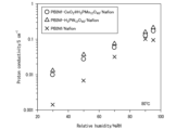
- FIG. 13 is a graph showing the results of measuring the ionic conductivity of the composite electrolyte membrane in Examples 7 and 8 and Comparative Example 2 under conditions of changing the relative humidity while fixing the temperature at 80° C. in a state in which the composite electrolyte membrane was placed in a thermostatic and humidity chamber.
- 1 is a scanning electron microscope image of a cross section of the composite electrolyte membrane obtained in Example 9.
- FIG. 1 is a scanning electron microscope image of a cross section of the composite electrolyte membrane obtained in Example 9.
- FIG. 13 is a graph showing the results of measuring the ionic conductivity of the composite electrolyte membranes obtained in Examples 7 and 9 while controlling the temperature and humidity under conditions in which the relative humidity was fixed at 40% and the temperature was changed in Example 9.
- FIG. 13 is a graph showing the results of measuring the ionic conductivity of the composite electrolyte membrane in Examples 10 and 11 and Comparative Example 2 under conditions of changing the relative humidity while the temperature was fixed at 80° C. in a state in which the composite electrolyte membrane was placed in a thermostatic and humidity chamber.
- the nanofiber adduct according to one embodiment of the present invention comprises a nanofiber and an ion-conductivity imparting agent that interacts with the nanofiber. Specifically, an isopolyacid or heteropolyacid is bonded to the nanofiber as an ion-conductivity imparting agent. The term “bond” will be explained later in the explanation of "interaction.”
- the ion conductivity imparting agent includes an isopolyacid or a heteropolyacid. This includes cases where particles containing only isopolyacid or heteropolyacid, i.e. consisting of only isopolyacid or heteropolyacid, are used as the ion conductivity imparting agent, as well as cases where composite particles including a core consisting of at least one selected from the group consisting of metals having activity in decomposing and eliminating hydrogen peroxide or oxides of said metals, and an outer shell covering the core consisting of an isopolyacid or heteropolyacid are used as the ion conductivity imparting agent.
- the ion conductivity imparting agent in this embodiment contains only isopolyacid or heteropolyacid
- the ion conductivity imparting agent is a particle consisting of only isopolyacid or heteropolyacid.
- the ion conductivity imparting agent mainly exhibits ion conductivity (specifically, proton conductivity), but depending on the type of isopolyacid or heteropolyacid, it also functions as a radical quenching agent, which will be described later.
- the particle size of the particles can be any depending on the isopolyacid or heteropolyacid used, and is not particularly limited as long as it is a particle size that can be bonded to the nanofibers, which will be described later.
- the ion-conductivity imparting agent in this embodiment is preferably a composite particle comprising a core made of at least one selected from the group consisting of metals and oxides of the metals having activity in decomposing and eliminating hydrogen peroxide, and an outer shell made of isopolyacid or heteropolyacid covering the core.
- the core being covered with an outer shell made of isopolyacid or heteropolyacid means, for example, that isopolyacid or heteropolyacid is present on at least a part of the surface of the core so as to cover the core.
- the core and the outer shell are connected by chemically bonding the isopolyacid or heteropolyacid with the components constituting the core.
- the core is covered with isopolyacid or heteropolyacid.
- the ion-conductivity imparting agent made of composite particles exhibits ion conductivity and also functions as a radical quenching agent described later.
- the particle diameter of the particles is arbitrary depending on the isopolyacid or heteropolyacid and the core used, and is not particularly limited as long as it is a particle diameter that can be bonded to the nanofiber described later.
- the radical quenching agent has a function of suppressing the generation of radicals in the electrolyte membrane (including the function of deactivating the generated radicals) as the fuel cell is used, for example, when an electrolyte membrane or composite electrolyte membrane containing the ion conductivity imparting agent in this embodiment is applied to the electrolyte membrane of a fuel cell.
- the radical quenching agent has a function of decomposing and eliminating hydrogen peroxide generated at the electrode (positive electrode). Because hydrogen peroxide is decomposed and eliminated, radical species derived from hydrogen peroxide are not generated.
- the ion conductivity imparting agent in this embodiment functions as a radical quenching agent, it can also function as an antioxidant in the living body.
- Examples of isopolyacids include H2WO4 , H2MoO4 , H6V10O28 , H6Bi12O16 , H8Nb6O19 , and H8Ta6O19 .
- Heteropolyacid is an n- type polyacid in which a heteroatom X is inserted into the metal oxoacid skeleton of an isopolyacid (XaMbOc ) .
- the heteropolyacid is a compound represented by the following structural formula (1): HxAy [ XaMbOc ] .zH2O (1)
- A is a cationic atom
- X is a heteroatom
- M is a metal atom
- a, b, c, x, y, and z are constants.
- y includes 0.
- Examples of the metal atom M include tungsten (W), molybdenum (Mo), vanadium (V), bismuth (Bi), niobium (Nb), and tantalum (Ta).
- Examples of the heteroatom X include phosphorus (P), silicon (Si), germanium (Ge), boron (B), aluminum (Al), cobalt (Co), nickel (Ni), tin (Sn), and lead (Pb).
- heteropolyacids examples include H3PW12O40 , H4SiW12O40 , H3PMo12O40 , H4SiMo12O40 , H4GeW12O40 , H5BW12O40 , H5AlW12O40 , H6CoW12O40 , H6NiW12O40 , and H6P2W18O62 .
- the metal that constitutes the core and has the activity of decomposing and eliminating hydrogen peroxide is preferably at least one selected from the group consisting of titanium (Ti), vanadium (V), chromium (Cr), manganese (Mn), cobalt (Co), nickel (Ni), copper (Cu), zinc (Zn), zirconium (Zr), molybdenum (Mo), tungsten (W), bismuth (Bi), ruthenium (Ru), silver (Ag), gold (Au), cerium (Ce), lanthanum (La), praseodymium (Pr), neodymium (Nd), samarium (Sm), europium (Eu), gadolinium (Gd), terbium (Tb), holmium (Ho), ytterbium (Yb), etc.
- the metal is preferably one metal selected from the group, or an alloy consisting of two or more metals selected from the group.
- Metal oxides having the activity of decomposing and eliminating hydrogen peroxide include oxides of one or two metals selected from the above group.
- Specific examples of metal oxides containing one metal include cerium oxide ( CeO2 ), manganese dioxide ( MnO2 ), zinc oxide (ZnO), vanadium oxide ( V2O5 ), copper oxide (CuO), nickel oxide (NiO), cobalt oxide ( Co3O4 ), titanium oxide ( TiO2 ), bismuth oxide ( Bi2O3 ) , zirconium oxide ( ZrO2 ), lanthanum oxide ( La2O3 ) , and praseodymium oxide ( Pr6O11 ).
- metal oxides containing two kinds of metals include Ce x Mn (1-X) O 2 , Ce x Zr (1-X) O 2 , Ce x Pr (1-X) O 2 , Ce x Eu (1-X) O 2 , Ce x Yb (1-X) O 2 , Ce x Gd (1-X) O 2 , and Ce x Sm (1-X) O 2 (x is a number greater than 0). That is, the metal oxide is preferably an oxide of one metal selected from the above group, or a composite oxide of two or more metals selected from the above group. In the present invention, the core is preferably made of a combination of two or more of the above metals or metal oxides.
- the core preferably contains manganese or manganese oxide, or bismuth (bismuth or bismuth oxide) as an essential component.
- a core containing manganese or manganese oxide, or bismuth as an essential component and further containing one or more other metals or metal oxides, particularly three or more metals and/or metal oxides is used as the core, it has a particularly high radical quenching property and is not easily dissolved in strong acids, so that the effect of performance being less likely to deteriorate can be obtained.
- the core contains manganese or manganese oxide as an essential component, and the manganese content (content of Mn atoms) is preferably 3 to 65 wt% of the entire core from the viewpoint of the balance between ion conductivity and radical quenching performance, more preferably 15 to 35 wt%, and most preferably 17 to 35 wt%. Furthermore, when the core is formed of a ternary or higher component containing three or more metal elements, it is preferable because it is particularly excellent in acid resistance (insolubility in acidic solutions) and the radical quenching performance and therefore the ion conductivity are unlikely to deteriorate for a long period of time.
- the content of Bi is preferably 10 to 90 wt%, and more preferably 30 to 65 wt%.
- both Mn and Bi it is preferable that both of them satisfy the above-mentioned content range because, as shown in the examples described later, it is also excellent in acid resistance (insolubility in acidic solutions) and is also excellent in terms of radical quenching performance and ion conductivity.
- the ion-conductivity imparting agent include the following: In the following examples, in the form of X@Y, X represents a core and Y represents an outer shell.
- H3PW12O40 H3PMo12O40 , H4SiW12O40 , H4SiMo12O40 , (Mono- or bi-component ion-conductivity imparting agent having a metal or metal oxide core) ZrO 2 @H 3 PW 12 O 40 , ZrO 2 @H 3 PMo 12 O 40 , ZrO 2 @H 4 SiW 12 O 40 , ZrO 2 @H 4 SiMo 12 O 40 , CeO 2 @H 3 PW 12 O 40 , Ce0.85Zr0.15O2@H3PW12O40 (In this core structure, a composite oxide of cerium oxide and zirconium oxide is considered to be formed.
- the ratio of metal oxide is determined by the number of oxygen atoms and the number of each metal atom.
- Method of manufacturing ion-conductivity imparting agent An example of a method of manufacturing an ion-conductivity imparting agent including the core and the outer shell is a method including a coating step of coating at least one type of particle selected from the group consisting of the metal and the metal oxide with an isopolyacid or heteropolyacid.
- a coating step for example, an isopolyacid or heteropolyacid is added to a dispersion containing nanoparticles of the metal oxide, and the dispersion is dialyzed to obtain nanoparticles coated with the isopolyacid or heteropolyacid.
- the calcination temperature when manufacturing the metal oxide constituting the outer shell is preferably 400°C or higher, more preferably 600°C or higher, and most preferably 800°C or higher. Since radical quenching performance may be improved by preparing an ion-conductivity imparting agent using a metal oxide calcined at this temperature or higher, it is preferable to calcinate within the above temperature range.
- the nanofiber is made of a fibrous polymer compound (single fiber) with a diameter of less than 1 ⁇ m.
- the nanofiber may be used as a fiber assembly (nanofiber mat) in which voids exist between the single fibers.
- the nanofiber can be used, for example, as a nanofiber mat. It is preferable that the thickness of the nanofiber mat is 40 ⁇ m or less.
- voids exist between the single fibers, and the porosity is preferably such that the ratio of the volume of the voids to the volume of the entire nanofiber mat is 80 vol% or more.
- the polymeric compounds constituting the nanofibers are not particularly limited as long as they can form nanofibers, and in this embodiment, they may be any of basic polymers, acidic polymers, and neutral polymers.
- polybenzimidazole, polyvinyl alcohol, sulfonated polyimide, polyacrylonitrile, etc. are preferred, and polymeric compounds containing basic groups are particularly preferred.
- nanofibers specific examples and manufacturing methods, etc.
- Commercially available products such as Nafion (registered trademark) can also be used.
- nanofiber forms include porous nanofibers and hollow core-sheath nanofibers.
- the nanofibers in this embodiment can be manufactured, for example, by an electrospinning method in which a high voltage is applied to a polymer compound solution or a polymer compound in a molten state to spin fibers.
- Nanofiber adduct the interaction between the ion-conductivity imparting agent and the nanofiber means that, for example, when a compound having basic groups is used as the polymer compound that constitutes the nanofiber, the basic groups present in the polymer compound bond with the polyacid that constitutes the ion-conductivity imparting agent through multipoint acid-base interaction or the like. This results in a strong bond between the ion-conductivity imparting agent and the nanofiber, and even if the nanofiber adduct is washed with warm water, the ion-conductivity imparting agent does not easily separate from the nanofiber.
- the ion-conductivity imparting agent is present by being bound to the surface of the nanofiber.
- the ion-conductivity imparting agent may be present on the outer surface of the nanofiber.
- the ion-conductivity imparting agent may be present on the pore surface of the nanofiber.
- the ion-conductivity imparting agent may be present on the hollow surface of the nanofiber.
- the ion-conductivity imparting agent may be present inside the nanofiber.
- Methods of manufacturing the nanofiber adduct of this embodiment include, for example, a method of immersing a nanofiber in a solution containing an ion-conductivity imparting agent to allow the ion-conductivity imparting agent to interact with the nanofiber.
- Methods of manufacturing the nanofiber adduct of this embodiment include, for example, a method of electrospinning nanofibers from a mixed solution in which an ion-conductivity imparting agent is added to a solution containing a polymer compound that is the raw material for the nanofiber when manufacturing the nanofiber. With this method, nanofibers can be obtained in which the ion-conductivity imparting agent is present inside the nanofiber (naturally, it is also present on the outer surface of the nanofiber), regardless of the shape of the nanofiber.
- the nanofiber adduct of this embodiment is composed of nanofibers and an ion-conducting agent that interacts with the nanofibers. Since the ion-conducting agent contains isopolyacid or heteropolyacid, when applied to the electrolyte membrane of a fuel cell, the nanofiber adduct has excellent ion conductivity.
- nanofiber adduct containing an ion-conducting agent that is composed of a core made of at least one selected from the group consisting of metals or metal oxides that have activity in eliminating hydrogen peroxide and an outer shell made of isopolyacid or heteropolyacid that covers the core is applied to the electrolyte membrane of a fuel cell, the nanofiber adduct has excellent function of decomposing and eliminating hydrogen peroxide generated at the electrode (positive electrode) for a long period of time.
- the nanofiber adduct of this embodiment when the nanofiber adduct of this embodiment is applied to the electrolyte membrane of a fuel cell, not only can the decrease in ion conductivity be suppressed, but mechanical and chemical deterioration of the electrolyte membrane caused by radical species derived from hydrogen peroxide generated at the electrode (positive electrode) can also be suppressed.
- the electrolyte membrane according to one embodiment of the present invention contains an ion-conductivity imparting agent and an ion-conductive polymer compound.
- the ionic conductivity imparting agent in this embodiment may be the same as the ionic conductivity imparting agent in the nanofiber adduct in one embodiment of the present invention.
- Ion-conductive polymer compound The ion-conductive polymer compound in this embodiment is a matrix that fills the gaps between the ion-conductivity imparting agent particles dispersed in the electrolyte membrane.
- ion-conductive polymer compounds include Nafion (registered trademark), sulfonated aromatic polymers, and phosphonated aromatic polymers.
- Methods of manufacturing the electrolyte membrane of this embodiment include, for example, a method of adding a dispersion in which an ion-conductivity imparting agent is dispersed in a solvent to a solution containing an ion-conductive polymer compound, and evaporating the solvent.
- Methods of manufacturing the electrolyte membrane of this embodiment include, for example, a method of applying a coating liquid containing an ion-conductivity imparting agent and an ion-conductive polymer compound to a constant liquid film thickness using a film applicator or bar coater, or a method of applying the coating liquid while supplying it using a die coater.
- the electrolyte membrane of this embodiment contains an ion conductivity imparting agent containing isopolyacid or heteropolyacid, and therefore has ion conductivity due to the ion conductivity imparting agent.
- the ion conductivity imparting agent contains an isopolyacid or heteropolyacid having hydrogen peroxide elimination activity, or when the ion conductivity imparting agent contains a core made of at least one selected from the group consisting of metals or metal oxides having hydrogen peroxide elimination activity, and an outer shell made of isopolyacid or heteropolyacid covering the core
- the electrolyte membrane of this embodiment can suppress mechanical and chemical deterioration of the electrolyte membrane caused by radical reactions derived from hydrogen peroxide generated at the electrode (positive electrode) while maintaining ion conductivity.
- the electrolyte membrane of this embodiment when the electrolyte membrane of this embodiment is applied to the electrolyte membrane of a fuel cell, not only is the decrease in ion conductivity suppressed, but the membrane is also excellent in the function of decomposing and eliminating hydrogen peroxide generated at the electrode (positive electrode).
- the composite electrolyte membrane according to one embodiment of the present invention further comprises nanofibers in addition to the electrolyte membrane according to one embodiment of the present invention.
- Nanofibers examples of nanofibers in this embodiment include nanofibers similar to those in the nanofiber adduct of one embodiment of the present invention.
- the ionic conductivity imparting agent in this embodiment may be the same as the ionic conductivity imparting agent in the nanofiber adduct in one embodiment of the present invention.
- the nanofibers may not interact with the ion-conductivity imparting agent, or may interact with the ion-conductivity imparting agent.
- the nanofibers and the ion-conductivity imparting agent are simply dispersed in the composite electrolyte membrane.
- the nanofibers and the ion-conductivity imparting agent may form a nanofiber adduct in the composite electrolyte membrane similar to the nanofiber adduct of one embodiment of the present invention.
- the nanofibers and the ion-conductivity imparting agent may be bonded to each other through a multipoint acid-base interaction between a basic group present in the polymer compound constituting the nanofiber and a heteropolyacid contained in the ion-conductivity imparting agent. This allows the nanofibers and the ion-conductivity imparting agent to be firmly bonded together, and the ion-conductivity imparting agent does not easily separate from the nanofibers in the composite electrolyte membrane.
- the ion-conductivity imparting agent is, for example, bonded to the surface of the nanofiber. Furthermore, when the nanofiber is a porous nanofiber, the ion-conductivity imparting agent may be present inside the pores of the nanofiber. Furthermore, when the nanofiber is a hollow sheath-core nanofiber, the ion-conductivity imparting agent may be present inside the hollow portion of the nanofiber. Furthermore, even if the nanofiber is not a hollow sheath-core nanofiber, the ion-conductivity imparting agent may be present inside the nanofiber.
- Methods of manufacturing the composite electrolyte membrane of this embodiment include, for example, a method of adding a dispersion of an ion-conductivity imparting agent and a solution containing an ion-conductive polymer compound to nanofibers and evaporating the solvent.
- Methods of manufacturing the composite electrolyte membrane of this embodiment include, for example, a method of applying a coating liquid containing an ion-conductivity imparting agent and an ion-conductive polymer compound to nanofibers with a constant liquid film thickness using a film applicator or bar coater, or a method of applying the coating liquid while supplying it using a die coater.
- the composite electrolyte membrane of this embodiment further contains nanofibers in addition to the electrolyte membrane according to one embodiment of the present invention, and therefore has an excellent function of decomposing and eliminating hydrogen peroxide generated at the electrode (positive electrode) over a long period of time. Therefore, when the composite electrolyte membrane of this embodiment is applied to the electrolyte membrane of a fuel cell, not only can the decrease in ion conductivity be suppressed, but mechanical and chemical deterioration of the composite electrolyte membrane caused by radical reactions originating from hydrogen peroxide generated at the electrode (positive electrode) can also be suppressed.
- a composite electrolyte membrane according to one embodiment of the present invention includes a nanofiber adduct in which an ion-conductivity imparting agent is bonded to a nanofiber, and an ion-conductive polymer compound.
- Nanofiber adduct The nanofiber adduct in this embodiment may be the same as the nanofiber in the nanofiber adduct according to one embodiment of the present invention.
- the ion-conductive polymer compound in this embodiment is a matrix that fills the gaps between the nanofiber adducts.
- Examples of the ion-conductive polymer compound include the same ion-conductive polymer compounds as those in the electrolyte membrane according to one embodiment of the present invention.
- Manufacturing method of composite electrolyte membrane An example of a method for manufacturing a composite electrolyte membrane is to add a solution containing an ion-conductive polymer compound to the nanofiber adduct and evaporate the solvent. In addition, an example of a method for manufacturing the composite electrolyte membrane of this embodiment is to apply a coating liquid containing an ion-conductive polymer compound to the nanofiber adduct using a film applicator or bar coater to a constant liquid film thickness, or to apply the coating liquid while supplying it using a die coater. The dispersion may contain the nanofibers and the ion-conductive polymer compound.
- the composite electrolyte membrane of this embodiment contains an ion conductivity imparting agent containing an isopolyacid or heteropolyacid, and has ion conductivity due to the ion conductivity imparting agent.
- the composite electrolyte membrane of this embodiment has both ion conductivity and activity to decompose and eliminate hydrogen peroxide.
- the composite electrolyte membrane of this embodiment when the composite electrolyte membrane of this embodiment is applied to the electrolyte membrane of a fuel cell, not only is it possible to suppress the decrease in ion conductivity, but it is also possible to suppress mechanical and chemical deterioration of the composite electrolyte membrane caused by radical reactions derived from hydrogen peroxide generated at the electrode (positive electrode) over a long period of time.
- a fuel cell according to one embodiment of the present invention comprises a positive electrode, a negative electrode, and an electrolyte membrane (solid polymer membrane) disposed between the positive electrode and the negative electrode, and the electrolyte membrane (solid polymer membrane) is the electrolyte membrane or composite electrolyte membrane according to one embodiment of the present invention described above.
- Fuel cells have a structure in which a solid polymer membrane is sandwiched between a positive electrode (air electrode) and a negative electrode (fuel electrode).
- positive and negative electrodes include electrode plates made of carbon carrying a platinum catalyst.
- the fuel cell of this embodiment comprises a positive electrode, a negative electrode, and a solid polymer membrane disposed between the positive electrode and the negative electrode.
- the solid polymer membrane is the electrolyte membrane or composite electrolyte membrane of the above-mentioned embodiment, and therefore has an excellent function of decomposing and eliminating hydrogen peroxide generated at the electrode (cathode) without reducing ion conductivity. Therefore, the fuel cell of this embodiment can suppress, over a long period of time, the reduction in ion conductivity of the solid polymer membrane, and the mechanical and chemical deterioration of the solid polymer membrane caused by radical species derived from hydrogen peroxide generated at the electrode (cathode).
- Example 1 "Preparation of ion-conductivity imparting agent" 100 mg of fine powder of metal, alloy, single metal oxide, or composite metal oxide was dispersed in 5 mL of water. 150 mg of isopolyacid or heteropolyacid was added to the dispersion and ultrasonically irradiated for 10 minutes. Free isopolyacid or heteropolyacid was removed by centrifuging or dialysis three times from the dispersion, and the dispersion was then vacuum dried at 60°C to obtain an ion-conductivity imparting agent.
- Test method 0.5 mg to 50 mg of ion conductivity imparting agent was added to 5 mL of hydrogen peroxide solution (30 mass%) at 50°C and stirred, whereby hydrogen peroxide was decomposed by the ion conductivity imparting agent and oxygen was generated. The amount of oxygen generated was measured using a gas burette.
- Example 2 "Preparation of nanofiber adduct"
- 10 g of phosphotungstic acid n-hydrate H 3 PW 12 O 40.nH 2 O
- 10 mL of water To prepare an aqueous solution of the ion conductivity imparting agent.
- PBINf polybenzimidazole nanofiber
- the PBINf was washed three times with water, immersed three times in 500 mL of hot water at 80° C. for heating and washing, spread on a Teflon (registered trademark) plate, air-dried, and then vacuum-dried at 80° C. to obtain a nanofiber adduct.
- the amount of the ion conductivity imparting agent bound to the PBINf was estimated from the mass increase before and after the treatment.
- the amount of the ion-conductivity imparting agent bound was 3.5 ⁇ 0.2% by mass based on the total mass of the nanofiber adduct.
- FIG. 1 shows the UV-Visible diffuse reflectance spectrum of the nanofiber adduct obtained in Example 2.
- FIG. 1 also shows the UV-Visible diffuse reflectance spectrum of the nanofiber not containing an ion-conductivity-imparting agent.
- the nanofiber adduct obtained in Example 2 is shown as PBINf-H 3 PW 12 O 40 adduct, and the PBI nanofiber not containing an ion-conductivity-imparting agent is shown as PBINf.
- Example 3 "Preparation of nanofiber adduct" 7 mg of polybenzimidazole nanofiber (PBINf) having a nanofiber mat thickness of 30 ⁇ m and a porosity of 90% was immersed in 10 mL of a dispersion of an ion-conductivity imparting agent (CeO 2 @H 3 PMo 12 O 40 ) heated to 80° C. for 1 hour. After immersion in the aqueous solution, the PBINf was washed three times with water, immersed three times in 500 mL of hot water at 80° C. and heated and washed, spread on a Teflon (registered trademark) plate, air-dried, and then vacuum-dried at 60° C.
- PBINf polybenzimidazole nanofiber
- the amount of the ion-conductivity imparting agent bound to the PBINf was estimated from the increase in mass before and after the treatment.
- the amount of the ion-conductivity imparting agent bound was 7.7 ⁇ 0.1% by mass with respect to the total mass of the nanofiber adduct.
- FIG. 2 shows the UV-Visible diffuse reflectance spectrum of the nanofiber adduct obtained in Example 3.
- FIG. 2 also shows the UV-Visible diffuse reflectance spectrum of the PBI nanofiber not containing an ion-conductivity imparting agent.
- the nanofiber adduct obtained in Example 3 is shown as PBINf-CeO 2 @H 3 PMo 12 O 40 adduct, and the PBI nanofiber not containing an ion-conductivity imparting agent is shown as PBINf.
- tungstosilicic acid n-hydrate H 4 SiW 12 O 40 nH 2 O
- FIG. 3 shows a scanning electron microscope (SEM) image of the cross section of the electrolyte membrane obtained in Example 4.
- Figure 3 shows that a dense electrolyte membrane without voids was formed.
- the ionic conductivity of the obtained electrolyte membrane was measured by the following method. First, the electrolyte membrane was cut into a strip of 1 cm width to prepare a sample membrane. The sample membrane was placed on two 4 mm wide platinum plates placed 1 cm apart on a Teflon plate. Using another Teflon plate, the sample membrane and the platinum plate were sandwiched between two Teflon plates, and the whole was fixed by clamping with a clip. An LCR meter was used to connect the lead wire attached to the platinum plate, and an alternating current of 1 V was applied to the sample membrane while changing the frequency from 50 Hz to 500 kHz, and the response of the current and phase angle in the sample membrane was measured.
- the ionic conductivity of the electrolyte membrane was obtained from the diameter of the semicircle of the Cole-Cole plot.
- the ionic conductivity of the electrolyte membrane was measured under conditions where the sample membrane was placed in a thermostatic chamber and the temperature was fixed at 80° C. and the relative humidity was changed.
- the results are shown in FIG. 4. 4 shows the ionic conductivity of the electrolyte membrane containing Bi 2 O 3 @H 3 PW 12 O 40 and Nafion (registered trademark) obtained in Example 5, and the ionic conductivity of the Nafion monolayer membrane obtained in Comparative Example 1.
- FIG. 4 shows the ionic conductivity of the electrolyte membrane containing Bi 2 O 3 @H 3 PW 12 O 40 and Nafion (registered trademark) obtained in Example 5
- FIG. 4 shows the ionic conductivity of the electrolyte membrane containing Bi 2 O 3 @H 3 P
- Example 4 the electrolyte membrane obtained in Example 4 is shown as H 4 SiW 12 O 40 /Nafion, the electrolyte membrane containing Bi 2 O 3 @H 3 PW 12 O 40 and Nafion (registered trademark) obtained in Example 5 is shown as Bi 2 O 3 @H 3 PW 12 O 40 /Nafion, and the Nafion monolayer membrane obtained in Comparative Example 1 is shown as recast Nafion. From the results shown in FIG. 4, it was found that the electrolyte membrane of Example 4 exhibited ionic conductivity equivalent to that of the Nafion monolayer membrane (recast Nafion) of Comparative Example 1.
- Example 5 Preparation of Electrolyte Membrane An electrolyte membrane of Example 5 was obtained in the same manner as in Example 4, except that bismuth oxide@phosphotungstic acid (Bi 2 O 3 @H 3 PW 12 O 40 ) was used as the ion-conductivity imparting agent.
- bismuth oxide@phosphotungstic acid Ba 2 O 3 @H 3 PW 12 O 40
- FIG. 5 shows a scanning electron microscope (SEM) image of the cross section of the electrolyte membrane obtained in Example 5.
- Figure 5 shows that a dense electrolyte membrane without voids was formed.
- Example 6 Preparation of Composite Electrolyte Membrane A 20 mass% Nafion (registered trademark) dispersion was applied to the nanofiber adduct (PBINf-H 3 PW 12 O 40 ) obtained in Example 2 using an applicator, and then the mixture was naturally dried in the atmosphere and then vacuum dried at 60° C. to obtain the composite electrolyte membrane of Example 6.
- PBINf-H 3 PW 12 O 40 nanofiber adduct
- FIG. 6 shows the UV-Visible absorption spectrum of the composite electrolyte membrane obtained in Example 6.
- FIG. 6 also shows the UV-Visible absorption spectrum of the Nafion monolayer membrane (recast Nafion) of Comparative Example 1.
- the composite electrolyte membrane obtained in Example 6 is shown as PBINf-H 3 PW 12 O 40 /Nafion, and the Nafion monolayer membrane obtained in Comparative Example 1 is shown as recast Nafion.
- Example 7 Preparation of Composite Electrolyte Membrane A nanofiber adduct (PBINf-H 3 PW 12 O 40 ) was obtained in the same manner as in Example 2, except that phosphotungstic acid n-hydrate (H 3 PW 12 O 40.nH 2 O) was used as the ion conductivity imparting agent and the amount of the ion conductivity imparting agent bound was 7.0 mass% relative to the total mass of the nanofiber adduct.
- the composite electrolyte membrane of Example 7 was obtained from the obtained nanofiber adduct by the same method as in Example 6.
- FIG. 7 shows the ionic conductivity of the composite electrolyte membrane containing the nanofiber adduct (PBINf-CeO 2 @H 3 PMo 12 O 40 ) and Nafion (registered trademark) obtained in Example 8, and the ionic conductivity of the composite electrolyte membrane containing the PBIN nanofiber and Nafion (registered trademark) obtained in Comparative Example 2.
- PBINf-CeO 2 @H 3 PMo 12 O 40 nanofiber adduct
- Nafion registered trademark
- Example 7 the composite electrolyte membrane obtained in Example 7 is shown as PBINf-H 3 PW 12 O 40 /Nafion
- the composite electrolyte membrane obtained in Example 8 is shown as PBINf-CeO 2 @H 3 PMo 12 O 40 /Nafion
- the composite electrolyte membrane containing the PBIN nanofiber and Nafion (registered trademark) obtained in Comparative Example 2 is shown as PBINf/Nafion. From the results shown in FIG. 7, it was found that the composite electrolyte membrane of Example 7 exhibited higher ionic conductivity than the composite electrolyte membrane of Comparative Example 2 containing only unmodified PBI nanofibers.
- Example 8 Preparation of Composite Electrolyte Membrane The nanofiber adduct (PBINf-CeO 2 @H 3 PMo 12 O 40 ) obtained in Example 3 was used in the same manner as in Example 6 to obtain a composite electrolyte membrane of Example 8.
- Example 9 Preparation of Composite Electrolyte Membrane A nanofiber adduct (PBINf-H 2 WO 4 ) was obtained in the same manner as in Example 2, except that tungstic acid (H 2 WO 4 ) was used as the ion-conductivity imparting agent and the amount of the ion-conductivity imparting agent bound was 27 mass % relative to the total mass of the nanofiber adduct.
- the composite electrolyte membrane of Example 9 was obtained from the obtained nanofiber adduct by the same method as in Example 6 .
- FIG. 8 shows a scanning electron microscope (SEM) image of the cross section of the composite electrolyte membrane obtained in Example 9. From Figure 8, the nanofibers appear bright, which confirmed that the nanofibers were modified with tungstic acid contained in the ion conductivity imparting agent. It was also found that a dense composite electrolyte membrane was formed.
- the ionic conductivity of the composite electrolyte membranes of Examples 7 and 9 was measured while controlling the temperature and humidity under conditions of a fixed relative humidity of 40% and varying the temperature. The results are shown in FIG. 9.
- the composite electrolyte membrane obtained in Example 7 is shown as PBINf-H 3 PW 12 O 40 /Nafion
- the composite electrolyte membrane obtained in Example 9 is shown as PBINf-H 2 WO 4 /Nafion. From the results shown in FIG. 9, it was found that the composite electrolyte membranes of Examples 7 and 9 exhibited high ionic conductivity on the order of 10 -3 Scm -1 to 10 -1 Scm -1 under both conditions.
- Example 10 Preparation of Composite Electrolyte Membrane A dispersion of an ion-conductivity imparting agent (H 4 SiW 12 O 40.nH 2 O) dispersed in a 20 mass % Nafion (registered trademark) dispersion was applied to unmodified PBI nanofibers with an applicator, and then the coating was allowed to dry naturally in the air and then vacuum dried at 60° C. to obtain a composite electrolyte membrane of Example 10.
- an ion-conductivity imparting agent H 4 SiW 12 O 40.nH 2 O
- Nafion registered trademark
- Fig. 10 also shows the ionic conductivity of the composite electrolyte membrane containing Bi2O3 @ H3PW12O40 , PBI nanofibers , and Nafion (registered trademark) obtained in Example 11, and the ionic conductivity of the composite electrolyte membrane containing PBI nanofibers and Nafion (registered trademark) obtained in Comparative Example 2.
- Example 10 the composite electrolyte membrane obtained in Example 10 is shown as H 4 SiW 12 O 40 /PBINf/Nafion
- the composite electrolyte membrane obtained in Example 11 containing Bi 2 O 3 @H 3 PW 12 O 40 , PBI nanofibers, and Nafion (registered trademark) is shown as Bi 2 O 3 @H 3 PW 12 O 40 /PBINf/Nafion
- the composite electrolyte membrane obtained in Comparative Example 2 containing PBINf and Nafion (registered trademark) is shown as PBINf/Nafion. From the results shown in FIG. 10, it was found that the composite electrolyte membrane of Example 10 exhibited higher ionic conductivity than the composite electrolyte membrane of Comparative Example 2 containing only unmodified PBI nanofibers.
- Example 11 Preparation of Composite Electrolyte Membrane
- the ion-conductivity imparting agent ( Bi2O3 @ H3PW12O40 ) obtained in Example 5 was dispersed in a 20 mass% Nafion (registered trademark) dispersion, and the dispersion was applied to unmodified PBI nanofibers in the same manner as in Example 10 to obtain a composite electrolyte membrane of Example 11.
- Example 12 "Preparation of ion-conductive agent" Metal materials (raw materials for obtaining the components shown to the left of the @ in Table 2) were mixed in a conventional manner and sintered at the sintering temperature shown in Table 2 for a predetermined time (varies depending on the metal raw material) to obtain a metal oxide. The obtained metal oxide was finely powdered, and 100 mg of the obtained fine powder was dispersed in 5 mL of water. 150 mg of isopolyacid or heteropolyacid shown in Table 2 (right side of the @) was added to the dispersion and ultrasonically irradiated for 10 minutes.
- the ion-conductivity imparting agent When the ion-conductivity imparting agent was dissolved by visual inspection and the remaining agent could not be confirmed, it is indicated by ⁇ in the table, and when the remaining agent was confirmed, it is indicated by ⁇ in the table.
- the weight percentage of Mn element and Bi element in the core (metal oxide) of each obtained ion-conductivity imparting agent is also shown in each table.
Landscapes
- Fuel Cell (AREA)
Priority Applications (1)
| Application Number | Priority Date | Filing Date | Title |
|---|---|---|---|
| JP2025524885A JPWO2024248102A1 (https=) | 2023-06-02 | 2024-05-30 |
Applications Claiming Priority (2)
| Application Number | Priority Date | Filing Date | Title |
|---|---|---|---|
| JP2023091800 | 2023-06-02 | ||
| JP2023-091800 | 2023-06-02 |
Publications (1)
| Publication Number | Publication Date |
|---|---|
| WO2024248102A1 true WO2024248102A1 (ja) | 2024-12-05 |
Family
ID=93657631
Family Applications (1)
| Application Number | Title | Priority Date | Filing Date |
|---|---|---|---|
| PCT/JP2024/019917 Ceased WO2024248102A1 (ja) | 2023-06-02 | 2024-05-30 | ナノファイバー付加体、電解質膜、複合電解質膜、燃料電池およびイオン伝導性付加剤 |
Country Status (2)
| Country | Link |
|---|---|
| JP (1) | JPWO2024248102A1 (https=) |
| WO (1) | WO2024248102A1 (https=) |
Citations (4)
| Publication number | Priority date | Publication date | Assignee | Title |
|---|---|---|---|---|
| JP2010257771A (ja) * | 2009-04-24 | 2010-11-11 | Toyota Central R&D Labs Inc | 高耐久性電解質膜、電極及び固体高分子型燃料電池 |
| CN105655603A (zh) * | 2015-12-31 | 2016-06-08 | 北京化工大学 | 一种燃料电池催化剂及其制备方法 |
| JP2017532716A (ja) * | 2014-08-04 | 2017-11-02 | ジョンソン、マッセイ、フュエル、セルズ、リミテッドJohnson Matthey Fuel Cells Limited | 膜 |
| CN108754545A (zh) * | 2018-05-15 | 2018-11-06 | 昆明理工大学 | 一种杂多酸修饰的碳纳米管和/或石墨烯增强铅基复合阳极制备方法 |
-
2024
- 2024-05-30 JP JP2025524885A patent/JPWO2024248102A1/ja active Pending
- 2024-05-30 WO PCT/JP2024/019917 patent/WO2024248102A1/ja not_active Ceased
Patent Citations (4)
| Publication number | Priority date | Publication date | Assignee | Title |
|---|---|---|---|---|
| JP2010257771A (ja) * | 2009-04-24 | 2010-11-11 | Toyota Central R&D Labs Inc | 高耐久性電解質膜、電極及び固体高分子型燃料電池 |
| JP2017532716A (ja) * | 2014-08-04 | 2017-11-02 | ジョンソン、マッセイ、フュエル、セルズ、リミテッドJohnson Matthey Fuel Cells Limited | 膜 |
| CN105655603A (zh) * | 2015-12-31 | 2016-06-08 | 北京化工大学 | 一种燃料电池催化剂及其制备方法 |
| CN108754545A (zh) * | 2018-05-15 | 2018-11-06 | 昆明理工大学 | 一种杂多酸修饰的碳纳米管和/或石墨烯增强铅基复合阳极制备方法 |
Also Published As
| Publication number | Publication date |
|---|---|
| JPWO2024248102A1 (https=) | 2024-12-05 |
Similar Documents
| Publication | Publication Date | Title |
|---|---|---|
| CA2924326C (en) | Production method of electrode catalyst | |
| JP7101119B2 (ja) | 触媒 | |
| JP2022527700A (ja) | ラジカルスカベンジャー、その製造方法、及びそれを含む膜電極組立体 | |
| KR20100098528A (ko) | 고 안정성 연료 전지 막 및 그의 제조 방법 | |
| JP5730751B2 (ja) | 燃料電池用白金・チタン酸化物・チタンカーバイド複合触媒及びその製造方法、並びに当該複合触媒を用いた燃料電池用膜・電極接合体 | |
| JP4461088B2 (ja) | 燃料電池用電極、膜電極複合体及び燃料電池 | |
| EP1345675A1 (de) | Kationen-/protonenleitende, mit einer ionischen flüssigkeit infiltrierte keramische membran, verfahren zu deren herstellung und die verwendung der membran | |
| WO2015169786A1 (en) | Method for producing and controlling the morphology of metal-oxide nanofiber and/or nanotube catalysts | |
| JP2008034300A (ja) | 燃料電池用電極、膜電極複合体および燃料電池、ならびにそれらの製造法 | |
| KR100639284B1 (ko) | 양성자 전도성 고체 전해질, 양성자 전도성 막, 연료전지용 전극, 막 전극 조립품 및 연료 전지 | |
| CA2926513C (en) | Electrode catalyst | |
| CA2924306A1 (en) | Electrode catalyst having a core-shell structure | |
| JP4625658B2 (ja) | 燃料電池用電極、膜電極複合体及び燃料電池 | |
| WO2024248102A1 (ja) | ナノファイバー付加体、電解質膜、複合電解質膜、燃料電池およびイオン伝導性付加剤 | |
| Seepana et al. | Design and synthesis of highly stable poly (tetrafluoroethylene)-zirconium phosphate (PTFE-ZrP) ion-exchange membrane for vanadium redox flow battery (VRFB) | |
| KR100786423B1 (ko) | 전해질막, 전극 및 연료 전지 | |
| Liang et al. | Effect of MgO and Fe2O3 dual sintering aids on the microstructure and electrochemical performance of the solid state Gd0. 2Ce0. 8O2-δ electrolyte in intermediate-temperature solid oxide fuel cells | |
| JP2011096633A (ja) | プロトン伝導性電解質膜、及びそれを用いた、触媒層−電解質膜積層体、膜−電極接合体及び燃料電池、並びにその製造方法 | |
| CN114597462A (zh) | 对称型固体氧化物电池 | |
| JP4496119B2 (ja) | 燃料電池用プロトン伝導性膜、膜電極複合体及び燃料電池 | |
| Yaowarat et al. | Highly durable silica coated Pt/Cs with different surfactant types for proton exchange membrane fuel cell applications | |
| JP5568111B2 (ja) | 固体高分子型燃料電池 | |
| JP7121175B1 (ja) | 電解質膜及び燃料電池 | |
| JP2026042736A (ja) | 固体高分子形燃料電池及び水電解装置 | |
| JP5090717B2 (ja) | 固体高分子型燃料電池 |
Legal Events
| Date | Code | Title | Description |
|---|---|---|---|
| 121 | Ep: the epo has been informed by wipo that ep was designated in this application |
Ref document number: 24815582 Country of ref document: EP Kind code of ref document: A1 |
|
| ENP | Entry into the national phase |
Ref document number: 2025524885 Country of ref document: JP Kind code of ref document: A |
|
| NENP | Non-entry into the national phase |
Ref country code: DE |