WO2024247693A1 - 表示パネル格納構造、電子機器、並びに表示パネル格納方法 - Google Patents
表示パネル格納構造、電子機器、並びに表示パネル格納方法 Download PDFInfo
- Publication number
- WO2024247693A1 WO2024247693A1 PCT/JP2024/017634 JP2024017634W WO2024247693A1 WO 2024247693 A1 WO2024247693 A1 WO 2024247693A1 JP 2024017634 W JP2024017634 W JP 2024017634W WO 2024247693 A1 WO2024247693 A1 WO 2024247693A1
- Authority
- WO
- WIPO (PCT)
- Prior art keywords
- display panel
- tongue
- panel
- peripheral wall
- tongue piece
- Prior art date
- Legal status (The legal status is an assumption and is not a legal conclusion. Google has not performed a legal analysis and makes no representation as to the accuracy of the status listed.)
- Ceased
Links
Images





Classifications
-
- F—MECHANICAL ENGINEERING; LIGHTING; HEATING; WEAPONS; BLASTING
- F16—ENGINEERING ELEMENTS AND UNITS; GENERAL MEASURES FOR PRODUCING AND MAINTAINING EFFECTIVE FUNCTIONING OF MACHINES OR INSTALLATIONS; THERMAL INSULATION IN GENERAL
- F16B—DEVICES FOR FASTENING OR SECURING CONSTRUCTIONAL ELEMENTS OR MACHINE PARTS TOGETHER, e.g. NAILS, BOLTS, CIRCLIPS, CLAMPS, CLIPS OR WEDGES; JOINTS OR JOINTING
- F16B5/00—Joining sheets or plates, e.g. panels, to one another or to strips or bars parallel to them
- F16B5/10—Joining sheets or plates, e.g. panels, to one another or to strips or bars parallel to them by means of bayonet connections
-
- G—PHYSICS
- G02—OPTICS
- G02F—OPTICAL DEVICES OR ARRANGEMENTS FOR THE CONTROL OF LIGHT BY MODIFICATION OF THE OPTICAL PROPERTIES OF THE MEDIA OF THE ELEMENTS INVOLVED THEREIN; NON-LINEAR OPTICS; FREQUENCY-CHANGING OF LIGHT; OPTICAL LOGIC ELEMENTS; OPTICAL ANALOGUE/DIGITAL CONVERTERS
- G02F1/00—Devices or arrangements for the control of the intensity, colour, phase, polarisation or direction of light arriving from an independent light source, e.g. switching, gating or modulating; Non-linear optics
- G02F1/01—Devices or arrangements for the control of the intensity, colour, phase, polarisation or direction of light arriving from an independent light source, e.g. switching, gating or modulating; Non-linear optics for the control of the intensity, phase, polarisation or colour
- G02F1/13—Devices or arrangements for the control of the intensity, colour, phase, polarisation or direction of light arriving from an independent light source, e.g. switching, gating or modulating; Non-linear optics for the control of the intensity, phase, polarisation or colour based on liquid crystals, e.g. single liquid crystal display cells
- G02F1/133—Constructional arrangements; Operation of liquid crystal cells; Circuit arrangements
- G02F1/1333—Constructional arrangements; Manufacturing methods
-
- G—PHYSICS
- G09—EDUCATION; CRYPTOGRAPHY; DISPLAY; ADVERTISING; SEALS
- G09F—DISPLAYING; ADVERTISING; SIGNS; LABELS OR NAME-PLATES; SEALS
- G09F9/00—Indicating arrangements for variable information in which the information is built-up on a support by selection or combination of individual elements
-
- H—ELECTRICITY
- H05—ELECTRIC TECHNIQUES NOT OTHERWISE PROVIDED FOR
- H05K—PRINTED CIRCUITS; CASINGS OR CONSTRUCTIONAL DETAILS OF ELECTRIC APPARATUS; MANUFACTURE OF ASSEMBLAGES OF ELECTRICAL COMPONENTS
- H05K5/00—Casings, cabinets or drawers for electric apparatus
- H05K5/02—Details
Definitions
- the present invention relates to a display panel storage structure, an electronic device, and a display panel storage method.
- Patent Document 1 shows a structure for assembling the main body and upper cover that make up the body.
- engaging pieces are provided on both side walls of the upper cover, and engaged parts are provided on both side walls of the main body, and the engaging pieces are fitted into the engaged parts.
- electronic devices employ a display panel storage structure in which a metal plate is fixed to an exterior panel in the display section and a display panel such as a liquid crystal panel is stored between the exterior panel and the metal plate.
- the exterior panel is formed in a frame shape with an open back side to accommodate the liquid crystal panel.
- the metal plate is formed to cover the back side of the liquid crystal panel, and a fixing piece is formed around its periphery that is bent to fit along the inner surface of the side wall of the exterior panel, and the fixing piece is fixed to the exterior panel from the outside with screws.
- this display panel storage structure because screws are fixed from multiple directions from the outside, there is a problem that the cost of the screws and the assembly labor are high, resulting in high manufacturing costs.
- a fitting structure in which engaged parts are provided on both side walls of the appearance panel and engaging pieces are provided on the metal sheet, as shown in Patent Document 1.
- this fitting structure is adopted, gaps are created due to the dimensional tolerance between the thickness of the engaging pieces and the distance between the engaged parts.
- a structure that is solely an engagement reduces the rigidity of both side walls of the appearance panel, making them prone to deformation, and this deformation causes the areas near the engaging parts to shake due to vibration, raising concerns that the gaps will generate abnormal noise during vibration.
- the present disclosure aims to provide a display panel storage structure, electronic device, and display panel storage method that can reduce manufacturing costs while preventing abnormal noise caused by vibration.
- a display panel storage structure includes an appearance panel that houses a display panel, a rear metal sheet attached to the appearance panel so as to cover the rear surface of the display panel, a tongue provided on the rear metal sheet and extending along the peripheral wall of the appearance panel, an insertion section formed in the center of the peripheral wall of the long side portion of the appearance panel and into which the tongue is inserted, and a vibration prevention section provided in the insertion section, the vibration prevention section being provided in a manner that presses the tongue against the inner surface of the insertion section by elastic deformation, the tip extending along the insertion direction of the tongue being formed to face the inner surface, and the distance between the tip and the inner surface being formed smaller than the plate thickness of the tongue.
- the electronic device is adapted with the display panel storage structure described above.
- a display panel storage method applies the above-mentioned display panel storage structure and includes a step of storing the display panel in the appearance panel, and a step of inserting the tongue piece into the insertion portion so as to attach the rear metal plate to the appearance panel.
- This disclosure makes it possible to reduce manufacturing costs while preventing abnormal noise caused by vibration.
- FIG. 1 is a front view of an electronic device to which a display panel housing structure according to an embodiment of the present invention is applied.
- FIG. 2 is an exploded perspective view showing the display panel housing structure according to the embodiment.
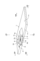
- FIG. 3 is a perspective view of a rear sheet metal of the display panel storage structure according to the embodiment.
- FIG. 4 is a partially enlarged perspective view of the outer panel of the display panel storage structure according to the embodiment.
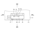
- FIG. 5 is a partial enlarged rear view of the outer panel of the display panel storage structure according to the embodiment.
- FIG. 6 is a partially enlarged plan view of the outer panel of the display panel housing structure according to the embodiment.
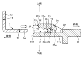
- FIG. 7 is a partially enlarged cross-sectional view of the display panel housing structure according to the embodiment.
- FIG. 8 is a partially enlarged cross-sectional view of the display panel housing structure according to the embodiment.
- FIG. 9 is a partially enlarged cross-sectional view of the display panel housing structure according to the embodiment.
- FIG. 10 is a partially enlarged cross-sectional view of the display panel housing structure according to the embodiment.
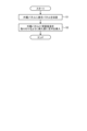
- FIG. 11 is a flowchart showing a display panel storage method according to the embodiment.
- the electronic device is, for example, an AV (Audio Visual) integrated car navigation device that is installed inside a vehicle.
- AV Audio Visual
- the front is the side seen by the operator, and corresponds to the front side of the electronic device shown in each figure.
- the side facing the rear of the vehicle is the front side (front).
- the top, bottom, right side, and left side are defined as viewed from the front, and the side opposite the front side is the rear side (rear side).
- the electronic device of the embodiment has a display unit 10.
- the electronic device has a device housing on the rear side of the display unit 10 that houses a control board that controls the display unit 10. Therefore, the display unit 10 is electrically connected to the device housing and attached to the device housing.
- the display unit 10 constitutes the display panel storage structure of the embodiment, and includes an exterior panel 11, a display panel 12, and a rear metal plate 13, as shown in FIG. 2.
- the display panel 12 includes, for example, a liquid crystal display (LCD) or an organic electroluminescence (EL) display.
- the display panel 12 is formed in the shape of a rectangular plate.
- the exterior panel 11 and rear metal plate 13 house the display panel 12 between them.
- the exterior panel 11 is made of synthetic resin material.
- the exterior panel 11 constitutes the exterior surrounding the front, upper, lower, right and left sides of the display panel 12.
- the exterior panel 11 has an opening 11F that opens in a rectangular shape at the rear, a front panel 11A on the front side, and upper peripheral wall 11B, lower peripheral wall 11C, right peripheral wall 11D and left peripheral wall 11E that surround the front panel 11A.
- the upper peripheral wall 11B, lower peripheral wall 11C, right peripheral wall 11D and left peripheral wall 11E are also simply referred to as peripheral walls.
- the upper peripheral wall 11B and lower peripheral wall 11C are provided on the relatively long side of the overall rectangular shape of the exterior panel 11, and the right peripheral wall 11D and left peripheral wall 11E are provided on the relatively short short side.
- the front panel 11A has an opening 11Aa that exposes the front of the display panel 12.
- the front surface of the display panel 12 that can be seen through the opening 11Aa is called the display surface 12A.
- the rear sheet metal 13 is made of a metal material.
- the rear sheet metal 13 is formed in a rectangular plate shape so as to close the opening 11F of the exterior panel 11.
- the rear sheet metal 13 has an upper periphery 13B, a lower periphery 13C, a right periphery 13D, and a left periphery 13E that are bent forward from the edge to surround the periphery.
- the upper periphery 13B, the lower periphery 13C, the right periphery 13D, and the left periphery 13E are also simply referred to as peripheries.
- the upper periphery 13B and the lower periphery 13C are provided on the relatively long side of the overall rectangular shape of the rear sheet metal 13, and the right periphery 13D and the left periphery 13E are provided on the relatively short short side.
- the upper periphery 13B, the lower periphery 13C, the right periphery 13D, and the left periphery 13E function as strength parts of the rear sheet metal 13 by bending.
- the rear sheet metal 13 also has through holes 13G.
- the through holes 13G are formed in a total of four locations near the right periphery 13D and the left periphery 13E.
- the through holes 13G are portions through which screws 14 pass, and the screws 14 are fastened into the screw holes 11G of the appearance panel 11 to fix the rear sheet metal 13 to the appearance panel 11.
- the display panel storage structure of the embodiment includes a tongue piece 1 provided on the rear metal plate 13 and an insertion portion 2 provided on the exterior panel 11.
- the tongue 1 is provided mainly on the upper and lower long sides of the rear sheet metal 13, which face each other vertically. In the embodiment, the tongue 1 is also provided on the right short side of the rear sheet metal 13.
- the tongue 1 is a plate-like piece that is bent forward at the center of each edge of the upper, lower, and right sides of the rear sheet metal 13 and extends forward along the peripheral walls 11B, 11C, and 11D of the appearance panel 11.
- the tongue 1 has a predetermined length in the front-to-back direction, a predetermined thickness in the top-to-bottom direction, and a predetermined width in the left-to-right direction on the upper and lower sides of the rear sheet metal 13.
- the tongue 1 has a predetermined length in the front-to-back direction, a predetermined thickness in the left-to-right direction, and a predetermined width in the top-to-bottom direction on the right side of the rear sheet metal 13.
- the tongue 1 has a pressing portion 1A, a restricting portion 1B, and an engagement recess 1C at the tip portion extending forward.
- the pressing portion 1A is the portion of the tongue 1 that extends the furthest forward and is the longest in the front-to-rear direction.
- the restricting portion 1B is a portion that is shorter than the pressing portion 1A on both sides of the width of the tongue 1.
- the engagement recess 1C is a portion of the tongue 1 on one side of the width of the pressing portion 1A that is cut out toward the rear and recessed toward the rear.
- the engagement recess 1C is arranged side by side with the pressing portion 1A in the width direction (a direction that intersects with the direction in which the tongue 1 is inserted into the insertion portion 2).
- the insertion portion 2 is a portion into which the tongue piece 1 is inserted (see Figures 7 to 10). As shown in Figure 2, the insertion portion 2 is provided mainly in the upper peripheral wall 11B and the lower peripheral wall 11C, which are the long side portions facing each other vertically, in the appearance panel 11. In the embodiment, the insertion portion 2 is also provided in the right side peripheral wall 11D, which is the short side portion, in the appearance panel 11. The insertion portion 2 is formed as a through hole penetrating in the front-rear direction at the center of each length of the upper peripheral wall 11B, the lower peripheral wall 11C, and the right side peripheral wall 11D of the appearance panel 11.
- the insertion portion 2 has a predetermined length in the front-rear direction, a predetermined gap in the top-bottom direction, and a predetermined width in the upper peripheral wall 11B and the lower peripheral wall 11C of the appearance panel 11. Also, the insertion portion 2 has a predetermined length in the front-rear direction, a predetermined gap in the top-bottom direction, and a predetermined width in the right side peripheral wall 11D of the appearance panel 11.
- Figures 4 to 10 show the insertion section 2 provided on the lower peripheral wall 11C, but the other peripheral walls 11B and 11D have the same configuration, so explanations will be omitted.
- the insertion section 2 is formed on the inner surface of the lower peripheral wall 11C, which is inside the opening 11F, in the exterior panel 11.
- the inner surface of the lower peripheral wall 11C is hollowed out from the rear end (back end) 11H towards the front, forming a through hole that penetrates in the front-to-rear direction with a notch 2D that thins the thickness of the lower peripheral wall 11C and a gate-shaped guide member 2E that surrounds the notch 2D in the width direction and penetrates through it in the front-to-rear direction (length direction), allowing the tongue piece 1 to be inserted from the rear side.
- the insertion portion 2 includes a vibration prevention portion 2A, a step portion 2B, and an engagement protrusion 2C.
- the vibration prevention part 2A is provided on the guide member 2E.
- the vibration prevention part 2A extends forward at the front end of the guide member 2E, and is provided between two slits 2Ea arranged in the width direction, and is formed so that it can elastically deform in a direction toward or away from the inner surface of the lower peripheral wall 11C due to the two slits 2Ea and its own elasticity.
- the vibration prevention part 2A is formed so that the tip 2Aa extending forward is bent toward the inner surface of the through hole of the insertion part 2 (here, the hollowed-out bottom surface of the notch 2D).
- the step portion 2B is formed inside the through hole formed by the notch 2D and the guide member 2E.
- the step portion 2B is formed protruding from the guide member 2E forming the through hole.
- the step portion 2B is also formed protruding from the notch 2D forming the through hole.
- the step portions 2B formed on the guide member 2E and the notch 2D are provided facing each other in the thickness direction.
- the opposing step portions 2B are provided at both ends in the width direction.
- the opposing step portions 2B are also formed with a slope 2Ba so that the distance between them increases toward the rear.
- the engagement protrusion 2C is the portion into which the engagement recess 1C of the tongue 1 inserted into the insertion portion 2 fits.
- the engagement protrusion 2C is formed inside the through hole formed by the notch 2D and the guide member 2E.
- the engagement protrusion 2C is formed with its tip facing toward the rear.
- the engagement protrusion 2C is aligned with the vibration prevention portion 2A in the width direction (a direction intersecting the direction in which the tongue 1 is inserted into the insertion portion 2).
- the insertion section 2 also has a recessed portion 2F formed by displacing the rear end 2Eb of the guide member 2E from the rear end 11H of the lower peripheral wall 11C in the insertion direction (front side) of the tongue 1, so that the rear end 2Eb of the guide member 2E is recessed.
- the above-mentioned insertion portion 2 is molded from a synthetic resin material together with the exterior panel 11.
- the mold for molding the insertion portion 2 includes a first slide mold that slides rearward mainly to form the through hole, step portion 2B, and engagement protrusion 2C formed by the notch 2D and guide member 2E, and a second slide mold that slides away from the inside of the peripheral wall mainly to form the vibration prevention portion 2A and the slit 2Ea. Therefore, the insertion portion 2 can be formed without using a special mold for its molding.
- the tongue 1 is formed with a constant plate thickness T1.
- the plate thickness T1 of the tongue 1 and the gap dimension T2 between the tip 2Aa of the vibration prevention portion 2A and the inner surface of the through hole of the insertion portion 2 are in a relationship in which the gap dimension T2 is smaller than the plate thickness T1.
- the plate thickness T1 of the tongue 1 and the gap dimension T3 between the opposing step portions 2B are in a relationship in which the gap dimension T3 is larger than the plate thickness T1.
- the plate thickness T4 of the back metal plate 13 having the tongue 1 and the offset dimension T5 of the recessed portion 2F are in a relationship in which the dimension T5 is larger than the plate thickness T4.
- the offset dimension T5 of the recessed portion 2F includes the thickness T4 of the rear metal plate 13.
- the display panel storage method for storing the display panel 12 using the display panel storage structure configured in this manner includes, as shown in Figures 2 and 5 to 11, a step (step S1) of housing the display panel 12 in the appearance panel 11, and a step (step S2) of inserting the tongue 1 into the insertion portion 2 so as to attach the rear metal plate 13 to the appearance panel 11. After inserting the tongue 1 into the insertion portion 2, the rear metal plate 13 is fixed to the appearance panel 11 with the screw 14.
- the tongue 1 is inserted into the through hole of the insertion section 2 so that the regulating portion 1B passes between the steps 2B while being guided by the inclined surface 2Ba of each of the opposing steps 2B in the relationship between the plate thickness T1 and the gap dimension T3.
- the pressing portion 1A abuts against the tip 2Aa of the vibration prevention portion 2A, pushing up the vibration prevention portion 2A and elastically deforming it in the relationship between the plate thickness T1 and the gap dimension T2.
- the vibration prevention portion 2A presses the pressing portion 1A against the inner surface of the through hole of the insertion section 2 (here, the hollowed-out bottom surface of the notch 2D) by its own elasticity so that the regulating portion 1B of the tongue 1 abuts against one of the opposing steps 2B.
- the tongue 1 inserted into the insertion section 2 has the engagement recess 1C fitted into the engagement protrusion 2C inside the through hole of the insertion section 2. This fit positions the rear sheet metal 13 on the appearance panel 11 via the tongue 1.
- the engagement recess 1C and engagement protrusion 2C that act in this way are called the positioning portion.
- the rear sheet metal 13 When the tongue 1 is inserted into the insertion portion 2, the rear sheet metal 13 is positioned forward of the rear end 11H of the lower peripheral wall 11C and enters the interior of the peripheral wall of the appearance panel 11, as the plate thickness T4 falls within the range of the dimension T5 of the recess 2F of the insertion portion 2.
- the engagement protrusion 2C that constitutes the positioning portion is provided toward the center in the width direction in the through hole formed by the notch 2D and the guide member 2E, as shown in Figures 9 and 10.
- the display panel storage structure of the embodiment includes an appearance panel 11 that houses a display panel 12, a rear metal sheet 13 that is attached to the appearance panel 11 so as to cover the rear surface of the display panel 12, a tongue 1 that is provided on the rear metal sheet 13 and extends along the peripheral walls 11B, 11C of the appearance panel 11, an insertion section 2 that is formed in the center of the peripheral walls 11B, 11C of the long side portion of the appearance panel 11 and into which the tongue 1 is inserted, and a vibration prevention section 2A that is provided on the insertion section 2, the vibration prevention section 2A being provided in a manner that presses the tongue 1 against the inner surface of the insertion section 2 by elastic deformation, a tip 2Aa that extends along the insertion direction of the tongue 1 is formed to face the inner surface, and the distance dimension T2 between the tip 2Aa and the inner surface is formed to be smaller than the plate thickness T1 of the tongue 1.
- the tongue 1 is pressed against the inner surface of the insertion portion 2 by the elastic deformation of the vibration prevention portion 2A, so that the rear sheet metal 13 having the tongue 1 is pressed against the appearance panel 11 with an elastic force.
- the display panel storage structure of the embodiment can suppress deformation of the peripheral walls 11B, 11C at the center of the long side of the appearance panel 11 by inserting the tongue 1 into the insertion portion 2.
- the display panel storage structure of the embodiment can prevent the generation of abnormal noise due to vibration because the tongue 1 is pressed against the inner surface of the insertion portion 2 by the elastic deformation of the vibration prevention portion 2A.
- the insertion portion 2 is formed in the center of the peripheral walls 11B, 11C of the long side of the appearance panel 11, where the amplitude of vibration is large, so that the effect of preventing the generation of vibration is large.
- the display panel storage structure of the embodiment can reduce the number of screws for fixing the rear sheet metal 13 to the appearance panel 11 by inserting the tongue 1 into the insertion portion 2, so that the manufacturing cost for the number of parts and the assembly man-hours can be reduced.
- the tongue 1 is formed with a constant plate thickness T1, and the vibration prevention part 2A holds down the tongue 1 by elastic deformation.
- the tongue 1 is provided with irregularities to hook the vibration prevention part 2A, the tongue 1 will be difficult to remove from the insertion part 2, and it will be difficult to remove the rear sheet metal 13 from the appearance panel 11 after assembly.
- the display panel storage structure of the embodiment does not have such problems and can prevent abnormal noise caused by vibration.
- the display panel storage structure of the embodiment further includes a positioning portion (engagement recess 1C, engagement protrusion 2C) that positions the rear metal sheet 13 inside the insertion portion 2 via the tongue piece 1 inserted into the insertion portion 2.
- this positioning portion (engagement protrusion 2C) is provided near the center in the width direction in the through hole formed by the notch 2D and the guide member 2E. Therefore, the dimensional tolerance for positioning the rear metal sheet 13 can be taken into account from the center of the long side across the width direction, improving positioning accuracy compared to when it is considered from the end of the long side across the width direction.
- the insertion portion 2 has a notch 2D formed by carving out the thickness of the peripheral walls 11B, 11C of the appearance panel 11, a guide member 2E that surrounds the notch 2D and enables the tongue 1 to be inserted, and a recessed portion 2F in which the guide member 2E is offset in position from the rear end 11H of the peripheral walls 11B, 11C in the direction of insertion of the tongue 1, including the plate thickness T4 of the rear metal sheet 13.
- the insertion portion 2 has a notch 2D formed by carving out the thickness of the peripheral walls 11B, 11C of the appearance panel 11, and a guide member 2E that surrounds the notch 2D and allows the tongue 1 to be inserted, so that the tongue 1 can be inserted so that it slips into part of the thickness of the peripheral walls 11B, 11C of the appearance panel 11, making it possible to reduce the height dimension of the display unit 10 and increase the accommodating height dimension of the display panel 12 compared to when notch 2D is not provided.
- the display panel storage structure of the embodiment can increase the volume that accommodates the display panel 12 and reduce the size of the members that are accommodated relative to the display panel 12.
- the guide member 2E has a recess 2F that is offset from the rear end 11H of the peripheral walls 11B, 11C in the insertion direction of the tongue 1 by including the thickness T4 of the back metal plate 13, so that the back metal plate 13 can be inserted into the recess 2F to assemble it to the appearance panel 11, and since the back metal plate 13 is positioned forward of the rear ends 11H of the peripheral walls 11B, 11C, the deformation of the peripheral walls 11B, 11C can be suppressed by the back metal plate 13, and the generation of abnormal noise due to vibration can be further prevented. Also, since the back metal plate 13 is positioned forward of the rear ends 11H of the peripheral walls 11B, 11C, the thickness dimension of the display unit 10 can be reduced.
- the electronic device of the embodiment also employs the display panel storage structure described above.
- This electronic device can reduce manufacturing costs while preventing abnormal noise caused by vibrations.
- the display panel storage method of the embodiment also includes the steps of applying the display panel storage structure described above to accommodate the display panel 12 in the exterior panel 11, and inserting the tongue piece 1 into the insertion portion 2 so as to attach the rear metal plate 13 to the exterior panel 11.
- This display panel storage method reduces manufacturing costs while preventing abnormal noise caused by vibration.
- This disclosure can reduce manufacturing costs while preventing abnormal noise caused by vibration.
Landscapes
- Physics & Mathematics (AREA)
- Engineering & Computer Science (AREA)
- General Physics & Mathematics (AREA)
- General Engineering & Computer Science (AREA)
- Nonlinear Science (AREA)
- Microelectronics & Electronic Packaging (AREA)
- Optics & Photonics (AREA)
- Crystallography & Structural Chemistry (AREA)
- Chemical & Material Sciences (AREA)
- Theoretical Computer Science (AREA)
- Mathematical Physics (AREA)
- Mechanical Engineering (AREA)
- Casings For Electric Apparatus (AREA)
- Devices For Indicating Variable Information By Combining Individual Elements (AREA)
- Liquid Crystal (AREA)
- Connection Of Plates (AREA)
Abstract
製造コストを低減しつつ、振動による異音の発生を防ぐこと。表示パネル格納構造は、表示パネルを収容する外観パネル(11)と、表示パネルの背面を覆うように外観パネル(11)に取り付けられる背面板金(13)と、背面板金(13)に設けられて外観パネル(11)の周壁(11C)に沿うように延びる舌片(1)と、外観パネル(11)の長辺部中央の周壁(11C)に形成されて舌片(1)が挿入される挿入部(2)と、挿入部(2)に設けられる振動防止部(2A)と、を含み、振動防止部(2A)は、弾性変形することにより舌片(1)を挿入部(2)の内面に向けて押さえ付ける態様で設けられており、舌片(1)の挿入方向に沿って延びる先端(2Aa)が内面に向いて形成され、先端(2Aa)と内面との間隔(T2)が舌片(1)の板厚(T1)よりも小さく形成される。
Description
本発明は、表示パネル格納構造、電子機器、並びに表示パネル格納方法に関する。
例えば、特許文献1には、ボディを構成するボディ本体と上部カバーとを組み付ける構造が示されている。この構造は、上部カバーの両側壁に係合片が設けられ、ボディ本体の両側壁に被係合部が設けられ、係合片を被係合部に嵌合させるものである。
ところで、例えば、電子機器は、表示部において、外観パネルに板金を固定して外観パネルと板金との間に液晶パネルのような表示パネルを格納する表示パネル格納構造が採用される。外観パネルは、液晶パネルを収容するように背面が開放された枠状に形成される。板金は、液晶パネルの背面側を覆うように形成され、その周縁に外観パネルの側壁の内面に沿うように折れ曲がった固定片が形成され、当該固定片が外側からネジで外観パネルに固定される。しかし、この表示パネル格納構造では、外側の複数方向からネジを固定するため、ネジの部品費用や組み立て工数が多く製造コストが嵩む問題がある。
そこで、表示パネル格納構造において、ネジで固定する点数を極力減らすには、特許文献1に示されるように、外観パネルの両側壁に被係合部を設け、板金に係合片を設ける嵌合構造が考えられる。しかしながら、この嵌合構造を採用した場合、係合片の厚みと被係合部の間隔との寸法公差の関係上、隙間が生じてしまう。そして、嵌合のみの構造により外観パネルの両側壁の剛性が低下して変形しやすく、この変形により、嵌合部分付近が振動で揺れ、隙間によって振動時に異音が発生する懸念がある。
本開示は、製造コストを低減しつつ、振動による異音の発生を防ぐことのできる表示パネル格納構造、電子機器、並びに表示パネル格納方法を提供することを目的とする。
上記の目的を達成するため、本開示の一態様の表示パネル格納構造は、表示パネルを収容する外観パネルと、前記表示パネルの背面を覆うように前記外観パネルに取り付けられる背面板金と、前記背面板金に設けられて前記外観パネルの周壁に沿うように延びる舌片と、前記外観パネルの長辺部の前記周壁の中央に形成されて前記舌片が挿入される挿入部と、前記挿入部に設けられる振動防止部と、を含み、前記振動防止部は、弾性変形することにより前記舌片を前記挿入部の内面に向けて押さえ付ける態様で設けられており、前記舌片の挿入方向に沿って延びる先端が前記内面に向いて形成され、前記先端と前記内面との間隔が前記舌片の板厚よりも小さく形成される。
上記の目的を達成するため、本開示の一態様の電子機器は、上述した表示パネル格納構造が適用される。
上記の目的を達成するため、本開示の一態様の表示パネル格納方法は、上述した表示パネル格納構造が適用し、前記外観パネルに前記表示パネルを収容する工程と、前記外観パネルに前記背面板金を取り付けるように、前記挿入部に前記舌片を挿入する工程と、を含む。
本開示によれば、製造コストを低減しつつ、振動による異音の発生を防ぐことができる。
以下、本開示を実施するための形態(以下、実施形態という)につき図面を参照しつつ詳細に説明する。なお、下記の実施形態により本開示が限定されるものではない。また、下記実施形態における構成要素には、当業者が容易に想定できるもの、実質的に同一のもの、いわゆる均等の範囲のものが含まれる。さらに、下記実施形態で開示した構成要素は適宜組み合わせることが可能である。
本実施形態に係る電子機器は、車両の内部に搭載される、例えば、AV(Audio Visual)一体型のカーナビゲーション装置である。
ここで、以下の説明において、正面とは、オペレータが視る面であって、各図で示す電子機器の前側に相当する。カーナビゲーション装置の場合は、車内前方に配置されるため、車内の後方に向く側が前側(正面)となる。また、本実施形態において、電子機器および表示パネル格納構造を説明するうえで、前側から視た状態を基準にして、上側、下側、右側、左側とし、前側の反対側を後側(背面)とする。
実施形態の電子機器は、図1に示すように、表示部10を有する。図には明示しないが、電子機器は、表示部10の後側に表示部10を制御する制御基板が収容される機器筐体を有する。従って、表示部10は、機器筐体に電気的に接続され、機器筐体に取り付けられる。
表示部10は、実施形態の表示パネル格納構造をなすものであり、図2に示すように、外観パネル11と、表示パネル12と、背面板金13と、を含む。
表示パネル12は、例えば、液晶ディスプレイ(LCD:Liquid Crystal Display)または有機EL(Electro-Luminescence)ディスプレイが含まれる。表示パネル12は、矩形の板状に形成される。
外観パネル11および背面板金13は、その間に表示パネル12を格納する。
外観パネル11は、合成樹脂材からなる。外観パネル11は、表示パネル12において、前側、上側、下側、右側、左側を囲む外観を構成する。外観パネル11は、後側が矩形状に開放する開放部11Fと、前側の正面板11Aと、正面板11Aの周りを囲む上側周壁11B、下側周壁11C、右側周壁11D、および左側周壁11Eと、を有する。上側周壁11B、下側周壁11C、右側周壁11D、および左側周壁11Eは、単に周壁ともいう。上側周壁11Bおよび下側周壁11Cは、外観パネル11の矩形状の全体形状において比較的長い長辺部に設けられ、右側周壁11Dおよび左側周壁11Eは、比較的短い短辺部に設けられる。正面板11Aは、表示パネル12の正面を露わにする開口11Aaが形成される。当該開口11Aaから視られる表示パネル12の正面を表示面12Aという。
背面板金13は、金属材からなる。背面板金13は、外観パネル11の開放部11Fを塞ぐように矩形の板状に形成される。背面板金13は、その周りを囲むように縁から前側に折り曲げられた上側周縁13B、下側周縁13C、右側周縁13D、および左側周縁13Eを有する。上側周縁13B、下側周縁13C、右側周縁13D、および左側周縁13Eは、単に周縁ともいう。上側周縁13Bおよび下側周縁13Cは、背面板金13の矩形状の全体形状において比較的長い長辺部に設けられ、右側周縁13Dおよび左側周縁13Eは、比較的短い短辺部に設けられる。上側周縁13B、下側周縁13C、右側周縁13D、および左側周縁13Eは、折り曲げ加工によって背面板金13の強度部分として機能する。また、背面板金13は、貫通孔13Gを有する。貫通孔13Gは、右側周縁13Dおよび左側周縁13Eの近傍の計4箇所に形成される。貫通孔13Gは、ネジ14が貫通する部分であり、このネジ14が外観パネル11のネジ穴11Gに締め付けられて背面板金13が外観パネル11に固定される。
実施形態の表示パネル格納構造は、背面板金13に設けられる舌片1と、外観パネル11に設けられる挿入部2と、を含む。
舌片1は、図2および図3に示すように、背面板金13において、主に、上下で対向する上側および下側の長辺部に設けられる。実施形態では、舌片1は、背面板金13において、右側の短辺部にも設けられる。舌片1は、背面板金13の上側、下側、右側のそれぞれの縁の中央において、前側に折り曲げられて前側に向けて外観パネル11の周壁11B,11C,11Dに沿うように延びて設けられた板片状のものである。舌片1は、背面板金13の上側および下側において、前後に所定の長さを有し、上下に所定の板厚を有し、左右に所定の幅を有する。また、舌片1は、背面板金13の右側において、前後に所定の長さを有し、左右に所定の板厚を有し、上下に所定の幅を有する。
舌片1は、図3に示すように、前側に延びる先端部において、押付部1Aと、規制部1Bと、係合凹部1Cと、を有する。押付部1Aは、舌片1において前側に最も延びて前後方向に最も長い部分である。規制部1Bは、舌片1の幅方向の両側において、押付部1Aよりも長さの短い部分である。係合凹部1Cは、押付部1Aの幅方向の一側において、舌片1が後側に切り欠かれて後側に凹んだ部分である。係合凹部1Cは、押付部1Aと幅方向(舌片1が挿入部2に挿入される方向に対して交差する方向)に並んで配置される。
挿入部2は、舌片1が挿入される部分である(図7から図10参照)。挿入部2は、図2に示すように、外観パネル11において、主に、上下で対向する長辺部である上側周壁11Bおよび下側周壁11Cに設けられる。実施形態では、挿入部2は、外観パネル11において、短辺部である右側周壁11Dにも設けられる。挿入部2は、外観パネル11の上側周壁11B、下側周壁11C、および右側周壁11Dのそれぞれの長さの中央において、前後方向に貫通する貫通孔として形成される。挿入部2は、外観パネル11の上側周壁11Bおよび下側周壁11Cにおいて、前後に所定の長さを有し、上下に所定の間隙を有し、左右に所定の幅を有する。また、挿入部2は、外観パネル11の右側周壁11Dにおいて、前後に所定の長さを有し、左右に所定の間隙を有し、上下に所定の幅を有する。なお、図4から図10では、説明の便宜上、下側周壁11Cに設けられた挿入部2を示しているが、他の周壁11B,11Dに設けられているものも同じ構成であるため、説明を省略する。
挿入部2は、外観パネル11において、開放部11Fの内側である下側周壁11Cの内面側に形成される。挿入部2は、下側周壁11Cの内面が後端(背面端)11Hから前側に向けて厚さがえぐられ、下側周壁11Cの厚さを薄く形成する切込2Dと、切込2Dを幅方向で囲んで前後方向(長さ方向)で突き抜ける門型のガイド部材2Eとで、前後方向に貫通する貫通孔を構成し、舌片1が後側から挿入可能に形成される。
挿入部2は、振動防止部2Aと、段部2Bと、係合突起2Cと、を含む。
振動防止部2Aは、ガイド部材2Eに設けられる。振動防止部2Aは、ガイド部材2Eの前側の端部において、前方に沿って延びて、幅方向に2つ配置されたスリット2Eaの間に設けられて、2つのスリット2Eaと、自身の弾性によって下側周壁11Cの内面に対して近づいたり離れたりする方向に弾性変形が可能に形成される。振動防止部2Aは、図7および図8に示すように、前方に延びる先端2Aaが、挿入部2の貫通孔の内面(ここでは、切込2Dのえぐられた底面)に向いて折れ曲がって形成される。
段部2Bは、図5、図7および図9に示すように、切込2Dとガイド部材2Eとがなす貫通孔の内部に形成される。段部2Bは、貫通孔をなすガイド部材2Eから突出して形成される。また、段部2Bは、貫通孔をなす切込2Dから突出して形成される。また、段部2Bは、ガイド部材2Eと切込2Dとに形成されたもの同士が厚さ方向で対向して設けられる。対向する各段部2Bは、幅方向の両端にそれぞれ設けられる。また、対向する各段部2Bは、後側に向けて相互の間隔が広がるように斜面2Baが形成される。
係合突起2Cは、図10に示すように、挿入部2に挿入された舌片1の係合凹部1Cが嵌る部分である。係合突起2Cは、切込2Dとガイド部材2Eとがなす貫通孔の内部に形成される。係合突起2Cは、先端を後側に向けて形成される。係合突起2Cは、振動防止部2Aと幅方向(舌片1が挿入部2に挿入される方向に対して交差する方向)に並んで配置される。
また、挿入部2は、ガイド部材2Eの後端2Ebが、下側周壁11Cの後端11Hから舌片1の挿入方向(前側)に位置がずれて配置されてガイド部材2Eの後端2Ebがえぐれたように形成されたえぐれ部2Fを有する。
上述した挿入部2は、外観パネル11と共に合成樹脂材で成形される。挿入部2を成形する金型は、図には明示しないが、主に切込2Dとガイド部材2Eとがなす貫通孔や段部2Bや係合突起2Cを形成するように後側にスライドする第一スライド金型と、主に振動防止部2Aおよびスリット2Eaを形成するように周壁の内側に離れるようにスライドする第二スライド金型と、を含む。従って、挿入部2は、その成形に特別な金型を用いることなく形成できる。
ここで、舌片1と挿入部2との各寸法の関係について図7を参照して説明する。舌片1は、一定の板厚T1で形成される。この舌片1の板厚T1と、舌片1の挿入前(振動防止部2Aが弾性変形する前)での振動防止部2Aの先端2Aaと挿入部2の貫通孔の内面(ここでは、振動防止部2Aの先端2Aaが向く側にある段部2Bの面)との隙間寸法T2とは、板厚T1よりも隙間寸法T2が小さい関係にある。また、舌片1の板厚T1と、対向する各段部2Bの間の隙間寸法T3とは、板厚T1よりも隙間寸法T3が大きい関係にある。また、舌片1を有する背面板金13の板厚T4と、えぐれ部2Fのずれた寸法T5(ガイド部材2Eの後端2Ebと下側周壁11Cの後端11Hとの前後にずれた寸法)とは、板厚T4よりも寸法T5が大きい関係にある。つまり、えぐれ部2Fのずれた寸法T5は、背面板金13の板厚T4分を含む。
このように構成された表示パネル格納構造を用いて、表示パネル12を格納する表示パネル格納方法は、図2、図5から図11に示すように、外観パネル11に表示パネル12を収容する工程(ステップS1)と、外観パネル11に背面板金13を取り付けるように、挿入部2に舌片1を挿入する工程(ステップS2)と、を含む。挿入部2に舌片1を挿入した後は、ネジ14によって外観パネル11に背面板金13を固定する。
舌片1は、図7および図8に示すように、板厚T1と隙間寸法T3との関係において、規制部1Bが、対向する各段部2Bの斜面2Baに案内されながら各段部2Bの間を通るように挿入部2の貫通孔に挿入される。挿入部2に挿入された舌片1は、板厚T1と隙間寸法T2との関係において、押付部1Aが、振動防止部2Aの先端2Aaに当接して振動防止部2Aを押し上げて弾性変形させる。この変形により、振動防止部2Aは、自身の弾性によって、舌片1の規制部1Bを対向する段部2Bの一方に当接させるように、挿入部2の貫通孔の内面(ここでは、切込2Dのえぐられた底面)に向けて押付部1Aを押さえ付ける。また、挿入部2に挿入された舌片1は、図9および図10に示すように、挿入部2の貫通孔の内部において、係合突起2Cに係合凹部1Cが嵌合する。この嵌合により、背面板金13は、舌片1を介して外観パネル11に位置決めされる。このように作用する係合凹部1Cおよび係合突起2Cを位置決め部という。そして、舌片1が挿入部2に挿入された背面板金13は、挿入部2のえぐれ部2Fの寸法T5の範囲内に板厚T4が入ることで、下側周壁11Cの後端11Hよりも前側に位置し、外観パネル11の周壁の内部に入り込む。なお、位置決め部を構成する係合突起2Cは、図9および図10に示すように、切込2Dとガイド部材2Eとがなす貫通孔において幅方向の中央寄りに設けられる。
このように、実施形態の表示パネル格納構造は、表示パネル12を収容する外観パネル11と、表示パネル12の背面を覆うように外観パネル11に取り付けられる背面板金13と、背面板金13に設けられて外観パネル11の周壁11B,11Cに沿うように延びる舌片1と、外観パネル11の長辺部の周壁11B,11Cの中央に形成されて舌片1が挿入される挿入部2と、挿入部2に設けられる振動防止部2Aと、を含み、振動防止部2Aは、弾性変形することにより舌片1を挿入部2の内面に向けて押さえ付ける態様で設けられており、舌片1の挿入方向に沿って延びる先端2Aaが内面に向いて形成され、先端2Aaと内面との間隔寸法T2が舌片1の板厚T1よりも小さく形成される。
この表示パネル格納構造によれば、振動防止部2Aの弾性変形によって舌片1を挿入部2の内面に向けて押さえ付けるようにしたことにより、舌片1を有する背面板金13が外観パネル11に対して弾性力を伴って押さえつけられる。この結果、実施形態の表示パネル格納構造は、挿入部2への舌片1の挿入によって外観パネル11の長辺部中央の周壁11B,11Cの変形を抑制できる。また、実施形態の表示パネル格納構造は、振動防止部2Aの弾性変形によって舌片1を挿入部2の内面に向けて押さえ付けるため、振動による異音の発生を防ぐことができる。特に、この表示パネル格納構造によれば、挿入部2が、振動の振幅が大きくなる外観パネル11の長辺部の周壁11B,11Cの中央に形成されているため、振動の発生の防止効果が大きい。これにより、実施形態の表示パネル格納構造は、挿入部2への舌片1の挿入によって背面板金13を外観パネル11に固定するネジの点数を削減できるため、部品点数や組み立て工数にかかる製造コストを低減できる。なお、舌片1は、一定の板厚T1で形成されており、振動防止部2Aは、この舌片1を弾性変形によって押さえ付ける。舌片1に凹凸を設けて振動防止部2Aを引っかける構成では、舌片1が挿入部2から抜け難くなり、組み付け後に背面板金13を外観パネル11から外すことが難しくなる。実施形態の表示パネル格納構造は、このような問題が無く、かつ振動による異音の発生を防ぐことができる。
また、実施形態の表示パネル格納構造では、挿入部2の内部において、挿入部2に挿入された舌片1を介して背面板金13の位置決めをする位置決め部(係合凹部1C、係合突起2C)をさらに含む。
この表示パネル格納構造によれば、位置決め部によって背面板金13の位置決めをすることで、外観パネル11と背面板金13との組み付け位置のずれを抑えることができる。この位置決め部(係合突起2C)は、図9および図10に示すように、切込2Dとガイド部材2Eとがなす貫通孔において幅方向の中央寄りに設けられる。従って、背面板金13の位置決めの寸法公差を長辺部の中央から幅方向に亘って考慮できるため、長辺部の端部から幅方向に亘って考慮する場合と比べて位置決め精度を向上できる。
また、実施形態の表示パネル格納構造では、挿入部2は、外観パネル11の周壁11B,11Cの厚さをえぐって形成された切込2Dと、切込2Dを囲んで舌片1を挿入可能にするガイド部材2Eと、ガイド部材2Eが周壁11B,11Cの後端11Hから背面板金13の板厚T4分を含み舌片1の挿入方向に位置がずれたえぐれ部2Fと、を有する。
この表示パネル格納構造によれば、挿入部2が、外観パネル11の周壁11B,11Cの厚さをえぐって形成された切込2Dと、切込2Dを囲んで舌片1を挿入可能にするガイド部材2Eと、を有することで、外観パネル11の周壁11B,11Cの厚さの一部に潜り込むように舌片1を挿入でき、切込2Dを設けない場合と比較して表示部10の高さ寸法を抑え、且つ表示パネル12の収容可能な高さ寸法を拡げることができる。この結果、実施形態の表示パネル格納構造は、表示パネル12を収容する容積を大きくしたり、表示パネル12に対して収容する部材の大きさを小さくしたりすることができる。しかも、この表示パネル格納構造によれば、ガイド部材2Eが周壁11B,11Cの後端11Hから背面板金13の板厚T4分を含み舌片1の挿入方向に位置がずれたえぐれ部2Fを有することで、背面板金13の板厚T4分をえぐれ部2Fに差し込んで外観パネル11に組み付けることができ、周壁11B,11Cの後端11Hよりも前側に背面板金13を配置するため、周壁11B,11Cの変形を背面板金13によって抑制でき、振動による異音の発生をより防ぐことができる。また、周壁11B,11Cの後端11Hよりも前側に背面板金13を配置するため、表示部10の厚さ寸法を抑えることができる。
また、実施形態の電子機器は、上述した表示パネル格納構造が適用される。
この電子機器によれば、製造コストを低減しつつ、振動による異音の発生を防ぐことができる。
また、実施形態の表示パネル格納方法は、上述した表示パネル格納構造を適用し、外観パネル11に表示パネル12を収容する工程と、外観パネル11に背面板金13を取り付けるように、挿入部2に舌片1を挿入する工程と、を含む。
この表示パネル格納方法によれば、製造コストを低減しつつ、振動による異音の発生を防ぐことができる。
本開示は、製造コストを低減しつつ、振動による異音の発生を防ぐことができる。
1 舌片
1C 係合凹部(位置決め部)
2 挿入部
2A 振動防止部
2Aa 先端
2C 係合突起(位置決め部)
2D 切込
2E ガイド部材
2F えぐれ部
11 外観パネル
11H 後端(背面端)
11B,11C 周壁
12 表示パネル
13 背面板金
1C 係合凹部(位置決め部)
2 挿入部
2A 振動防止部
2Aa 先端
2C 係合突起(位置決め部)
2D 切込
2E ガイド部材
2F えぐれ部
11 外観パネル
11H 後端(背面端)
11B,11C 周壁
12 表示パネル
13 背面板金
Claims (5)
- 表示パネルを収容する外観パネルと、
前記表示パネルの背面を覆うように前記外観パネルに取り付けられる背面板金と、
前記背面板金に設けられて前記外観パネルの周壁に沿うように延びる舌片と、
前記外観パネルの長辺部の前記周壁の中央に形成されて前記舌片が挿入される挿入部と、
前記挿入部に設けられる振動防止部と、
を含み、
前記振動防止部は、弾性変形することにより前記舌片を前記挿入部の内面に向けて押さえ付ける態様で設けられており、前記舌片の挿入方向に沿って延びる先端が前記内面に向いて形成され、前記先端と前記内面との間隔が前記舌片の板厚よりも小さく形成される、
表示パネル格納構造。 - 前記挿入部の内部において、前記挿入部に挿入された前記舌片を介して前記背面板金の位置決めをする位置決め部をさらに含む、請求項1に記載の表示パネル格納構造。
- 前記挿入部は、
前記外観パネルの前記周壁の厚さをえぐって形成された切込と、
当該切込を囲んで前記舌片を挿入可能にするガイド部材と、
前記ガイド部材が前記周壁の背面端から前記背面板金の板厚分を含み前記舌片の挿入方向に位置がずれたえぐれ部と、
を有する、請求項1または2に記載の表示パネル格納構造。 - 表示パネルを収容する外観パネルと、
前記表示パネルの背面を覆うように前記外観パネルに取り付けられる背面板金と、
前記背面板金に設けられて前記外観パネルの周壁に沿うように延びる舌片と、
前記外観パネルの長辺部の前記周壁の中央に形成されて前記舌片が挿入される挿入部と、
前記挿入部に設けられる振動防止部と、
を含み、
前記振動防止部は、弾性変形することにより前記舌片を前記挿入部の内面に向けて押さえ付ける態様で設けられており、前記舌片の挿入方向に沿って延びる先端が前記内面に向いて形成され、前記先端と前記内面との間隔が前記舌片の板厚よりも小さく形成される、表示パネル格納構造が適用される、電子機器。 - 表示パネルを収容する外観パネルと、
前記表示パネルの背面を覆うように前記外観パネルに取り付けられる背面板金と、
前記背面板金に設けられて前記外観パネルの周壁に沿うように延びる舌片と、
前記外観パネルの長辺部の前記周壁の中央に形成されて前記舌片が挿入される挿入部と、
前記挿入部に設けられる振動防止部と、
を含み、
前記振動防止部は、弾性変形することにより前記舌片を前記挿入部の内面に向けて押さえ付ける態様で設けられており、前記舌片の挿入方向に沿って延びる先端が前記内面に向いて形成され、前記先端と前記内面との間隔が前記舌片の板厚よりも小さく形成される、表示パネル格納構造を適用し、
前記外観パネルに前記表示パネルを収容する工程と、
前記外観パネルに前記背面板金を取り付けるように、前記挿入部に前記舌片を挿入する工程と、
を含む、表示パネル格納方法。
Applications Claiming Priority (2)
| Application Number | Priority Date | Filing Date | Title |
|---|---|---|---|
| JP2023088932A JP2024171749A (ja) | 2023-05-30 | 2023-05-30 | 表示パネル格納構造、電子機器、並びに表示パネル格納方法 |
| JP2023-088932 | 2023-05-30 |
Publications (1)
| Publication Number | Publication Date |
|---|---|
| WO2024247693A1 true WO2024247693A1 (ja) | 2024-12-05 |
Family
ID=93657660
Family Applications (1)
| Application Number | Title | Priority Date | Filing Date |
|---|---|---|---|
| PCT/JP2024/017634 Ceased WO2024247693A1 (ja) | 2023-05-30 | 2024-05-13 | 表示パネル格納構造、電子機器、並びに表示パネル格納方法 |
Country Status (2)
| Country | Link |
|---|---|
| JP (1) | JP2024171749A (ja) |
| WO (1) | WO2024247693A1 (ja) |
Citations (8)
| Publication number | Priority date | Publication date | Assignee | Title |
|---|---|---|---|---|
| JPS63261897A (ja) * | 1987-04-20 | 1988-10-28 | ソニー株式会社 | キヤビネツト装置 |
| JPH07249878A (ja) * | 1994-03-14 | 1995-09-26 | Alpine Electron Inc | 電子機器の化粧体固定装置 |
| JP2001305985A (ja) * | 2000-04-19 | 2001-11-02 | Nec Corp | 表示装置および情報端末機器 |
| KR20060057669A (ko) * | 2004-11-23 | 2006-05-26 | 엘지전자 주식회사 | 디스크 드라이브의 진동 및 변형 방지구조 |
| JP2006228964A (ja) * | 2005-02-17 | 2006-08-31 | Fujitsu Ten Ltd | 固定構造 |
| JP2008185764A (ja) * | 2007-01-30 | 2008-08-14 | Mitsubishi Electric Corp | シールドカバー取付け構造および表示装置 |
| US20100246121A1 (en) * | 2009-03-27 | 2010-09-30 | Hong Fu Jin Precision Industry (Shenzhen) Co., Ltd | Release module and computer housing using the same |
| JP2022138631A (ja) * | 2021-03-10 | 2022-09-26 | 新電元工業株式会社 | 電子装置 |
-
2023
- 2023-05-30 JP JP2023088932A patent/JP2024171749A/ja active Pending
-
2024
- 2024-05-13 WO PCT/JP2024/017634 patent/WO2024247693A1/ja not_active Ceased
Patent Citations (8)
| Publication number | Priority date | Publication date | Assignee | Title |
|---|---|---|---|---|
| JPS63261897A (ja) * | 1987-04-20 | 1988-10-28 | ソニー株式会社 | キヤビネツト装置 |
| JPH07249878A (ja) * | 1994-03-14 | 1995-09-26 | Alpine Electron Inc | 電子機器の化粧体固定装置 |
| JP2001305985A (ja) * | 2000-04-19 | 2001-11-02 | Nec Corp | 表示装置および情報端末機器 |
| KR20060057669A (ko) * | 2004-11-23 | 2006-05-26 | 엘지전자 주식회사 | 디스크 드라이브의 진동 및 변형 방지구조 |
| JP2006228964A (ja) * | 2005-02-17 | 2006-08-31 | Fujitsu Ten Ltd | 固定構造 |
| JP2008185764A (ja) * | 2007-01-30 | 2008-08-14 | Mitsubishi Electric Corp | シールドカバー取付け構造および表示装置 |
| US20100246121A1 (en) * | 2009-03-27 | 2010-09-30 | Hong Fu Jin Precision Industry (Shenzhen) Co., Ltd | Release module and computer housing using the same |
| JP2022138631A (ja) * | 2021-03-10 | 2022-09-26 | 新電元工業株式会社 | 電子装置 |
Also Published As
| Publication number | Publication date |
|---|---|
| JP2024171749A (ja) | 2024-12-12 |
Similar Documents
| Publication | Publication Date | Title |
|---|---|---|
| JP4379288B2 (ja) | 電子装置の筐体構造 | |
| JP6366413B2 (ja) | 電子回路ユニット | |
| JP5658491B2 (ja) | 電子機器収納ケース | |
| JP5194576B2 (ja) | ブラケット及びブラケットが取り付けられる車載用電子機器 | |
| WO2024247693A1 (ja) | 表示パネル格納構造、電子機器、並びに表示パネル格納方法 | |
| CN102356705B (zh) | 组装到面板的组装结构 | |
| JP4075971B2 (ja) | 電子制御式油圧パワーステアリングの制御器 | |
| JP2000188491A (ja) | 基板保持構造 | |
| JP7247486B2 (ja) | 筐体 | |
| JP2012009747A (ja) | 電子機器収納ケース | |
| JP6611366B2 (ja) | 電気接続箱 | |
| JP5113345B2 (ja) | 液晶表示装置 | |
| JP2024101096A (ja) | 電子制御部品用ブラケット | |
| JP5881867B2 (ja) | 電子機器 | |
| JP7224789B2 (ja) | 車両用電子制御装置 | |
| JP4723912B2 (ja) | シャーシの嵌合構造 | |
| JP4508162B2 (ja) | 回路基板の収納構造 | |
| JP4674801B2 (ja) | 電子機器における操作釦取付け構造 | |
| WO2024252852A1 (ja) | 表示パネル格納構造、電子機器、並びに表示パネル格納方法 | |
| WO2018198520A1 (ja) | ケース及び電子装置 | |
| JP2009296755A (ja) | 螺子体取付部の構造及び配線器具取付体 | |
| JP3212247B2 (ja) | 筐体構造 | |
| JP3928801B2 (ja) | トップカバーの取付構造 | |
| JP2023159584A (ja) | 電気接続箱 | |
| WO2024185275A1 (ja) | 装置本体取付構造 |
Legal Events
| Date | Code | Title | Description |
|---|---|---|---|
| 121 | Ep: the epo has been informed by wipo that ep was designated in this application |
Ref document number: 24815177 Country of ref document: EP Kind code of ref document: A1 |
|
| NENP | Non-entry into the national phase |
Ref country code: DE |