WO2024247477A1 - アタッチメント光学系 - Google Patents
アタッチメント光学系 Download PDFInfo
- Publication number
- WO2024247477A1 WO2024247477A1 PCT/JP2024/013697 JP2024013697W WO2024247477A1 WO 2024247477 A1 WO2024247477 A1 WO 2024247477A1 JP 2024013697 W JP2024013697 W JP 2024013697W WO 2024247477 A1 WO2024247477 A1 WO 2024247477A1
- Authority
- WO
- WIPO (PCT)
- Prior art keywords
- optical system
- lens
- attachment
- optical element
- objective lens
- Prior art date
- Legal status (The legal status is an assumption and is not a legal conclusion. Google has not performed a legal analysis and makes no representation as to the accuracy of the status listed.)
- Ceased
Links
Images











Classifications
-
- G—PHYSICS
- G02—OPTICS
- G02B—OPTICAL ELEMENTS, SYSTEMS OR APPARATUS
- G02B21/00—Microscopes
- G02B21/02—Objectives
- G02B21/025—Objectives with variable magnification
-
- G—PHYSICS
- G02—OPTICS
- G02B—OPTICAL ELEMENTS, SYSTEMS OR APPARATUS
- G02B21/00—Microscopes
-
- G—PHYSICS
- G02—OPTICS
- G02B—OPTICAL ELEMENTS, SYSTEMS OR APPARATUS
- G02B21/00—Microscopes
- G02B21/0004—Microscopes specially adapted for specific applications
- G02B21/002—Scanning microscopes
- G02B21/0024—Confocal scanning microscopes (CSOMs) or confocal "macroscopes"; Accessories which are not restricted to use with CSOMs, e.g. sample holders
- G02B21/0028—Confocal scanning microscopes (CSOMs) or confocal "macroscopes"; Accessories which are not restricted to use with CSOMs, e.g. sample holders specially adapted for specific applications, e.g. for endoscopes, ophthalmoscopes, attachments to conventional microscopes
-
- G—PHYSICS
- G02—OPTICS
- G02B—OPTICAL ELEMENTS, SYSTEMS OR APPARATUS
- G02B21/00—Microscopes
- G02B21/0004—Microscopes specially adapted for specific applications
- G02B21/002—Scanning microscopes
- G02B21/0024—Confocal scanning microscopes (CSOMs) or confocal "macroscopes"; Accessories which are not restricted to use with CSOMs, e.g. sample holders
- G02B21/0052—Optical details of the image generation
- G02B21/0076—Optical details of the image generation arrangements using fluorescence or luminescence
-
- G—PHYSICS
- G02—OPTICS
- G02B—OPTICAL ELEMENTS, SYSTEMS OR APPARATUS
- G02B21/00—Microscopes
- G02B21/02—Objectives
Definitions
- the present invention relates to an attachment optical system for a microscope.
- the attachment optical system according to the present invention is an attachment optical system for a microscope that is detachably mounted between an objective lens that receives light from an object and converts it into parallel light, and an imaging lens that forms an image from the light from the objective lens, and has a first optical element with negative refractive power and a second optical element with positive refractive power.
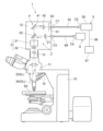
- FIG. 1 is a schematic diagram showing a confocal fluorescence microscope.
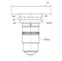
- FIG. 2 is a schematic diagram showing the vicinity of a revolver in a confocal fluorescence microscope.
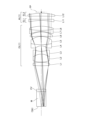
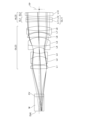
- FIG. 2 is a cross-sectional view showing the configuration of an attachment optical system and an objective lens in the first example.
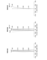
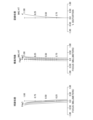
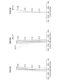
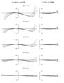
- 5A to 5C are diagrams showing various aberrations of the attachment optical system according to the first example when silicone is used as the immersion liquid.
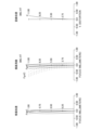
- 6A to 6C are diagrams showing various aberrations of the attachment optical system according to the first example when glycerin is used as the immersion liquid.
- 5A to 5C are diagrams showing various aberrations in the attachment optical system according to the first example when oil is used as the immersion liquid.
- 5A to 5C are diagrams showing various aberrations in the attachment optical system according to the first example when water is used as the immersion liquid.
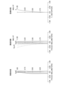
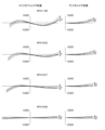
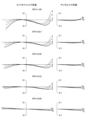
- 6A to 6C are diagrams illustrating coma aberration of the attachment optical system according to the first example when silicone is used as the immersion liquid.
- 6A to 6C are diagrams illustrating coma aberration of the attachment optical system according to the first example when glycerin is used as the immersion liquid.
- 6A to 6C are diagrams illustrating coma aberration of the attachment optical system according to the first example when oil is used as the immersion liquid.
- 6A to 6C are diagrams illustrating coma aberration of the attachment optical system according to the first example when water is used as the immersion liquid.
- FIG. 11 is a cross-sectional view showing the configuration of an attachment optical system and an objective lens in the second example.
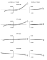
- 13A to 13C are diagrams showing various aberrations of the attachment optical system according to the second example when silicone is used as the immersion liquid.
- 13A to 13C are diagrams showing various aberrations of the attachment optical system according to the second example when glycerin is used as the immersion liquid.
- 13A to 13C are diagrams showing various aberrations in the attachment optical system according to the second example when oil is used as the immersion liquid.
- 13A to 13C are diagrams showing various aberrations in the attachment optical system according to the second example when water is used as the immersion liquid.
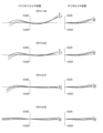
- 13A and 13B are diagrams illustrating coma aberration of the attachment optical system according to the second example when silicone is used as the immersion liquid.
- FIG. 13 is a cross-sectional view showing the configuration of an attachment optical system and an objective lens in the third example.
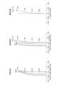
- 13A to 13C are diagrams showing various aberrations in the attachment optical system according to the third example when observing an object at a water depth of 0.5 mm.
- 13A to 13C are diagrams showing various aberrations in the attachment optical system according to the third example when observing an object at a depth of 2.5 mm underwater.
- 13A to 13C are diagrams showing various aberrations in the attachment optical system according to the third example when observing an object at a depth of 3.5 mm.
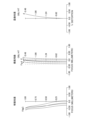
- 13A to 13C are diagrams illustrating coma aberration in the attachment optical system according to the third example when observing an object at a water depth of 0.5 mm.
- 13A to 13C are diagrams illustrating coma aberration in the attachment optical system according to the third example when observing an object at a depth of 2.5 mm.
- FIG. 13A to 13C are diagrams illustrating coma aberration in the attachment optical system according to the third example when observing an object at a depth of 3.5 mm.
- FIG. 13 is a cross-sectional view showing the configuration of an attachment optical system and an objective lens in the fourth example.
- 13A to 13C are diagrams showing various aberrations of the attachment optical system according to the fourth example when silicone is used as the immersion liquid.
- 13A to 13C are diagrams showing various aberrations of the attachment optical system according to the fourth example when glycerin is used as the immersion liquid.
- 13A to 13C are diagrams showing various aberrations in the attachment optical system according to the fourth example when oil is used as the immersion liquid.
- FIG. 2 is a cross-sectional view showing a configuration of an imaging lens.
- the confocal fluorescence microscope 1 is configured to include an excitation light introduction section 2 that directs illumination laser light from a light source unit 6 onto a sample SA, a scanning device 3 that deflects the laser light focused on the sample SA to scan it over the sample SA, a photodetector 5 that detects a light intensity signal from the sample SA, and a focusing optical system 4 that directs light from the sample SA to the photodetector 5.
- the light source unit 6 may be provided in the confocal fluorescence microscope 1, or may be provided separately from the confocal fluorescence microscope 1.
- the light source unit 6 is configured to include a laser light source (not shown) and a beam diameter adjustment mechanism (not shown). The light source unit 6 oscillates laser light for illumination.
- the excitation light introduction section 2 is composed of a collimator lens 21, a dichroic mirror 22, an imaging lens 23, and an objective lens 24.
- the collimator lens 21 and the dichroic mirror 22 are arranged inside the microscope housing section 12 provided on the upper part of the lens barrel section 11 in the microscope main body 10.
- the light source unit 6 and the microscope housing section 12 are connected by an optical fiber 69 using connectors C3 and C4.
- the collimator lens 21 converts the laser light (light beam) emitted from the light source unit 6 into parallel light.
- the dichroic mirror 22 reflects the laser light from the collimator lens 21 toward the sample SA.
- the laser light reflected by the dichroic mirror 22 is focused on the sample SA by the imaging lens 23 and the objective lens 24.
- the imaging lens 23 is arranged inside the lens barrel section 11 in the microscope main body 10.
- the imaging lens 23 is also called a second objective lens.
- the objective lens 24 is removably attached to the revolver 15 provided at the bottom of the lens barrel 11.
- the objective lens 24 can be detachably attached to the revolver 15 together with the attachment optical system 25.
- the attachment optical system 25 is detachably attached between the objective lens 24 and the imaging lens 23.
- the imaging lens 23, the attachment optical system 25, and the objective lens 24 focus the laser light reflected by the dichroic mirror 22 on the sample SA.
- the optical elements constituting the attachment optical system 25 are housed in a cylindrical optical element housing 26.
- a first screw portion 27a is formed on one end side (the objective lens 24 side) of the optical element housing 26, and a second screw portion 27b is formed on the other end side (the opposite side to the objective lens 24 side) of the optical element housing 26.
- the first screw portion 27a is a female screw that can be screwed into the screw portion (not shown) of the objective lens 24.
- the second screw portion 27b is a male screw that can be screwed into a screw portion (not shown) of the revolver 15.
- a correction collar 28 that is rotated to correct aberrations is provided on the side of the optical element housing 26.
- the scanning device 3 is configured with a scanning mechanism (scanner) 31 and a scanning optical system 32.
- the scanning device 3 is disposed between the dichroic mirror 22 and the imaging lens 23 inside the microscope housing 12.
- the scanning mechanism (scanner) 31 is configured with, for example, a galvanometer mirror (not shown) or a resonant mirror (not shown).
- the scanning mechanism (scanner) 31 deflects the incident laser light. In other words, the scanning mechanism (scanner) 31 deflects the laser light focused on the sample SA to scan the sample SA.
- the scanning optical system 32 is an optical system provided between the scanning mechanism (scanner) 31 and the imaging lens 23.
- the scanning optical system 32 is an optical system in which the focal position of the scanning optical system 32 is located on the imaging plane 13 (also called the primary image plane) that is conjugate with the sample SA (the scanning plane of the sample SA).
- the focusing optical system 4 is composed of an objective lens 24, an imaging lens 23, a total reflection mirror 41, and a condensing lens 42.
- the objective lens 24 receives the fluorescence generated by the sample SA and converts it into parallel light.
- the imaging lens 23 focuses the fluorescence (parallel light) emitted from the objective lens 24 on the imaging surface 13 (primary image surface) to form an image.
- the attachment optical system 25 is attached between the objective lens 24 and the imaging lens 23, the imaging lens 23 focuses the fluorescence from the objective lens 24 that has passed through the attachment optical system 25 on the imaging surface 13 to form an image.
- the fluorescence from the sample SA that has passed through the imaging lens 23 is focused on the imaging surface 13, passes through the scanning device 3 and the dichroic mirror 22, and reaches the total reflection mirror 41.
- the total reflection mirror 41 and the condensing lens 42 are arranged above the dichroic mirror 22 inside the microscope housing 12.
- the total reflection mirror 41 reflects the fluorescence from the sample SA that has passed through the imaging lens 23.
- the focusing lens 42 focuses the fluorescence reflected by the total reflection mirror 41 onto a light shielding plate 52 that has a pinhole 51 (aperture).
- the light detection device 5 is configured with a light shielding plate 52 having a pinhole 51, an optical fiber 53, and a detection unit 55.
- the optical fiber 53 is connected to the microscope housing 12 and the detection unit 55 using connectors C1 and C2.
- Light (fluorescence) that has passed through the pinhole 51 is incident on the optical fiber 53.
- the detection unit 55 detects the light (fluorescence) that has passed through the pinhole 51 and the optical fiber 53.
- a processing unit 57 is electrically connected to the detection unit 55 via a cable 56.
- the processing unit 57 performs image processing (of the sample SA) based on the detection signal detected by the detection unit 55, and the observation image of the sample SA obtained by the image processing of the processing unit 57 is displayed on a monitor (not shown).
- the laser light from the scanning device 3 is once focused on the image plane 13 (primary image plane) and then focused again on the sample SA by the imaging lens 23 and the objective lens 24.
- the attachment optical system 25 is attached between the objective lens 24 and the imaging lens 23
- the laser light from the scanning device 3 is once focused on the image plane 13 and then focused again on the sample SA by the imaging lens 23, the attachment optical system 25, and the objective lens 24. That is, the scanning surface of the sample SA, the imaging surface 13, and the pinhole 51 are in a conjugate relationship with each other. Therefore, by configuring the light (fluorescence) to be focused on the sample SA by the imaging lens 23 and (the attachment optical system 25) and the objective lens 24, it becomes possible to pass the fluorescence generated on the scanning surface of the sample SA through the pinhole 51.
- the confocal fluorescence microscope 1 has been described as an example of a microscope to which the attachment optical system according to this embodiment can be attached, the present invention is not limited to this.
- the microscope to which the attachment optical system according to this embodiment can be attached may be a multiphoton excitation microscope, a super-resolution microscope, an observation microscope, etc.
- the confocal fluorescence microscope 1 may be an upright microscope or an inverted microscope.
- attachment optical system 25 that can be attached between the objective lens 24 and the imaging lens 23 of such a confocal fluorescence microscope 1, it is possible to use the attachment optical system AL described below. Also, as the objective lens 24 and the imaging lens 23 of such a confocal fluorescence microscope 1, it is possible to use the objective lens OL and the imaging lens IL described below.
- the attachment optical system AL according to this embodiment will be described.
- the attachment optical system AL (1) shown in FIG. 3 has a first optical element EL1 having a negative refractive power and a second optical element EL2 having a positive refractive power.
- the attachment optical system AL according to this embodiment may be the attachment optical system AL(2) shown in FIG. 12, the attachment optical system AL(3) shown in FIG. 21, or the attachment optical system AL(4) shown in FIG. 28.
- At least one of the first optical element EL1 and the second optical element EL2 may be movable along the optical axis. This allows for excellent correction of axial chromatic aberration that occurs depending on the refractive index and Abbe number of the sample or immersion liquid.
- either one of the first optical element EL1 and the second optical element EL2 may be movable along the optical axis.
- the first optical element EL1 and the second optical element EL2 may each be movable along the optical axis.
- At least one of the first optical element EL1 and the second optical element EL2 may be movable in a direction perpendicular to the optical axis. This allows for good correction of aberrations due to decentering of the objective lens or the imaging lens (microscope).
- either one of the first optical element EL1 and the second optical element EL2 may be movable in a direction perpendicular to the optical axis.
- the first optical element EL1 and the second optical element EL2 may each be movable in a direction perpendicular to the optical axis.
- the attachment optical system AL may satisfy the following conditional expression (1). 2 ⁇
- fA focal length of the attachment optical system AL
- TLA total length of the attachment optical system AL
- Conditional formula (1) specifies the appropriate relationship between the focal length of the attachment optical system AL and the overall length of the attachment optical system AL.
- conditional formula (1) specifies the appropriate relationship between the focal length of the attachment optical system AL and the overall length of the attachment optical system AL.
- the overall magnification of the microscope does not change significantly even when the attachment optical system AL is attached, so that the fluctuation in the field of view range of the microscope due to the attachment optical system AL can be suppressed.
- the effect of this embodiment can be made more certain by setting the lower limit of conditional formula (1) to 25, or even 100.
- the effect of this embodiment can be made more certain by setting the upper limit of conditional formula (1) to 7000, 5000, 3000, or even 1500.
- a first optical element EL1 and a second optical element EL2 may be arranged in this order from the objective lens OL side along the optical axis. This causes the light rays passing through the attachment optical system AL to move away from the optical axis, allowing for good correction of spherical aberration. It is also possible to correct aberrations (axial chromatic aberration and spherical aberration) that occur depending on the type of sample or immersion liquid.
- the second optical element EL2 is one positive lens or one cemented lens having at least a positive lens, and may satisfy the following conditional expression (2). 35 ⁇ dP ⁇ 101...(2) where ⁇ dP is the Abbe number of the positive lens
- Conditional formula (2) specifies an appropriate range for the Abbe number of the positive lens. By satisfying conditional formula (2), axial chromatic aberration and spherical aberration can be corrected well.
- the effect of this embodiment can be made more certain by setting the lower limit of conditional formula (2) to 40, or even 45.
- the effect of this embodiment can be made more certain by setting the upper limit of conditional formula (2) to 96, 90, or even 80.
- the second optical element EL2 may be a single positive lens.
- the first optical element EL1 is one negative lens or one cemented lens having at least a negative lens
- the second optical element EL2 is one positive lens or one cemented lens having at least a positive lens, and may satisfy the following conditional expression (3). 0 ⁇ dP ⁇ dN ⁇ 30 (3) where ⁇ dP is the Abbe number of the positive lens, and ⁇ dN is the Abbe number of the negative lens.
- Conditional formula (3) specifies the appropriate relationship between the Abbe number of the positive lens and the Abbe number of the negative lens. By satisfying conditional formula (3), axial chromatic aberration can be corrected satisfactorily. If the corresponding value of conditional formula (3) is outside the above range, the difference in Abbe number between the positive lens and the negative lens becomes too large, so that the aberration correction by the attachment optical system AL becomes excessive, making it difficult to correct axial chromatic aberration satisfactorily. Note that the effect of this embodiment can be made more certain by setting the upper limit value of conditional formula (3) to 25, 20, or even 15.
- the second optical element EL2 may be a single positive lens.
- the first optical element EL1 is a diffractive optical element having negative refractive power
- the second optical element EL2 is a diffractive optical element having positive refractive power
- a diffractive optical element having positive refractive power and a diffractive optical element having negative refractive power may be arranged along the optical axis in that order from the objective lens OL side. This makes it possible to effectively correct axial chromatic aberration that occurs depending on the refractive index and Abbe number of the sample or immersion liquid by utilizing the diffraction phenomenon.
- the attachment optical system AL may satisfy the following conditional expression (4). 0.1 ⁇ A/TLA ⁇ 4.5 (4) where ⁇ A is the distance on the optical axis from the optical surface of the attachment optical system AL closest to the objective lens OL to the back focal position FP of the objective lens OL, and TLA is the total length of the attachment optical system AL.
- Conditional formula (4) specifies the appropriate relationship between the axial distance from the optical surface in the attachment optical system AL closest to the objective lens OL to the back focal position FP of the objective lens OL and the overall length of the attachment optical system AL.
- the back focal position FP of the objective lens OL may be located closer to the imaging lens IL than the optical surface in the attachment optical system AL closest to the objective lens OL.
- the back focal position FP of the objective lens OL may be located closer to the objective lens OL than the optical surface in the attachment optical system AL closest to the objective lens OL.
- the axial distance from the optical surface in the attachment optical system AL closest to the objective lens OL to the back focal position FP of the objective lens OL indicates the absolute value of the axial distance from the optical surface in the attachment optical system AL closest to the objective lens OL to the back focal position FP of the objective lens OL.
- the attachment optical system AL may satisfy the following conditional expression (5). 0.05 ⁇ TLA/TLB ⁇ 0.75...(5)
- TLA total length of attachment optical system AL
- TLB total length of objective lens OL
- Conditional formula (5) specifies the appropriate relationship between the overall length of the attachment optical system AL and the overall length of the objective lens OL.
- the overall length of the attachment optical system AL is shortened, so that the change in the distance between the objective lens OL and the sample caused by the attachment optical system AL can be minimized. Therefore, an existing microscope can be used as a microscope to which the objective lens OL can be attached together with the attachment optical system AL.
- the effect of this embodiment can be made more certain by setting the lower limit of conditional formula (5) to 0.1, or even 0.15.
- the effect of this embodiment can be made more certain by setting the upper limit of conditional formula (5) to 0.6, or even 0.5.
- the attachment optical system AL may be designed so that the total length of the objective lens OL is an integer multiple (for example, 2x, 3x, 4x, 5x, 6x, etc.) of the total length of the attachment optical system AL.
- the ratio of the total length of the objective lens to the total length of the attachment optical system may be approximately an integer multiple. That is, in this embodiment, an integer multiple is a concept that includes approximately an integer multiple, and includes at least the range of the accuracy obtained in terms of manufacturing technology.
- the ratio of the total length of the objective lens to the total length of the attachment optical system may be a (mathematical) integer multiple ⁇ 10% range, an integer multiple ⁇ 5% range, an integer multiple ⁇ 3% range, an integer multiple ⁇ 1% range, etc., which are included in the range of integer multiples in this embodiment as approximately integer multiples.
- Figures 3, 12, 21, and 28 are optical path diagrams showing the configurations of the attachment optical system AL ⁇ AL(1)-AL(4) ⁇ and the objective lens OL ⁇ OL(1)-OL(4) ⁇ according to the first to fourth examples.
- the optical elements are represented by a combination of the symbol L and a number (or alphabet).
- lenses, etc. are represented using a combination of symbols and numbers independently for each example. Therefore, even if the same combination of symbols and numbers is used between examples, it does not mean that they have the same configuration.
- Tables 1 to 4 are shown below, with Table 1 showing data on the various elements in the first embodiment, Table 2 showing data on the second embodiment, Table 3 showing data on the third embodiment, and Table 4 showing data on the fourth embodiment.
- NA indicates the numerical aperture of the objective lens when the attachment optical system is attached.
- ⁇ indicates the magnification of the objective lens when the attachment optical system is attached.
- f indicates the focal length of the attachment optical system.
- ⁇ indicates the pupil diameter of the attachment optical system.
- TLA indicates the total length of the attachment optical system (the distance on the optical axis from the optical surface in the attachment optical system closest to the objective lens to the optical surface closest to the imaging lens).
- TLB indicates the total length of the objective lens (the distance on the optical axis from the lens surface closest to the object side to the lens surface closest to the image side).
- ⁇ A indicates the distance on the optical axis from the optical surface in the attachment optical system closest to the objective lens to the rear focal position of the objective lens.
- the surface numbers indicate the order of the lens surfaces from the object side
- R is the radius of curvature corresponding to each surface number (positive values are given for lens surfaces convex to the object side)
- D is the lens thickness or air space on the optical axis corresponding to each surface number
- ⁇ d is the Abbe number based on the d-line of the optical material corresponding to each surface number.
- the " ⁇ " in the radius of curvature indicates a plane or an opening.
- the refractive index of air, nd 1.00000, has been omitted. If the optical surface is a diffractive optical surface, an * is added to the surface number, and the paraxial radius of curvature is shown in the column for radius of curvature R.
- phase coefficient of the diffractive optical surface calculated using the phase function method is shown in [Diffractive Optical Surface Data].
- the reference wavelength of the phase coefficient is 587.6 nm.
- the phase coefficient "E-n” indicates " ⁇ 10 -n ".
- 1.234E-05 1.234 ⁇ 10 -5 .
- the phase polynomial that determines the shape of the diffractive optical surface is expressed by the following mathematical formula (A).
- the [Variable Distance Data] table shows the surface spacing at surface number i where the surface spacing in the [Lens Data] table is (Di).
- the [Variable Distance Data] table also shows the surface spacing according to the type or depth of the immersion liquid.
- ⁇ dM indicates the Abbe number based on the d line of the corresponding immersion liquid.
- the focal length f, radius of curvature R, surface spacing D, and other lengths are generally given in "mm" unless otherwise specified, but this is not limited to the optical system, as the same optical performance can be obtained even when proportionally enlarged or reduced.
- FIG. 3 is a cross-sectional view showing the configuration of the attachment optical system and the objective lens according to the first embodiment.
- the attachment optical system AL(1) according to the first embodiment is detachably attached between the objective lens OL(1) according to the first embodiment and the imaging lens (not shown in FIG. 3).
- the objective lens OL(1) according to the first embodiment receives light from the object (sample SA) and converts it into parallel light.
- Light (parallel light) from the objective lens OL(1) according to the first embodiment is incident on the attachment optical system AL(1) according to the first embodiment.
- the space between the tip of the objective lens OL(1) according to the first embodiment and the cover glass CV that covers the object is filled with air.
- the space between the cover glass CV and the object is filled with an immersion liquid M.
- the immersion liquid M for example, silicone, glycerin, oil, water, etc. are used.
- the objective lens OL(1) in the first embodiment is composed of first to eighth lenses L1 to L8 arranged in order from the object side along the optical axis.
- the first lens L1, second lens L2, fifth lens L5, and eighth lens L8 are biconvex positive lenses.
- the third lens L3, fourth lens L4, and seventh lens L7 are biconcave negative lenses.
- the sixth lens L6 is a meniscus positive lens with its concave surface facing the object side.
- the second lens L2 and the third lens L3 are cemented together.
- the fourth lens L4 and the fifth lens L5 are cemented together.
- the seventh lens L7 and the eighth lens L8 are cemented together.
- the attachment optical system AL(1) according to the first embodiment is composed of a negative meniscus lens L11 with its concave surface facing the object side, and a positive meniscus lens L12 with its concave surface facing the object side, arranged in order from the object side (the objective lens OL(1) side) along the optical axis.
- the negative lens L11 corresponds to the first optical element EL1 described above
- the positive lens L12 corresponds to the second optical element EL2 described above.
- the rear focal position FP of the objective lens OL(1) according to the first embodiment is disposed near the image side (imaging lens side) of the positive lens L12.
- the negative lens L11 is configured to be able to move along the optical axis by rotating the correction collar 28 (see FIG. 2) around the optical axis according to the type and depth of the immersion liquid M, the thickness of the cover glass CV, etc.
- Table 1 below lists the values of the attachment optical system and objective lens in the first embodiment. Note that the first surface is the object surface, and the second and eighteenth surfaces are virtual surfaces.
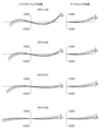
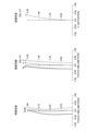
- FIG. 4 is a diagram showing various aberrations (spherical aberration, field curvature, and distortion aberration) of the attachment optical system according to the first embodiment when silicone is used as the immersion liquid.
- FIG. 5 is a diagram showing various aberrations of the attachment optical system according to the first embodiment when glycerin is used as the immersion liquid.
- FIG. 6 is a diagram showing various aberrations of the attachment optical system according to the first embodiment when oil is used as the immersion liquid.
- FIG. 7 is a diagram showing various aberrations of the attachment optical system according to the first embodiment when water is used as the immersion liquid.
- FIG. 4 is a diagram showing various aberrations (spherical aberration, field curvature, and distortion aberration) of the attachment optical system according to the first embodiment when silicone is used as the immersion liquid.
- FIG. 5 is a diagram showing various aberrations of the attachment optical system according to the first embodiment when glycerin is used as the immersion liquid.
- FIG. 6 is a diagram showing various aberrations
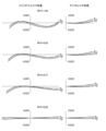
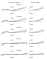
- FIG. 8 is a diagram showing coma aberration (meridional coma aberration and sagittal coma aberration) of the attachment optical system according to the first embodiment when silicone is used as the immersion liquid.
- FIG. 9 is a diagram showing coma aberration of the attachment optical system according to the first embodiment when glycerin is used as the immersion liquid.
- FIG. 10 is a diagram showing coma aberration of the attachment optical system according to the first embodiment when oil is used as the immersion liquid.
- FIG. 11 shows the coma aberration of the attachment optical system in the first embodiment when water is used as the immersion liquid.
- Each aberration diagram shows various aberrations when the objective lens and the imaging lens are combined with the attachment optical system.
- the vertical axis indicates the value normalized with the maximum value of the entrance pupil radius set to 1
- the horizontal axis indicates the aberration value [mm] for each light ray.
- the solid line indicates the sagittal image surface for each wavelength
- the dashed line indicates the meridional image surface for each wavelength.
- the vertical axis indicates the image height [mm]
- the horizontal axis indicates the aberration value [mm].
- the vertical axis indicates the image height [mm]
- the horizontal axis indicates the aberration ratio as a percentage (%).
- Each coma aberration diagram shows the aberration value when the image height ratio RFH (Relative Field Height) is 0.00 to 1.00. Note that the same symbols as in this embodiment are used in the aberration diagrams of each embodiment shown below, and duplicate explanations will be omitted.
- the attachment optical system of the first embodiment has excellent imaging performance, with various aberrations being well corrected depending on the type of immersion liquid.
- FIG. 12 is a cross-sectional view showing the configuration of the attachment optical system and the objective lens according to the second embodiment.
- the attachment optical system AL(2) according to the second embodiment is detachably attached between the objective lens OL(2) according to the second embodiment and the imaging lens (not shown in FIG. 12).
- the objective lens OL(2) according to the second embodiment receives light from the object (sample SA) and converts it into parallel light.
- Light (parallel light) from the objective lens OL(2) according to the second embodiment is incident on the attachment optical system AL(2) according to the second embodiment.
- the space between the tip of the objective lens OL(2) according to the second embodiment and the cover glass CV that covers the object is filled with air.
- the space between the cover glass CV and the object is filled with an immersion liquid M.
- the immersion liquid M for example, silicone, glycerin, oil, water, or the like is used.
- the objective lens OL(2) in the second embodiment is composed of the first to eighth lenses L1 to L8.
- the first to eighth lenses L1 to L8 have the same configuration as the first to eighth lenses L1 to L8 of the objective lens OL(1) in the first embodiment, and detailed description will be omitted.
- the attachment optical system AL(2) in the second embodiment is composed of a cemented lens CL11, which is composed of a biconcave negative lens L11 and a meniscus positive lens L12 with a convex surface facing the object side, arranged in order from the object side (the objective lens OL(2) side) along the optical axis, and a biconvex positive lens L13.
- the cemented lens CL11 having negative refractive power corresponds to the first optical element EL1 described above
- the positive lens L13 corresponds to the second optical element EL2 described above.
- the cemented lens CL11 is configured to be able to move along the optical axis by rotating the correction collar 28 (see FIG. 2) around the optical axis according to the type and depth of the immersion liquid M, the thickness of the cover glass CV, etc.
- the rear focal position FP of the objective lens OL(2) in the second embodiment is located near the image side (imaging lens side) of the positive lens L13.
- Table 2 below lists the values of the attachment optical system and objective lens in the second embodiment. Note that the first surface is the object surface, and the second and eighteenth surfaces are virtual surfaces.
- FIG. 13 is a diagram showing various aberrations (spherical aberration, field curvature, and distortion aberration) of the attachment optical system according to the second embodiment when silicone is used as the immersion liquid.
- FIG. 14 is a diagram showing various aberrations of the attachment optical system according to the second embodiment when glycerin is used as the immersion liquid.
- FIG. 15 is a diagram showing various aberrations of the attachment optical system according to the second embodiment when oil is used as the immersion liquid.
- FIG. 16 is a diagram showing various aberrations of the attachment optical system according to the second embodiment when water is used as the immersion liquid.
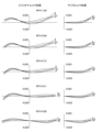
- FIG. 17 is a diagram showing coma aberrations (meridional coma aberration and sagittal coma aberration) of the attachment optical system according to the second embodiment when silicone is used as the immersion liquid.
- FIG. 18 is a diagram showing coma aberrations of the attachment optical system according to the second embodiment when glycerin is used as the immersion liquid.
- FIG. 19 is a diagram showing coma aberrations of the attachment optical system according to the second embodiment when oil is used as the immersion liquid.
- FIG. 20 shows the coma aberration of the attachment optical system in the second embodiment when water is used as the immersion liquid.
- the attachment optical system of the second embodiment has excellent imaging performance, with various aberrations being well corrected depending on the type of immersion liquid.
- FIG. 21 is a cross-sectional view showing the configuration of the attachment optical system and the objective lens according to the third embodiment.
- the attachment optical system AL(3) according to the third embodiment is detachably attached between the objective lens OL(3) according to the third embodiment and the imaging lens (not shown in FIG. 21).
- the objective lens OL(3) according to the third embodiment receives light from the object (sample SA) and converts it into parallel light.
- Light (parallel light) from the objective lens OL(3) according to the third embodiment is incident on the attachment optical system AL(3) according to the third embodiment.
- the space between the tip of the objective lens OL(3) according to the third embodiment and the cover glass CV that covers the object is filled with air.
- the space between the cover glass CV and the object is filled with immersion liquid M. Water is used as the immersion liquid M.
- the objective lens OL(3) in the third embodiment is composed of first to eighth lenses L1 to L8 arranged in order from the object side along the optical axis.
- the first lens L1, second lens L2, fifth lens L5, and eighth lens L8 are biconvex positive lenses.
- the third lens L3, fourth lens L4, and seventh lens L7 are biconcave negative lenses.
- the sixth lens L6 is a meniscus positive lens with its concave surface facing the object side.
- the second lens L2 and the third lens L3 are cemented together.
- the fourth lens L4 and the fifth lens L5 are cemented together.
- the attachment optical system AL(3) according to the third embodiment has the same configuration as the attachment optical system AL(2) according to the second embodiment, and detailed description thereof will be omitted.
- the cemented lens CL11 having negative refractive power corresponds to the first optical element EL1 described above
- the positive lens L13 corresponds to the second optical element EL2 described above.
- the cemented lens CL11 is moved along the optical axis by rotating the correction ring 28 (see FIG. 2) around the optical axis according to the depth of the immersion liquid M. Specifically, when the depth of the immersion liquid M becomes deeper, the cemented lens CL11 is moved along the optical axis toward the object side (the objective lens OL(3) side) by rotating the correction ring 28 around the optical axis.
- the rear focal position FP of the objective lens OL(3) in the third embodiment is located near the image side (imaging lens side) of the positive lens L13.
- Table 3 lists the values of the attachment optical system and objective lens in the third embodiment. Note that surface 1 is the object surface, and surface 18 is the virtual surface.
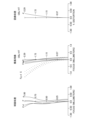
- FIG. 22 is a diagram showing various aberrations (spherical aberration, field curvature, and distortion aberration) of the attachment optical system according to the third embodiment when observing an object at a depth of 0.5 mm.
- FIG. 23 is a diagram showing various aberrations of the attachment optical system according to the third embodiment when observing an object at a depth of 2.5 mm.
- FIG. 24 is a diagram showing various aberrations of the attachment optical system according to the third embodiment when observing an object at a depth of 3.5 mm.
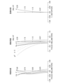
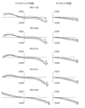
- FIG. 25 is a diagram showing coma aberrations (meridional coma aberration and sagittal coma aberration) of the attachment optical system according to the third embodiment when observing an object at a depth of 0.5 mm.
- FIG. 23 is a diagram showing various aberrations of the attachment optical system according to the third embodiment when observing an object at a depth of 2.5 mm.
- FIG. 24 is a diagram showing various aberrations of the attachment optical system according to the third
- FIG. 26 is a diagram showing coma aberrations of the attachment optical system according to the third embodiment when observing an object at a depth of 2.5 mm.
- FIG. 27 is a diagram showing coma aberrations of the attachment optical system according to the third embodiment when observing an object at a depth of 3.5 mm.
- the vertical axis indicates the object height [mm] and the horizontal axis indicates the aberration value [mm].
- the vertical axis indicates the object height [mm] and the horizontal axis indicates the proportion of the aberration as a percentage (% value). From each aberration diagram, it can be seen that the attachment optical system of the third embodiment has excellent imaging performance, with various aberrations being well corrected according to the depth of the immersion liquid.
- FIG. 28 is a cross-sectional view showing the configuration of the attachment optical system and the objective lens according to the fourth embodiment.
- the attachment optical system AL(4) according to the fourth embodiment is detachably attached between the objective lens OL(4) according to the fourth embodiment and the imaging lens (not shown in FIG. 28).
- the objective lens OL(4) according to the fourth embodiment receives light from the object (sample SA) and converts it into parallel light.
- Light (parallel light) from the objective lens OL(4) according to the fourth embodiment is incident on the attachment optical system AL(4) according to the fourth embodiment.
- the space between the tip of the objective lens OL(4) according to the fourth embodiment and the cover glass CV that covers the object is filled with air.
- the space between the cover glass CV and the object is filled with an immersion liquid M.
- silicone, glycerin, oil, water, etc. are used as the immersion liquid M.
- the objective lens OL(4) in the fourth embodiment is composed of the first to eighth lenses L1 to L8.
- the first to eighth lenses L1 to L8 have the same configuration as the first to eighth lenses L1 to L8 of the objective lens OL(1) in the first embodiment, and detailed description will be omitted.
- the attachment optical system AL(4) in the fourth embodiment is composed of a diffractive optical element DL1 having positive refractive power and a diffractive optical element DL2 having negative refractive power, which are arranged in order from the object side (the objective lens OL(4) side) along the optical axis.
- the diffractive optical element DL2 having negative refractive power corresponds to the first optical element EL1 described above
- the diffractive optical element DL1 having positive refractive power corresponds to the second optical element EL2 described above.
- the diffractive optical element DL1 having positive refractive power is configured to be able to move along the optical axis by rotating the correction collar 28 (see FIG. 2) around the optical axis depending on the type and depth of the immersion liquid M, the thickness of the cover glass CV, etc.
- the diffractive optical element DL1 having positive refractive power is configured to include, in order from the object side (the objective lens OL(4) side) along the optical axis, a first parallel plate PP1, a first optical element element DE1 bonded to the first parallel plate PP1, a second optical element element DE2 bonded to the first optical element element DE1, and a second parallel plate PP2 bonded to the second optical element element DE2.
- the first optical element element DE1 and the second optical element DE2 have different refractive indices, etc.
- a ring-shaped diffractive optical surface (not shown) that constitutes a diffraction grating is formed at the interface between the first optical element element DE1 and the second optical element element DE2. In this way, the diffractive optical element DL1 having positive refractive power is a contact multi-layer type diffractive optical element.
- the diffractive optical element DL2 having negative refractive power is configured to include, in order from the object side (the objective lens OL(4) side) along the optical axis, a third parallel plate PP3, a third optical element element DE3 bonded to the third parallel plate PP3, a fourth optical element element DE4 bonded to the third optical element element DE3, and a fourth parallel plate PP4 bonded to the fourth optical element element DE4.
- the third optical element element DE3 and the fourth optical element element DE4 have different refractive indices, etc.
- a ring-shaped diffractive optical surface (not shown) that constitutes a diffraction grating is formed at the interface between the third optical element element DE3 and the fourth optical element element DE4. In this way, the diffractive optical element DL2 having negative refractive power is also a contact multi-layer type diffractive optical element.
- the rear focal position FP of the objective lens OL(4) in the fourth embodiment is disposed between the diffractive optical element DL1 having a positive refractive power and the diffractive optical element DL2 having a negative refractive power.
- Table 4 lists the values of the attachment optical system and objective lens in the fourth embodiment. Note that the first surface is the object surface, and the second surface is a virtual surface. Additionally, the 20th and 25th surfaces are diffractive optical surfaces.
- FIG. 29 is a diagram showing various aberrations (spherical aberration, field curvature, and distortion aberration) of the attachment optical system according to the fourth embodiment when silicone is used as the immersion liquid.
- FIG. 30 is a diagram showing various aberrations of the attachment optical system according to the fourth embodiment when glycerin is used as the immersion liquid.
- FIG. 31 is a diagram showing various aberrations of the attachment optical system according to the fourth embodiment when oil is used as the immersion liquid.
- FIG. 32 is a diagram showing various aberrations of the attachment optical system according to the fourth embodiment when water is used as the immersion liquid.
- FIG. 29 is a diagram showing various aberrations (spherical aberration, field curvature, and distortion aberration) of the attachment optical system according to the fourth embodiment when silicone is used as the immersion liquid.
- FIG. 30 is a diagram showing various aberrations of the attachment optical system according to the fourth embodiment when glycerin is used as the immersion liquid.
- FIG. 31 is a diagram showing various aberrations
- FIG. 33 is a diagram showing coma aberration (meridional coma aberration and sagittal coma aberration) of the attachment optical system according to the fourth embodiment when silicone is used as the immersion liquid.
- FIG. 34 is a diagram showing coma aberration of the attachment optical system according to the fourth embodiment when glycerin is used as the immersion liquid.
- FIG. 35 is a diagram showing coma aberration of the attachment optical system according to the fourth embodiment when oil is used as the immersion liquid.
- FIG. 36 shows the coma aberration of the attachment optical system in the fourth embodiment when water is used as the immersion liquid.
- the vertical axis indicates the object height [mm] and the horizontal axis indicates the aberration value [mm].
- the vertical axis indicates the object height [mm] and the horizontal axis indicates the proportion of the aberration as a percentage (% value). From each aberration diagram, it can be seen that the attachment optical system of the fourth embodiment has excellent imaging performance, with various aberrations being well corrected according to the type of immersion liquid.
- the objective lens in each embodiment is an infinity correction type lens. Therefore, the attachment optical system in each embodiment is used in combination with an imaging lens that forms an image from the objective lens.
- An example of an imaging lens used in combination with the attachment optical system will be described with reference to FIG. 37 and Table 5.
- FIG. 37 is a cross-sectional view showing the configuration of an imaging lens used in combination with the attachment optical system in each embodiment.
- the various aberration diagrams of the attachment optical system in each embodiment are when used in combination with the objective lens in each embodiment and this imaging lens.
- FIG. 37 is composed of, in order from the object side, a cemented lens in which a biconvex positive lens L51 and a biconcave negative lens L52 are cemented together, and a cemented lens in which a biconvex positive lens L53 and a biconcave negative lens L54 are cemented together.
- the imaging lens IL is arranged on the image side of the objective lens in each embodiment.
- FIG. 37 also shows the entrance pupil plane Pu of the imaging lens IL.
- Table 5 lists the values of the imaging lens' specifications.
- f' indicates the focal length of the imaging lens.
- the surface number, R, D, nd, and vd are the same as those explained in Tables 1 to 4 above.
- Conditional expression (1) 2 ⁇
- Conditional expression (2) 35 ⁇ dP ⁇ 101
- Conditional expression (3) 0 ⁇ dP ⁇ dN ⁇ 30
- Conditional expression (4) 0.1 ⁇ A/TLA ⁇ 4.5
- Conditional expression (5) 0.05 ⁇ TLA/TLB ⁇ 0.75
- the second optical element EL2 is a single positive lens, but is not limited to this.
- the second optical element EL2 may be a cemented lens having positive refractive power in which a positive lens and a negative lens are cemented together, or may be a cemented lens having at least a positive lens.
- the negative lens L11 is configured to be movable along the optical axis, but this is not limited to the above.
- the positive lens L12 may be configured to be movable along the optical axis, and the negative lens L11 and the positive lens L12 may each be configured to be movable along the optical axis.
- the negative lens L11 may be configured to be movable not only in a direction along the optical axis, but also in a direction perpendicular to the optical axis.
- the positive lens L12 may be configured to be movable in a direction perpendicular to the optical axis
- the negative lens L11 and the positive lens L12 may each be configured to be movable in a direction perpendicular to the optical axis.
- the cemented lens CL11 is configured to be movable along the optical axis, but this is not limited to the above.
- the positive lens L13 may be configured to be movable along the optical axis, and the cemented lens CL11 and the positive lens L13 may each be configured to be movable along the optical axis.
- the cemented lens CL11 may be configured to be movable not only in the direction along the optical axis, but also in a direction perpendicular to the optical axis.
- the positive lens L13 may be configured to be movable in the direction perpendicular to the optical axis, and the cemented lens CL11 and the positive lens L13 may each be configured to be movable in the direction perpendicular to the optical axis.
- the diffractive optical element DL1 having positive refractive power is configured to be movable along the optical axis, but this is not limited to the above.
- the diffractive optical element DL2 having negative refractive power may be configured to be movable along the optical axis
- the diffractive optical element DL1 having positive refractive power and the diffractive optical element DL2 having negative refractive power may each be configured to be movable along the optical axis.
- the diffractive optical element DL1 having positive refractive power may be configured to be movable in a direction perpendicular to the optical axis, not limited to the direction along the optical axis.
- the diffractive optical element DL2 having negative refractive power may be configured to be movable in a direction perpendicular to the optical axis
- the diffractive optical element DL1 having positive refractive power and the diffractive optical element DL2 having negative refractive power may each be configured to be movable in a direction perpendicular to the optical axis.
Landscapes
- Physics & Mathematics (AREA)
- Chemical & Material Sciences (AREA)
- Analytical Chemistry (AREA)
- General Physics & Mathematics (AREA)
- Optics & Photonics (AREA)
- Health & Medical Sciences (AREA)
- General Health & Medical Sciences (AREA)
- Ophthalmology & Optometry (AREA)
- Radiology & Medical Imaging (AREA)
- Surgery (AREA)
- Lenses (AREA)
Abstract
アタッチメント光学系(AL)は、物体からの光を受けて平行光にする対物レンズ(OL)と、対物レンズ(OL)からの光を結像させる結像レンズとの間に着脱可能に装着される顕微鏡用のアタッチメント光学系であって、負の屈折力を有する第1の光学素子(EL1)と、正の屈折力を有する第2の光学素子(EL2)とを有している。
Description
本発明は、顕微鏡用のアタッチメント光学系に関する。
従来から、物体からの光を受けて平行光にする対物レンズと、対物レンズからの光を結像させる結像レンズとを有する顕微鏡が種々提案されている(例えば、特許文献1を参照)。このような顕微鏡では、諸収差を良好に補正することが求められている。
本発明に係るアタッチメント光学系は、物体からの光を受けて平行光にする対物レンズと、前記対物レンズからの光を結像させる結像レンズとの間に着脱可能に装着される顕微鏡用のアタッチメント光学系であって、負の屈折力を有する第1の光学素子と、正の屈折力を有する第2の光学素子とを有する。
以下、本発明に係る好ましい実施形態について説明する。まず、本実施形態に係るアタッチメント光学系を装着可能な共焦点蛍光顕微鏡について説明する。図1に示すように、共焦点蛍光顕微鏡1は、光源ユニット6からの照明用レーザ光を試料SA上に導く励起光導入部2と、試料SA上に集光されるレーザ光を偏向して試料SA上で走査する走査装置3と、試料SAからの光強度信号を検出する光検出装置5と、試料SAからの光を光検出装置5に導く集光光学系4とを有して構成される。
光源ユニット6は、共焦点蛍光顕微鏡1に設けられてもよく、共焦点蛍光顕微鏡1と別体に設けられてもよい。光源ユニット6は、レーザ光源(図示せず)およびビーム径調整機構(図示せず)等を有して構成される。光源ユニット6は、照明用レーザ光を発振させる。
励起光導入部2は、コリメータレンズ21と、ダイクロイックミラー22と、結像レンズ23と、対物レンズ24とを有して構成される。コリメータレンズ21およびダイクロイックミラー22は、顕微鏡本体10における鏡筒部11の上部に設けられた顕微鏡筐体部12の内部に配設される。なお、光源ユニット6と顕微鏡筐体部12とは、コネクタC3,C4を用いて光ファイバ69により接続されている。コリメータレンズ21は、光源ユニット6から発振されたレーザ光(光束)を平行光に変換する。ダイクロイックミラー22は、コリメータレンズ21からのレーザ光を試料SAに向けて反射する。結像レンズ23と対物レンズ24によって、ダイクロイックミラー22で反射したレーザ光が試料SA上に集光される。結像レンズ23は、顕微鏡本体10における鏡筒部11の内部に配設される。なお、結像レンズ23は、第2対物レンズとも称される。対物レンズ24は、鏡筒部11の下部に設けられたレボルバ15に着脱可能に取り付けられる。
また、図2に示すように、対物レンズ24を、アタッチメント光学系25とともに、レボルバ15に着脱可能に取り付けることも可能である。これにより、アタッチメント光学系25は、対物レンズ24と結像レンズ23との間に着脱可能に装着される。対物レンズ24と結像レンズ23との間にアタッチメント光学系25が装着される場合、結像レンズ23とアタッチメント光学系25と対物レンズ24によって、ダイクロイックミラー22で反射したレーザ光が試料SA上に集光される。なお、アタッチメント光学系25を構成する光学素子は、筒状に形成された光学素子筐体26に収容されている。光学素子筐体26の一端側(対物レンズ24側)に第1のネジ部27aが形成され、光学素子筐体26の他端側(対物レンズ24側と反対側)に第2のネジ部27bが形成される。第1のネジ部27aは、対物レンズ24のネジ部(図示せず)と螺合可能な雌ネジである。第2のネジ部27bは、レボルバ15のネジ部(図示せず)と螺合可能な雄ネジである。また、光学素子筐体26の側部に、収差補正のための回転操作が行われる補正環28が設けられる。
図1に示すように、走査装置3は、走査機構(スキャナ)31と、走査光学系32とを備えて構成される。走査装置3は、顕微鏡筐体部12の内部におけるダイクロイックミラー22と結像レンズ23との間に配設される。走査機構(スキャナ)31は、例えばガルバノミラー(図示せず)またはレゾナントミラー(図示せず)を有して構成される。走査機構(スキャナ)31は、入射するレーザ光を偏向する。つまり、走査機構(スキャナ)31は、試料SA上に集光されるレーザ光を偏向して試料SA上で走査する。走査光学系32は、走査機構(スキャナ)31と結像レンズ23との間に設けられる光学系である。また、走査光学系32は、走査光学系32の焦点位置が試料SA(試料SAの走査面)と共役な結像面13(1次像面とも称される)に位置する光学系である。
集光光学系4は、対物レンズ24と、結像レンズ23と、全反射ミラー41と、集光レンズ42とを備えて構成される。対物レンズ24は、試料SAで発生した蛍光を受けて平行光にする。結像レンズ23は、対物レンズ24から射出された蛍光(平行光)を一旦結像面13(1次像面)に集光して結像させる。また、対物レンズ24と結像レンズ23との間にアタッチメント光学系25が装着される場合、結像レンズ23は、アタッチメント光学系25を通過した対物レンズ24からの蛍光を一旦結像面13に集光して結像させる。これにより、結像レンズ23を通過した試料SAからの蛍光は、一旦結像面13に集光し、走査装置3およびダイクロイックミラー22を通って全反射ミラー41に達する。全反射ミラー41および集光レンズ42は、顕微鏡筐体部12の内部におけるダイクロイックミラー22の上方に配設される。全反射ミラー41は、結像レンズ23を通過した試料SAからの蛍光を反射させる。集光レンズ42は、全反射ミラー41で反射した蛍光を、ピンホール51(開口)を有する遮光板52上に集光する。
光検出装置5は、ピンホール51を有する遮光板52と、光ファイバ53と、検出ユニット55とを備えて構成される。光ファイバ53は、コネクタC1,C2を用いて顕微鏡筐体部12と検出ユニット55とに接続される。光ファイバ53には、ピンホール51を通過した光(蛍光)が入射する。検出ユニット55は、ピンホール51および光ファイバ53を通過した光(蛍光)を検出する。検出ユニット55には、ケーブル56を介して処理ユニット57が電気的に接続される。処理ユニット57により検出ユニット55で検出された検出信号に基づく(試料SAの)画像処理が行われ、処理ユニット57の画像処理により得られた試料SAの観察画像が図示しないモニターに表示される。
なお、走査装置3からのレーザ光は、一旦結像面13(1次像面)に集光し、再度、結像レンズ23と対物レンズ24によって試料SA上に集光するように構成される。また、対物レンズ24と結像レンズ23との間にアタッチメント光学系25が装着される場合、走査装置3からのレーザ光は、一旦結像面13に集光し、再度、結像レンズ23とアタッチメント光学系25と対物レンズ24によって試料SA上に集光するように構成される。すなわち、試料SAの走査面、結像面13、およびピンホール51が互いに共役の関係にある。そのため、結像レンズ23と(アタッチメント光学系25と)対物レンズ24によって試料SA上に集光するように構成されることで、試料SAからの光(蛍光)のうち、試料SAの走査面上で発生した蛍光をピンホール51に通過させることが可能になる。
本実施形態に係るアタッチメント光学系を装着可能な顕微鏡の一例として、共焦点蛍光顕微鏡1について説明したが、これに限られるものではない。例えば、本実施形態に係るアタッチメント光学系を装着可能な顕微鏡は、多光子励起顕微鏡や、超解像顕微鏡、観察顕微鏡等であってもよい。また、共焦点蛍光顕微鏡1は、正立顕微鏡であってもよく、倒立顕微鏡であってもよい。
このような共焦点蛍光顕微鏡1の対物レンズ24と結像レンズ23との間に装着可能なアタッチメント光学系25として、以降で述べるアタッチメント光学系ALを用いることが可能である。また、このような共焦点蛍光顕微鏡1の対物レンズ24および結像レンズ23として、以降で述べる対物レンズOLおよび結像レンズILを用いることが可能である。
次に、本実施形態に係るアタッチメント光学系ALについて説明する。本実施形態に係るアタッチメント光学系ALの一例として、図3に示すアタッチメント光学系AL(1)は、負の屈折力を有する第1の光学素子EL1と、正の屈折力を有する第2の光学素子EL2とを有している。対物レンズOLと結像レンズILとの間に、本実施形態に係るアタッチメント光学系ALを着脱可能に装着することで、1種類の対物レンズで複数種類の浸液に対応する場合に、浸液の種類に応じて発生する軸上色収差と球面収差を良好に補正することができる。また、対物レンズOLと結像レンズILとの間に、本実施形態に係るアタッチメント光学系ALを着脱可能に装着することで、浸液の深さに応じて発生する収差(軸上色収差や球面収差)を良好に補正することが可能になる。本実施形態に係るアタッチメント光学系ALは、図12に示すアタッチメント光学系AL(2)でも良く、図21に示すアタッチメント光学系AL(3)でも良く、図28に示すアタッチメント光学系AL(4)でも良い。
本実施形態に係るアタッチメント光学系ALにおいて、第1の光学素子EL1および第2の光学素子EL2のうち少なくとも一方が光軸に沿って移動可能であってもよい。これにより、試料または浸液の屈折率やアッベ数に応じて発生する軸上色収差を良好に補正することができる。なお、第1の光学素子EL1および第2の光学素子EL2のうちいずれか一方が光軸に沿って移動可能であってもよい。第1の光学素子EL1と第2の光学素子EL2とがそれぞれ光軸に沿って移動可能であってもよい。
本実施形態に係るアタッチメント光学系ALにおいて、第1の光学素子EL1および第2の光学素子EL2のうち少なくとも一方が光軸と垂直な方向に移動可能であってもよい。これにより、対物レンズや結像レンズ(顕微鏡)の偏芯に基づく収差を良好に補正することができる。なお、第1の光学素子EL1および第2の光学素子EL2のうちいずれか一方が光軸と垂直な方向に移動可能であってもよい。第1の光学素子EL1と第2の光学素子EL2とがそれぞれ光軸と垂直な方向に移動可能であってもよい。
本実施形態に係るアタッチメント光学系ALは、以下の条件式(1)を満足してもよい。
2<|fA|/TLA<10000 ・・・(1)
但し、fA:アタッチメント光学系ALの焦点距離
TLA:アタッチメント光学系ALの全長
2<|fA|/TLA<10000 ・・・(1)
但し、fA:アタッチメント光学系ALの焦点距離
TLA:アタッチメント光学系ALの全長
条件式(1)は、アタッチメント光学系ALの焦点距離と、アタッチメント光学系ALの全長との適切な関係を規定するものである。条件式(1)を満足することで、アタッチメント光学系ALを装着しても顕微鏡の総合倍率が大きく変化しないため、アタッチメント光学系ALの装着による顕微鏡の視野範囲の変動を抑えることができる。なお、条件式(1)の下限値を25、さらに100に設定することで、本実施形態の効果をより確実なものとすることができる。条件式(1)の上限値を7000、5000、3000、さらに1500に設定することで、本実施形態の効果をより確実なものとすることができる。
本実施形態に係るアタッチメント光学系ALにおいて、光軸に沿って対物レンズOL側から順に、第1の光学素子EL1と、第2の光学素子EL2とが配置されてもよい。これにより、アタッチメント光学系ALを通過する光線が光軸から離れるため、球面収差を良好に補正することができる。また、試料や浸液の種類に応じて発生する収差(軸上色収差や球面収差)を補正することが可能である。
本実施形態に係るアタッチメント光学系ALにおいて、第2の光学素子EL2は、1個の正レンズもしくは、少なくとも正レンズを有する1個の接合レンズであり、以下の条件式(2)を満足してもよい。
35<νdP<101 ・・・(2)
但し、νdP:正レンズのアッベ数
35<νdP<101 ・・・(2)
但し、νdP:正レンズのアッベ数
条件式(2)は、正レンズのアッベ数について、適切な範囲を規定するものである。条件式(2)を満足することで、軸上色収差と球面収差を良好に補正することができる。なお、条件式(2)の下限値を40、さらに45に設定することで、本実施形態の効果をより確実なものとすることができる。条件式(2)の上限値を96、90、さらに80に設定することで、本実施形態の効果をより確実なものとすることができる。また、第2の光学素子EL2は、1個の正レンズであってもよい。
本実施形態に係るアタッチメント光学系ALにおいて、第1の光学素子EL1は、1個の負レンズもしくは、少なくとも負レンズを有する1個の接合レンズであり、第2の光学素子EL2は、1個の正レンズもしくは、少なくとも正レンズを有する1個の接合レンズであり、以下の条件式(3)を満足してもよい。
0≦νdP-νdN<30 ・・・(3)
但し、νdP:正レンズのアッベ数
νdN:負レンズのアッベ数
0≦νdP-νdN<30 ・・・(3)
但し、νdP:正レンズのアッベ数
νdN:負レンズのアッベ数
条件式(3)は、正レンズのアッベ数と、負レンズのアッベ数との適切な関係を規定するものである。条件式(3)を満足することで、軸上色収差を良好に補正することができる。条件式(3)の対応値が上記範囲を外れてしまうと、正レンズと負レンズとのアッベ数の差が大きくなりすぎるため、アタッチメント光学系ALによる収差補正が過剰となり、軸上色収差を良好に補正することが困難になる。なお、条件式(3)の上限値を25、20、さらに15に設定することで、本実施形態の効果をより確実なものとすることができる。また、第2の光学素子EL2は、1個の正レンズであってもよい。
本実施形態に係るアタッチメント光学系ALにおいて、第1の光学素子EL1は、負の屈折力を有する回折光学素子であり、第2の光学素子EL2は、正の屈折力を有する回折光学素子であり、光軸に沿って対物レンズOL側から順に、正の屈折力を有する回折光学素子と、負の屈折力を有する回折光学素子とが配置されてもよい。これにより、回折現象を利用することで、試料または浸液の屈折率やアッベ数に応じて発生する軸上色収差を良好に補正することができる。
本実施形態に係るアタッチメント光学系ALは、以下の条件式(4)を満足してもよい。
0.1<δA/TLA<4.5 ・・・(4)
但し、δA:アタッチメント光学系ALにおける対物レンズOLに最も近い光学面から対物レンズOLの後側焦点位置FPまでの光軸上の距離
TLA:アタッチメント光学系ALの全長
0.1<δA/TLA<4.5 ・・・(4)
但し、δA:アタッチメント光学系ALにおける対物レンズOLに最も近い光学面から対物レンズOLの後側焦点位置FPまでの光軸上の距離
TLA:アタッチメント光学系ALの全長
条件式(4)は、アタッチメント光学系ALにおける対物レンズOLに最も近い光学面から対物レンズOLの後側焦点位置FPまでの光軸上の距離と、アタッチメント光学系ALの全長との適切な関係を規定するものである。なお、アタッチメント光学系ALにおける対物レンズOLに最も近い光学面よりも結像レンズIL側に、対物レンズOLの後側焦点位置FPが配置されてもよい。アタッチメント光学系ALにおける対物レンズOLに最も近い光学面よりも対物レンズOL側に、対物レンズOLの後側焦点位置FPが配置されてもよい。アタッチメント光学系ALにおける対物レンズOLに最も近い光学面から対物レンズOLの後側焦点位置FPまでの光軸上の距離は、アタッチメント光学系ALにおける対物レンズOLに最も近い光学面から対物レンズOLの後側焦点位置FPまでの光軸上の距離の絶対値を示すものである。条件式(4)を満足することで、倍率色収差を小さく抑えつつ、試料または浸液の屈折率やアッベ数に応じて発生する軸上色収差を良好に補正することができる。なお、条件式(4)の下限値を0.2、0.3、さらに0.5に設定することで、本実施形態の効果をより確実なものとすることができる。条件式(4)の上限値を4、3.5、さらに3に設定することで、本実施形態の効果をより確実なものとすることができる。
本実施形態に係るアタッチメント光学系ALは、以下の条件式(5)を満足してもよい。
0.05<TLA/TLB<0.75 ・・・(5)
但し、TLA:アタッチメント光学系ALの全長
TLB:対物レンズOLの全長
0.05<TLA/TLB<0.75 ・・・(5)
但し、TLA:アタッチメント光学系ALの全長
TLB:対物レンズOLの全長
条件式(5)は、アタッチメント光学系ALの全長と、対物レンズOLの全長との適切な関係を規定するものである。条件式(5)を満足することで、アタッチメント光学系ALの全長が短くなるため、アタッチメント光学系ALの装着による対物レンズOLと試料との間隔の変化を最小限に抑えることができる。そのため、アタッチメント光学系ALとともに対物レンズOLを取り付け可能な顕微鏡として、既存の顕微鏡を用いることができる。なお、条件式(5)の下限値を0.1、さらに0.15に設定することで、本実施形態の効果をより確実なものとすることができる。条件式(5)の上限値を0.6、さらに0.5に設定することで、本実施形態の効果をより確実なものとすることができる。
また、本実施形態において、対物レンズOLの全長がアタッチメント光学系ALの全長の整数倍(例えば、2倍、3倍、4倍、5倍、6倍等)となるように、アタッチメント光学系ALが設計されてもよい。なお、現実の対物レンズおよびアタッチメント光学系において、対物レンズの全長とアタッチメント光学系の全長の比率を厳密に整数倍とすることは、製造技術上あるいは計測技術上、極めて困難である。そのため、本実施形態の趣旨を逸脱しない範囲で、対物レンズの全長とアタッチメント光学系の全長の比率は略整数倍であればよい。すなわち、本実施形態において、整数倍とは略整数倍を含む概念であり、少なくとも製造技術上の精度の範囲が得られる範囲までが含まれる。例えば、対物レンズの全長とアタッチメント光学系の全長の比率は、(数学的な)整数倍±10%の範囲の倍率、整数倍±5%の範囲の倍率、整数倍±3%の範囲の倍率、整数倍±1%の範囲の倍率等であってもよく、これらは略整数倍として、本実施形態における整数倍の範囲に含まれる。
以下、本実施形態に係るアタッチメント光学系ALの実施例を図面に基づいて説明する。図3、図12、図21、および図28は、第1~第4実施例に係るアタッチメント光学系AL{AL(1)~AL(4)}および対物レンズOL{OL(1)~OL(4)}の構成を示す光路図である。これら図3、図12、図21、および図28において、光学素子を符号Lと数字(もしくはアルファベット)の組み合わせにより、それぞれ表している。この場合において、符号、数字の種類および数が大きくなって煩雑化するのを防止するため、実施例毎にそれぞれ独立して符号と数字の組み合わせを用いてレンズ等を表している。このため、実施例間で同一の符号と数字の組み合わせが用いられていても、同一の構成であることを意味するものでは無い。
以下に表1~表4を示すが、この内、表1は第1実施例、表2は第2実施例、表3は第3実施例、表4は第4実施例における各諸元データを示す表である。各実施例では収差特性の算出対象として、d線(波長λ=587.6nm)、C線(波長λ=656.3nm)、F線(波長λ=486.1nm)、g線(波長λ=435.8nm)を選んでいる。
[全体諸元]の表において、NAは、アタッチメント光学系が装着された状態での対物レンズの開口数を示す。βは、アタッチメント光学系が装着された状態での対物レンズの倍率を示す。fは、アタッチメント光学系の焦点距離を示す。φは、アタッチメント光学系の瞳径を示す。TLAは、アタッチメント光学系の全長(アタッチメント光学系における対物レンズに最も近い光学面から結像レンズに最も近い光学面までの光軸上の距離)を示す。TLBは、対物レンズの全長(対物レンズにおける最も物体側のレンズ面から最も像側のレンズ面までの光軸上の距離)を示す。δAは、アタッチメント光学系における対物レンズに最も近い光学面から対物レンズの後側焦点位置までの光軸上の距離を示す。
[レンズデータ]の表において、面番号は物体側からのレンズ面の順序を示し、Rは各面番号に対応する曲率半径(物体側に凸のレンズ面の場合を正の値としている)、Dは各面番号に対応する光軸上のレンズ厚もしくは空気間隔、ndは各面番号に対応する光学材料のd線(波長λ=587.6nm)に対する屈折率、νdは各面番号に対応する光学材料のd線を基準とするアッベ数をそれぞれ示す。曲率半径の「∞」は平面又は開口を示す。また、空気の屈折率nd=1.00000の記載は省略している。光学面が回折光学面である場合には面番号に*印を付して、曲率半径Rの欄には近軸曲率半径を示している。
アタッチメント光学系が回折光学素子を有する場合、[回折光学面データ]において、位相関数法を用いて計算した回折光学面の位相係数を示す。位相係数の基準波長は587.6nmとする。位相係数の「E-n」は、「×10-n」を示す。例えば、1.234E-05=1.234×10⁻⁵である。回折光学面の形状を決める位相多項式は、次の数式(A)で表される。
[可変間隔データ]の表には、[レンズデータ]の表において面間隔が(Di)となっている面番号iでの面間隔を示す。また、[可変間隔データ]の表には、浸液の種類または深さに応じた面間隔を示す。なお、[可変間隔データ]の表において、ndMは、対応する浸液のd線(波長λ=587.6nm)に対する屈折率を示す。νdMは、対応する浸液のd線を基準とするアッベ数を示す。
以下、全ての諸元値において、掲載されている焦点距離f、曲率半径R、面間隔D、その他の長さ等は、特記のない場合一般に「mm」が使われるが、光学系は比例拡大又は比例縮小しても同等の光学性能が得られるので、これに限られるものではない。
ここまでの表の説明は全ての実施例において共通であり、以下での重複する説明は省略する。
(第1実施例)
第1実施例について、図3~図11および表1を用いて説明する。図3は、第1実施例に係るアタッチメント光学系および対物レンズの構成を示す断面図である。第1実施例に係るアタッチメント光学系AL(1)は、第1実施例に係る対物レンズOL(1)と結像レンズ(図3では図示せず)との間に着脱可能に装着される。第1実施例に係る対物レンズOL(1)は、物体(試料SA)からの光を受けて平行光にする。第1実施例に係るアタッチメント光学系AL(1)には、第1実施例に係る対物レンズOL(1)からの光(平行光)が入射する。第1実施例に係る対物レンズOL(1)の先端部と物体を覆うカバーガラスCVとの間は、空気で満たされている。また、カバーガラスCVと物体との間は、浸液Mで満たされている。浸液Mには、例えば、シリコーン、グリセリン、オイル、水等が用いられる。
第1実施例について、図3~図11および表1を用いて説明する。図3は、第1実施例に係るアタッチメント光学系および対物レンズの構成を示す断面図である。第1実施例に係るアタッチメント光学系AL(1)は、第1実施例に係る対物レンズOL(1)と結像レンズ(図3では図示せず)との間に着脱可能に装着される。第1実施例に係る対物レンズOL(1)は、物体(試料SA)からの光を受けて平行光にする。第1実施例に係るアタッチメント光学系AL(1)には、第1実施例に係る対物レンズOL(1)からの光(平行光)が入射する。第1実施例に係る対物レンズOL(1)の先端部と物体を覆うカバーガラスCVとの間は、空気で満たされている。また、カバーガラスCVと物体との間は、浸液Mで満たされている。浸液Mには、例えば、シリコーン、グリセリン、オイル、水等が用いられる。
第1実施例に係る対物レンズOL(1)は、光軸に沿って物体側から順に並んだ、第1~第8レンズL1~L8から構成される。第1レンズL1、第2レンズL2、第5レンズL5、および第8レンズL8は、両凸形状の正レンズである。第3レンズL3、第4レンズL4、および第7レンズL7は、両凹形状の負レンズである。第6レンズL6は、物体側に凹面を向けたメニスカス形状の正レンズである。また、第2レンズL2と第3レンズL3とが接合される。第4レンズL4と第5レンズL5とが接合される。第7レンズL7と第8レンズL8とが接合される。
第1実施例に係るアタッチメント光学系AL(1)は、光軸に沿って物体側(対物レンズOL(1)側)から順に並んだ、物体側に凹面を向けたメニスカス形状の負レンズL11と、物体側に凹面を向けたメニスカス形状の正レンズL12とから構成される。第1実施例において、負レンズL11が前述の第1の光学素子EL1に相当し、正レンズL12が前述の第2の光学素子EL2に相当する。正レンズL12の像側(結像レンズ側)の近傍に、第1実施例に係る対物レンズOL(1)の後側焦点位置FPが配置される。また、浸液Mの種類や深さ、カバーガラスCVの厚さ等に応じて、補正環28(図2を参照)を光軸回りに回転させることで、負レンズL11を光軸に沿って移動させることができるように構成される。
第1実施例において、シリコーンのd線(波長λ=587.6nm)に対する屈折率は1.4041とする。グリセリンのd線(波長λ=587.6nm)に対する屈折率は1.4738とする。オイルのd線(波長λ=587.6nm)に対する屈折率は1.5150とする。水のd線(波長λ=587.6nm)に対する屈折率は1.3326とする。カバーガラスCVのd線(波長λ=587.6nm)に対する屈折率は1.5244とする。
以下の表1に、第1実施例に係るアタッチメント光学系および対物レンズの諸元の値を掲げる。なお、第1面は物体面であり、第2面および第18面は仮想面である。
(表1)
[全体諸元]
NA=0.200 β=4.731
f=-6999.947 φ=16.911
TLA=5.843 TLB=32.00
δA=7.064
[レンズデータ]
面番号 R D nd νd
1 ∞ (D1) (ndM) (νdM)
2 ∞ 10.800 (ndM) (νdM)
3 ∞ 2.000 1.5244 54.3
4 ∞ 19.000
5 81.180 2.762 1.8040 46.6
6 -28.510 0.200
7 19.709 6.427 1.5932 67.9
8 -11.033 2.258 1.5481 45.8
9 12.498 4.417
10 -7.790 1.000 1.7380 32.3
11 42.222 6.661 1.4978 82.6
12 -13.523 0.200
13 -71.317 3.500 1.7408 27.7
14 -15.666 0.200
15 -23.138 1.000 1.6127 44.5
16 52.277 3.376 1.4978 82.6
17 -29.535 0.200
18 ∞ (D18)
19 -43.191 1.000 1.5168 64.1
20 -1610.538 (D20)
21 -584.564 2.360 1.5168 64.1
22 -43.970 100.000
[可変間隔データ]
D1 D18 D20 ndM νdM
シリコーン 1.200 4.457 2.483 1.4041 52.0
グリセリン 1.743 4.287 2.652 1.4738 60.6
オイル 1.502 2.486 4.454 1.5150 43.1
水 0.952 5.766 1.174 1.3326 55.9
図4は、浸液としてシリコーンが用いられる場合の第1実施例に係るアタッチメント光学系の諸収差(球面収差、像面湾曲、および歪曲収差)を示す図である。図5は、浸液としてグリセリンが用いられる場合の第1実施例に係るアタッチメント光学系の諸収差を示す図である。図6は、浸液としてオイルが用いられる場合の第1実施例に係るアタッチメント光学系の諸収差を示す図である。図7は、浸液として水が用いられる場合の第1実施例に係るアタッチメント光学系の諸収差を示す図である。図8は、浸液としてシリコーンが用いられる場合の第1実施例に係るアタッチメント光学系のコマ収差(メリジオナルコマ収差およびサジタルコマ収差)を示す図である。図9は、浸液としてグリセリンが用いられる場合の第1実施例に係るアタッチメント光学系のコマ収差を示す図である。図10は、浸液としてオイルが用いられる場合の第1実施例に係るアタッチメント光学系のコマ収差を示す図である。図11は、浸液として水が用いられる場合の第1実施例に係るアタッチメント光学系のコマ収差を示す図である。
なお、各収差図は、アタッチメント光学系に対物レンズと結像レンズを組み合わせた状態での諸収差を示す。図4~図11の各収差図において、dはd線(波長λ=587.6nm)、CはC線(波長λ=656.3nm)、FはF線(波長λ=486.1nm)、gはg線(波長λ=435.8nm)に対する諸収差をそれぞれ示す。球面収差図において、縦軸は入射瞳半径の最大値を1として規格化して示した値を示し、横軸は各光線における収差の値[mm]を示す。像面湾曲を示す収差図において、実線は各波長に対するサジタル像面を示し、破線は各波長に対するメリジオナル像面を示す。また、像面湾曲を示す収差図において、縦軸は像高[mm]を示し、横軸は収差の値[mm]を示す。歪曲収差図(ディストーション)において、縦軸は像高[mm]を示し、横軸は収差の割合を百分率(%値)で示す。各コマ収差図は、像高比RFH(Relative Field Height)が0.00~1.00のときの収差の値を示す。なお、以下に示す各実施例の収差図においても、本実施例と同様の符号を用い、重複する説明は省略する。
各収差図より、第1実施例に係るアタッチメント光学系は、浸液の種類に応じて諸収差が良好に補正され、優れた結像性能を有していることがわかる。
(第2実施例)
第2実施例について、図12~図20および表2を用いて説明する。図12は、第2実施例に係るアタッチメント光学系および対物レンズの構成を示す断面図である。第2実施例に係るアタッチメント光学系AL(2)は、第2実施例に係る対物レンズOL(2)と結像レンズ(図12では図示せず)との間に着脱可能に装着される。第2実施例に係る対物レンズOL(2)は、物体(試料SA)からの光を受けて平行光にする。第2実施例に係るアタッチメント光学系AL(2)には、第2実施例に係る対物レンズOL(2)からの光(平行光)が入射する。第2実施例に係る対物レンズOL(2)の先端部と物体を覆うカバーガラスCVとの間は、空気で満たされている。また、カバーガラスCVと物体との間は、浸液Mで満たされている。浸液Mには、例えば、シリコーン、グリセリン、オイル、水等が用いられる。
第2実施例について、図12~図20および表2を用いて説明する。図12は、第2実施例に係るアタッチメント光学系および対物レンズの構成を示す断面図である。第2実施例に係るアタッチメント光学系AL(2)は、第2実施例に係る対物レンズOL(2)と結像レンズ(図12では図示せず)との間に着脱可能に装着される。第2実施例に係る対物レンズOL(2)は、物体(試料SA)からの光を受けて平行光にする。第2実施例に係るアタッチメント光学系AL(2)には、第2実施例に係る対物レンズOL(2)からの光(平行光)が入射する。第2実施例に係る対物レンズOL(2)の先端部と物体を覆うカバーガラスCVとの間は、空気で満たされている。また、カバーガラスCVと物体との間は、浸液Mで満たされている。浸液Mには、例えば、シリコーン、グリセリン、オイル、水等が用いられる。
第2実施例に係る対物レンズOL(2)は、第1~第8レンズL1~L8から構成される。第1~第8レンズL1~L8は、第1実施例に係る対物レンズOL(1)の第1~第8レンズL1~L8と同様の構成であり、詳細な説明を省略する。
第2実施例に係るアタッチメント光学系AL(2)は、光軸に沿って物体側(対物レンズOL(2)側)から順に並んだ、両凹形状の負レンズL11と物体側に凸面を向けたメニスカス形状の正レンズL12とが接合された接合レンズCL11と、両凸形状の正レンズL13とから構成される。第2実施例において、負の屈折力を有する接合レンズCL11が前述の第1の光学素子EL1に相当し、正レンズL13が前述の第2の光学素子EL2に相当する。また、浸液Mの種類や深さ、カバーガラスCVの厚さ等に応じて、補正環28(図2を参照)を光軸回りに回転させることで、接合レンズCL11を光軸に沿って移動させることができるように構成される。
第2実施例において、シリコーンのd線(波長λ=587.6nm)に対する屈折率は1.4041とする。グリセリンのd線(波長λ=587.6nm)に対する屈折率は1.4738とする。オイルのd線(波長λ=587.6nm)に対する屈折率は1.5150とする。水のd線(波長λ=587.6nm)に対する屈折率は1.3326とする。カバーガラスCVのd線(波長λ=587.6nm)に対する屈折率は1.5244とする。また、正レンズL13の像側(結像レンズ側)の近傍に、第2実施例に係る対物レンズOL(2)の後側焦点位置FPが配置される。
以下の表2に、第2実施例に係るアタッチメント光学系および対物レンズの諸元の値を掲げる。なお、第1面は物体面であり、第2面および第18面は仮想面である。
(表2)
[全体諸元]
NA=0.200 β=4.857
f=2704.038 φ=16.470
TLA=6.987 TLB=32.00
δA=9.404
[レンズデータ]
面番号 R D nd νd
1 ∞ (D1) (ndM) (νdM)
2 ∞ 10.800 (ndM) (νdM)
3 ∞ 2.000 1.5244 54.3
4 ∞ 19.000
5 81.180 2.762 1.8040 46.6
6 -28.510 0.200
7 19.709 6.427 1.5932 67.9
8 -11.033 2.258 1.5481 45.8
9 12.498 4.417
10 -7.790 1.000 1.7380 32.3
11 42.222 6.661 1.4978 82.6
12 -13.523 0.200
13 -71.317 3.500 1.7408 27.7
14 -15.666 0.200
15 -23.138 1.000 1.6127 44.5
16 52.277 3.376 1.4978 82.6
17 -29.535 0.200
18 ∞ (D18)
19 -146.966 1.016 1.6584 50.8
20 74.971 1.402 1.6180 63.3
21 92.777 (D21)
22 93.046 3.082 1.7340 51.5
23 -188.384 100.000
[可変間隔データ]
D1 D18 D21 ndM νdM
シリコーン 0.004 3.313 1.487 1.4041 52.0
グリセリン 0.507 3.215 1.584 1.4738 60.6
オイル 0.311 1.790 3.009 1.5150 43.1
水 -0.334 4.001 0.800 1.3326 55.9
図13は、浸液としてシリコーンが用いられる場合の第2実施例に係るアタッチメント光学系の諸収差(球面収差、像面湾曲、および歪曲収差)を示す図である。図14は、浸液としてグリセリンが用いられる場合の第2実施例に係るアタッチメント光学系の諸収差を示す図である。図15は、浸液としてオイルが用いられる場合の第2実施例に係るアタッチメント光学系の諸収差を示す図である。図16は、浸液として水が用いられる場合の第2実施例に係るアタッチメント光学系の諸収差を示す図である。図17は、浸液としてシリコーンが用いられる場合の第2実施例に係るアタッチメント光学系のコマ収差(メリジオナルコマ収差およびサジタルコマ収差)を示す図である。図18は、浸液としてグリセリンが用いられる場合の第2実施例に係るアタッチメント光学系のコマ収差を示す図である。図19は、浸液としてオイルが用いられる場合の第2実施例に係るアタッチメント光学系のコマ収差を示す図である。図20は、浸液として水が用いられる場合の第2実施例に係るアタッチメント光学系のコマ収差を示す図である。
各収差図より、第2実施例に係るアタッチメント光学系は、浸液の種類に応じて諸収差が良好に補正され、優れた結像性能を有していることがわかる。
(第3実施例)
第3実施例について、図21~図27および表3を用いて説明する。図21は、第3実施例に係るアタッチメント光学系および対物レンズの構成を示す断面図である。第3実施例に係るアタッチメント光学系AL(3)は、第3実施例に係る対物レンズOL(3)と結像レンズ(図21では図示せず)との間に着脱可能に装着される。第3実施例に係る対物レンズOL(3)は、物体(試料SA)からの光を受けて平行光にする。第3実施例に係るアタッチメント光学系AL(3)には、第3実施例に係る対物レンズOL(3)からの光(平行光)が入射する。第3実施例に係る対物レンズOL(3)の先端部と物体を覆うカバーガラスCVとの間は、空気で満たされている。また、カバーガラスCVと物体との間は、浸液Mで満たされている。浸液Mには、水が用いられている。
第3実施例について、図21~図27および表3を用いて説明する。図21は、第3実施例に係るアタッチメント光学系および対物レンズの構成を示す断面図である。第3実施例に係るアタッチメント光学系AL(3)は、第3実施例に係る対物レンズOL(3)と結像レンズ(図21では図示せず)との間に着脱可能に装着される。第3実施例に係る対物レンズOL(3)は、物体(試料SA)からの光を受けて平行光にする。第3実施例に係るアタッチメント光学系AL(3)には、第3実施例に係る対物レンズOL(3)からの光(平行光)が入射する。第3実施例に係る対物レンズOL(3)の先端部と物体を覆うカバーガラスCVとの間は、空気で満たされている。また、カバーガラスCVと物体との間は、浸液Mで満たされている。浸液Mには、水が用いられている。
第3実施例に係る対物レンズOL(3)は、光軸に沿って物体側から順に並んだ、第1~第8レンズL1~L8から構成される。第1レンズL1、第2レンズL2、第5レンズL5、および第8レンズL8は、両凸形状の正レンズである。第3レンズL3、第4レンズL4、および第7レンズL7は、両凹形状の負レンズである。第6レンズL6は、物体側に凹面を向けたメニスカス形状の正レンズである。また、第2レンズL2と第3レンズL3とが接合される。第4レンズL4と第5レンズL5とが接合される。
第3実施例に係るアタッチメント光学系AL(3)は、第2実施例に係るアタッチメント光学系AL(2)と同様の構成であり、詳細な説明を省略する。第3実施例において、負の屈折力を有する接合レンズCL11が前述の第1の光学素子EL1に相当し、正レンズL13が前述の第2の光学素子EL2に相当する。また、浸液Mの深さに応じて、補正環28(図2を参照)を光軸回りに回転させることで、接合レンズCL11を光軸に沿って移動させる。具体的には、浸液Mの深さがより深くなると、補正環28を光軸回りに回転させることで、接合レンズCL11を光軸に沿って物体側(対物レンズOL(3)側)へ移動させる。
第3実施例において、水のd線(波長λ=587.6nm)に対する屈折率は1.3326とする。カバーガラスCVのd線(波長λ=587.6nm)に対する屈折率は1.5244とする。また、正レンズL13の像側(結像レンズ側)の近傍に、第3実施例に係る対物レンズOL(3)の後側焦点位置FPが配置される。
以下の表3に、第3実施例に係るアタッチメント光学系および対物レンズの諸元の値を掲げる。なお、第1面は物体面であり、第18面は仮想面である。
(表3)
[全体諸元]
NA=0.200 β=3.911
f=3140.5 φ=20.455
TLA=6.614 TLB=33.86
δA=17.251
[レンズデータ]
面番号 R D nd νd
1 ∞ (D1) 1.3326 55.9
2 ∞ 1.000 1.5244 54.3
3 ∞ (D3)
4 3353.400 2.701 1.8040 46.6
5 -20.954 2.252
6 17.610 4.043 1.6030 65.4
7 -145.072 1.000 1.5481 45.5
8 12.312 4.848
9 -7.474 2.119 1.7380 32.3
10 37.508 5.134 1.4978 82.6
11 -12.221 0.200
12 -37.834 3.969 1.7408 27.7
13 -13.138 0.401
14 -15.898 1.000 1.6127 44.5
15 53.834 1.001
16 57.265 5.189 1.4978 82.6
17 -20.426 2.000
18 ∞ (D18)
19 -146.966 1.016 1.6584 50.8
20 74.971 1.402 1.6180 63.3
21 92.777 (D21)
22 93.046 3.082 1.7340 51.5
23 -188.384 100.000
[可変間隔データ]
D1 D3 D18 D21
水深0.5 0.500 28.500 7.386 1.114
水深2.5 2.500 26.500 6.015 2.484
水深3.5 3.500 25.500 5.342 3.158
図22は、水深0.5mmの物体を観察する場合の第3実施例に係るアタッチメント光学系の諸収差(球面収差、像面湾曲、および歪曲収差)を示す図である。図23は、水深2.5mmの物体を観察する場合の第3実施例に係るアタッチメント光学系の諸収差を示す図である。図24は、水深3.5mmの物体を観察する場合の第3実施例に係るアタッチメント光学系の諸収差を示す図である。図25は、水深0.5mmの物体を観察する場合の第3実施例に係るアタッチメント光学系のコマ収差(メリジオナルコマ収差およびサジタルコマ収差)を示す図である。図26は、水深2.5mmの物体を観察する場合の第3実施例に係るアタッチメント光学系のコマ収差を示す図である。図27は、水深3.5mmの物体を観察する場合の第3実施例に係るアタッチメント光学系のコマ収差を示す図である。
なお、第3実施例では、像面湾曲を示す収差図において、縦軸は物体高[mm]を示し、横軸は収差の値[mm]を示す。歪曲収差図(ディストーション)において、縦軸は物体高[mm]を示し、横軸は収差の割合を百分率(%値)で示す。各収差図より、第3実施例に係るアタッチメント光学系は、浸液の深さに応じて諸収差が良好に補正され、優れた結像性能を有していることがわかる。
(第4実施例)
第4実施例について、図28~図36および表4を用いて説明する。図28は、第4実施例に係るアタッチメント光学系および対物レンズの構成を示す断面図である。第4実施例に係るアタッチメント光学系AL(4)は、第4実施例に係る対物レンズOL(4)と結像レンズ(図28では図示せず)との間に着脱可能に装着される。第4実施例に係る対物レンズOL(4)は、物体(試料SA)からの光を受けて平行光にする。第4実施例に係るアタッチメント光学系AL(4)には、第4実施例に係る対物レンズOL(4)からの光(平行光)が入射する。第4実施例に係る対物レンズOL(4)の先端部と物体を覆うカバーガラスCVとの間は、空気で満たされている。また、カバーガラスCVと物体との間は、浸液Mで満たされている。浸液Mには、例えば、シリコーン、グリセリン、オイル、水等が用いられる。
第4実施例について、図28~図36および表4を用いて説明する。図28は、第4実施例に係るアタッチメント光学系および対物レンズの構成を示す断面図である。第4実施例に係るアタッチメント光学系AL(4)は、第4実施例に係る対物レンズOL(4)と結像レンズ(図28では図示せず)との間に着脱可能に装着される。第4実施例に係る対物レンズOL(4)は、物体(試料SA)からの光を受けて平行光にする。第4実施例に係るアタッチメント光学系AL(4)には、第4実施例に係る対物レンズOL(4)からの光(平行光)が入射する。第4実施例に係る対物レンズOL(4)の先端部と物体を覆うカバーガラスCVとの間は、空気で満たされている。また、カバーガラスCVと物体との間は、浸液Mで満たされている。浸液Mには、例えば、シリコーン、グリセリン、オイル、水等が用いられる。
第4実施例に係る対物レンズOL(4)は、第1~第8レンズL1~L8から構成される。第1~第8レンズL1~L8は、第1実施例に係る対物レンズOL(1)の第1~第8レンズL1~L8と同様の構成であり、詳細な説明を省略する。
第4実施例に係るアタッチメント光学系AL(4)は、光軸に沿って物体側(対物レンズOL(4)側)から順に並んだ、正の屈折力を有する回折光学素子DL1と、負の屈折力を有する回折光学素子DL2とから構成される。第4実施例において、負の屈折力を有する回折光学素子DL2が前述の第1の光学素子EL1に相当し、正の屈折力を有する回折光学素子DL1が前述の第2の光学素子EL2に相当する。また、浸液Mの種類や深さ、カバーガラスCVの厚さ等に応じて、補正環28(図2を参照)を光軸回りに回転させることで、正の屈折力を有する回折光学素子DL1を光軸に沿って移動させることができるように構成される。
正の屈折力を有する回折光学素子DL1は、光軸に沿って物体側(対物レンズOL(4)側)から順に並んだ、第1の平行平板PP1と、第1の平行平板PP1と接合される第1の光学素子要素DE1と、第1の光学素子要素DE1と接合される第2の光学素子要素DE2と、第2の光学素子要素DE2と接合される第2の平行平板PP2とを有して構成される。第1の光学素子要素DE1と第2の光学素子要素DE2とは、互いに屈折率等が異なる。第1の光学素子要素DE1と第2の光学素子要素DE2との界面に、回折格子を構成する輪帯状の回折光学面(図示せず)が形成される。このように、正の屈折力を有する回折光学素子DL1は、密着複層型の回折光学素子である。
負の屈折力を有する回折光学素子DL2は、光軸に沿って物体側(対物レンズOL(4)側)から順に並んだ、第3の平行平板PP3と、第3の平行平板PP3と接合される第3の光学素子要素DE3と、第3の光学素子要素DE3と接合される第4の光学素子要素DE4と、第4の光学素子要素DE4と接合される第4の平行平板PP4とを有して構成される。第3の光学素子要素DE3と第4の光学素子要素DE4とは、互いに屈折率等が異なる。第3の光学素子要素DE3と第4の光学素子要素DE4との界面に、回折格子を構成する輪帯状の回折光学面(図示せず)が形成される。このように、負の屈折力を有する回折光学素子DL2も、密着複層型の回折光学素子である。
第4実施例において、シリコーンのd線(波長λ=587.6nm)に対する屈折率は1.4041とする。グリセリンのd線(波長λ=587.6nm)に対する屈折率は1.4738とする。オイルのd線(波長λ=587.6nm)に対する屈折率は1.5150とする。水のd線(波長λ=587.6nm)に対する屈折率は1.3326とする。カバーガラスCVのd線(波長λ=587.6nm)に対する屈折率は1.5244とする。また、正の屈折力を有する回折光学素子DL1と、負の屈折力を有する回折光学素子DL2との間に、第4実施例に係る対物レンズOL(4)の後側焦点位置FPが配置される。
以下の表4に、第4実施例に係るアタッチメント光学系および対物レンズの諸元の値を掲げる。なお、第1面は物体面であり、第2面は仮想面である。また、第20面および第25面は回折光学面である。
(表4)
[全体諸元]
NA=0.200 β=5.016
f=-39566.881 φ=16.746
TLA=14.900 TLB=32.00
δA=9.731
[レンズデータ]
面番号 R D nd νd
1 ∞ (D1) (ndM) (νdM)
2 ∞ 1.870 (ndM) (νdM)
3 ∞ 2.000 1.5244 54.3
4 ∞ (D4)
5 81.180 2.762 1.8040 46.6
6 -28.510 0.200
7 19.709 6.427 1.5932 67.9
8 -11.033 2.258 1.5481 45.8
9 12.498 4.417
10 -7.790 1.000 1.7380 32.3
11 42.222 6.661 1.4978 82.6
12 -13.523 0.200
13 -71.317 3.500 1.7408 27.7
14 -15.666 0.200
15 -23.138 1.000 1.6127 44.5
16 52.277 3.376 1.4978 82.6
17 -29.535 (D17)
18 ∞ 1.000 1.5168 64.1
19 ∞ 0.100 1.5571 49.7
20* ∞ 0.100 1.5278 33.4
21 ∞ 1.000 1.5168 64.1
22 ∞ (D22)
23 ∞ 1.000 1.5168 64.1
24 ∞ 0.100 1.5571 49.7
25* ∞ 0.100 1.5278 33.4
26 ∞ 1.000 1.5168 64.1
27 ∞ 100.000
[回折光学面データ]
第20面
回折次数=-1
項 第20面係数
C2 1.0513E-04
C4 4.1567E-07
C6 -2.7587E-09
第25面
回折次数=-1
項 第25面係数
C2 -1.1806E-04
C4 -3.6187E-07
C6 2.4757E-09
[可変間隔データ]
D1 D4 D17 D22 ndM νdM
シリコーン 0.790 17.070 2.400 10.600 1.4041 52.0
グリセリン 1.290 17.130 2.680 10.320 1.4738 60.6
オイル -2.070 19.570 2.670 10.330 1.5150 43.1
水 1.870 15.820 2.500 10.500 1.3326 55.9
図29は、浸液としてシリコーンが用いられる場合の第4実施例に係るアタッチメント光学系の諸収差(球面収差、像面湾曲、および歪曲収差)を示す図である。図30は、浸液としてグリセリンが用いられる場合の第4実施例に係るアタッチメント光学系の諸収差を示す図である。図31は、浸液としてオイルが用いられる場合の第4実施例に係るアタッチメント光学系の諸収差を示す図である。図32は、浸液として水が用いられる場合の第4実施例に係るアタッチメント光学系の諸収差を示す図である。図33は、浸液としてシリコーンが用いられる場合の第4実施例に係るアタッチメント光学系のコマ収差(メリジオナルコマ収差およびサジタルコマ収差)を示す図である。図34は、浸液としてグリセリンが用いられる場合の第4実施例に係るアタッチメント光学系のコマ収差を示す図である。図35は、浸液としてオイルが用いられる場合の第4実施例に係るアタッチメント光学系のコマ収差を示す図である。図36は、浸液として水が用いられる場合の第4実施例に係るアタッチメント光学系のコマ収差を示す図である。
なお、第4実施例では、像面湾曲を示す収差図において、縦軸は物体高[mm]を示し、横軸は収差の値[mm]を示す。歪曲収差図(ディストーション)において、縦軸は物体高[mm]を示し、横軸は収差の割合を百分率(%値)で示す。各収差図より、第4実施例に係るアタッチメント光学系は、浸液の種類に応じて諸収差が良好に補正され、優れた結像性能を有していることがわかる。
各実施例に係る対物レンズは、無限遠補正型のレンズである。そのため、各実施例に係るアタッチメント光学系は、対物レンズからの光を結像させる結像レンズと組み合わせて使用される。そこで、アタッチメント光学系と組み合わせて使用される結像レンズの一例について、図37および表5を用いて説明する。図37は、各実施例に係るアタッチメント光学系と組み合わせて使用される結像レンズの構成を示す断面図である。各実施例に係るアタッチメント光学系の諸収差図は、各実施例に係る対物レンズおよびこの結像レンズと組み合わせて使用したときのものである。図37に示す結像レンズILは、物体側から順に並んだ、両凸形状の正レンズL51と両凹形状の負レンズL52とが接合された接合レンズと、両凸形状の正レンズL53と両凹形状の負レンズL54とが接合された接合レンズと、から構成される。結像レンズILは、各実施例に係る対物レンズの像側に配置される。また、図37に、結像レンズILの入射瞳面Puを示す。
以下の表5に、結像レンズの諸元の値を掲げる。なお、[全体諸元]の表において、f´は、結像レンズの焦点距離を示す。[レンズデータ]の表において、面番号、R、D、nd、およびνdは、前述の表1~表4の説明で示したものと同じである。
(表5)
[全体諸元]
f´=200
[レンズデータ]
面番号 R D nd νd
1 75.043 5.100 1.6228 57.03
2 -75.043 2.000 1.7495 35.19
3 1600.580 7.500
4 50.256 5.100 1.6676 41.96
5 -84.541 1.800 1.6127 44.40
6 36.911 168.438
[全体諸元]
f´=200
[レンズデータ]
面番号 R D nd νd
1 75.043 5.100 1.6228 57.03
2 -75.043 2.000 1.7495 35.19
3 1600.580 7.500
4 50.256 5.100 1.6676 41.96
5 -84.541 1.800 1.6127 44.40
6 36.911 168.438
次に、[条件式対応値]の表を下記に示す。この表には、各条件式(1)~(5)に対応する値を、全実施例(第1~第4実施例)について纏めて示す。
条件式(1) 2<|fA|/TLA<10000
条件式(2) 35<νdP<101
条件式(3) 0≦νdP-νdN<30
条件式(4) 0.1<δA/TLA<4.5
条件式(5) 0.05<TLA/TLB<0.75
条件式(1) 2<|fA|/TLA<10000
条件式(2) 35<νdP<101
条件式(3) 0≦νdP-νdN<30
条件式(4) 0.1<δA/TLA<4.5
条件式(5) 0.05<TLA/TLB<0.75
[条件式対応値](第1~第4実施例)
条件式 第1実施例 第2実施例 第3実施例 第4実施例
(1) 1197.993 386.994 474.851 2655.495
(2) 64.1 51.5 51.5 ―
(3) 0.0 0.7 0.7 ―
(4) 1.209 1.346 2.608 0.653
(5) 0.183 0.218 0.195 0.466
条件式 第1実施例 第2実施例 第3実施例 第4実施例
(1) 1197.993 386.994 474.851 2655.495
(2) 64.1 51.5 51.5 ―
(3) 0.0 0.7 0.7 ―
(4) 1.209 1.346 2.608 0.653
(5) 0.183 0.218 0.195 0.466
上記各実施例によれば、浸液の種類に応じて発生する軸上色収差と球面収差を補正することが可能なアタッチメント光学系を実現することができる。
ここで、上記各実施例は本実施形態の一具体例を示しているものであり、本実施形態はこれらに限定されるものではない。
上述の第1~第3実施例において、第2の光学素子EL2は、1個の正レンズであるが、これに限られるものではない。例えば、第2の光学素子EL2は、正レンズと負レンズとが接合された正の屈折力を有する接合レンズであってもよく、少なくとも正レンズを有する1個の接合レンズであってもよい。
上述の第1実施例において、負レンズL11が光軸に沿って移動可能に構成されているが、これに限られるものではない。例えば、正レンズL12が光軸に沿って移動可能に構成されてもよく、負レンズL11と正レンズL12とがそれぞれ光軸に沿って移動可能に構成されてもよい。なお、負レンズL11は、光軸に沿った方向に限らず、光軸と垂直な方向へ移動可能に構成されてもよい。また、正レンズL12が光軸と垂直な方向へ移動可能に構成されてもよく、負レンズL11と正レンズL12とがそれぞれ光軸と垂直な方向へ移動可能に構成されてもよい。
上述の第2、第3実施例において、接合レンズCL11が光軸に沿って移動可能に構成されているが、これに限られるものではない。例えば、正レンズL13が光軸に沿って移動可能に構成されてもよく、接合レンズCL11と正レンズL13とがそれぞれ光軸に沿って移動可能に構成されてもよい。なお、接合レンズCL11は、光軸に沿った方向に限らず、光軸と垂直な方向へ移動可能に構成されてもよい。また、正レンズL13が光軸と垂直な方向へ移動可能に構成されてもよく、接合レンズCL11と正レンズL13とがそれぞれ光軸と垂直な方向へ移動可能に構成されてもよい。
上述の第4実施例において、正の屈折力を有する回折光学素子DL1が光軸に沿って移動可能に構成されているが、これに限られるものではない。例えば、負の屈折力を有する回折光学素子DL2が光軸に沿って移動可能に構成されてもよく、正の屈折力を有する回折光学素子DL1と負の屈折力を有する回折光学素子DL2とがそれぞれ光軸に沿って移動可能に構成されてもよい。なお、正の屈折力を有する回折光学素子DL1は、光軸に沿った方向に限らず、光軸と垂直な方向へ移動可能に構成されてもよい。また、負の屈折力を有する回折光学素子DL2が光軸と垂直な方向へ移動可能に構成されてもよく、正の屈折力を有する回折光学素子DL1と負の屈折力を有する回折光学素子DL2とがそれぞれ光軸と垂直な方向へ移動可能に構成されてもよい。
AL アタッチメント光学系
OL 対物レンズ IL 結像レンズ
OL 対物レンズ IL 結像レンズ
Claims (10)
- 物体からの光を受けて平行光にする対物レンズと、前記対物レンズからの光を結像させる結像レンズとの間に着脱可能に装着される顕微鏡用のアタッチメント光学系であって、
負の屈折力を有する第1の光学素子と、正の屈折力を有する第2の光学素子とを有するアタッチメント光学系。 - 前記第1の光学素子および前記第2の光学素子のうち少なくとも一方が光軸に沿って移動可能である請求項1に記載のアタッチメント光学系。
- 前記第1の光学素子および前記第2の光学素子のうち少なくとも一方が光軸と垂直な方向に移動可能である請求項1に記載のアタッチメント光学系。
- 以下の条件式を満足する請求項1~3のいずれか一項に記載のアタッチメント光学系。
2<|fA|/TLA<10000
但し、fA:前記アタッチメント光学系の焦点距離
TLA:前記アタッチメント光学系の全長 - 光軸に沿って前記対物レンズ側から順に、前記第1の光学素子と、前記第2の光学素子とが配置される請求項1~4のいずれか一項に記載のアタッチメント光学系。
- 前記第2の光学素子は、1個の正レンズもしくは、少なくとも正レンズを有する1個の接合レンズであり、
以下の条件式を満足する請求項5に記載のアタッチメント光学系。
35<νdP<101
但し、νdP:前記正レンズのアッベ数 - 前記第1の光学素子は、1個の負レンズもしくは、少なくとも負レンズを有する1個の接合レンズであり、
前記第2の光学素子は、1個の正レンズもしくは、少なくとも正レンズを有する1個の接合レンズであり、
以下の条件式を満足する請求項5または6に記載のアタッチメント光学系。
0≦νdP-νdN<30
但し、νdP:前記正レンズのアッベ数
νdN:前記負レンズのアッベ数 - 前記第1の光学素子は、負の屈折力を有する回折光学素子であり、
前記第2の光学素子は、正の屈折力を有する回折光学素子であり、
光軸に沿って前記対物レンズ側から順に、前記正の屈折力を有する回折光学素子と、前記負の屈折力を有する回折光学素子とが配置される請求項1~4のいずれか一項に記載のアタッチメント光学系。 - 以下の条件式を満足する請求項1~8のいずれか一項に記載のアタッチメント光学系。
0.1<δA/TLA<4.5
但し、δA:前記アタッチメント光学系における前記対物レンズに最も近い光学面から前記対物レンズの後側焦点位置までの光軸上の距離
TLA:前記アタッチメント光学系の全長 - 以下の条件式を満足する請求項1~9のいずれか一項に記載のアタッチメント光学系。
0.05<TLA/TLB<0.75
但し、TLA:前記アタッチメント光学系の全長
TLB:前記対物レンズの全長
Priority Applications (2)
| Application Number | Priority Date | Filing Date | Title |
|---|---|---|---|
| JP2025523305A JPWO2024247477A1 (ja) | 2023-05-26 | 2024-04-03 | |
| US19/400,933 US20260086339A1 (en) | 2023-05-26 | 2025-11-25 | Attachment optical system |
Applications Claiming Priority (2)
| Application Number | Priority Date | Filing Date | Title |
|---|---|---|---|
| JP2023-086725 | 2023-05-26 | ||
| JP2023086725 | 2023-05-26 |
Related Child Applications (1)
| Application Number | Title | Priority Date | Filing Date |
|---|---|---|---|
| US19/400,933 Continuation US20260086339A1 (en) | 2023-05-26 | 2025-11-25 | Attachment optical system |
Publications (1)
| Publication Number | Publication Date |
|---|---|
| WO2024247477A1 true WO2024247477A1 (ja) | 2024-12-05 |
Family
ID=93657053
Family Applications (1)
| Application Number | Title | Priority Date | Filing Date |
|---|---|---|---|
| PCT/JP2024/013697 Ceased WO2024247477A1 (ja) | 2023-05-26 | 2024-04-03 | アタッチメント光学系 |
Country Status (3)
| Country | Link |
|---|---|
| US (1) | US20260086339A1 (ja) |
| JP (1) | JPWO2024247477A1 (ja) |
| WO (1) | WO2024247477A1 (ja) |
Citations (4)
| Publication number | Priority date | Publication date | Assignee | Title |
|---|---|---|---|---|
| JPH10221607A (ja) * | 1997-02-04 | 1998-08-21 | Olympus Optical Co Ltd | 共焦点顕微鏡 |
| JP2000199851A (ja) * | 1998-11-06 | 2000-07-18 | Canon Inc | ズ―ムレンズ |
| JP2001264637A (ja) * | 2000-03-21 | 2001-09-26 | Nikon Corp | 球面収差補正光学系、球面収差補正光学装置、及び該補正光学系又は該補正装置を備える光学観察装置 |
| JP2003195175A (ja) * | 2001-12-26 | 2003-07-09 | Olympus Optical Co Ltd | 結像光学系 |
-
2024
- 2024-04-03 WO PCT/JP2024/013697 patent/WO2024247477A1/ja not_active Ceased
- 2024-04-03 JP JP2025523305A patent/JPWO2024247477A1/ja active Pending
-
2025
- 2025-11-25 US US19/400,933 patent/US20260086339A1/en active Pending
Patent Citations (4)
| Publication number | Priority date | Publication date | Assignee | Title |
|---|---|---|---|---|
| JPH10221607A (ja) * | 1997-02-04 | 1998-08-21 | Olympus Optical Co Ltd | 共焦点顕微鏡 |
| JP2000199851A (ja) * | 1998-11-06 | 2000-07-18 | Canon Inc | ズ―ムレンズ |
| JP2001264637A (ja) * | 2000-03-21 | 2001-09-26 | Nikon Corp | 球面収差補正光学系、球面収差補正光学装置、及び該補正光学系又は該補正装置を備える光学観察装置 |
| JP2003195175A (ja) * | 2001-12-26 | 2003-07-09 | Olympus Optical Co Ltd | 結像光学系 |
Also Published As
| Publication number | Publication date |
|---|---|
| JPWO2024247477A1 (ja) | 2024-12-05 |
| US20260086339A1 (en) | 2026-03-26 |
Similar Documents
| Publication | Publication Date | Title |
|---|---|---|
| US10042152B2 (en) | Immersion microscope objective and microscope using the same | |
| US9709790B2 (en) | Immersion microscope objective and microscope using the same | |
| JP7416224B2 (ja) | 顕微鏡光学系、顕微鏡装置、および結像レンズ | |
| JP5993250B2 (ja) | 液浸顕微鏡対物レンズ及びそれを用いた顕微鏡 | |
| WO2023210318A1 (ja) | 結像レンズおよび顕微鏡装置 | |
| JPWO2017216969A1 (ja) | 明るいリレー光学系及びそれを用いた硬性鏡用光学系、硬性鏡 | |
| JP4735760B2 (ja) | 走査型共焦点顕微鏡 | |
| JP7218758B2 (ja) | 走査光学系、走査型顕微鏡および走査型共焦点顕微鏡 | |
| JP7690997B2 (ja) | 顕微鏡対物レンズ、顕微鏡光学系、および顕微鏡装置 | |
| US11067782B2 (en) | Microscope objective | |
| US5774272A (en) | Low-magnification apochromatic microscope objective lens | |
| JP2025092745A (ja) | 接眼レンズ、接眼レンズを有する光学機器、および接眼レンズの製造方法 | |
| US20260086339A1 (en) | Attachment optical system | |
| JP7626199B2 (ja) | 顕微鏡対物レンズ、顕微鏡光学系、および顕微鏡装置 | |
| JP4915990B2 (ja) | 接眼レンズ | |
| US10884229B2 (en) | Immersion microscope objective | |
| JP6392947B2 (ja) | 液浸顕微鏡対物レンズ及びそれを用いた顕微鏡 | |
| JP7816554B2 (ja) | 顕微鏡対物レンズ、顕微鏡光学系、および顕微鏡装置 | |
| US20200064614A1 (en) | Immersion microscope objective | |
| US11402619B2 (en) | Immersion microscope objective | |
| JP7694708B2 (ja) | 走査型顕微鏡 | |
| WO2025109742A1 (ja) | 顕微鏡対物レンズ、顕微鏡光学系、および顕微鏡装置 | |
| JP2505651B2 (ja) | 顕微鏡対物レンズ | |
| US20230375818A1 (en) | Microscope objective lens and microscope apparatus | |
| JP2000241710A (ja) | 顕微鏡対物レンズ |
Legal Events
| Date | Code | Title | Description |
|---|---|---|---|
| 121 | Ep: the epo has been informed by wipo that ep was designated in this application |
Ref document number: 24814964 Country of ref document: EP Kind code of ref document: A1 |
|
| ENP | Entry into the national phase |
Ref document number: 2025523305 Country of ref document: JP Kind code of ref document: A |
|
| NENP | Non-entry into the national phase |
Ref country code: DE |
|
| 122 | Ep: pct application non-entry in european phase |
Ref document number: 24814964 Country of ref document: EP Kind code of ref document: A1 |