WO2024247263A1 - 基板収納容器 - Google Patents
基板収納容器 Download PDFInfo
- Publication number
- WO2024247263A1 WO2024247263A1 PCT/JP2023/020688 JP2023020688W WO2024247263A1 WO 2024247263 A1 WO2024247263 A1 WO 2024247263A1 JP 2023020688 W JP2023020688 W JP 2023020688W WO 2024247263 A1 WO2024247263 A1 WO 2024247263A1
- Authority
- WO
- WIPO (PCT)
- Prior art keywords
- positioning portion
- positioning
- side wall
- container body
- substrate support
- Prior art date
- Legal status (The legal status is an assumption and is not a legal conclusion. Google has not performed a legal analysis and makes no representation as to the accuracy of the status listed.)
- Ceased
Links
Images


Classifications
-
- H—ELECTRICITY
- H10—SEMICONDUCTOR DEVICES; ELECTRIC SOLID-STATE DEVICES NOT OTHERWISE PROVIDED FOR
- H10P—GENERIC PROCESSES OR APPARATUS FOR THE MANUFACTURE OR TREATMENT OF DEVICES COVERED BY CLASS H10
- H10P72/00—Handling or holding of wafers, substrates or devices during manufacture or treatment thereof
- H10P72/10—Handling or holding of wafers, substrates or devices during manufacture or treatment thereof using carriers specially adapted therefor, e.g. front opening unified pods [FOUP]
- H10P72/19—Handling or holding of wafers, substrates or devices during manufacture or treatment thereof using carriers specially adapted therefor, e.g. front opening unified pods [FOUP] closed carriers
- H10P72/1921—Handling or holding of wafers, substrates or devices during manufacture or treatment thereof using carriers specially adapted therefor, e.g. front opening unified pods [FOUP] closed carriers characterised by substrate supports
-
- H—ELECTRICITY
- H10—SEMICONDUCTOR DEVICES; ELECTRIC SOLID-STATE DEVICES NOT OTHERWISE PROVIDED FOR
- H10P—GENERIC PROCESSES OR APPARATUS FOR THE MANUFACTURE OR TREATMENT OF DEVICES COVERED BY CLASS H10
- H10P72/00—Handling or holding of wafers, substrates or devices during manufacture or treatment thereof
- H10P72/10—Handling or holding of wafers, substrates or devices during manufacture or treatment thereof using carriers specially adapted therefor, e.g. front opening unified pods [FOUP]
- H10P72/19—Handling or holding of wafers, substrates or devices during manufacture or treatment thereof using carriers specially adapted therefor, e.g. front opening unified pods [FOUP] closed carriers
- H10P72/1922—Handling or holding of wafers, substrates or devices during manufacture or treatment thereof using carriers specially adapted therefor, e.g. front opening unified pods [FOUP] closed carriers characterised by the construction of the closed carrier
-
- H—ELECTRICITY
- H10—SEMICONDUCTOR DEVICES; ELECTRIC SOLID-STATE DEVICES NOT OTHERWISE PROVIDED FOR
- H10P—GENERIC PROCESSES OR APPARATUS FOR THE MANUFACTURE OR TREATMENT OF DEVICES COVERED BY CLASS H10
- H10P72/00—Handling or holding of wafers, substrates or devices during manufacture or treatment thereof
- H10P72/50—Handling or holding of wafers, substrates or devices during manufacture or treatment thereof for positioning, orientation or alignment
Definitions
- the present invention relates to a substrate storage container for storing substrates such as semiconductor wafers.
- containers for storing substrates such as semiconductor wafers that have a configuration including a container body, a lid, and side substrate support parts.
- the container body has a cylindrical wall portion with a container body opening formed at one end and a closed other end.
- a substrate storage space is formed within the container body.
- the substrate storage space is surrounded by the wall portion and is capable of storing multiple substrates.
- the lid body is detachable from the container body opening and is capable of closing the container body opening.
- the side substrate support portions are provided on the wall portion so as to form a pair within the substrate storage space. When the container body opening is not closed by the lid body, the side substrate support portions are capable of supporting the edges of multiple substrates in a state in which adjacent substrates are arranged in parallel with a predetermined distance apart.
- a front retainer is provided on the portion of the lid body that faces the substrate storage space when the container body opening is closed.
- the front retainer is capable of supporting the edges of multiple substrates when the container body opening is closed by the lid body.
- a rear substrate support portion is also provided to form a pair with the front retainer.
- the rear substrate support portion is capable of supporting the edges of multiple substrates.
- the walls of the container body have a back wall, an upper wall, a lower wall, a first side wall and a second side wall.
- a pair of side board support parts are provided in the left-right direction and are fixed to the first side wall and the second side wall (also simply called “side walls” when describing them together) so as to form a pair within the board storage space. More specifically, holes are formed in the side board support parts.
- the side board support parts are fixed to the side walls by engaging the protrusions formed on the side walls with the holes in the side board support parts. With this type of fixing structure, the positioning accuracy is high near the places of engagement (there is little positional error from the reference position).
- the present invention aims to provide a substrate storage container that can further improve the positioning accuracy of the lateral substrate support parts relative to the side walls of the container body of the substrate storage container.
- the first invention relates to a container body having a substrate storage space formed therein capable of storing a plurality of substrates, an opening periphery at one end on the front side where a container body opening communicating with the substrate storage space is formed, and the other end on the rear side is closed, the container body having opposing upper and lower walls, a pair of opposing left and right side walls, and a rear wall to which the rear end of the upper wall, the rear end of the lower wall, and the rear ends of the pair of side walls are connected, a lid body that is detachable from the container body opening and capable of closing the container body opening, and a pair of side walls that are fixed to each other in a pair within the substrate storage space and are arranged by the lid body.
- a substrate storage container that includes a side substrate support portion capable of supporting the edges of the substrates when the container body opening is not closed, with adjacent substrates among the substrates being arranged in parallel with a predetermined distance between them, the side substrate support portion having a first positioning portion, the side wall having a second positioning portion, and the first positioning portion and the second positioning portion working together to position the front and/or rear of the side substrate support portion relative to the side wall in the vertical and horizontal directions only in the vertical center region of the side substrate support portion.
- the second invention is a substrate storage container according to (1), in which the first positioning portion and the second positioning portion work together to position the front portion of the side substrate support portion relative to the side wall in the up-down and left-right directions only in the central region.
- the third invention is a substrate storage container according to (1) or (2), in which the side substrate support portion has a third positioning portion separate from the first positioning portion, the side wall has a fourth positioning portion separate from the second positioning portion, and the third positioning portion and the fourth positioning portion work together to position the front and/or rear of the side substrate support portion in the left-right direction relative to the side wall.
- the fourth invention is a substrate storage container according to (3), in which the third positioning portion and the fourth positioning portion work together to position the front portion of the lateral substrate support portion relative to the side wall in the left-right direction.
- the fifth aspect of the present invention is a substrate storage container according to any one of (1) to (4), in which the side substrate support portion has a plurality of plate portions that support the edges of the plurality of substrates in a parallel positional relationship, and a plate portion support portion that supports the plate portions and is fixed to the side wall, and the first positioning portion is located forward of the plate portions.
- the sixth aspect of the present invention is a substrate storage container according to any one of (1) to (5), in which the second positioning portion is a protrusion, and the first positioning portion is a portion into which the protrusion fits.
- the present invention provides a substrate storage container that can further improve the positioning accuracy of the lateral substrate support parts relative to the side walls of the container body of the substrate storage container.
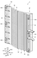
- FIG. 1 is an exploded perspective view showing a substrate storage container 1 according to an embodiment of the present invention.
- FIG. 2B is a front view of FIG. 2A.
- FIG. 2B is a right side view of FIG. 2A. This is a cross-sectional view taken along the line A1-A2-A3-A4 shown in Figure 2C.
- FIG. 3B is a partially enlarged view of FIG. 3A.
- 2B is a perspective cross-sectional view showing the container body 2 in a state in which a first side wall 25 is removed from the state shown in FIG. 2A.
- FIG. 2D is a right side view showing the container body 2 with the first side wall 25 removed from FIG. 2C.
- FIG. 13 is a left side view of the lateral substrate support portion 5 on the left side D31.
- FIG. 1 is an exploded perspective view showing a substrate storage container 1 according to an embodiment of the present invention.
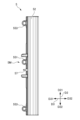
- FIG. 2A is an oblique cross-sectional view showing the configuration around the side substrate support portion 5 on the left side D31.
- FIG. 2B is a front view of FIG. 2A.
- FIG. 2C is a right side view of FIG. 2A.
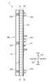
- FIG. 3A is a cross-sectional view along the line A1-A2-A3-A4 shown in FIG. 2C.
- FIG. 3B is a partially enlarged view of FIG. 3A.
- FIG. 4A is an oblique cross-sectional view showing the container body 2 in a state in which the first side wall 25 has been removed from FIG. 2A.
- FIG. 4B is a right side view showing the container body 2 in a state in which the first side wall 25 has been removed from FIG. 2C.
- FIG. 5A is an oblique view of the side substrate support portion 5 on the left side D31 as viewed from the upper left front side.
- FIG. 5B is a left side view of the side substrate support portion 5 on the left side D31.
- FIG. 5C is a front view of the side substrate support portion 5 on the left side D31.
- Figure 5D is a rear view of the lateral board support 5 on the left side D31.
- the direction from the container body 2 to the lid body 3 (lower left direction in FIG. 1) described below is defined as the front direction D11, and the opposite direction is defined as the rear direction D12, and these are defined as the front-rear direction D1.
- the direction from the lower wall 24 to the upper wall 23 described below is defined as the upper direction D21, and the opposite direction is defined as the lower direction D22, and these are defined as the up-down direction D2.
- the direction from the second side wall 26 to the first side wall 25 described below (upper left direction in FIG. 1) is defined as the left direction D31, and the opposite direction is defined as the right direction D32, and these are defined as the left-right direction D3 or the lateral direction D3.
- Direction may be called “side”.
- the inside of the lateral direction D3 means the side toward the center of the lateral direction D3, and for example, in the lateral substrate support part 5 or the first side wall 25 of the left side D31, it means the right direction or right side.
- the outside of the horizontal direction D3 means the side away from the center of the horizontal direction D3, for example, in the lateral substrate support 5 or first side wall 25 of the left side D31, it means the leftward or left side.
- the substrates W (shown by the two-dot chain line in FIG. 1) stored in the substrate storage container 1 are disk-shaped silicon wafers, glass wafers, sapphire wafers, etc., and are thin wafers used in industry.
- the substrates W are silicon wafers with a diameter of 450 mm.
- the substrate storage container 1 has a container body 2, a lid 3, and a side substrate support portion 5.
- the container body 2 has a container body opening 21 formed at one end on the front side D11 and a cylindrical wall portion 20 with the other end on the rear side D12 closed.
- a substrate storage space 27 is formed within the container body 2.
- the substrate storage space 27 is surrounded by the wall portion 20.
- a lateral substrate support portion 5 is disposed in the portion of the wall portion 20 that forms the substrate storage space 27.
- a plurality of substrates W can be stored in the substrate storage space 27.
- the side substrate support parts 5 are provided on the wall part 20 in pairs in the left-right direction D3 within the substrate storage space 27. When the container body opening 21 is not closed by the lid body 3, the side substrate support parts 5 can support the edges of multiple substrates W with adjacent substrates W arranged in parallel and spaced a predetermined distance from each other.
- a rear substrate support part 6 is provided at the rear side of the substrate storage space 27. The rear substrate support part 6 can support the rear edges of multiple substrates W when the container body opening 21 is closed by the lid body 3.
- the lid body 3 is detachable from the container body opening 21 and is capable of closing the container body opening 21.
- a front retainer (not shown) is provided on the portion of the lid body 3 that faces the substrate storage space 27 when the container body opening 21 is closed by the lid body 3 (the rear surface of the lid body 3 shown in FIG. 1).
- the front retainer (not shown) is arranged to form a pair with the rear substrate support portion 6.
- the front retainer (not shown) can support the front edges of multiple substrates W when the container body opening 21 is closed by the lid 3.
- the front retainer (not shown) cooperates with the rear substrate support portion 6 to support multiple substrates W, thereby holding the multiple substrates W in a state in which adjacent substrates W are spaced apart at a predetermined distance and arranged side by side.
- the wall portion 20 of the container body 2 has a back wall 22, an upper wall 23, a lower wall 24, a first side wall 25 (left wall), and a second side wall 26 (right wall).
- the back wall 22, the upper wall 23, the lower wall 24, the first side wall 25, and the second side wall 26 are made of a plastic material or the like, and in this embodiment, are integrally molded from polycarbonate.
- the first side wall 25 and the second side wall 26 face each other in the left-right direction D3, and the upper wall 23 and the lower wall 24 face each other in the up-down direction D2.
- the rear end of the upper wall 23, the rear end of the lower wall 24, the rear end of the first side wall 25, and the rear end of the second side wall 26 are all connected to the rear wall 22.
- the front end of the upper wall 23, the front end of the lower wall 24, the front end of the first side wall 25, and the front end of the second side wall 26 are positioned opposite the rear wall 22, and constitute an opening periphery 28 that forms the container body opening 21, which is approximately rectangular in shape.
- the opening periphery 28 is provided at one end of the container body 2, and the rear wall 22 is located at the other end of the container body 2.
- the outer shape of the container body 2 formed by the outer surfaces of the walls 20 is box-shaped.
- the inner surfaces of the walls 20, i.e., the inner surfaces of the rear wall 22, the inner surface of the upper wall 23, the inner surface of the lower wall 24, the inner surface of the first side wall 25, and the inner surface of the second side wall 26, form a substrate storage space 27 surrounded by these.
- the container body opening 21 formed at the opening periphery 28 is surrounded by the walls 20 and communicates with the substrate storage space 27 formed inside the container body 2.
- a maximum of 25 substrates W can be stored in the substrate storage space 27 with the upper and lower surfaces of the substrates W positioned approximately horizontally.
- the upper wall 23 and the lower wall 24 have latch engagement recesses 231A, 231B, 241A, and 241B recessed outward in the vertical direction D2 in the areas near the opening periphery 28.
- a total of four latch engagement recesses 231A, 231B, 241A, and 241B are formed, one near each of the left and right ends of the upper wall 23 and the lower wall 24.
- a flange fixing portion (not shown) is provided on the outer surface of the upper wall 23, integrally molded with the upper wall 23.
- the flange fixing portion (not shown) is disposed in the center of the upper wall 23.
- a top flange 236 is fixed to the flange fixing portion (not shown).
- the top flange 236 is disposed in the center of the upper wall 23.
- the first side wall 25 has a symmetrical shape with the second side wall 26, and the lateral board support portion 5 on the left side D31 has a symmetrical shape with the lateral board support portion 5 on the right side D32. Therefore, the following description will focus on the first side wall 25 and the lateral board support portion 5 on the left side D31, and for the second side wall 26 and the lateral board support portion 5 on the right side D32, the description of the first side wall 25 and the lateral board support portion 5 on the left side D31 will be used with the left and right reversed, and the description will be omitted or simplified.
- the lateral board support parts 5 are provided on the first side wall 25 and the second side wall 26, respectively, and are arranged in pairs in the left-right direction D3 within the board storage space 27. Specifically, as shown in Figures 5A to 5D, the lateral board support parts 5 have a plate part 51 and a plate part support part 52.
- the plate portion 51 and the plate support portion 52 are formed by integrally molding resin, so that the plate portion 51 is supported by the plate support portion 52.
- the plate portion 51 has a plate-like, generally arc shape. 25 plate portions 51 are provided on each of the first side wall 25 and the second side wall 26 in the vertical direction D2, for a total of 50 plate portions. Adjacent plate portions 51 are spaced apart from each other in the vertical direction D2 at intervals of 10 mm to 12 mm and are positioned in a parallel relationship. Note that above the uppermost plate portion 51, another plate-like member 59 is arranged parallel to the plate portion 51. Member 59 is a member that acts as a guide for the uppermost substrate W to be inserted into the substrate storage space 27.
- the 25 plate portions 51 provided on the first side wall 25 and the 25 plate portions 51 provided on the second side wall 26 are positioned opposite each other in the left-right direction D3.
- the 50 plate portions 51 and the plate-like guide members 59 parallel to the plate portions 51 are positioned parallel to the inner surface of the bottom wall 24.
- the plate support portion 52 is a plate-shaped portion extending in the up-down direction D2.
- a plurality of plate support portions 52 are provided at intervals in the front-rear direction D1.
- the plate support portions 52 are connected to the outer side edges of the plurality (all) of plate portions 51 in the lateral direction D3.
- the 25 plate portions 51 on the left side D31 are connected to the plate portion support portion 52 on the left side D31.
- the 25 plate portions 51 on the right side D32 are connected to the plate portion support portion 52 on the right side D32.
- the plate portion support portions 52 are fixed to the first side wall 25 and the second side wall 26, respectively.
- the inner surface of the first side wall 25 is partially formed in a stepped shape in the up-down direction D2 in two steps from the opening periphery 28 toward the rear direction D12 so that the distance between the first side wall 25 and the second side wall 26 in the left-right direction D3 becomes smaller.
- the portion forming the first step from the opening periphery 28 is called the first step 2541
- the portion forming the second step is called the second step 2542.
- the second step 2542 is disposed inside the first step 2541 in the left-right direction D3.
- Three first steps 2541 are arranged at a distance from each other in the up-down direction D2, and three second steps 2542 are arranged at a distance from each other.
- the first step 2541 is located within one-third, preferably one-quarter, of the range of the front side D11 of the first side wall 25.
- the second step 2542 is located within one-third, preferably one-quarter, of the range of the rear side D12 of the first side wall 25.
- the lateral board support portion 5 has a front first positioning portion 551 on the front side D11 and a rear first positioning portion 561 on the rear side D12.
- the first side wall 25 has a front second positioning portion 2552 on the front side D11 and a rear second positioning portion 2562 on the rear side D12.
- the front first positioning portion 551 and the front second positioning portion 2552 work together to position the front portion 5F of the lateral board support portion 5 of the left side D31 relative to the first side wall 25 in the vertical direction D2 and the horizontal direction D3 only in the central region 5M in the vertical direction D2 of the lateral board support portion 5 of the left side D31.
- the rear first positioning portion 561 and the rear second positioning portion 2562 work together to position the rear portion 5G of the lateral board support portion 5 of the left side D31 relative to the first side wall 25 in the vertical direction D2 and the horizontal direction D3 only in the central region 5M in the vertical direction D2 of the lateral board support portion 5 of the left side D31.
- the central region 5M in the vertical direction D2 of the lateral board support portion 5 is within a range of 15 mm above and below the center line of the lateral board support portion 5 in the vertical direction D2.
- the front first positioning portion 551 and the front second positioning portion 2552 and the rear first positioning portion 561 and the rear second positioning portion 2562 may be the same or different in position in the up-down direction D2 and the left-right direction D3.
- the rear first positioning portion 561 and the rear second positioning portion 2562 are positioned on the lower side D22, for example, 5 to 15 mm lower, relative to the front first positioning portion 551 and the front second positioning portion 2552.
- the A1-A2-A3-A4 cutting line shown in Figure 2C and the B1-B2-B3-B4 cutting line shown in Figure 5B are cutting lines at the same position.
- the rear first positioning portion 561 and the rear second positioning portion 2562 are positioned on the inside in the lateral direction D3 relative to the front first positioning portion 551 and the front second positioning portion 2552, for example, 25 to 35 mm inside.
- the lateral board support portion 5 has a front third positioning portion 553 on the front side D11, separate from the front first positioning portion 551.
- the first side wall 25 has a front fourth positioning portion 2554 separate from the front second positioning portion 2552.
- the lateral board support portion 5 has a rear third positioning portion 563 on the rear side D12, separate from the rear first positioning portion 561.
- the first side wall 25 has a rear fourth positioning portion 2564 separate from the rear second positioning portion 2562.
- the front third positioning portion 553 and the front fourth positioning portion 2554 work together to position the front portion 5F of the lateral board support portion 5 on the left side D31 in the left-right direction D3 relative to the first sidewall 25.
- the rear third positioning portion 563 and the rear fourth positioning portion 2564 work together to position the rear portion 5G of the lateral board support portion 5 on the left side D31 in the left-right direction D3 relative to the first sidewall 25.
- the front first positioning part 551 is provided on the front side D11 outside the lateral direction D3 of the lateral board support part 5, towards the center in the up-down direction D2.
- the front first positioning part 551 has an insertion hole into which the front second positioning part 2552 is inserted and fitted.
- the insertion hole of the front first positioning part 551 is a through hole that penetrates in the front-to-rear direction D1.
- the front second positioning portion 2552 is provided in the first step portion 2541 near the center in the up-down direction D2 on the front side D11 of the first side wall 25.
- the front second positioning portion 2552 is composed of a protrusion that protrudes in the front direction D11.
- the cross-sectional shape of the protrusion is, for example, a circle, a polygon, an L-shape, a U-shape, or may be a circle or polygon with a hollowed-out portion (the same applies below).
- the front third positioning part 553 is provided on the upper side D21 and the lower side D22 on the front side D11 outside the lateral direction D3 of the lateral board support part 5.
- the front third positioning part 553 has an insertion hole into which the front fourth positioning part 2554 is inserted and fitted.
- the insertion hole of the front third positioning part 553 is a through hole that penetrates in the front-to-rear direction D1.
- the front fourth positioning portion 2554 is provided in the first step portion 2541 of each of the upper side D21 and the lower side D22 on the front side D11 of the first side wall 25.
- the front fourth positioning portion 2554 is composed of a protrusion that protrudes in the forward direction D11.
- the rear first positioning part 561 is provided on the rear side D12, outside the lateral board support part 5 in the lateral direction D3, towards the center in the vertical direction D2.
- the rear first positioning part 561 has an insertion hole into which the rear second positioning part 2562 is inserted and fitted.
- the insertion hole of the rear first positioning part 561 is a through hole that penetrates in the front-to-rear direction D1.
- the rear second positioning portion 2562 is provided in the second step portion 2542 that is closer to the center in the up-down direction D2 on the rear side D12 of the first side wall 25.
- the rear second positioning portion 2562 is composed of a protruding portion that protrudes in the forward direction D11.
- the rear third positioning part 563 is provided on each of the upper side D21 and lower side D22 on the rear side D12 outside the lateral direction D3 of the lateral board support part 5.
- the rear third positioning part 563 has an insertion hole into which the rear fourth positioning part 2564 is inserted and fitted.
- the insertion hole of the rear third positioning part 563 is a through hole that penetrates in the front-to-rear direction D1.
- the rear fourth positioning portion 2564 is provided in the second step portion 2542 of each of the upper side D21 and the lower side D22 on the rear side D12 of the first side wall 25.
- the rear fourth positioning portion 2564 is composed of a protruding portion that protrudes in the forward direction D11.
- the positioning of the first positioning portion (front first positioning portion 551, rear first positioning portion 561) and the second positioning portion (front second positioning portion 2552, rear second positioning portion 2562) will be described using the configuration of the front side D11 as an example.
- the shape of the through hole of the front first positioning portion 551 is such that the front second positioning portion 2552 is inserted and fitted in the front-to-rear direction D1.
- the front second positioning portion 2552 is inserted and fitted into the through hole of the front first positioning portion 551
- the movement of the lateral board support portion 5 of the left side D31 in the up-down direction D2 and left-right direction D3 is restricted (constrained) on the front side D11 of the first side wall 25 (of the left side D31).
- the configuration of the rear side D12 is similar.
- the positioning of the third positioning portion (front third positioning portion 553, rear third positioning portion 563) and the fourth positioning portion (front fourth positioning portion 2554, rear fourth positioning portion 2564) will be explained using the configuration of the front side D11 as an example.
- the shape of the through hole of the front third positioning portion 553 is such that the front fourth positioning portion 2554 is inserted and fitted in the front-to-rear direction D1.
- the front fourth positioning portion 2554 is inserted and fitted into the through hole of the front third positioning portion 553, at the rear side D12 of the first side wall 25 (of the left side D31)
- the movement of the lateral board support portion 5 of the left side D31 in the left-right direction D3 is restricted (constrained) while movement in the up-down direction D2 is permitted (not restricted).
- the configuration that allows movement in the up-down direction D2 is achieved, for example, by having the through-hole of the front third positioning portion 553 have an elongated hole shape that extends in the up-down direction D2.
- the rear side D12 has
- the reason why movement of the lateral board support parts 5 in the vertical direction D2 is restricted by the first positioning part but not by the third positioning part is as follows. If movement in the vertical direction D2 is restricted at multiple points in the vertical direction D2 (first positioning part, third positioning part), misalignment of the positional relationships of the various parts can cause distortion or deformation in the vertical direction in the lateral board support parts 5. In contrast, if movement in the vertical direction D2 is restricted at only one point in the vertical direction D2, the aforementioned distortion or deformation will not occur.
- the lateral board support portion 5 on the left side D31 abuts against the first step portion 2541 of the first side wall 25 at the front first positioning portion 551 and the front third positioning portion 553, and abuts against the second step portion 2542 of the first side wall 25 at the rear first positioning portion 561 and the rear third positioning portion 563, thereby restricting movement in the rear direction D12.
- the first engagement part 57 is provided on the front side D11 outside the lateral direction D3 of the side board support part 5, toward the center in the up-down direction D2 (near the front first positioning part 551).
- the first engagement part 57 has a shape that can engage with the second engagement part 257 described below.
- the second engagement portion 257 is provided on the first step portion 2541 near the center in the up-down direction D2 on the front side D11 of the first side wall 25, together with the front second positioning portion 2552.
- the second engagement portion 257 has a shape that can engage with the first engagement portion 57.
- the first positioning portion (front first positioning portion 551, rear first positioning portion 561) and the second positioning portion (front second positioning portion 2552, rear second positioning portion 2562) are positioned, and a state is formed in which the third positioning portion (front third positioning portion 553, rear third positioning portion 563) and the fourth positioning portion (front fourth positioning portion 2554, rear fourth positioning portion 2564) are positioned, and the first engaging portion 57 and the second engaging portion 257 can be engaged. Due to this engagement, even if the first engaging portion 57 attempts to move in the forward direction D11, it abuts against the claw portion of the second engaging portion 257, thereby restricting (restraining) movement in the forward direction D11.
- the lateral board support portion 5 on the left side D31 abuts against the first step portion 2541 of the first side wall 25 at the front first positioning portion 551 and the front third positioning portion 553, and abuts against the second step portion 2542 of the first side wall 25 at the rear first positioning portion 561 and the rear third positioning portion 563, thereby restricting movement in the rear direction D12.
- movement in the up-down direction D2 and the left-right direction D3 is restricted by positioning of at least the first positioning portion (front first positioning portion 551, rear first positioning portion 561) and the second positioning portion (front second positioning portion 2552, rear second positioning portion 2562), movement in the rear direction D12 is restricted by the abutment of the front first positioning portion 551 and the front third positioning portion 553 with the first step portion 2541, and the abutment of the rear first positioning portion 561 and the rear third positioning portion 563 with the second step portion 2542, and movement in the front direction D11 is restricted by the engagement of the first engagement portion 57 with the second engagement portion 257.
- movement of the lateral board support portion 5 in six directions, front-rear, up-down, left-right, is restricted (positioned).
- the front first positioning portion 551 is located on the front side D11 of the plate portion 51. More specifically, the front first positioning portion 551 is provided on the plate portion support portion 52 which is located on the front side D11 of the plate portion 51.
- the rear first positioning portion 561 is located on the rear side D12 of the plate portion 51. More specifically, the rear first positioning portion 561 is provided on the plate portion support portion 52 which is located on the rear side D12 of the plate portion 51.
- the lateral substrate support portion 5 configured as described above is fixed to the first side wall 25 and the second side wall 26, the lateral substrate support portion 5 can support the edges of the multiple substrates W, with adjacent substrates W among the multiple substrates W spaced apart at a predetermined distance and positioned parallel to each other.
- the rear board support portion 6 is molded integrally with the plate portion 51 and the plate portion support portion 52 at the rear end of the plate portion 51 of the side board support portion 5 and the rear end of the plate portion support portion 52 at the rearmost side D12.
- the rear board support portion 6 may be configured separately from the plate portion 51 and the plate portion support portion 52 of the side board support portion 5, or may be configured (integrally) from a part of the wall portion 20 of the container body 2.
- the number of rear substrate support parts 6 is provided to correspond to each substrate W that can be stored in the substrate storage space 27, specifically 25.
- the rear substrate support parts 6 are positioned in the front-to-rear direction D1 so as to form a pair with a front retainer (not shown) fixed to the lid 3.
- a front retainer not shown
- the lid 3 has a generally rectangular shape that generally matches the shape of the opening rim 28 of the container body 2.
- the lid 3 is detachable from the opening rim 28 of the container body 2, and the lid 3 can close the container body opening 21 by attaching the lid 3 to the opening rim 28.
- An annular seal member 4 is attached to the inner surface of the lid 3 (the back surface of the lid 3 shown in FIG. 1) that faces the surface (seal surface 281) of the step formed immediately behind the opening rim 28 D12 when the lid 3 closes the container body opening 21.
- the seal member 4 is made of elastically deformable POE (polyoxyethylene), PEE, various thermoplastic elastomers such as polyester and polyolefin, fluororubber, silicone rubber, etc.
- the seal member 4 is arranged to go around the outer periphery of the lid 3.
- the seal member 4 When the lid 3 is attached to the opening periphery 28, the seal member 4 is sandwiched between the sealing surface 281 and the inner surface of the lid 3 and elastically deforms, so that the lid 3 closes the container body opening 21 in a sealed state.
- the substrate W By removing the lid 3 from the opening periphery 28, the substrate W can be inserted and removed from the substrate storage space 27 inside the container body 2.
- the lid body 3 is provided with a latch mechanism.
- the latch mechanism is provided near both the left and right ends of the lid body 3, and as shown in FIG. 1, includes two upper latch portions 32A that can protrude in an upward direction D21 from the top edge of the lid body 3, and two lower latch portions 32B that can protrude in a downward direction D22 from the bottom edge of the lid body 3.
- the two upper latch portions 32A are located near both the left and right ends of the top edge of the lid body 3, and the two lower latch portions 32B are located near both the left and right ends of the bottom edge of the lid body 3.
- An operating portion 33 is provided on the outer surface of the lid body 3.
- the upper latch portion 32A and the lower latch portion 32B can be made to protrude from the upper and lower edges of the lid body 3, or can be made not to protrude from the upper and lower edges.
- the upper latch portion 32A protrudes in the upward direction D21 from the upper edge of the lid body 3 and engages with the latch engagement recesses 231A, 231B of the container body 2
- the lower latch portion 32B protrudes in the downward direction D22 from the lower edge of the lid body 3 and engages with the latch engagement recesses 241A, 241B of the container body 2, thereby fixing the lid body 3 to the opening periphery 28 of the container body 2.
- a recess (not shown) is formed on the inside of the lid body 3, recessed toward the outside of the board storage space 27.
- a front retainer (not shown) is fixed to the recess (not shown) and to the part of the lid body 3 outside the recess.
- the front retainer has a front retainer board receiving portion (not shown).
- the front retainer board receiving portions are arranged in pairs, two at a predetermined distance apart in the left-right direction D3.
- the front retainer board receiving portions arranged in pairs in this manner are provided in 25 pairs parallel to each other in the up-down direction D2.
- the lateral substrate support parts 5 are attached to and detached from the first side wall 25 as follows.
- the following movements of the lateral substrate support parts 5 are performed sequentially or simultaneously.
- the rear first positioning part 561 is moved in the rear direction D12 and is extrapolated onto the rear second positioning part 2562 so as to form a state in which the rear first positioning part 561 and the rear second positioning part 2562 are positioned.
- the rear third positioning part 563 is extrapolated onto the rear fourth positioning part 2564 so as to form a state in which the rear third positioning part 563 and the rear fourth positioning part 2564 are positioned.
- the front first positioning portion 551 is extrapolated onto the front second positioning portion 2552 so as to form a state in which the front first positioning portion 551 and the front second positioning portion 2552 are positioned.
- the front third positioning portion 553 is moved in the rear direction D12 and extrapolated onto the front fourth positioning portion 2554 so as to form a state in which the front third positioning portion 553 and the front fourth positioning portion 2554 are positioned.
- the rear first positioning portion 561 and the rear third positioning portion 563 are abutted against the second step portion 2542, and the front first positioning portion 551 and the front third positioning portion 553 are abutted against the first step portion 2541.
- the first engagement portion 57 is moved outward in the lateral direction D3 to engage with the second engagement portion 257. This creates a state in which movement of the side board support portion 5 in six directions, front to back, up to down, left to right, is restricted (positioned).
- the engagement between the first engagement part 57 and the second engagement part 257 is released, and then the lateral board support part 5 is moved in the forward direction D11, whereby the lateral board support part 5 can be removed from the first side wall 25.
- the substrate storage container 1 of this embodiment has a substrate storage space 27 formed therein capable of storing a plurality of substrates W, a container body 2 having an opening periphery 28 at one end of the front side D11 where a container body opening 21 communicating with the substrate storage space 27 is formed, and the other end of the rear side D12 is closed.
- the container body 2 has opposing upper and lower walls 23 and 24, a pair of opposing left and right side walls 25 and 26, and a rear wall 22 to which the rear end of the upper wall 23, the rear end of the lower wall 24, and the rear ends of the pair of side walls 25 and 26 are connected, a lid body 3 that is detachable from the container body opening 21 and capable of closing the container body opening 21, and side substrate support parts 5 that are fixed to the pair of side walls 25 and 26 in a pair within the substrate storage space 27 and are capable of supporting the edges of the plurality of substrates W in a state in which adjacent substrates W among the plurality of substrates W are arranged in parallel with a predetermined distance between them when the container body opening 21 is not closed by the lid body 3.
- the lateral board support portion 5 has a first positioning portion (front first positioning portion 551, rear first positioning portion 561) on the lateral board support portion 5, and the side wall (first side wall 25, second side wall 26) has a second positioning portion (front second positioning portion 2552, rear second positioning portion 2562), and the first positioning portions (551, 561) and the second positioning portions (2552, 2562) work together to position the front 5F and/or rear 5G of the lateral board support portion 5 relative to the side wall (first side wall 25, second side wall 26) in the up-down direction D2 and left-right direction D3 only in the central region 5M of the lateral board support portion 5 in the up-down direction D2.
- the front 5F and/or rear 5G of the lateral substrate support portion 5 is positioned in the vertical direction D2 and the horizontal direction D3 only in the central region 5M of the lateral substrate support portion 5 in the vertical direction D2 relative to the side walls (first side wall 25, second side wall 26). Therefore, even if the region in the vertical direction D2 of the lateral substrate support portion 5 is farthest from the central region 5M, which is the reference position for positioning, it is about half the length of the lateral substrate support portion 5 in the vertical direction D2. In other words, it is possible to minimize the decrease in positioning accuracy caused by a large distance from the reference position for positioning. Therefore, it is possible to further improve the positioning accuracy of the lateral substrate support portion 5 relative to the side walls (first side wall 25, second side wall 26) of the container body 2.
- the lateral board support portion 5 has a third positioning portion (front third positioning portion 553, rear third positioning portion 563) in addition to the first positioning portion (front first positioning portion 551, rear first positioning portion 561), and the side wall (first side wall 25, second side wall 26) has a fourth positioning portion (front fourth positioning portion 2554, rear fourth positioning portion 2564) in addition to the second positioning portion (front second positioning portion 2552, rear second positioning portion 2562).
- the third positioning portions (553, 563) and the fourth positioning portions (2554, 2564) work together to position the front 5F and/or rear 5G of the lateral board support portion 5 relative to the side wall (first side wall 25, second side wall 26) in the left-right direction D3. Therefore, according to this embodiment, the positioning accuracy of the entire side board support part 5 in the left-right direction D3 can be further improved.
- the side substrate support portion 5 has a plurality of plate portions 51 that support the edges of a plurality of substrates W in a parallel positional relationship, and a plate portion support portion 52 that supports the plate portions 51 and is fixed to the side walls (first side wall 25, second side wall 26).
- the first positioning portion (front first positioning portion 551) is located on the front side D11 of the plate portion 51. Therefore, according to this embodiment, since the first positioning portion (front first positioning portion 551) can support the side end portion of the front side D11 of the plate portion 51, the side substrate support portion 5 is precisely fixed (corrected) and maintained by the side walls (first side wall 25, second side wall 26). In addition, the first positioning portion (front first positioning portion 551) can be used as a guide for alignment when engaging the container body 2 and the side substrate support portion 5.
- the present invention is not limited to the above-described embodiment, and modifications are possible within the technical scope described in the claims.
- the shape and configuration of the substrate storage container 1 are not limited to the shape and configuration of the above-described embodiment.
- a front first positioning portion 551 and a front second positioning portion 2552 are provided on the front side D11, and a rear first positioning portion 561 and a rear second positioning portion 2562 are provided on the rear side D12, but this is not limited to the above.
- a configuration in which the rear first positioning portion 561 and the rear second positioning portion 2562 are provided on the rear side D12, but the front first positioning portion 551 and the front second positioning portion 2552 are not provided on the front side D11 may also be used.
- the configuration of the first positioning portion (front first positioning portion 551, rear first positioning portion 561) and the second positioning portion (front second positioning portion 2552, rear second positioning portion 2562) is not limited as long as they can be positioned in the vertical direction D2 and the left-right direction D3 in cooperation with each other. Furthermore, the configuration of the third positioning portion (front third positioning portion 553, rear third positioning portion 563) and the fourth positioning portion (front fourth positioning portion 2554, rear fourth positioning portion 2564) is not limited as long as they can be positioned in the left-right direction D3 in cooperation with each other.
- the configuration of the first positioning portion, the second positioning portion, the third positioning portion, and the fourth positioning portion may be, for example, a protruding portion (such as a pin), a through hole, a bottomed hole, an open (open) receiving portion (such as a V-shaped notch, a U-shaped notch, etc.), or fastened by a screw.
- Their cross-sectional shape may be a circle, a polygon (such as a square), an L-shape, or a U-shape.
- Substrate storage container 2 Container body 20 Wall portion 21 Container body opening 22 Back wall 23 Upper wall 24 Lower wall 25 First side wall (side wall) 2541: First step portion 2542: Second step portion 2552: Front second positioning portion (second positioning portion) 2554 Front fourth positioning part (fourth positioning part) 2562 Rear second positioning part (second positioning part) 2564 Rear fourth positioning part (fourth positioning part) 257 Second engagement portion 26 Second side wall (side wall) 27 Substrate storage space 28 Opening periphery 281 Sealing surface 3 Lid 4 Sealing member 5 Side substrate support portion 51 Plate portion 52 Plate portion support portion 551 Front side first positioning portion (first positioning portion) 553 Front third positioning portion (third positioning portion) 561 Rear first positioning portion (first positioning portion) 563 Rear third positioning portion (third positioning portion) 57 First engagement portion 5F Front portion 5G Rear portion 5M Central region 6 Back side board support portion D1 Front-rear direction D11 Front side, front direction D12 Rear side, rear direction D2 Up-down direction D21 Upper side, upper direction D22 Lower
Landscapes
- Packaging Frangible Articles (AREA)
- Container, Conveyance, Adherence, Positioning, Of Wafer (AREA)
Priority Applications (5)
| Application Number | Priority Date | Filing Date | Title |
|---|---|---|---|
| PCT/JP2023/020688 WO2024247263A1 (ja) | 2023-06-02 | 2023-06-02 | 基板収納容器 |
| JP2025523203A JPWO2024247263A1 (https=) | 2023-06-02 | 2023-06-02 | |
| KR1020257040056A KR20260018834A (ko) | 2023-06-02 | 2023-06-02 | 기판수납용기 |
| CN202380097566.8A CN121002638A (zh) | 2023-06-02 | 2023-06-02 | 基板收纳容器 |
| TW113119219A TW202448779A (zh) | 2023-06-02 | 2024-05-24 | 基板收納容器 |
Applications Claiming Priority (1)
| Application Number | Priority Date | Filing Date | Title |
|---|---|---|---|
| PCT/JP2023/020688 WO2024247263A1 (ja) | 2023-06-02 | 2023-06-02 | 基板収納容器 |
Publications (1)
| Publication Number | Publication Date |
|---|---|
| WO2024247263A1 true WO2024247263A1 (ja) | 2024-12-05 |
Family
ID=93657524
Family Applications (1)
| Application Number | Title | Priority Date | Filing Date |
|---|---|---|---|
| PCT/JP2023/020688 Ceased WO2024247263A1 (ja) | 2023-06-02 | 2023-06-02 | 基板収納容器 |
Country Status (5)
| Country | Link |
|---|---|
| JP (1) | JPWO2024247263A1 (https=) |
| KR (1) | KR20260018834A (https=) |
| CN (1) | CN121002638A (https=) |
| TW (1) | TW202448779A (https=) |
| WO (1) | WO2024247263A1 (https=) |
Citations (3)
| Publication number | Priority date | Publication date | Assignee | Title |
|---|---|---|---|---|
| JP2012004199A (ja) * | 2010-06-15 | 2012-01-05 | Shin Etsu Polymer Co Ltd | 基板収納容器 |
| WO2014203359A1 (ja) * | 2013-06-19 | 2014-12-24 | ミライアル株式会社 | 基板収納容器 |
| WO2022208602A1 (ja) * | 2021-03-29 | 2022-10-06 | ミライアル株式会社 | 基板収納容器 |
-
2023
- 2023-06-02 KR KR1020257040056A patent/KR20260018834A/ko active Pending
- 2023-06-02 WO PCT/JP2023/020688 patent/WO2024247263A1/ja not_active Ceased
- 2023-06-02 JP JP2025523203A patent/JPWO2024247263A1/ja active Pending
- 2023-06-02 CN CN202380097566.8A patent/CN121002638A/zh active Pending
-
2024
- 2024-05-24 TW TW113119219A patent/TW202448779A/zh unknown
Patent Citations (3)
| Publication number | Priority date | Publication date | Assignee | Title |
|---|---|---|---|---|
| JP2012004199A (ja) * | 2010-06-15 | 2012-01-05 | Shin Etsu Polymer Co Ltd | 基板収納容器 |
| WO2014203359A1 (ja) * | 2013-06-19 | 2014-12-24 | ミライアル株式会社 | 基板収納容器 |
| WO2022208602A1 (ja) * | 2021-03-29 | 2022-10-06 | ミライアル株式会社 | 基板収納容器 |
Also Published As
| Publication number | Publication date |
|---|---|
| KR20260018834A (ko) | 2026-02-09 |
| TW202448779A (zh) | 2024-12-16 |
| JPWO2024247263A1 (https=) | 2024-12-05 |
| CN121002638A (zh) | 2025-11-21 |
Similar Documents
| Publication | Publication Date | Title |
|---|---|---|
| JP6177248B2 (ja) | 基板収納容器 | |
| JP7414982B2 (ja) | 基板収納容器 | |
| TWI796660B (zh) | 基板收納容器 | |
| CN102792435A (zh) | 基板收存容器 | |
| WO2018185894A1 (ja) | 基板収納容器 | |
| US9960064B2 (en) | Substrate storing container | |
| JP7562657B2 (ja) | 基板収納容器 | |
| WO2014196011A1 (ja) | 基板収納容器 | |
| JP6030758B2 (ja) | 基板収納容器 | |
| WO2024247263A1 (ja) | 基板収納容器 | |
| KR102930874B1 (ko) | 기판수납용기, 그 제조방법 및 뚜껑체측 기판지지부 | |
| KR102942671B1 (ko) | 기판수납용기 및 그 뚜껑 | |
| WO2024241560A1 (ja) | 基板収納容器 | |
| WO2025163816A1 (ja) | 基板収納容器 | |
| WO2024247264A1 (ja) | 基板収納容器 | |
| WO2024252672A1 (ja) | 基板収納容器 | |
| JP6000075B2 (ja) | 基板収納容器 | |
| JP7210835B2 (ja) | 薄板収納容器 | |
| JP2020009981A (ja) | 基板収納容器 | |
| WO2025109707A1 (ja) | 基板収納容器 | |
| TW202348529A (zh) | 基板收納容器以及蓋體側基板支承部 | |
| WO2024105879A1 (ja) | 収納容器及びアダプター部材 | |
| TW202516659A (zh) | 基板收納容器 | |
| WO2026083709A1 (ja) | 基板収納容器 | |
| WO2026047841A1 (ja) | 基板収納容器 |
Legal Events
| Date | Code | Title | Description |
|---|---|---|---|
| 121 | Ep: the epo has been informed by wipo that ep was designated in this application |
Ref document number: 23938710 Country of ref document: EP Kind code of ref document: A1 |
|
| ENP | Entry into the national phase |
Ref document number: 2025523203 Country of ref document: JP Kind code of ref document: A |
|
| WWE | Wipo information: entry into national phase |
Ref document number: 2025523203 Country of ref document: JP |
|
| NENP | Non-entry into the national phase |
Ref country code: DE |