WO2024247005A1 - 燃料電池 - Google Patents
燃料電池 Download PDFInfo
- Publication number
- WO2024247005A1 WO2024247005A1 PCT/JP2023/019771 JP2023019771W WO2024247005A1 WO 2024247005 A1 WO2024247005 A1 WO 2024247005A1 JP 2023019771 W JP2023019771 W JP 2023019771W WO 2024247005 A1 WO2024247005 A1 WO 2024247005A1
- Authority
- WO
- WIPO (PCT)
- Prior art keywords
- fuel cell
- conductive substrate
- gas
- porous support
- layer
- Prior art date
- Legal status (The legal status is an assumption and is not a legal conclusion. Google has not performed a legal analysis and makes no representation as to the accuracy of the status listed.)
- Ceased
Links
Images





Classifications
-
- H—ELECTRICITY
- H01—ELECTRIC ELEMENTS
- H01M—PROCESSES OR MEANS, e.g. BATTERIES, FOR THE DIRECT CONVERSION OF CHEMICAL ENERGY INTO ELECTRICAL ENERGY
- H01M8/00—Fuel cells; Manufacture thereof
- H01M8/02—Details
- H01M8/0202—Collectors; Separators, e.g. bipolar separators; Interconnectors
- H01M8/0258—Collectors; Separators, e.g. bipolar separators; Interconnectors characterised by the configuration of channels, e.g. by the flow field of the reactant or coolant
-
- H—ELECTRICITY
- H01—ELECTRIC ELEMENTS
- H01M—PROCESSES OR MEANS, e.g. BATTERIES, FOR THE DIRECT CONVERSION OF CHEMICAL ENERGY INTO ELECTRICAL ENERGY
- H01M8/00—Fuel cells; Manufacture thereof
- H01M8/02—Details
- H01M8/0202—Collectors; Separators, e.g. bipolar separators; Interconnectors
- H01M8/023—Porous and characterised by the material
-
- H—ELECTRICITY
- H01—ELECTRIC ELEMENTS
- H01M—PROCESSES OR MEANS, e.g. BATTERIES, FOR THE DIRECT CONVERSION OF CHEMICAL ENERGY INTO ELECTRICAL ENERGY
- H01M8/00—Fuel cells; Manufacture thereof
- H01M8/02—Details
- H01M8/0202—Collectors; Separators, e.g. bipolar separators; Interconnectors
- H01M8/0247—Collectors; Separators, e.g. bipolar separators; Interconnectors characterised by the form
-
- H—ELECTRICITY
- H01—ELECTRIC ELEMENTS
- H01M—PROCESSES OR MEANS, e.g. BATTERIES, FOR THE DIRECT CONVERSION OF CHEMICAL ENERGY INTO ELECTRICAL ENERGY
- H01M8/00—Fuel cells; Manufacture thereof
- H01M8/02—Details
- H01M8/0271—Sealing or supporting means around electrodes, matrices or membranes
-
- H—ELECTRICITY
- H01—ELECTRIC ELEMENTS
- H01M—PROCESSES OR MEANS, e.g. BATTERIES, FOR THE DIRECT CONVERSION OF CHEMICAL ENERGY INTO ELECTRICAL ENERGY
- H01M8/00—Fuel cells; Manufacture thereof
- H01M8/10—Fuel cells with solid electrolytes
- H01M8/12—Fuel cells with solid electrolytes operating at high temperature, e.g. with stabilised ZrO2 electrolyte
- H01M8/1213—Fuel cells with solid electrolytes operating at high temperature, e.g. with stabilised ZrO2 electrolyte characterised by the electrode/electrolyte combination or the supporting material
-
- H—ELECTRICITY
- H01—ELECTRIC ELEMENTS
- H01M—PROCESSES OR MEANS, e.g. BATTERIES, FOR THE DIRECT CONVERSION OF CHEMICAL ENERGY INTO ELECTRICAL ENERGY
- H01M8/00—Fuel cells; Manufacture thereof
- H01M8/10—Fuel cells with solid electrolytes
- H01M8/12—Fuel cells with solid electrolytes operating at high temperature, e.g. with stabilised ZrO2 electrolyte
- H01M8/124—Fuel cells with solid electrolytes operating at high temperature, e.g. with stabilised ZrO2 electrolyte characterised by the process of manufacturing or by the material of the electrolyte
- H01M8/1246—Fuel cells with solid electrolytes operating at high temperature, e.g. with stabilised ZrO2 electrolyte characterised by the process of manufacturing or by the material of the electrolyte the electrolyte consisting of oxides
- H01M8/1253—Fuel cells with solid electrolytes operating at high temperature, e.g. with stabilised ZrO2 electrolyte characterised by the process of manufacturing or by the material of the electrolyte the electrolyte consisting of oxides the electrolyte containing zirconium oxide
-
- H—ELECTRICITY
- H01—ELECTRIC ELEMENTS
- H01M—PROCESSES OR MEANS, e.g. BATTERIES, FOR THE DIRECT CONVERSION OF CHEMICAL ENERGY INTO ELECTRICAL ENERGY
- H01M8/00—Fuel cells; Manufacture thereof
- H01M8/10—Fuel cells with solid electrolytes
- H01M8/12—Fuel cells with solid electrolytes operating at high temperature, e.g. with stabilised ZrO2 electrolyte
- H01M2008/1293—Fuel cells with solid oxide electrolytes
-
- Y—GENERAL TAGGING OF NEW TECHNOLOGICAL DEVELOPMENTS; GENERAL TAGGING OF CROSS-SECTIONAL TECHNOLOGIES SPANNING OVER SEVERAL SECTIONS OF THE IPC; TECHNICAL SUBJECTS COVERED BY FORMER USPC CROSS-REFERENCE ART COLLECTIONS [XRACs] AND DIGESTS
- Y02—TECHNOLOGIES OR APPLICATIONS FOR MITIGATION OR ADAPTATION AGAINST CLIMATE CHANGE
- Y02E—REDUCTION OF GREENHOUSE GAS [GHG] EMISSIONS, RELATED TO ENERGY GENERATION, TRANSMISSION OR DISTRIBUTION
- Y02E60/00—Enabling technologies; Technologies with a potential or indirect contribution to GHG emissions mitigation
- Y02E60/30—Hydrogen technology
- Y02E60/50—Fuel cells
Definitions
- the present invention relates to a fuel cell.
- a fuel cell has a structure in which an electrolyte is sandwiched between two electrodes, an anode and a cathode, and generates electricity by supplying a fuel gas such as hydrogen to the anode side and a gas containing oxygen such as air to the cathode side.
- the fuel cell disclosed in Patent Document 1 is constructed by stacking an electrode layer/electrolyte layer/electrode layer in this order on a metal support frame.
- the metal support frame in Patent Document 1 is divided into a dense region and a porous region, and the porous region has through-holes with a diameter of 10 to 150 ⁇ m to supply gas to the electrode layer directly above.
- anodized alumina can have a through-hole diameter of 300 nm or less, and this can be used as a porous support layer on which an electrode layer/electrolyte layer/electrode layer can be stacked in this order to form a thin-film fuel cell.
- anodized alumina is an insulating material, it is conceivable to form a metal film on the inner wall of the through-hole to electrically connect the front and back, place it on a conductive substrate such as a metal support frame, and extract the generated electricity to the outside.
- the conductive substrate will block part of the through-holes in the porous support layer, reducing the effective area of the fuel cell.
- the metal support frame in Patent Document 1 has a maximum porosity of 60%, so if a thin-film cell using a porous support layer is placed on it, the effective area will be reduced by 40%.
- the present invention was made in consideration of the above problems, and aims to provide a fuel cell that can ensure the effective surface area of the fuel cell while suppressing the parasitic resistance of the fuel cell.
- the conductive substrate is arranged so as to contact the porous support layer in a location where no through-holes are formed, and a structure is formed at the boundary between the conductive substrate and the porous support layer in the location, which allows gas to flow in a direction perpendicular to the extension direction of the through-holes.
- the fuel cell according to the present invention can ensure the effective area of the fuel cell while suppressing the parasitic resistance of the fuel cell. Problems, configurations, and effects other than those described above will become clear from the description of the embodiment below.
- FIG. 1 is a cross-sectional view showing a structure of a fuel cell 1 according to a first embodiment.
- FIG. 2 is an enlarged cross-sectional view of the porous support layer 4.
- 2 is an enlarged perspective view of a surface of a conductive substrate 2.
- FIG. 3B is a further enlarged view of the vicinity of the surface flow channel 10 in FIG. 3A.
- FIG. FIG. 2 is a cross-sectional view showing a current path when the porous support layer 4 is made of an insulating material.
- 2 is a cross-sectional view showing an example of the structure of a fuel cell stack 500.
- FIG. FIG. 5 is an exploded view of the layers of a fuel cell stack 500.
- FIG. 6 is a cross-sectional view showing an example of the structure of a fuel cell stack 600 according to a second embodiment.
- 11 is a cross-sectional view showing an example of the structure of a fuel cell 1 according to a third embodiment.
- FIG. FIG. 11 is a cross-sectional view showing an example of the structure of a fuel cell 1 according to a fourth embodiment.
- FIG. 4 is a diagram for explaining the definition of the depth of the surface flow channel 10.
- FIG. 4 is a diagram for explaining the definition of the depth of the surface flow channel 10.
- FIG. 11 is a cross-sectional view showing an example of the structure of a fuel cell 1000 according to a fifth embodiment.
- 13 is a cross-sectional view showing a structural example of a fuel cell 1 according to a sixth embodiment.
- FIG. 13 is a cross-sectional view showing a structural example of a fuel cell 1 according to a seventh embodiment.
- FIG. 13 is a cross-sectional view showing a structural example of a fuel cell 1 according to an eighth embodiment.
- FIG. 13 is a cross-sectional view showing a structural example of a fuel cell 1 according to a ninth embodiment.
- FIG. 13 is a cross-sectional view showing a structural example of a fuel cell 1 according to a tenth embodiment.
- FIG. 23 is a cross-sectional view showing a structural example of a fuel cell 1 according to an eleventh embodiment.
- 23 is a cross-sectional view showing a structural example of a fuel cell 1 according to a thirteenth embodiment.
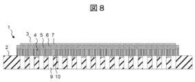
- ⁇ First embodiment> 1 is a cross-sectional view showing the structure of a fuel cell 1 according to embodiment 1 of the present invention.
- the fuel cell 1 has at least one unit cell 3 (hereinafter simply referred to as a cell) mounted on a conductive substrate 2.
- the unit cell 3 is a fuel cell composed of a porous support layer 4, a first electrode layer 5, an electrolyte layer 6 (solid electrolyte layer), and a second electrode layer 7, and the electrolyte layer 6 is sandwiched between the first electrode layer 5 and the second electrode layer 7.
- the porous support layer 4 plays a role in supporting the entire unit cell 3.
- the porous support layer 4 has a porous structure with second through holes 8 in the Z direction as shown in FIG. 2 described later, allowing gas to reach the first electrode layer 5.
- the Z direction is the direction from the bottom surface of the conductive substrate 2 to the surface of the second electrode layer 7.
- the plane with the Z direction as the normal direction is the XY plane, the direction perpendicular to the Z direction is the X direction, and the direction perpendicular to both the Z direction and the X direction is the Y direction.
- the first electrode layer 5 is formed by a film formation process such as sputtering, but rather than forming the first electrode layer 5 all over the porous support layer 4, an area is provided on the outer periphery of the porous support layer 4 where the first electrode layer 5 is not formed. This is because the first electrode layer 5 has a porous structure to supply gas to the electrolyte layer 6, and if the first electrode layer 5 is formed all over the porous support layer 4, there is a risk of gas leakage occurring between the top and bottom of the unit cell 3. Gas leakage can be prevented by leaving the outer periphery of the porous support layer 4 and covering it with the electrolyte layer 6, which has a dense structure.
- the first electrode layer 5 When the first electrode layer 5 functions as an anode of a fuel cell, a fuel gas such as hydrogen is supplied to the first electrode layer 5.
- the first electrode layer 5 is made of a material such as a cermet of nickel and yttria-stabilized zirconia.
- the electrolyte layer 6 is made of a material such as stabilized zirconia with an yttria composition ratio of 8%. If the electrolyte layer 6 is made into a thin film of 1 ⁇ m or less by a film formation process such as sputtering, it is also possible to obtain power generation with a high output density.
- the second electrode layer 7 is a cathode, and is made of a material such as platinum, a cermet of platinum and GDC (gadolinium doped ceria), or LSC ((La, Sr)CoO 3 ), and is made into a porous structure so that an oxidant gas reaches the electrolyte layer 6.
- the second electrode layer 7 does not necessarily have to have a porous structure as long as it is made of a material that has conductivity of both oxygen ions (O 2- ) and electrons.
- an oxidant gas is supplied to the first electrode layer 5 and a fuel gas is supplied to the second electrode layer 7 .
- the conductive substrate 2 is an electrical conductor, and is desirably made of a material such as a stainless steel alloy that has a certain level of mechanical strength even at high temperatures. In addition, it is desirably made of a material that has a thermal expansion coefficient close to that of the porous support layer 4. For example, when the porous support layer 4 is made of aluminum oxide, the conductive substrate 2 desirably has a thermal expansion coefficient of 10 ⁇ 10 ⁇ 6 /K (linear expansion coefficient) or less, and more ideally, about 7 to 8 ⁇ 10 ⁇ 6 /K (linear expansion coefficient).
- First through holes 9 are provided in the conductive substrate 2 by forming them using laser processing technology or the like. These first through holes 9 have a larger area than the second through holes 8 in the porous support layer 4, and can be 100 times larger or more. The distance between the first through holes 9 is also about the same as the width of the first through holes 9 in the conductive substrate, and can be 100 times larger or more than the width of the second through holes 8. Therefore, on the surface where the conductive substrate 2 and the porous support layer 4 contact each other, a large number of second through holes 8 in the porous support layer 4 are arranged between the first through holes 9 in the conductive substrate 2.
- the conductive substrate 2 has a surface flow path 10 (a structure that allows gas to flow in a direction perpendicular to the extension direction of the second through hole 8) on its surface.
- the detailed structure of the surface flow path 10 will be described later.
- the surface flow path 10 allows gas supplied from the first through hole 9 of the conductive substrate 2 to pass through the surface flow path 10 and be supplied to the second through hole 8 of the porous support layer 4, and further to the first electrode layer 5.
- the second through holes 8 are blocked in the areas where the conductive substrate 2 and porous support layer 4 contact each other and where the first through holes 9 are not formed. This means that gas does not flow through these areas, and the effective area of the surface area of the unit cell 3 that contributes to power generation is reduced.
- gas is supplied to the second through holes 8 even in positions where the first through holes 9 are not formed.
- no surface flow path 10 is provided at the end positions of the unit cell 3. This is to prevent the fuel gas and oxidant gas from mixing via the surface flow path 10.
- FIG. 2 is an enlarged cross-sectional view of the porous support layer 4.
- the porous support layer 4 has a plurality of second through holes 8 penetrating in the Z direction.
- the diameter of the second through holes 8 is preferably 300 nm or less. If the hole diameter is too large, the thickness of the layer formed above the second through holes 8 in order to block the second through holes 8 must be correspondingly large.
- FIG. 3A is an enlarged perspective view of the surface of the conductive substrate 2.
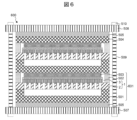
- FIG. 3B is a further enlarged view of the vicinity of the surface flow path 10. A part of the gas that reaches the surface of the conductive substrate 2 through the first through hole 9 enters the surface flow path 10 and proceeds in the X and Y directions. As shown in FIG. 3B, there is a porous support layer 4 directly above the conductive substrate 2, so the gas enters the second through hole 8 of the porous support layer 4 and proceeds in the Z direction toward the first electrode layer 5. Although only four gas paths are shown in FIG. 3A, in reality, the gas diffuses in all directions, branches in the X and Y directions along the way, and spreads over the entire surface of the conductive substrate 2.
- FIG. 4A is a cross-sectional view showing the current path.
- the first electrode layer 5 is used as an anode.
- the porous support layer 4 is a conductive material.
- the fuel gas passes through the first electrode layer 5, which has a porous structure, via the surface flow path 10 of the conductive substrate 2 and the second through hole 8 of the porous support layer 4, and at the interface with the electrolyte layer 6, reacts with oxygen ions that have moved through the electrolyte layer 6, generating water vapor and electrons.
- the water vapor is discharged to the outside via the second through hole 8, the surface flow path 10, and the first through hole 9 (not shown).
- the electrons are taken out from the first electrode layer 5 via the porous support layer 4 and the conductive substrate 2 and sent to a load that consumes power.
- FIG. 4B is a cross-sectional view showing the current path when the porous support layer 4 is made of an insulating material.
- the porous support layer 4 is made of an insulating material, an electrical connection from the front surface to the back surface of the porous support layer 4 is necessary, and this is achieved, for example, by providing an internal through-hole wiring 11 inside the second through-hole 8.
- the flow of gas and oxygen ions is the same as in FIG. 4A, but since the porous support layer 4 is made of an insulating material, electrons generated at the interface between the first electrode layer 5 and the electrolyte layer 6 flow toward the internal through-hole wiring 11 and are taken out to the outside via the internal through-hole wiring 11 and the conductive substrate 2. If the internal through-hole wiring 11 is formed so as to continue to the back surface of the porous support layer 4 as in FIG. 4B, an electrical connection between the internal through-hole wiring 11 and the conductive substrate 2 can be ensured.
- FIG. 5A is a cross-sectional view showing an example structure of a fuel cell stack 500.
- Fuel cell stack 500 is composed of fuel cell 1, separator 501, cell portion gasket 502, current collector 503, upper electrode plate 504, lower gasket 505, upper gasket 506, bottom jig 507, top jig 508, support 509, and fastening member 510.
- Fuel cell stack 500 is assembled by stacking, from the bottom, bottom jig 507, lower gasket 505, separator 501, fuel cell 1, upper electrode plate 504, upper gasket 506, and top jig 508 in that order.
- Holes are drilled in the bottom jig 507 and the top jig 508 to pass the support 509 through, and both ends of the support 509 are machined to match the shape of the fastening member 510.
- the fastening member 510 is a nut
- the support 509 is provided with a thread of the same shape as the fastening member 510, and the entire fuel cell stack 500 is fastened from above and below by fastening the fastening member 510.
- This structure prevents the fuel gas and oxidant gas used in the operation of the fuel cell 1 from leaking outside the fuel cell stack 500.
- the separator 501 and the conductive substrate 2 are joined by welding or the like to prevent gas from leaking outside and to electrically connect the separator 501 to the first electrode layer 5 of the fuel cell 1.
- the separator 501 is shaped so that it has a recess on the inside, leaving the ends, forming a gas flow path 511 that can supply gas to the first through-hole 9 of the conductive substrate 2.
- the upper electrode plate 504 is electrically connected to the second electrode layer 7 via the current collector 503, so that the electricity generated by the fuel cell 1 can be taken out to the outside.
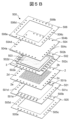
- FIG. 5B is an exploded view of each layer of the fuel cell stack 500.
- the conductive substrate 2 has a first gas inlet 2a, a first gas outlet 2b, a second gas inlet 2c, and a second gas outlet 2d.
- the first gas is a fuel gas or an oxidizer gas
- the second gas is an oxidizer gas when the first gas is a fuel gas, or is a fuel gas when the first gas is an oxidizer gas.
- the separator 501 has a first gas inlet 501a, a first gas outlet 501b, a second gas inlet 502c, and a second gas outlet 501d
- the cell portion gasket 502 has a first gas inlet 502a, a first gas outlet 502b, a second gas inlet 502c, and a second gas outlet 502d
- the upper electrode plate 504 has a first gas inlet 504a, a first gas outlet 504b, a second gas inlet 504c, and a second gas outlet 504d.
- the first gas and the second gas can be supplied to the unit cell 3 from the bottom jig 507 or the top jig 508. Gas can also be supplied from both the bottom jig 507 and the top jig 508.
- FIG. 5B a configuration example is shown in which all layers have inlets and outlets on four sides. As an example, a case will be described below in which the first gas is supplied from the first gas inlet 505a of the lower gasket and the second gas is supplied from the second gas inlet 506c of the upper gasket.
- the first gas supplied from the first gas inlet 505a of the lower gasket flows into the first gas inlet 501a of the separator. Since the first gas inlet 501a of the separator has a notch, the first gas passes over the separator 501 and heads toward the first gas outlet 501b. The location through which the first gas passes is the gas flow path 511 in FIG. 5A, and the first gas is supplied to the back surface of the unit cell 3 via the first through hole 9 of the conductive substrate 2. At this time, since the surface flow path 10 is formed on the surface of the conductive substrate 2 as shown in FIG. 3, the first gas is supplied to the second through hole 8 of the porous support layer 4 via the surface flow path 10, thereby suppressing loss of the power generation area. The first gas supplied to the second through hole 8 is supplied to the first electrode layer 5, and further, by making the first electrode layer 5 a porous structure, it is supplied to the interface between the first electrode layer 5 and the electrolyte layer 6.
- the first gas that reaches the first gas outlet 501b of the separator flows toward the first gas outlet 505b of the lower gasket and is discharged to the outside of the fuel cell stack 500 via the bottom fixture 507.
- the first gas flows upwards, passing through the first gas inlet 2a of the conductive substrate and the first gas inlet 502a of the cell gasket in that order.
- the second gas supplied from the second gas inlet 506c of the upper gasket flows into the second gas inlet 504c of the upper electrode plate 504.
- the second gas further travels to the second gas inlet 502c of the cell gasket. Since the second gas inlet 502c of the cell gasket has a notch, the second gas travels to the second gas outlet 502d of the cell gasket while passing over the unit cell 3 on the conductive substrate 2.
- There is a current collector 503 on the unit cell 3 and if the current collector 503 has a gas-permeable structure such as a mesh structure, the second gas can be supplied to the second electrode layer 7 on the surface of the unit cell 3.
- the second electrode layer 7 a porous structure, the second gas can be supplied up to the interface between the second electrode layer 7 and the electrolyte layer 6.
- the second gas that reaches the second gas outlet 501d of the cell gasket passes through the second gas outlet 504d of the upper electrode plate 504 toward the second gas outlet 506d of the upper gasket, and is discharged to the outside of the fuel cell stack 500 via the top surface jig 508.
- ⁇ Embodiment 2> 6 is a cross-sectional view showing an example of the structure of a fuel cell stack 600 according to a second embodiment of the present invention.
- the fuel cell stack 600 is composed of a unit stack 601, an upper electrode plate 504, a lower gasket 505, an upper gasket 506, a bottom jig 507, a top jig 508, supports 509, and fastening members 510.
- the unit stack 601 refers to the area composed of the fuel cell 1, the separator 501, the cell portion gasket 502, and the current collector 503.
- the structure of the fuel cell 1 is the same as that of the first embodiment.
- the unit stack 601 structure is stacked vertically. This allows two unit cells 3 to be connected in series, increasing the output voltage of the entire stack.
- the unit stacks 601 by repeatedly stacking the unit stacks 601, it is possible to connect three or more unit cells in series, and the output voltage of the entire stack increases depending on the number of stacks. Even when multiple stacks are stacked in this way, loss of power generation area can be reduced by providing a surface flow path 10 on the surface of the conductive substrate 2, as in embodiment 1.
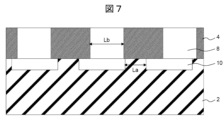
- ⁇ Third embodiment> 7 is a cross-sectional view showing an example of the structure of a fuel cell 1 according to embodiment 3 of the present invention.
- the XY coordinate positions of the second through-holes 8 in the porous support layer 4 and the surface flow paths 10 in the conductive substrate 2 coincide with each other.
- the dimensions of the second through-holes 8 and the surface flow paths 10 are on the order of several hundred nanometers, and it may be difficult to align their positions or repeat lengths.
- the width of the protrusions of the surface flow paths 10 (La in the figure) is made shorter than the width of the second through holes 8 of the porous support layer 4 (Lb in the figure), so that the second through holes 8 are not completely blocked. This makes it possible to prevent loss of power generation area.
- the rest of the configuration is the same as in the first embodiment.
- ⁇ Fourth embodiment> 8 is a cross-sectional view showing an example of the structure of a fuel cell 1 according to a fourth embodiment of the present invention.
- the surface flow path 10 of the conductive substrate 2 does not necessarily have to be rectangular, and can be, for example, an aggregate of fine particles.
- the other configurations are the same as those of the first embodiment.
- the material for these particles may be, for example, nickel.
- the surface flow path 10 can be formed from an aggregate of particles by a method such as making a paste using an organic solvent, applying it to the surface of the conductive substrate 2, and baking it.
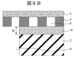
- FIGS. 9A and 9B are diagrams for explaining the definition of the depth of the surface flow path 10 in the present invention.
- FIG. 9A shows the case where the surface of the conductive substrate 2 is processed
- FIG. 9B shows the case where a layer of an aggregate of fine particles or the like is used as the surface flow path 10 as in embodiment 4.
- the depth of the surface flow path 10 is defined as the length corresponding to D shown by the arrow in the figure, that is, the length from the point closest to the porous support layer 4 to the bottom surface of the porous support layer 4 in the area of the conductive substrate 2 where there are no gas flow paths in the XY directions.
- the degree of processing difficulty is mainly determined by the aspect ratio D/W of the depth D and width W, and it is desirable for this aspect ratio to be in the range of 3 to 100.
- the depth of the surface flow path 10 required in the case of FIG. 9B depends on the porosity of the microparticle aggregate, etc. (the ratio of the volume of only the voids to the total volume including the voids).
- a low porosity affects gas diffusion, and a high porosity affects parasitic electrical resistance, so it is desirable to set the porosity to be in the range of 30 to 70%.
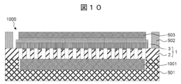
- ⁇ Fifth embodiment> 10 is a cross-sectional view showing a structural example of a fuel cell 1000 according to a fifth embodiment of the present invention.
- a current collector 1001 is inserted between the conductive substrate 2 and the separator 501.
- current is extracted in the X or Y direction in the separator 501, there are three current paths in the X and Y directions: (a) the X and Y directions in the conductive substrate 2, (b) the X and Y directions in the separator 501, and (c) the X and Y directions in the current collector 1001. This makes it possible to reduce the parasitic resistance of the current paths compared to a case where there are only two current paths without the current collector 1001.
- a fuel cell stack can be assembled by stacking and tightening the fuel cells 1000 as unit stacks as shown in FIG. 6.
- the other configurations are the same as those of embodiment 2.
- current collector 1001 has a mesh structure so as not to impede gas diffusion. Nickel or other materials are used, but if the first gas is an oxidizer gas, a material with high oxidation resistance such as silver is preferable.
- the top and bottom layers of the stack extract current from the outer periphery of the metal substrate, so it is desirable to make the metal substrate thicker depending on the amount of current.
- the middle layer does not need to be thick if a current collector is present.
- ⁇ Sixth embodiment> 11 is a cross-sectional view showing an example of the structure of a fuel cell 1 according to embodiment 6 of the present invention.
- a precious metal layer 1101 is disposed on the front surface of a conductive substrate 2
- a precious metal layer 1102 is disposed on the back surface of a porous support layer 4.
- the other configurations are the same as those of embodiment 1.
- the conductive substrate 2 and the porous support layer 4 may be oxidized, and the contact resistance with the porous support layer 4 may increase.
- the first gas is a fuel gas
- the conductive substrate 2 and the porous support layer 4 may also be oxidized if water vapor is generated by the power generation operation. Therefore, by forming a precious metal layer on both surfaces where the conductive substrate 2 and the porous support layer 4 come into contact with each other, the increase in contact resistance can be prevented.
- the precious metal layer 1101 is formed only on the protrusions of the surface flow path 10, but it may also be formed on the side walls and bottom inside the surface flow path 10.
- the through-hole wiring 11 shown in FIG. 4B may also serve as the precious metal layer 1102.
- ⁇ Seventh embodiment> 12 is a cross-sectional view showing an example of the structure of a fuel cell 1 according to a seventh embodiment of the present invention.
- an inner through-hole wiring 11 is provided on the inner wall of the second through-hole 8 to achieve electrical connection between the front and back of the fuel cell 1.
- an electrical connection between the front and back is achieved by providing a through electrode 1201 in a part of the second through-hole 8.
- the other configurations are the same as those of the first embodiment.
- the through electrodes 1201 can be formed by selectively placing nickel or copper in some of the second through holes 8 using photolithography technology. A parasitic resistance corresponding to the spacing of the through electrodes 1201 occurs in the first electrode layer 5, but it is possible to reduce the power loss due to this parasitic resistance to, for example, 1% or less.
- the second through-hole 8 with the through-electrode 1201 blocks the gas flow path, leading to a loss of power generation area.
- This area loss can be suppressed by thinning out the through-electrodes 1201, but thinning out the through-electrodes 1201 is undesirable because it increases the travel distance of electrons in the first electrode layer 5 in the XY directions and increases power loss. In this case, the increase in power loss can be suppressed, for example, by increasing the film thickness of the first electrode layer 5.
- FIG. 13 is a cross-sectional view showing a structural example of a fuel cell 1 according to an eighth embodiment of the present invention.
- a material having both electronic conductivity and ionic conductivity is used as the material of the first electrode layer 5. This allows ionized gas to move in the XY direction in the first electrode layer 5.
- the first electrode layer 5 can be made of silver to allow ionized oxygen to move in the XY direction.
- the first electrode layer 5 can be made of a material having both electronic conductivity and hydrogen ion conductivity to allow ionized gas to move in the XY direction in the same way.
- the other configurations are the same as those of the first embodiment.
- ⁇ Ninth embodiment> 14 is a cross-sectional view showing an example of the structure of a fuel cell 1 according to embodiment 9 of the present invention.
- a surface ion flow path 1401 is provided on the surface of a conductive substrate 2.
- the other configurations are the same as those of embodiment 1.
- the material for the surface ion flow path 1401 By using a material having both electronic and ionic conductivity as the material for the surface ion flow path 1401, it becomes possible to supply electrons to the first electrode layer 5 and supply oxidant gas to each second through-hole 8. Since ions can move through a solid in an ionized state, the surface ion flow path 1401 does not necessarily need to be permeable to gas.
- the material for the first electrode layer 5 may also be a material having both electronic and ionic conductivity as in embodiment 8.
- ⁇ Tenth embodiment> 15 is a cross-sectional view showing an example of the structure of a fuel cell 1 according to a tenth embodiment of the present invention.
- a seal material 1501 is provided along the outer periphery of the unit cell 3.
- the other configurations are the same as those of the first embodiment.
- the sealing material 1501 since the sealing material 1501 is not provided, in order to prevent gas leakage, i.e., mixing of the fuel gas and the oxidizer gas, the first electrode layer 5, which has a porous structure, is not provided on the outer periphery of the unit cell 3, and the electrolyte layer 6 is provided on the porous support layer 4 only on the outer periphery.
- the sealing material 1501 prevents gas leakage on the outer periphery of the unit cell 3, and makes it possible to provide the first electrode layer 5 over the entire surface. This makes it possible to reduce the film thickness of the electrolyte layer 6 compared to the first embodiment.
- the electrolyte layer 6 is provided on the porous support layer 4 to prevent gas leakage on the outer periphery, so a film thickness sufficient to block the second through hole 8 of the porous support layer 4 is required.
- the second through hole 8 can also be blocked by the first electrode layer 5 on the outer periphery, and only the surface voids due to the porous structure of the first electrode layer 5 need to be blocked.
- the voids due to the porous structure of the first electrode layer 5 can be controlled by the film formation technique, and can be, for example, 1/10 or less of the second through-hole 8, so the film thickness can be made thinner than in embodiment 1, which requires the formation of an electrolyte layer 6 on the second through-hole 8.
- ⁇ Embodiment 11> 16 is a cross-sectional view showing an example of the structure of a fuel cell 1 according to an eleventh embodiment of the present invention.
- a surface flow path 1601 is also added to the surface of the porous support layer 4. This allows gas to be supplied to the first electrode layer 5 in a state where it is further diffused in the XY directions, compared to a case in which a surface flow path is provided only on the conductive substrate 2.
- the other configurations are the same as those of the first embodiment.
- ⁇ Twelfth embodiment> 17 is a cross-sectional view showing an example of the structure of a fuel cell 1 according to a twelfth embodiment of the present invention.
- the second electrode layer 7 is divided into a plurality of parts and arranged on a single fuel cell 1.
- FIG. 18 is a cross-sectional view showing a structural example of a fuel cell 1 according to embodiment 13 of the present invention.
- a plurality of unit cells 3 are divided and arranged on one conductive substrate 2.
- the portion when a defective portion is removed, the portion does not contribute to power generation and results in a substantial area loss.
- the entire unit cell 3 is replaced, so that the area loss due to the defect can be prevented.
- it can be said that the larger the area, the higher the defect rate.
- the application of this embodiment can prevent an increase in costs associated with the disposal of defective products.
- the risk of breakage due to thermal stress can be reduced compared to when the area is large.
- a sealant 1501 may be provided along the outer periphery of each unit cell 3.
- the present invention is not limited to the above-described embodiment, and includes various modified examples.
- the above-described embodiment has been described in detail to clearly explain the present invention, and is not necessarily limited to those having all of the configurations described.
- it is possible to replace a part of the configuration of one embodiment with the configuration of another embodiment and it is also possible to add the configuration of another embodiment to the configuration of one embodiment.
Landscapes
- Engineering & Computer Science (AREA)
- Manufacturing & Machinery (AREA)
- Life Sciences & Earth Sciences (AREA)
- Sustainable Development (AREA)
- Sustainable Energy (AREA)
- Chemical & Material Sciences (AREA)
- Chemical Kinetics & Catalysis (AREA)
- Electrochemistry (AREA)
- General Chemical & Material Sciences (AREA)
- Fuel Cell (AREA)
Priority Applications (4)
| Application Number | Priority Date | Filing Date | Title |
|---|---|---|---|
| PCT/JP2023/019771 WO2024247005A1 (ja) | 2023-05-26 | 2023-05-26 | 燃料電池 |
| JP2025523654A JP7826577B2 (ja) | 2023-05-26 | 2023-05-26 | 燃料電池 |
| KR1020257026756A KR20250136352A (ko) | 2023-05-26 | 2023-05-26 | 연료 전지 |
| TW113107980A TW202446516A (zh) | 2023-05-26 | 2024-03-05 | 燃料電池 |
Applications Claiming Priority (1)
| Application Number | Priority Date | Filing Date | Title |
|---|---|---|---|
| PCT/JP2023/019771 WO2024247005A1 (ja) | 2023-05-26 | 2023-05-26 | 燃料電池 |
Publications (1)
| Publication Number | Publication Date |
|---|---|
| WO2024247005A1 true WO2024247005A1 (ja) | 2024-12-05 |
Family
ID=93657088
Family Applications (1)
| Application Number | Title | Priority Date | Filing Date |
|---|---|---|---|
| PCT/JP2023/019771 Ceased WO2024247005A1 (ja) | 2023-05-26 | 2023-05-26 | 燃料電池 |
Country Status (4)
| Country | Link |
|---|---|
| JP (1) | JP7826577B2 (https=) |
| KR (1) | KR20250136352A (https=) |
| TW (1) | TW202446516A (https=) |
| WO (1) | WO2024247005A1 (https=) |
Citations (4)
| Publication number | Priority date | Publication date | Assignee | Title |
|---|---|---|---|---|
| JP2009099562A (ja) * | 2007-09-28 | 2009-05-07 | Dainippon Printing Co Ltd | 固体酸化物形燃料電池及びその製造方法 |
| JP2011228280A (ja) * | 2010-03-31 | 2011-11-10 | Dainippon Printing Co Ltd | 固体酸化物形燃料電池及びその製造方法 |
| JP2013197067A (ja) * | 2012-03-22 | 2013-09-30 | Toyota Motor Corp | 燃料電池およびその製造方法 |
| JP2020107533A (ja) * | 2018-12-28 | 2020-07-09 | 株式会社デンソー | 固体酸化物形燃料電池セルスタック |
Family Cites Families (1)
| Publication number | Priority date | Publication date | Assignee | Title |
|---|---|---|---|---|
| CN112242546B (zh) | 2020-10-16 | 2021-10-01 | 广东省科学院新材料研究所 | 基于增材制造的金属支撑型自密封固体氧化物燃料电池/电解池及电堆 |
-
2023
- 2023-05-26 KR KR1020257026756A patent/KR20250136352A/ko active Pending
- 2023-05-26 WO PCT/JP2023/019771 patent/WO2024247005A1/ja not_active Ceased
- 2023-05-26 JP JP2025523654A patent/JP7826577B2/ja active Active
-
2024
- 2024-03-05 TW TW113107980A patent/TW202446516A/zh unknown
Patent Citations (4)
| Publication number | Priority date | Publication date | Assignee | Title |
|---|---|---|---|---|
| JP2009099562A (ja) * | 2007-09-28 | 2009-05-07 | Dainippon Printing Co Ltd | 固体酸化物形燃料電池及びその製造方法 |
| JP2011228280A (ja) * | 2010-03-31 | 2011-11-10 | Dainippon Printing Co Ltd | 固体酸化物形燃料電池及びその製造方法 |
| JP2013197067A (ja) * | 2012-03-22 | 2013-09-30 | Toyota Motor Corp | 燃料電池およびその製造方法 |
| JP2020107533A (ja) * | 2018-12-28 | 2020-07-09 | 株式会社デンソー | 固体酸化物形燃料電池セルスタック |
Also Published As
| Publication number | Publication date |
|---|---|
| JPWO2024247005A1 (https=) | 2024-12-05 |
| KR20250136352A (ko) | 2025-09-16 |
| JP7826577B2 (ja) | 2026-03-09 |
| TW202446516A (zh) | 2024-12-01 |
Similar Documents
| Publication | Publication Date | Title |
|---|---|---|
| US5213910A (en) | Solid electrolyte type fuel cell having gas from gas supply ducts impinging perpendicularly on electrodes | |
| JP4767406B2 (ja) | 電気化学装置および集積電気化学装置 | |
| US6551735B2 (en) | Honeycomb electrode fuel cells | |
| KR100534677B1 (ko) | 연료 전지 | |
| JP2003323905A (ja) | 固体高分子型燃料電池 | |
| JP5057634B2 (ja) | 燃料電池構体 | |
| JP2004273213A (ja) | 燃料電池用単セル、その製造方法及び固体酸化物形燃料電池 | |
| JP2001126746A (ja) | 固体高分子電解質型燃料電池 | |
| TWI742877B (zh) | 燃料電池胞、燃料電池系統、燃料電池胞製造方法 | |
| JP7826577B2 (ja) | 燃料電池 | |
| JP2023023051A (ja) | 電気化学反応単セル | |
| JP2022125626A (ja) | 電気化学反応単セルおよび電気化学反応セルスタック | |
| EP2309578A1 (en) | Fuel cell structure with a porous metal plate for cooling | |
| JP2003338299A (ja) | 燃料電池 | |
| JP5341321B2 (ja) | 固体高分子型燃料電池用電解質膜・電極構造体 | |
| TWI769778B (zh) | 燃料電池胞及其製造方法 | |
| JP7402193B2 (ja) | 燃料電池単セルおよび燃料電池スタック | |
| JP7700212B2 (ja) | 燃料電池セルおよびその製造方法 | |
| JP2023155085A (ja) | 燃料電池および燃料電池スタック | |
| WO2025263018A1 (ja) | 燃料電池 | |
| JP4484481B2 (ja) | 燃料電池セル及びセルスタック並びに燃料電池 | |
| JPH09190825A (ja) | 固体電解質型燃料電池及びそれに用いられる単電池 | |
| JP2005228580A (ja) | 燃料電池用電解質材及び燃料電池 | |
| JP2022144619A (ja) | 燃料電池 | |
| JP2023171007A (ja) | 固体酸化物形燃料電池セル |
Legal Events
| Date | Code | Title | Description |
|---|---|---|---|
| 121 | Ep: the epo has been informed by wipo that ep was designated in this application |
Ref document number: 23939488 Country of ref document: EP Kind code of ref document: A1 |
|
| ENP | Entry into the national phase |
Ref document number: 2025523654 Country of ref document: JP Kind code of ref document: A |
|
| WWE | Wipo information: entry into national phase |
Ref document number: 2025523654 Country of ref document: JP |
|
| ENP | Entry into the national phase |
Ref document number: 1020257026756 Country of ref document: KR Free format text: ST27 STATUS EVENT CODE: A-0-1-A10-A15-NAP-PA0105 (AS PROVIDED BY THE NATIONAL OFFICE) |
|
| WWE | Wipo information: entry into national phase |
Ref document number: 1020257026756 Country of ref document: KR |
|
| NENP | Non-entry into the national phase |
Ref country code: DE |