WO2024237247A1 - インクジェットプリンタ及び印刷装置 - Google Patents
インクジェットプリンタ及び印刷装置 Download PDFInfo
- Publication number
- WO2024237247A1 WO2024237247A1 PCT/JP2024/017710 JP2024017710W WO2024237247A1 WO 2024237247 A1 WO2024237247 A1 WO 2024237247A1 JP 2024017710 W JP2024017710 W JP 2024017710W WO 2024237247 A1 WO2024237247 A1 WO 2024237247A1
- Authority
- WO
- WIPO (PCT)
- Prior art keywords
- wiper
- holding member
- nozzle
- unit
- wiping
- Prior art date
- Legal status (The legal status is an assumption and is not a legal conclusion. Google has not performed a legal analysis and makes no representation as to the accuracy of the status listed.)
- Ceased
Links
Images






Classifications
-
- B—PERFORMING OPERATIONS; TRANSPORTING
- B41—PRINTING; LINING MACHINES; TYPEWRITERS; STAMPS
- B41J—TYPEWRITERS; SELECTIVE PRINTING MECHANISMS, i.e. MECHANISMS PRINTING OTHERWISE THAN FROM A FORME; CORRECTION OF TYPOGRAPHICAL ERRORS
- B41J2/00—Typewriters or selective printing mechanisms characterised by the printing or marking process for which they are designed
- B41J2/005—Typewriters or selective printing mechanisms characterised by the printing or marking process for which they are designed characterised by bringing liquid or particles selectively into contact with a printing material
- B41J2/01—Ink jet
- B41J2/135—Nozzles
- B41J2/14—Structure thereof only for on-demand ink jet heads
-
- B—PERFORMING OPERATIONS; TRANSPORTING
- B41—PRINTING; LINING MACHINES; TYPEWRITERS; STAMPS
- B41J—TYPEWRITERS; SELECTIVE PRINTING MECHANISMS, i.e. MECHANISMS PRINTING OTHERWISE THAN FROM A FORME; CORRECTION OF TYPOGRAPHICAL ERRORS
- B41J2/00—Typewriters or selective printing mechanisms characterised by the printing or marking process for which they are designed
- B41J2/005—Typewriters or selective printing mechanisms characterised by the printing or marking process for which they are designed characterised by bringing liquid or particles selectively into contact with a printing material
- B41J2/01—Ink jet
- B41J2/135—Nozzles
- B41J2/165—Prevention or detection of nozzle clogging, e.g. cleaning, capping or moistening for nozzles
-
- B—PERFORMING OPERATIONS; TRANSPORTING
- B41—PRINTING; LINING MACHINES; TYPEWRITERS; STAMPS
- B41J—TYPEWRITERS; SELECTIVE PRINTING MECHANISMS, i.e. MECHANISMS PRINTING OTHERWISE THAN FROM A FORME; CORRECTION OF TYPOGRAPHICAL ERRORS
- B41J2/00—Typewriters or selective printing mechanisms characterised by the printing or marking process for which they are designed
- B41J2/005—Typewriters or selective printing mechanisms characterised by the printing or marking process for which they are designed characterised by bringing liquid or particles selectively into contact with a printing material
- B41J2/01—Ink jet
- B41J2/17—Ink jet characterised by ink handling
Definitions
- the present invention relates to an inkjet printer equipped with a wiper member that comes into contact with the ink ejection surface of an inkjet head and wipes the ink ejection surface.
- the present invention also relates to a printing device.
- Inkjet printers that eject ink to print on a medium are known (see, for example, Patent Document 1).
- the inkjet printer described in Patent Document 1 includes an inkjet head that ejects ink, a carriage on which the inkjet head is mounted, and a carriage drive mechanism that moves the carriage in the main scanning direction.
- An ink ejection surface (nozzle surface) on which multiple nozzles are arranged is formed on the underside of the inkjet head.
- This inkjet printer also includes a maintenance unit for preventing clogging of the multiple nozzles of the inkjet head.
- the maintenance unit includes a wiping mechanism for wiping off ink adhering to the ink ejection surface of the inkjet head.
- the wiping mechanism includes a wiper member that wipes the ink ejection surface, a wiper holding member to which the wiper member is fixed, and a wiper drive mechanism that moves the wiper holding member in the front-to-rear direction perpendicular to the up-down direction and the main scanning direction.
- the wiper member is made of rubber, for example, and is elastic.
- the wiper member comes into contact with the ink ejection surface and wipes off the ink adhering to the ink ejection surface. At this time, the upper end of the wiper member that comes into contact with the ink ejection surface is significantly elastically deformed.
- a configuration is known that includes a suction section that sucks ink adhering to the nozzle surface of the ejection head, and a wiping section that wipes off ink adhering to the nozzle surface (see, for example, Patent Document 2).
- the wiper member is made of elastic rubber or the like, and the upper end of the wiper member that comes into contact with the ink ejection surface when wiping off the ink from the ink ejection surface is greatly elastically deformed. Therefore, in this inkjet printer, when the wiper member that has been in contact with the ink ejection surface to wipe off the ink from the ink ejection surface moves away from the ink ejection surface as the carriage moves in the main scanning direction, there is a risk that the upper end of the wiper member will rapidly and dramatically restore to its original shape. If the upper end of the wiper member rapidly and dramatically restores, there is a risk that the ink adhering to the wiper member will scatter and soil the area around the wiping mechanism.
- the objective of the present invention is to provide an inkjet printer that is equipped with a wiper member for contacting and wiping the ink ejection surface of an inkjet head, and that is capable of suppressing ink splashing when the wiper member comes off the ink ejection surface.
- a nozzle plate may be provided so as to surround a nozzle region in which nozzles are formed on the nozzle surface of the ejection head.
- a step is formed between the surface of the nozzle plate and the nozzle region of the nozzle surface. Therefore, the nozzle surface cannot be directly wiped with the wiping unit, and there is a problem in that foreign matter adhering to the nozzle surface cannot be properly removed.
- the present invention has been made in consideration of the above, and aims to provide a printing device that can properly remove foreign matter adhering to the ejection head.
- the inkjet printer of the present invention comprises an inkjet head that ejects ink, a carriage on which the inkjet head is mounted, a carriage drive mechanism that moves the carriage in a main scanning direction perpendicular to the up-down direction, and a maintenance unit that prevents clogging of the multiple nozzles of the inkjet head, and an ink ejection surface on which multiple nozzles are arranged is formed on the underside of the inkjet head, and the maintenance unit comprises a wiper member that comes into contact with the ink ejection surface to wipe the ink ejection surface, and a biasing member that biases the wiper member upward or a drive mechanism that moves the wiper member up and down, and is characterized in that when the other end in the main scanning direction of the ink ejection surface of the inkjet head that moves to one side in the main scanning direction together with the carriage passes the wiper member that is wiping the ink ejection surface and the wiper member comes off from the in
- the maintenance unit is provided with a biasing member for biasing the wiper member upwards or a drive mechanism for moving the wiper member up and down. Therefore, if the part of the wiper member that is elastically deformable when the upper end of the wiper member contacts the ink ejection surface is designated as the elastically deformable part, in the present invention, even if the vertical length of the elastically deformable part is shortened, the wiper member can be brought into contact with the ink ejection surface at a predetermined contact pressure. In other words, in the present invention, it is possible to shorten the vertical length of the elastically deformable part. Therefore, in the present invention, it is possible to reduce the amount of elastic deformation of the wiper member when the upper end of the wiper member contacts the ink ejection surface.
- the present invention in addition to being able to reduce the amount of elastic deformation of the wiper member when the upper end of the wiper member is in contact with the ink ejection surface, the other end of the ink ejection surface of the inkjet head, which moves to one side in the main scanning direction together with the carriage, passes through the wiper member in a state of wiping the ink ejection surface, and when the wiper member detaches from the ink ejection surface, the wiper member moves upward. Therefore, with the present invention, it is possible to suppress the splashing of ink when the wiper member detaches from the ink ejection surface.
- the maintenance unit includes a biasing member, and when one end of the ink ejection surface of the inkjet head, which moves together with the carriage to one side in the main scanning direction, reaches the wiper member, the wiper member descends against the biasing force of the biasing member, and the upper end of the wiper member comes into contact with the ink ejection surface.
- the maintenance unit includes a wiper holding member that holds the wiper member, the upper end of the wiper member protruding above the upper end surface of the wiper holding member, and the biasing member biases the wiper member and the wiper holding member upward, and if the upper end of the wiper member that protrudes above the upper end surface of the wiper holding member is defined as the upper wiper end, it is preferable that a first inclined surface is formed on the side of the upper wiper end on the other side in the main scanning direction, which slopes upward toward one side in the main scanning direction, and a second inclined surface is formed on the portion of the upper end surface of the wiper holding member that is located on the other side of the upper wiper end in the main scanning direction, which slopes upward toward one side in the main scanning direction.
- the inkjet head when the inkjet head, which moves together with the carriage to one side in the main scanning direction, comes into contact with the wiper member or the wiper holding member, the inkjet head can be moved smoothly along the first inclined surface or the second inclined surface. Therefore, when the inkjet head, which moves together with the carriage to one side in the main scanning direction, comes into contact with the wiper member or the wiper holding member, the wiper member and the wiper holding member can be smoothly lowered.
- a third inclined surface is formed on one side of the upper end of the wiper in the main scanning direction, inclining toward the other side in the main scanning direction as it approaches the upper side, and it is preferable that the shape of the wiper member when viewed from a direction perpendicular to the up-down direction and the main scanning direction is linearly symmetrical with respect to the center line of the wiper member in the main scanning direction.
- the maintenance unit includes a wiper holding member that holds a wiper member, the upper end of the wiper member protruding above the upper end surface of the wiper holding member, and the wiper holding member is formed with a discharge flow path for discharging ink adhering to the upper end surface of the wiper holding member to the lower side of the wiper holding member, and the discharge flow path preferably opens at the upper end surface of the wiper holding member.
- the maintenance unit is provided with a suction mechanism that sucks ink in the discharge flow path downward.
- the maintenance unit includes a biasing member and a holding member that holds the wiper holding member so that it can move up and down
- the biasing member is a compression coil spring that biases the wiper member and the wiper holding member upward relative to the holding member
- the wiper holding member includes a cylindrical member with a portion of the discharge flow path formed on its inner circumference, the axial direction of the cylindrical member coincides with the up-down direction, a portion of the cylindrical member is disposed on the inner circumference of the compression coil spring, the upper end of the compression coil spring contacts the cylindrical member, and the lower end of the compression coil spring contacts the holding member.
- the printing device also includes an ejection head having a nozzle surface on which a plurality of nozzles for ejecting ink are formed in a row at predetermined intervals, a cleaning unit for cleaning the nozzle surface, and a drive unit for relatively moving the nozzle surface and the cleaning unit, the ejection head further having a nozzle plate arranged to surround a nozzle region of the nozzle surface in which the nozzles are formed, and a step is formed between the nozzle surface and the nozzle plate by the thickness of the nozzle plate, and the cleaning unit has a suction unit that surrounds and sucks a portion of the surface of the nozzle plate, and a wiping unit that is arranged inside the suction unit and wipes the nozzle surface surrounded by the nozzle plate.
- the present invention makes it possible to suppress the scattering of ink when the wiper member comes off the ink ejection surface in an inkjet printer equipped with a wiper member for contacting and wiping the ink ejection surface of an inkjet head.
- the present invention also provides a printing device that can properly remove foreign matter adhering to the ejection head.
- FIG. 1 is a schematic diagram illustrating a configuration of an inkjet printer according to an embodiment of the present invention.
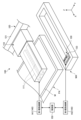
- 2 is a plan view of a portion of the maintenance unit shown in FIG. 1 .
- FIG. 3 is a perspective view of the wiper unit shown in FIG. 2 .
- FIG. 4 is a cross-sectional view of the wiper unit shown in FIG. 3 .
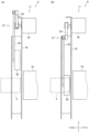
- 4A to 4C are diagrams for explaining the operation of the wiper member and the wiper holding member shown in FIG. 3 .
- 4A to 4C are diagrams for explaining the operation of the wiper member and the wiper holding member shown in FIG. 3 .
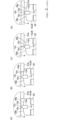
- 13A and 13B are diagrams for explaining a configuration of a maintenance unit according to another embodiment of the present invention.
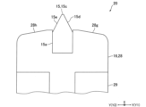
- FIG. 10A and 10B are diagrams illustrating a configuration of a wiper unit according to another embodiment of the present invention.
- FIG. 9 is a perspective view illustrating an example of a printing apparatus according to the present embodiment.
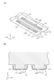
- FIG. 10 is a diagram illustrating an example of an ejection head.
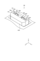
- FIG. 11 is a diagram illustrating an example of the cleaning unit.
- FIG. 12 is a diagram illustrating an example of the cleaning unit.
- FIG. 13 is a diagram illustrating an example of the cleaning unit.
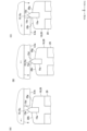
- FIG. 14 is a diagram showing an example of a cleaning operation performed by the cleaning unit.
- FIG. 15 is an enlarged view of a main portion of FIG.
- FIG. 16 is a diagram showing a configuration along the cross section AA of FIG.
- FIG. 1 is a schematic diagram for explaining the configuration of an inkjet printer 1 according to an embodiment of the present invention
- Fig. 2 is a plan view of a portion of a maintenance unit 9 shown in Fig. 1.
- the inkjet printer 1 (hereinafter referred to as "printer 1") of this embodiment is, for example, a commercial inkjet printer that prints on a medium 2 such as paper, fabric, or resin film.
- the medium 2 is, for example, formed in a long shape.
- the printer 1 includes an inkjet head 3 (hereinafter referred to as "head 3") that ejects ink toward the medium 2, a carriage 4 on which the head 3 is mounted, a carriage drive mechanism 5 that moves the carriage 4 in the main scanning direction (Y direction in FIG. 1, etc.) perpendicular to the up-down direction (vertical direction), a Y bar 6 that movably holds the carriage 4, a medium transport mechanism that transports the medium 2, and a platen 7 on which the medium 2 is placed.
- head 3 inkjet head 3
- carriage drive mechanism 5 that moves the carriage 4 in the main scanning direction (Y direction in FIG. 1, etc.) perpendicular to the up-down direction (vertical direction)
- Y bar 6 that mov
- the head 3 ejects ink downward.
- the bottom surface of the head 3 is formed with an ink ejection surface (nozzle surface) 3a on which multiple nozzles that eject ink are arranged.
- the ink ejection surface 3a is arranged below the bottom surface (lower surface) of the carriage 4.
- the ink ejection surface 3a is formed with multiple nozzle rows arranged in the main scanning direction.
- the nozzle rows are made up of a large number of nozzles arranged in a direction perpendicular to the up-down direction and the main scanning direction.
- the ink ejection surface 3a When viewed from the up-down direction, the ink ejection surface 3a has a rectangular outer shape.
- the head 3 is equipped with piezoelectric elements (piezo elements) that eject ink from the nozzles.
- the carriage drive mechanism 5 includes, for example, two pulleys, a belt that is stretched across the two pulleys and is partially fixed to the carriage 4, and a motor that rotates the pulleys.
- the medium transport mechanism includes a transport roller for transporting the medium 2, a roller drive mechanism that drives the transport roller, and a number of pinch rollers that are biased toward the transport roller and pinch the medium 2 between the transport roller and the pinch roller.
- the platen 7 is positioned below the carriage 4. The medium 2 is placed on the platen 7 during printing.
- the main scanning direction (Y direction) is referred to as the "left-right direction”
- the X direction in Fig. 1, etc. which is perpendicular to the up-down and left-right directions, is referred to as the "front-rear direction”.
- the Y1 direction side in Fig. 1, etc., which is one side of the left-right direction, is referred to as the "right” side
- the Y2 direction side in Fig. 1, etc., which is the opposite side of the right side is referred to as the "left” side.
- the left-right direction (Y direction) in this embodiment is the width direction of the medium 2.
- the up-down direction (Z direction) is the thickness direction of the medium 2 placed on the platen 7 during printing
- the front-rear direction (X direction) is the transport direction of the medium 2 moving on the platen 7 and is also the sub-scanning direction.
- the left side (Y2 direction side) is one side of the main scanning direction
- the right side (Y1 direction side) is the other side of the main scanning direction.
- the printer 1 also includes a maintenance unit 9 for preventing clogging of the multiple nozzles of the head 3. If the area in the left-right direction (main scanning direction) where printing is performed on the medium 2 by the head 3 is defined as the printing area PA, the maintenance unit 9 is installed in the maintenance area MA, which is an area outside the printing area PA in the left-right direction. The maintenance unit 9 in this embodiment is located at the right end of the printer 1. The maintenance unit 9 cleans the head 3 to prevent clogging of the multiple nozzles of the head 3.
- the maintenance unit 9 performs purging, which forcibly sucks ink out of the nozzles of the head 3, flushing, which forcibly ejects ink from the nozzles of the head 3, and wiping, which wipes the ink ejection surface 3a with a wiper member 15, which will be described later.
- the maintenance unit 9 includes a capping mechanism 10 for covering the ink ejection surface 3a of the head 3 and sucking ink from the nozzles, and a wiping mechanism 11 for wiping off ink adhering to the ink ejection surface 3a.
- the capping mechanism 10 and wiping mechanism 11 are located below the head 3.
- the capping mechanism 10 is located to the right of the wiping mechanism 11.
- the capping mechanism 10 includes a cap member that covers the ink ejection surface 3a from below. The specific configuration of the wiping mechanism 11 is described below.
- FIG. 3 is a perspective view of the wiper unit 20 shown in Fig. 2.
- Fig. 4 is a cross-sectional view of the wiper unit 20 shown in Fig. 3.
- Figs. 5 and 6 are diagrams for explaining the operation of the wiper member 15 and the wiper holding member 16 shown in Fig. 3.
- the wiping mechanism 11 includes a wiper member 15 that comes into contact with the ink ejection surface 3a of the head 3 to wipe (wipe) the ink ejection surface 3a, a wiper holding member 16 that holds the wiper member 15, a slide member 17 that serves as a holding member that holds the wiper holding member 16 so that it can move up and down, a holding frame 18 that movably holds the slide member 17, and a biasing member 19 (see FIG. 4) that biases the wiper member 15 upward.
- the biasing member 19 is a compression coil spring. Therefore, in the following description, the biasing member 19 will be referred to as a "compression coil spring 19.”
- the holding frame 18 is fixed to the main body frame of the printer 1.
- the slide member 17 is movable in the front-rear direction relative to the holding frame 18.
- the wiper unit 20 is made up of the wiper member 15, wiper holding member 16, slide member 17, and compression coil spring 19. The wiper unit 20 is held by the holding frame 18 so that it can move in the front-rear direction.
- the wiping mechanism 11 also includes a wiper drive mechanism 21 that moves the wiper unit 20 in the front-rear direction relative to the holding frame 18.
- the wiper drive mechanism 21 moves the wiper member 15 in the front-rear direction together with the wiper holding member 16 and the slide member 17. If the front-rear position through which the ink ejection surface 3a of the head 3, which moves left-right together with the carriage 4, passes is defined as the head passing position, the wiper drive mechanism 21 moves the wiper member 15 in the front-rear direction between a wiping possible position (position shown in FIG. 2(B)) where the wiper member 15 is located at the head passing position, and a standby position (position shown in FIG. 2(A)) where the wiper member 15 is out of the head passing position.
- the wiper drive mechanism 21 includes a motor 24, a first lever member 25 having one end fixed to the output shaft of the motor 24, and a second lever member 26 having one end rotatably connected to the other end of the first lever member 25.
- the motor 24 is attached to the holding frame 18.
- the other end of the second lever member 26 is rotatably connected to the slide member 17.
- the slide member 17 is formed in the shape of a rectangular box with an open top. When viewed from the top-bottom direction, the external shape of the slide member 17 is a rectangle that is elongated in the front-to-back direction.
- a through hole 17a is formed in the center of the bottom of the slide member 17.
- the through hole 17a is a circular hole that penetrates the bottom of the slide member 17 in the top-to-bottom direction.
- a ring-shaped recess 17b that surrounds the through hole 17a is formed in the center of the bottom of the slide member 17.
- the recess 17b is recessed downward from the top surface of the bottom of the slide member 17.
- the wiper member 15 and the wiper holding member 16 are formed separately. As described above, the wiper holding member 16 holds the wiper member 15. The upper end of the wiper member 15 protrudes upward from the upper end surface of the wiper holding member 16. A portion of the ink wiped off from the ink ejection surface 3a by the wiper member 15 adheres to the upper end surface of the wiper holding member 16.
- the wiper holding member 16 is formed with a discharge flow path 16a for discharging ink adhering to the upper end surface of the wiper holding member 16 to the lower side of the wiper holding member 16.
- the discharge flow path 16a opens at the upper end surface of the wiper holding member 16 so that the ink adhering to the upper end surface of the wiper holding member 16 flows into the discharge flow path 16a.
- the wiper holding member 16 comprises a first holding member 28 constituting the upper end of the wiper holding member 16, a second holding member 29 to which the first holding member 28 is fixed at the upper end side, and a tubular member 30 formed into a cylindrical shape.
- the wiper holding member 16 in this embodiment is composed of the first holding member 28, the second holding member 29, and the tubular member 30.
- the wiper member 15 is attached to the first holding member 28.
- the first holding member 28 and the second holding member 29 are housed in a slide member 17 formed into a box shape.
- the upper end surface of the wiper holding member 16 (specifically, the upper end surface of the first holding member 28) is located above the upper end of the slide member 17.
- the first holding member 28 is formed in a generally rectangular parallelepiped shape that is elongated in the front-to-rear direction, and when viewed from above and below, the external shape of the first holding member 28 is a rectangle with its long side oriented in the front-to-rear direction.
- Engagement pieces 28a for fixing the first holding member 28 to the second holding member 29 are formed on both ends of the first holding member 28 in the front-to-rear direction.
- the first holding member 28 is fixed to the second holding member 29 by a snap fit that utilizes the elastic deformation of the engagement pieces 28a.
- the first holding member 28 is formed with a positioning recess 28b in which the upper end of the second holding member 29 is positioned.
- the positioning recess 28b is recessed upward from the lower surface of the first holding member 28.
- the outer shape of the positioning recess 28b is a rectangle with its long side oriented in the front-to-rear direction.
- the first holding member 28 is also formed with a positioning hole 28c in which the wiper member 15 is positioned, and a plurality of through holes 28d that form part of the discharge flow path 16a.
- the positioning hole 28c and the through holes 28d are through holes that lead from the upper end surface of the first holding member 28 (i.e., the upper end surface of the wiper holding member 16) to the positioning recess 28b.
- the arrangement hole 28c is a rectangular hole that is elongated in the front-to-rear direction.
- the arrangement hole 28c is formed in the center of the first holding member 28 in the left-to-right direction.
- the arrangement hole 28c is composed of a first hole portion 28e that constitutes the upper part of the arrangement hole 28c, and a second hole portion 28f that constitutes the lower part of the arrangement hole 28c.
- the left-to-right width of the second hole portion 28f is wider than the left-to-right width of the first hole portion 28e.
- the arrangement hole 28c is a stepped rectangular hole.
- the through hole 28d is a rectangular hole with its long side oriented in the front-to-rear direction.
- the through hole 28d is formed on both the left and right sides of the arrangement hole 28c.
- multiple through holes 28d are arranged in the front-to-rear direction at a constant pitch.
- three through holes 28d are arranged in the front-to-rear direction at a constant pitch on both the left and right sides of the arrangement hole 28c.
- the upper end of the through hole 28d is the opening of the discharge flow passage 16a that opens at the upper end surface of the wiper holding member 16.
- an opening of the discharge flow passage 16a is formed in the upper end surface of the first holding member 28.
- the upper end surface of the first retaining member 28 is formed on the part to the right of the arrangement hole 28c with an inclined surface 28g that slopes upward as it approaches the left side.
- the inclined surface 28g slopes gently upward as it approaches the left side.
- the upper end surface of the first retaining member 28 is formed on the part to the left of the arrangement hole 28c with an inclined surface 28h that slopes upward as it approaches the right side.
- the inclination angle of the inclined surface 28g is equal to the inclination angle of the inclined surface 28h.
- the shape of the first retaining member 28 when viewed from the front-to-rear direction is symmetrical with respect to the center line of the first retaining member 28 in the left-to-right direction.
- the second holding member 29 is formed in a rectangular parallelepiped shape that is elongated in the front-rear direction.
- the upper end of the second holding member 29 is disposed in the placement recess 28b of the first holding member 28.
- the left-right width of the upper end of the second holding member 29 is narrower than the left-right width of the portion of the second holding member 29 other than the upper end.
- a discharge flow path 29a that leads to the through hole 28d of the first holding member 28 is formed at the upper end of the second holding member 29.
- the discharge flow path 29a constitutes a part of the discharge flow path 16a.
- a placement recess 29b is formed at the center of the second holding member 29, in which the tubular member 30 is placed.
- the placement recess 29b is recessed upward from the lower surface of the second holding member 29.
- the placement recess 29b is a circular recess.
- a through hole 29c is formed on the upper side of the placement recess 29b, connecting the discharge flow path 29a and the placement recess 29b.
- the through hole 29c forms a part of the discharge flow path 16a.
- An engaged portion 29d is formed at both ends of the second holding member 29 in the front-rear direction, with which the engaging piece 28a of the first holding member 28 engages.
- the tubular member 30 is formed in a cylindrical shape.
- the axial direction of the tubular member 30 coincides with the up-down direction.
- Approximately half of the upper side of the tubular member 30 is disposed in the placement recess 29b of the second holding member 29.
- the upper end surface of the tubular member 30 contacts the bottom surface of the placement recess 29b.
- a ring-shaped flange portion 30a that extends radially outward of the tubular member 30 is formed on the upper end side of the tubular member 30.
- a portion of the tubular member 30 is disposed in the through hole 17a of the slide member 17.
- the lower end portion of the tubular member 30 protrudes downward from the lower surface of the slide member 17.
- the inner diameter of the upper end of the cylindrical member 30 is larger than the inner diameter of the other parts of the cylindrical member 30.
- the inner circumference of the cylindrical member 30 is connected to the through hole 29c of the second holding member 29.
- the inner circumference of the cylindrical member 30 constitutes a part of the discharge flow path 16a. That is, a part of the discharge flow path 16a is formed on the inner circumference of the cylindrical member 30.
- One end of a piping member such as a hose (not shown) is connected to the lower end of the cylindrical member 30.
- the other end of the piping member is connected to a suction pump 32 as a suction mechanism that sucks the ink in the discharge flow path 16a downward. That is, the wiping mechanism 11 is equipped with the suction pump 32. When the suction pump 32 is driven, the ink in the discharge flow path 16a is discharged downward.
- the wiper member 15 comes into contact with the ink ejection surface 3a of the head 3 and wipes off the ink adhering to the ink ejection surface 3a.
- the wiper member 15 is formed of an elastic material.
- the wiper member 15 is formed of rubber.
- the wiper member 15 is formed of ethylene propylene diene rubber (EPDM) or butyl rubber.
- EPDM ethylene propylene diene rubber
- the wiper member 15 is formed of EPDM with a hardness of 40 degrees, or butyl rubber with a hardness of 60 degrees, or butyl rubber with a hardness of 40 degrees.
- the wiper member 15 is formed in an elongated shape that is long and narrow in the front-to-rear direction.
- the front-to-rear width of the wiper member 15 is wider than the front-to-rear width of the ink ejection surface 3a.
- the wiper member 15 is composed of a first wiper portion 15a that constitutes the upper part of the wiper member 15, and a second wiper portion 15b that constitutes the lower part of the wiper member 15.
- the first wiper portion 15a is formed in a generally rectangular parallelepiped shape that is long and narrow in the front-to-rear direction.
- the second wiper portion 15b is formed in a rectangular parallelepiped shape that is long and narrow in the front-to-rear direction.
- the left-to-right width of the first wiper portion 15a is narrower than the left-to-right width of the second wiper portion 15b.
- the upper end of the wiper member 15 protrudes above the upper end surface of the wiper holding member 16.
- the wiper member 15 is disposed in the arrangement hole 28c of the holding member 28.
- the second wiper portion 15b is disposed in the second hole portion 28f of the arrangement hole 28c
- the lower portion of the first wiper portion 15a is disposed in the first hole portion 28e of the arrangement hole 28c.
- the wiper member 15 is inserted into the arrangement hole 28c from the lower side of the arrangement hole 28c. In this embodiment, the wiper member 15 is press-fitted into the arrangement hole 28c.
- the upper end of the wiper member 15 i.e., the upper portion of the first wiper portion 15a
- the wiper upper end portion 15c the upper end of the wiper member 15 that protrudes above the upper end surface of the wiper holding member 16
- the amount of protrusion F of the wiper upper end 15c from the upper end surface of the wiper holding member 16 is approximately 1.5 to 2 (mm).
- An inclined surface 15d is formed on the right side of the wiper upper end 15c, sloping leftward as it goes upward.
- An inclined surface 15e is formed on the left side of the wiper upper end 15c, sloping rightward as it goes upward.
- inclined surface 15d is the first inclined surface
- inclined surface 15e is the third inclined surface.
- the upper end of the wiper upper end 15c (i.e., the upper end of the wiper member 15) is a flat surface that is perpendicular to the up-down direction and has a narrow width in the left-right direction, and the upper end of the wiper upper end 15c is almost pointed.
- the inclination angle of the inclined surface 15d is equal to the inclination angle of the inclined surface 15e.
- the shape of the upper part of the wiper upper end 15c is approximately triangular.
- the shape of the upper part of the wiper upper end 15c is approximately isosceles triangular.
- the shape of the wiper member 15 is symmetrical with respect to the center line of the wiper member 15 in the left-right direction.
- the lower ends of the inclined surfaces 15d and 15e are located above the upper end surface of the wiper holding member 16.
- the upper end surface of the first retaining member 28 has an inclined surface 28g formed on the portion to the right of the arrangement hole 28c, and an inclined surface 28h formed on the portion to the left of the arrangement hole 28c. That is, the upper end surface of the first retaining member 28 has an inclined surface 28g formed on the portion located to the right of the wiper upper end 15c, and an inclined surface 28h formed on the portion located to the left of the wiper upper end 15c.
- the inclined surface 28g in this embodiment is the second inclined surface.
- the lower end of the compression coil spring 19 is disposed in the recess 17b of the slide member 17.
- a part of the tubular member 30 is disposed on the inner periphery of the compression coil spring 19.
- the lower end of the compression coil spring 19 is in contact with the slide member 17. Specifically, the lower end of the compression coil spring 19 is in contact with the lower surface of the recess 17b.
- the upper end of the compression coil spring 19 is in contact with the tubular member 30. Specifically, the upper end of the compression coil spring 19 is in contact with the lower surface of the flange portion 30a of the tubular member 30.
- the compression coil spring 19 biases the tubular member 30 upward relative to the slide member 17. That is, the compression coil spring 19 biases the wiper member 15 and the wiper holding member 16 upward relative to the slide member 17.
- the spring constant of the compression coil spring 19 is small. Therefore, even if the wiper member 15 and the wiper holding member 16 move in the vertical direction, the biasing force of the compression coil spring 19 does not change much.
- the wiper member 15 and the wiper holding member 16 are biased upward by the biasing force of the compression coil spring 19.
- the upper end surface of the wiper member 15 is located above the ink ejection surface 3a of the head 3.
- the upper end surface of the wiper member 15 is located below the lower surface of the carriage 4.
- the upper ends of the inclined surfaces 28g, 28h of the first holding member 28 are located above the ink ejection surface 3a, and the lower ends of the inclined surfaces 28g, 28h are located below the ink ejection surface 3a.
- the ink ejection surface 3a is located below the upper ends of the inclined surfaces 28g and 28h of the first holding member 28 and above the lower ends of the inclined surfaces 28g and 28h.
- the wiping mechanism 11 wipes the ink ejection surface 3a.
- the wiping mechanism 11 does not wipe the ink ejection surface 3a. Therefore, when the carriage 4 moves from the printing area PA to the right toward the capping mechanism 10, the wiper member 15 is disposed in the standby position (see FIG. 2(A)).
- the wiper member 15 moves from the standby position to the wiping-enabled position before the carriage 4 starts moving from the capping mechanism 10 to the left (see FIG. 2(B)).
- the carriage 4 moves to the left.
- the left end of the ink ejection surface 3a i.e., the left end of the head 3
- the wiper member 15 and the wiper holding member 16 move down against the biasing force of the compression coil spring 19 (see Figures 5 (A) and (B)).
- the left end of the ink ejection surface 3a reaches the wiper member 15, and the head 3 comes into contact with the inclined surface 15d.
- the wiping mechanism 11 includes the compression coil spring 19 for biasing the wiper member 15 upward. Therefore, in this embodiment, even if the protrusion amount F of the wiper upper end 15c that protrudes above the upper end surface of the wiper holding member 16 is reduced (i.e., even if the length of the wiper upper end 15c in the vertical direction is shortened), the wiper member 15 can be brought into contact with the ink ejection surface 3a at a predetermined contact pressure. That is, in this embodiment, it is possible to reduce the protrusion amount F of the wiper upper end 15c. Therefore, in this embodiment, it is possible to reduce the amount of elastic deformation of the wiper member 15 when the upper end surface of the wiper member 15 is in contact with the ink ejection surface 3a.
- the wiper member 15 moves upwards when the right end of the ink ejection surface 3a of the head 3, which moves leftward together with the carriage 4, passes through the wiper member 15 in a state of wiping the ink ejection surface 3a and the wiper member 15 detaches from the ink ejection surface 3a. Therefore, in this embodiment, it is possible to suppress the splashing of ink when the wiper member 15 detaches from the ink ejection surface 3a.
- an inclined surface 15d is formed on the right side of the wiper upper end 15c, and the left end of the head 3, which moves leftward together with the carriage 4, comes into contact with the inclined surface 15d, so that when the head 3 comes into contact with the wiper member 15, it is possible to disperse the force transmitted from the head 3 to the wiper member 15.
- the wiper member 15 can move up and down together with the wiper holding member 16 relative to the slide member 17, so that when the head 3 comes into contact with the wiper member 15, the wiper member 15 is lowered, so that it is possible to dissipate the impact when the head 3 comes into contact with the wiper member 15. Therefore, in this embodiment, it is possible to prevent damage to the wiper member 15 caused by contact between the head 3 and the wiper member 15.
- the shape of the wiper member 15 when viewed from the front-rear direction is linearly symmetrical with respect to the center line of the wiper member 15 in the left-right direction. Therefore, in this embodiment, it is possible to prevent mistakes in the installation direction of the wiper member 15 when attaching the wiper member 15 to the wiper holding member 16.
- the wiper holding member 16 is formed with a discharge flow path 16a for discharging ink adhering to the upper end surface of the wiper holding member 16 to the lower side of the wiper holding member 16, and the discharge flow path 16a opens at the upper end surface of the wiper holding member 16. Therefore, in this embodiment, it is possible to remove ink adhering to the upper end surface of the wiper holding member 16 by utilizing the discharge flow path 16a. Therefore, in this embodiment, it is possible to prevent ink adhering to the upper end surface of the wiper holding member 16 from flowing down onto the components of the maintenance unit 9, and as a result, it is possible to prevent contamination of the components of the maintenance unit 9 caused by ink adhering to the upper end surface of the wiper holding member 16.
- the wiping mechanism 11 is equipped with a suction pump 32 that sucks ink downward from the discharge flow path 16a, so that the suction pump 32 can be used to effectively remove ink adhering to the upper end surface of the wiper holding member 16. Therefore, in this embodiment, it is possible to effectively prevent ink adhering to the upper end surface of the wiper holding member 16 from flowing down onto the components of the maintenance unit 9, and as a result, it is possible to effectively prevent contamination of the components of the maintenance unit 9 caused by ink adhering to the upper end surface of the wiper holding member 16.
- the wiper member 15 is biased upward by a compression coil spring 19 whose lower end contacts the slide member 17 and whose upper end contacts the cylindrical member 30. Therefore, in this embodiment, it is possible to bias the wiper member 15 upward with a relatively simple configuration.
- the ink ejection surface 3a may be positioned above the lower ends of the inclined surfaces 15d and 15e of the wiper member 15 (see FIG. 7).
- the left end of the head 3 which moves leftward together with the carriage 4, directly contacts the inclined surface 15d.
- the wiper member 15 descends against the biasing force of the compression coil spring 19, and the upper end surface of the wiper member 15 contacts the ink ejection surface 3a (see FIGS. 7A and 7B).
- the wiper member 15 wipes off the ink adhering to the ink ejection surface 3a (see FIG. 7B).
- the lower ends of the inclined surfaces 15d and 15e may be located below the upper end surface of the wiper holding member 16.
- the carriage 4 may be provided with a lifting mechanism for changing the height of the ink ejection surface 3a of the head 3, and even if the height of the ink ejection surface 3a changes, the left end of the head 3 moving to the left together with the carriage 4 will come into contact with the inclined surface 15d or the inclined surface 28g.
- the head 3 can be moved smoothly along the inclined surfaces 15d and 28g, and as a result, the wiper member 15 and the wiper holding member 16 can be smoothly lowered.
- the upper end of the inclined surface 15d and the upper end of the inclined surface 15e are connected, and a plane perpendicular to the up-down direction may not be formed at the upper end of the wiper upper end 15c.
- the inclined surface 15e may not be formed on the wiper member 15, and the inclined surface 28h may not be formed on the first holding member 28.
- the wiper member 15 and the wiper holding member 16 can be smoothly lowered when the left end of the head 3 contacts the wiper member 15, the inclined surface 15d may not be formed on the wiper member 15.
- the inclined surface 28g may not be formed on the first holding member 28.
- the biasing member for biasing the wiper member 15 upward may be a spring member other than the compression coil spring 19.
- the wiping mechanism 11 may be provided with a drive mechanism for moving the wiper member 15 up and down, instead of the compression coil spring 19.
- the drive mechanism includes, for example, a motor as a drive source, and a power transmission mechanism for transmitting the power of the motor to the wiper member 15.
- the drive mechanism may be, for example, a cylinder such as an air cylinder.
- the drive mechanism moves the wiper member 15 upward.
- the wiper member 15 moves upward.
- the wiper member 15 waits in a position where the upper end face of the wiper member 15 is located below the ink ejection surface 3a until the left end of the ink ejection surface 3a of the head 3 moving to the left together with the carriage 4 reaches the wiper member 15, and when the left end of the ink ejection surface 3a reaches the wiper member 15, the wiper member 15 moves upward to a position where the upper end face of the wiper member 15 contacts the ink ejection surface 3a.
- the inclined surfaces 15d and 15e do not need to be formed on the wiper member 15, and the inclined surfaces 28g and 28h do not need to be formed on the first holding member 28.
- the wiping mechanism 11 is provided with a compression coil spring 19 as in the above-described embodiment, it is possible to simplify the configuration of the wiping mechanism 11 and reduce the cost of the wiping mechanism 11 compared to when the wiping mechanism 11 is provided with a drive mechanism for moving the wiper member 15 up and down.
- the wiping mechanism 11 may not include the suction pump 32.
- the ink that has passed through the discharge flow path 16a is discharged downward from the cylindrical member 30 by its own weight.
- the discharge flow path 16a may not be formed in the wiper holding member 16.
- the wiper member 15 may be formed of an elastic material other than rubber.
- the medium 2 may not be formed in a long shape.
- the printer 1 includes, for example, a table on which the medium 2 is placed, and a table feed mechanism that moves the table in the front-rear direction.
- the inkjet printer to which the present invention is applied may be a printer for general consumers, or may be a 3D printer.
- the wiper member 15 and the wiper holding member 16 can be integrally formed.
- the wiper member 15 and the wiper holding member 16 are formed of rubber such as EPDM.
- the wiper member 15 and the wiper holding member 16 may be deformed by immersion in ink, so the wiper member 15 and the wiper holding member 16 are classified as consumables.
- the wiper member 15 and the wiper holding member 16 must be replaced together.
- the wiper member 15 when the wiper member 15 is usable but the wiper member 15 wears out and cannot be used, the wiper member 15 and the wiper holding member 16 must be replaced together. Therefore, when the wiper member 15 and the wiper holding member 16 are integrally formed, there is a risk of an increase in running costs. In contrast, if the wiper member 15 and the wiper holder 16 are formed separately, as in the embodiment described above, this problem does not occur.
- the directions in the figure are explained using an XYZ coordinate system.
- a plane parallel to the floor on which the inkjet printer is placed is defined as the XY plane.
- the transport direction of the recording medium 2, which will be described later is written as the X direction
- the direction perpendicular to the X direction on the XY plane is written as the Y direction.
- the direction perpendicular to the XY plane is written as the Z direction.
- the X, Y, and Z directions are explained assuming that the direction of the arrow in the figure is the + direction, and the direction opposite to the arrow direction is the - direction. Note that in this embodiment, the +Z direction may be written as upward.
- FIG. 9 is a perspective view that shows a schematic example of a printing device according to this embodiment.
- the printing device 100 shown in FIG. 9 is an inkjet printer that performs printing on media M using an inkjet method.
- the printing device 100 includes a carriage 110, a guide mechanism 120, a cleaning unit 130, a drive unit 140, and a control unit 150.
- the carriage 110 is guided by a guide mechanism 120 and can move back and forth in the Y direction (main scanning direction).
- the carriage 110 has an ejection head 111.
- the carriage 110 may also be provided with a light irradiation device (not shown).
- the ejection head 111 ejects ink toward the medium M in the printing area PA.
- the medium M is placed on a platen 116 in the printing area PA.
- Figure 10 shows an example of an ejection head 111.
- Figure 10(A) shows an oblique view
- Figure 10(B) shows a cross-sectional view.
- the ejection head 111 has a nozzle surface 113.
- the nozzle surface 113 is, for example, planar, and has nozzles 114 formed thereon for ejecting ink.
- the nozzle surface 113 is treated to be water-repellent in order to ensure a meniscus of the ink at the nozzles 114.
- the nozzles 114 are arranged, for example, in a line in a predetermined direction.
- the ink include ultraviolet-curable ink. Types of ultraviolet-curable ink include white ink, colored inks such as cyan (C), magenta (M), yellow (Y) and black (K), and transparent ink, depending on the color of the image to be formed on the medium M.
- Ink other than ultraviolet-curable ink can also be used as appropriate for inks such as latex ink, which are prone to adhere solid matter to the nozzle surface as the ink dries and hardens.
- the longest non-ejection time is the longest time it takes for the ejection head 111 to reach a position facing the wiping unit 132 after ejecting ink for the last time in the main scanning direction (Y direction)
- the ink that can be used can be one in which the ink droplets adhering to the nozzle surface 113 solidify at least during the longest non-ejection time.
- the ejection head 111 has a nozzle plate 115 disposed on a nozzle surface 113.
- the nozzle plate 115 is formed to surround a nozzle region 113R of the nozzle surface 113 in which multiple nozzles 114 are formed. For this reason, a step is formed on the nozzle surface 113 between the nozzle region 113R and the plate surface 117, which is the bottom surface of the nozzle plate 115.
- the step is formed, for example, by the thickness of the nozzle plate 115.
- two ejection heads 111 are arranged in the Y direction. Note that one ejection head 111 or three or more ejection heads 111 may be arranged in the Y direction.
- the guide mechanism 120 guides the carriage 110 in the Y direction.
- the guide mechanism 120 has a guide rail 121.
- the guide rail 121 extends along the Y direction.
- the cleaning unit 130 is provided in the maintenance area MA of the printing device 100.
- the maintenance area MA is disposed outside the printing area PA in the Y direction.
- the cleaning unit 130 cleans the ejection head 111.
- FIGS. 11 to 13 are diagrams showing an example of the cleaning unit 130.
- FIG. 11 is a perspective view
- FIG. 12 is an exploded perspective view
- FIG. 13 is a cross-sectional view.
- the cleaning unit 130 has a suction unit 131, a wiping unit 132, and a support unit 133.
- the suction units 131 and wiping units 132 are arranged in numbers corresponding to the ejection heads 111. In this embodiment, two suction units 131 and two wiping units 132 are arranged.
- the suction unit 131 surrounds and suctions a portion of the plate surface 117 of the nozzle plate 115.
- the suction unit 131 has a frame portion 134 and a suction nozzle 135.
- the frame portion 134 has a side wall 134a, a contact portion 134b, an opening 134c, and a storage portion 134d.
- the contact portion 134b is disposed on the upper portion of the side wall 134a.
- the contact portion 134b is disposed along the XY plane.
- the contact portion 134b is disposed opposite the plate surface 117, and comes into contact with the plate surface 117 when the cleaning portion 130 rises or the ejection head 111 descends.
- the openings 134c are formed to extend in the Y direction. Two openings 134c are arranged in the Y direction, corresponding to the number of ejection heads 111.
- the dimension of each opening 134c in the Y direction is larger than the dimension of the plate surface 117 in the Y direction. That is, the plate surface 117 has a dimension in the Y direction that fits inside the openings 134c. This allows the suction unit 131 to suck the plate surface 117 over the entire Y direction.
- the openings 134c may be configured so that the dimension in the Y direction is larger than the nozzle region 113R, and in this case, the dimension in the Y direction of the openings 134c may be smaller than that of the plate surface 117.
- the accommodation unit 134d is arranged inside each opening 134c. The accommodation unit 134d accommodates the wiping unit 132. That is, the wiping unit 132 is narrower in width than the openings 134c.
- the suction nozzles 135 are disposed inside the frame portion 134.
- a suction nozzle 135 is provided for each opening 134c.
- the suction nozzles 135 are disposed below (in the -Z direction) the openings 134c.
- the suction nozzles 135 have a suction port 135b formed on the upper (+Z) end face 135a of the suction nozzle 135.
- Each suction nozzle 135 is connected to a suction source, such as a pump (not shown).
- the wiping unit 132 wipes the nozzle surface 113 of the ejection head 111, which is surrounded by the nozzle plate 115.
- the wiping unit 132 is accommodated in the accommodation portion 134d of the frame portion 134 described above. Therefore, the wiping unit 132 is disposed inside the opening 134c of the suction unit 131.
- the wiping unit 132 is also supported by the end surface 135a of the suction nozzle 135 described above.
- the wiping unit 132 is provided so as to be detachable from the suction unit 131.
- the wiping portion 132 is formed using an elastic material such as a rubber material. It is preferable that the wiping portion 132 is formed using an elastic material such as a rubber material with a rubber hardness of 50° to 70°.
- the rubber hardness can be a value measured using a measurement method specified in the JIS standard "JIS K 6253-3.”
- the wiping part 132 has a base 132a and a contact part 132b.
- the base 132a is formed, for example, in a rectangular block shape.
- the base 132a is placed on the end surface 135a of the suction nozzle 135 described above.
- the contact part 132b protrudes from the base 132a in the +Z direction.
- the contact part 132b has a tapered shape from the base 132a side toward the tip side (+Z direction).
- the contact part 132b has a shape inclined on both sides in the X direction.
- the drive unit 140 moves the carriage 110 and the cleaning unit 130, thereby moving the nozzle surface 113 and the cleaning unit 130 relative to each other.
- the drive unit 140 has a first drive mechanism 141 and a second drive mechanism 142.
- the first drive mechanism 141 moves the carriage 110 in the Y direction.
- the first drive mechanism 141 includes a drive source, such as a motor, and a transmission mechanism.
- the carriage 110 moves in the Y direction along the guide rail 121 by the drive force generated by the drive source of the first drive mechanism 141.
- the first drive mechanism 141 moves the two ejection heads 111 as a unit.
- the second drive mechanism 142 moves the cleaning unit 130 back and forth in the X direction (sub-scanning direction).
- the second drive mechanism 142 can switch the movement speed of the cleaning unit 130.
- the second drive mechanism 142 can switch the movement speed of the cleaning unit 130 between a first speed V1 that is suitable for performing a suction operation by the suction unit 131, and a second speed V2 that is suitable for performing a wiping operation by the wiping unit 132.
- the first speed V1 is slower than the second speed V2.
- the second drive mechanism 142 can change the movement speed of the cleaning unit 130 when moving the cleaning unit 130 in one direction in the X direction (forward path) and when moving the cleaning unit 130 in the other direction in the X direction (return path). For example, the second drive mechanism 142 may move the cleaning unit 130 at a first speed V1 on the forward path and at a second speed V2 on the return path. The second drive mechanism 142 may move the cleaning unit 130 at a second speed V2 on the forward path and at a first speed V1 on the return path.
- the second drive mechanism 142 can also move the cleaning unit 130 back and forth in the Z direction (up and down direction). By moving the cleaning unit 130 in the +Z direction, the second drive mechanism 142 can bring the frame unit 134 of the suction unit 131 into contact with the plate surface 117 and bring the wiping unit 132 into contact with the nozzle surface 113. By moving the suction unit 131 in the -Z direction, the second drive mechanism 142 can release the contact between the frame unit 134 and the plate surface 117 and release the contact between the wiping unit 132 and the nozzle surface 113.
- the second drive mechanism 142 brings the frame portion 134 into contact with the plate surface 117 and the wiping portion 132 into contact with the nozzle surface 113, and starts suction with the suction nozzle 135.
- the suction portion 131 can suck the nozzle plate 115, and the wiping portion 132 can wipe the nozzle surface 113.
- the control unit 150 comprehensively controls the operation of each unit of the printing device 100.
- the control unit 150 controls the drive operation of the drive unit 140.
- the control unit 150 controls the operation of a suction source (not shown) to control the suction operation of the suction unit 131.
- FIG. 14 is a diagram showing an example of the cleaning operation by the cleaning unit 130.
- the ejection head 111 When performing the cleaning operation, the ejection head 111 is moved above the cleaning unit 130. From this state, as shown in FIG. 14, the second drive mechanism 142 raises the cleaning unit 130 toward the ejection head 111. Note that the ejection head 111 may also be moved downward by the first drive mechanism 141. As the cleaning unit 130 rises, the contact portion 134b of the frame portion 134 of the suction unit 131 comes into contact with the plate surface 117, and the contact portion 132b of the wiping unit 132 comes into contact with the nozzle surface 113.
- FIG. 15 is an enlarged view of the main parts of FIG. 14.
- FIG. 16 is a view showing the configuration along the A-A cross section of FIG. 15.
- the suction portion 131 can suck the entire Y direction of the plate surface 117.
- the contact portion 132b of the wiping portion 132 enters the opening of the nozzle plate 115 and comes into contact with the nozzle surface 113. This allows the wiping portion 132 to directly wipe the nozzle surface 113.
- the drive unit 140 moves the ejection head 111 and the cleaning unit 130 relative to each other in the X direction.
- the second drive mechanism 142 moves the cleaning unit 130 in the X direction.
- the second drive mechanism 142 moves the cleaning unit 130 in one direction in the X direction (outward path) while causing the suction nozzle 135 to perform a suction operation.
- the second drive mechanism 142 moves the cleaning unit 130 at a first speed V1. This movement causes the cleaning unit 130 to move in one direction in the X direction at a moving speed suitable for the suction operation of the suction unit 131, so that foreign matter (ink, ink aggregates, etc.) adhering to the plate surface 117 of the nozzle plate 115 can be appropriately sucked up.
- the second drive mechanism 142 moves the cleaning unit 130 in the other direction in the X direction (return path) while causing the suction nozzle 135 to perform a suction operation.
- the second drive mechanism 142 moves the cleaning unit 130 at a second speed V2. This movement causes the cleaning unit 130 to move in the other direction in the X direction at a movement speed suitable for the wiping operation of the wiping unit 132, so that foreign matter (ink, ink aggregates, etc.) adhering to the nozzle surface 113 can be properly wiped away.
- the wiping part 132 is formed using an elastic material (e.g., a rubber material) with a rubber hardness of 50° to 70°.
- the second drive mechanism 142 does not need to change the movement speed of the cleaning part 130 between the forward and return paths.
- the second drive mechanism 142 may move the cleaning part 130 at a first speed V1 on both the forward and return paths.
- the second drive mechanism 142 may also move the cleaning part 130 at a second speed V2 on both the forward and return paths.
- the printing device 100 includes an ejection head 111 having a nozzle surface 113 on which a plurality of nozzles 114 for ejecting ink are formed in a row at a predetermined interval, a cleaning unit 130 for cleaning the nozzle surface 113, and a drive unit 140 for relatively moving the nozzle surface 113 and the cleaning unit 130.
- the ejection head 111 further includes a nozzle plate 115 arranged to surround a nozzle region 113R on the nozzle surface 113 in which the nozzles 114 are formed, and a step is formed between the nozzle surface 113 and the nozzle plate 115 by the thickness of the nozzle plate 115.
- the cleaning unit 130 includes a suction unit 131 that surrounds and sucks a portion of the plate surface 117 of the nozzle plate 115, and a wiping unit 132 that is arranged inside the suction unit 131 and wipes the nozzle surface 113 surrounded by the nozzle plate 115.
- the suction unit 131 can suck the plate surface 117 of the nozzle plate 115, and the wiping unit 132 can wipe the nozzle surface 113 surrounded by the nozzle plate 115. This makes it possible to properly remove foreign matter adhering to the plate surface 117 and nozzle surface 113 of the ejection head 111.
- the drive unit 140 moves the nozzle surface 113 and the cleaning unit 130 back and forth relative to one another to perform the cleaning operation.
- the drive unit 140 moves the nozzle surface 113 and the cleaning unit 130 relative to one another by switching between a first speed V1 corresponding to the suction operation by the suction unit 131 and a second speed V2 corresponding to the wiping operation by the wiping unit 132.
- the suction operation and wiping operation can be performed appropriately by switching between a first speed V1 suitable for suction operation and a second speed V2 suitable for wiping operation.
- the wiping unit 132 is inclined on at least one side in the direction of relative movement with the nozzle surface 113 so as to taper toward the nozzle surface 113.
- This configuration allows the wiping unit 132 to perform an appropriate wiping operation in both the forward and backward directions of the relative movement.
- the wiping unit 132 is made of an elastic material that deforms upon contact with the nozzle surface 113 when the wiping unit 132 moves back and forth relative to the nozzle surface 113 and the cleaning unit 130.
- the wiping portion 132 is formed using an elastic material with a rubber hardness of 50° to 70°.
- This configuration allows the wiping unit 132 to perform an appropriate wiping operation regardless of the movement speed of the cleaning unit 130.
- the suction unit 131 has a contact portion 134b that contacts the ejection head 111, and the contact portion 134b has an opening 134c that is wider than at least the nozzle region 113R, and the width of the wiping portion 132 is narrower than the width of the opening 134c.
- the width of the opening 134c is wider than the nozzle region 113R, so the entire width of the nozzle region 113R can be reliably sucked. Also, the width of the wiping portion 132 is narrower than the width of the opening 134c, so the nozzle region 113R located inside the opening 134c can be reliably wiped by the wiping portion 132.
- the wiping unit 132 is detachable from the suction unit 131.
- This configuration makes it easy to perform maintenance on the wiping section 132 and the suction section 131.
- the contact portion 132b of the wiping portion 132 is configured to be tapered from the base portion 132a to the tip, but is not limited to this configuration.
- the contact portion 132b may be configured in a columnar shape that is not tapered from the base portion 132a to the tip.
Landscapes
- Ink Jet (AREA)
Abstract
このインクジェットプリンタでは、インクジェットヘッド(3)の複数のノズルの目詰まりを防止するためのメンテナンスユニットは、ワイパー部材(15)を上側に向かって付勢するための付勢部材またはワイパー部材(15)を上下動させるための駆動機構を備えている。このインクジェットプリンタでは、キャリッジ(4)と一緒に主走査方向の一方側に移動するインクジェットヘッド(3)のインク吐出面(3a)の主走査方向の他方側端が、インク吐出面(3a)を拭き取っている状態のワイパー部材(15)を通過して、インク吐出面(3a)からワイパー部材(15)が外れるときに、ワイパー部材(15)が上側に移動する。
Description
本発明は、インクジェットヘッドのインク吐出面に接触してインク吐出面を拭き取るためのワイパー部材を備えるインクジェットプリンタに関する。
また、本発明は、印刷装置に関する。
従来、インクを吐出して媒体に印刷を行うインクジェットプリンタが知られている(たとえば、特許文献1参照)。特許文献1に記載のインクジェットプリンタは、インクを吐出するインクジェットヘッドと、インクジェットヘッドが搭載されるキャリッジと、主走査方向にキャリッジを移動させるキャリッジ駆動機構とを備えている。インクジェットヘッドの下面には、複数のノズルが配列されるインク吐出面(ノズル面)が形成されている。また、このインクジェットプリンタは、インクジェットヘッドの複数のノズルの目詰まりを防止するためのメンテナンスユニットを備えている。メンテナンスユニットは、インクジェットヘッドのインク吐出面に付着したインクを拭き取るためのワイピング機構を備えている。
特許文献1に記載のインクジェットプリンタでは、ワイピング機構は、インク吐出面を拭うワイパー部材と、ワイパー部材が固定されるワイパー保持部材と、上下方向と主走査方向とに直交する前後方向にワイパー保持部材を移動させるワイパー駆動機構とを備えている。ワイパー部材は、たとえば、ゴムで形成されており、弾力性を備えている。特許文献1に記載のインクジェットプリンタでは、前後方向においてワイパー部材がインクジェットヘッドと同じ位置に配置された状態でキャリッジが主走査方向に移動すると、ワイパー部材がインク吐出面に接触して、インク吐出面に付着したインクを拭き取る。このときには、インク吐出面に接触するワイパー部材の上端部は大きく弾性変形している。
また、ノズル面に形成されたノズルからインクを噴射する噴射ヘッドを有する印刷装置においては、噴射ヘッドのノズル面に付着したインクを吸引する吸引部と、ノズル面に付着したインクを払拭する払拭部とを備えた構成が知られている(例えば、特許文献2参照)。
特許文献1に記載のインクジェットプリンタでは、ワイパー部材が弾力性を有するゴム等によって形成されており、インク吐出面のインクを拭き取るときにインク吐出面に接触するワイパー部材の上端部は大きく弾性変形している。そのため、このインクジェットプリンタでは、インク吐出面に接触してインク吐出面のインクを拭き取っていたワイパー部材が主走査方向へのキャリッジの移動に伴ってインク吐出面から外れるときに、ワイパー部材の上端部が元の形状に戻るように大きくかつ急激に復元するおそれがある。ワイパー部材の上端部が大きくかつ急激に復元すると、ワイパー部材に付着していたインクが飛び散って、ワイピング機構の周囲を汚すおそれがある。
そこで、本発明の課題は、インクジェットヘッドのインク吐出面に接触してインク吐出面を拭き取るためのワイパー部材を備えるインクジェットプリンタにおいて、ワイパー部材がインク吐出面から外れるときのインクの飛び散りを抑制することが可能なインクジェットプリンタを提供することにある。
また、特許文献2のような印刷装置においては、噴射ヘッドのノズル面のうちノズルが形成されたノズル領域を囲うようにノズルプレートが設けられる場合がある。この構成では、ノズルプレートの表面とノズル面のノズル領域との間に段差が形成される。したがって、ノズル面を払拭部で直接払拭することができず、ノズル面に付着する異物を適切に除去することができない等の問題がある。
本発明は、上記に鑑みてなされたものであり、噴射ヘッドに付着する異物を適切に除去することが可能な印刷装置を提供することを目的とする。
上記の課題を解決するため、本発明のインクジェットプリンタは、インクを吐出するインクジェットヘッドと、インクジェットヘッドが搭載されるキャリッジと、上下方向に直交する主走査方向にキャリッジを移動させるキャリッジ駆動機構と、インクジェットヘッドの複数のノズルの目詰まりを防止するためのメンテナンスユニットとを備え、インクジェットヘッドの下面には、複数のノズルが配置されるインク吐出面が形成され、メンテナンスユニットは、インク吐出面に接触してインク吐出面を拭き取るためのワイパー部材と、ワイパー部材を上側に向かって付勢するための付勢部材またはワイパー部材を上下動させるための駆動機構とを備え、キャリッジと一緒に主走査方向の一方側に移動するインクジェットヘッドのインク吐出面の主走査方向の他方側端が、インク吐出面を拭き取っている状態のワイパー部材を通過して、インク吐出面からワイパー部材が外れるときに、ワイパー部材が上側に移動することを特徴とする。
本発明のインクジェットプリンタでは、メンテナンスユニットは、ワイパー部材を上側に向かって付勢するための付勢部材またはワイパー部材を上下動させるための駆動機構を備えている。そのため、ワイパー部材の、ワイパー部材の上端がインク吐出面に接触したときに弾性変形可能な部分を弾性変形可能部とすると、本発明では、弾性変形可能部の上下方向の長さを短くしても、ワイパー部材をインク吐出面に所定の接触圧で接触させることが可能になる。すなわち、本発明では、弾性変形可能部の上下方向の長さを短くすることが可能になる。したがって、本発明では、インク吐出面にワイパー部材の上端が接触しているときの、ワイパー部材の弾性変形量を低減することが可能になる。
また、本発明では、インク吐出面にワイパー部材の上端が接触しているときの、ワイパー部材の弾性変形量を低減することが可能になるのに加えて、キャリッジと一緒に主走査方向の一方側に移動するインクジェットヘッドのインク吐出面の主走査方向の他方側端が、インク吐出面を拭き取っている状態のワイパー部材を通過して、インク吐出面からワイパー部材が外れるときに、ワイパー部材が上側に移動している。そのため、本発明では、ワイパー部材がインク吐出面から外れるときのインクの飛び散りを抑制することが可能になる。
本発明において、メンテナンスユニットは、付勢部材を備え、キャリッジと一緒に主走査方向の一方側に移動するインクジェットヘッドのインク吐出面の主走査方向の一方側端がワイパー部材に到達すると、ワイパー部材が付勢部材の付勢力に抗して降下し、ワイパー部材の上端がインク吐出面に接触することが好ましい。このように構成すると、ワイパー部材を上下動させるための駆動機構をメンテナンスユニットが備えている場合と比較して、メンテナンスユニットの構成を簡素化することが可能になるとともに、メンテナンスユニットのコストを低減することが可能になる。
本発明において、メンテナンスユニットは、ワイパー部材を保持するワイパー保持部材を備え、ワイパー部材の上端部は、ワイパー保持部材の上端面よりも上側に突出し、付勢部材は、ワイパー部材およびワイパー保持部材を上側に向かって付勢し、ワイパー保持部材の上端面よりも上側に突出するワイパー部材の上端部をワイパー上端部とすると、ワイパー上端部の、主走査方向の他方側の側面には、上側に向かうにしたがって主走査方向の一方側に向かうように傾斜する第1傾斜面が形成され、ワイパー保持部材の上端面の、主走査方向においてワイパー上端部の他方側に配置される部分には、主走査方向の一方側に向かうにしたがって上側に向かうように傾斜する第2傾斜面が形成されていることが好ましい。
このように構成すると、キャリッジと一緒に主走査方向の一方側に移動するインクジェットヘッドがワイパー部材またはワイパー保持部材に接触したときに、インクジェットヘッドを第1傾斜面または第2傾斜面に沿ってスムーズに移動させることが可能になる。したがって、キャリッジと一緒に主走査方向の一方側に移動するインクジェットヘッドがワイパー部材またはワイパー保持部材に接触したときに、ワイパー部材およびワイパー保持部材をスムーズに降下させることが可能になる。
本発明において、ワイパー上端部の、主走査方向の一方側の側面には、上側に向かうにしたがって主走査方向の他方側に向かうように傾斜する第3傾斜面が形成され、上下方向と主走査方向とに直交する方向から見たときのワイパー部材の形状は、主走査方向におけるワイパー部材の中心線に対して線対称な形状になっていることが好ましい。このように構成すると、ワイパー保持部材にワイパー部材を取り付けるときの、ワイパー部材の取付方向の間違いを防止することが可能になる。
本発明において、メンテナンスユニットは、ワイパー部材を保持するワイパー保持部材を備え、ワイパー部材の上端部は、ワイパー保持部材の上端面よりも上側に突出し、ワイパー保持部材には、ワイパー保持部材の上端面に付着するインクをワイパー保持部材の下側に排出するための排出流路が形成され、排出流路は、ワイパー保持部材の上端面で開口していることが好ましい。このように構成すると、排出流路を利用して、ワイパー保持部材の上端面に付着するインクを除去することが可能になるため、ワイパー保持部材の上端面に付着するインクがメンテナンスユニットの構成部品の上に流れ落ちるのを抑制することが可能になる。したがって、ワイパー保持部材の上端面に付着するインクに起因するメンテナンスユニットの構成部品の汚れを抑制することが可能になる。
本発明において、メンテナンスユニットは、排出流路のインクを下側に向かって吸引する吸引機構を備えることが好ましい。このように構成すると、吸引機構を利用して、ワイパー保持部材の上端面に付着するインクを効果的に除去することが可能になる。したがって、ワイパー保持部材の上端面に付着するインクがメンテナンスユニットの構成部品の上に流れ落ちるのを効果的に抑制することが可能になり、その結果、ワイパー保持部材の上端面に付着するインクに起因するメンテナンスユニットの構成部品の汚れを効果的に抑制することが可能になる。
本発明において、たとえば、メンテナンスユニットは、付勢部材と、ワイパー保持部材を上下動可能に保持する保持部材とを備え、付勢部材は、保持部材に対してワイパー部材およびワイパー保持部材を上側に向かって付勢する圧縮コイルバネであり、ワイパー保持部材は、排出流路の一部分が内周側に形成される筒状の筒状部材を備え、筒状部材の軸方向は、上下方向と一致し、筒状部材の一部は、圧縮コイルバネの内周側に配置され、圧縮コイルバネの上端は、筒状部材に接触し、圧縮コイルバネの下端は、保持部材に接触している。この場合には、比較的簡易な構成によって、ワイパー部材を上側に向かって付勢することが可能になる。
また、本発明に係る印刷装置は、インクを噴射するノズルが所定の間隔で複数連なって形成されているノズル面を有する噴射ヘッドと、前記ノズル面を清掃する清掃部と、前記ノズル面と前記清掃部とを相対的に移動させる駆動部とを備え、前記噴射ヘッドは、前記ノズル面のうち前記ノズルが形成されたノズル領域を囲うように配置されるノズルプレートを更に有し、前記ノズル面と前記ノズルプレートとの間には、前記ノズルプレートの厚さ分の段差が形成され、前記清掃部は、前記ノズルプレートの表面の一部を囲んで吸引する吸引部と、前記吸引部の内側に配置され、前記ノズルプレートに囲まれる前記ノズル面を払拭する払拭部とを有する。
以上のように、本発明では、インクジェットヘッドのインク吐出面に接触してインク吐出面を拭き取るためのワイパー部材を備えるインクジェットプリンタにおいて、ワイパー部材がインク吐出面から外れるときのインクの飛び散りを抑制することが可能になる。
また、本発明によれば、噴射ヘッドに付着する異物を適切に除去することが可能な印刷装置を提供することができる。
<第1実施形態>
以下、図面を参照しながら、本発明の実施の形態を説明する。
以下、図面を参照しながら、本発明の実施の形態を説明する。
(インクジェットプリンタの全体構成)
図1は、本発明の実施の形態にかかるインクジェットプリンタ1の構成を説明するための概略図である。図2は、図1に示すメンテナンスユニット9の一部の平面図である。
図1は、本発明の実施の形態にかかるインクジェットプリンタ1の構成を説明するための概略図である。図2は、図1に示すメンテナンスユニット9の一部の平面図である。
本形態のインクジェットプリンタ1(以下、「プリンタ1」とする。)は、たとえば、業務用のインクジェットプリンタであり、紙、布帛または樹脂製のフィルム等の媒体2に対して印刷を行う。媒体2は、たとえば、長尺状に形成されている。プリンタ1は、媒体2に向かってインクを吐出するインクジェットヘッド3(以下、「ヘッド3」とする。)と、ヘッド3が搭載されるキャリッジ4と、上下方向(鉛直方向)に直交する主走査方向(図1等のY方向)にキャリッジ4を移動させるキャリッジ駆動機構5と、キャリッジ4を移動可能に保持するYバー6と、媒体2を搬送する媒体搬送機構と、媒体2が載置されるプラテン7とを備えている。
ヘッド3は、下側に向かってインクを吐出する。ヘッド3の下面には、インクを吐出する複数のノズルが配置されるインク吐出面(ノズル面)3aが形成されている。インク吐出面3aは、キャリッジ4の底面(下面)よりも下側に配置されている。インク吐出面3aには、主走査方向に配列される複数のノズル列が形成されている。ノズル列は、上下方向と主走査方向とに直交する方向に配列される多数のノズルによって構成されている。上下方向から見たときのインク吐出面3aの外形は長方形状となっている。ヘッド3は、ノズルからインクを吐出させる圧電素子(ピエゾ素子)を備えている。
キャリッジ駆動機構5は、たとえば、2個のプーリと、2個のプーリに架け渡されるとともに一部がキャリッジ4に固定されるベルトと、プーリを回転させるモータとを備えている。媒体搬送機構は、媒体2を搬送するための搬送ローラと、搬送ローラを駆動するローラ駆動機構と、搬送ローラに向かって付勢されるとともに搬送ローラとの間で媒体2を挟む複数のピンチローラとを備えている。プラテン7は、キャリッジ4よりも下側に配置されている。プラテン7には、印刷時の媒体2が載置される。
以下の説明では、主走査方向(Y方向)を「左右方向」とし、上下方向と左右方向とに直交する図1等のX方向を「前後方向」とする。また、左右方向の一方側である図1等のY1方向側を「右」側とし、右側の反対側である図1等のY2方向側を「左」側とする。本形態の左右方向(Y方向)は、媒体2の幅方向である。また、上下方向(Z方向)は、プラテン7に載置される印刷時の媒体2の厚さ方向であり、前後方向(X方向)は、プラテン7の上を移動する媒体2の搬送方向であるとともに副走査方向である。また、本形態では、左側(Y2方向側)が主走査方向の一方側となっており、右側(Y1方向側)が主走査方向の他方側となっている。
また、プリンタ1は、ヘッド3の複数のノズルの目詰まりを防止するためのメンテナンスユニット9を備えている。左右方向(主走査方向)においてヘッド3による媒体2への印刷が行われる領域を印刷領域PAとすると、メンテナンスユニット9は、左右方向において印刷領域PAから外れた領域であるメンテナンス領域MAに設置されている。本形態のメンテナンスユニット9は、プリンタ1の右端部に配置されている。メンテナンスユニット9では、ヘッド3の複数のノズルに目詰まりが発生しないように、ヘッド3のクリーニングが行われる。たとえば、メンテナンスユニット9では、ヘッド3のノズル内のインクを強制的に吸引するパージング、ヘッド3のノズルからインクを強制的に吐出させるフラッシング、および、後述のワイパー部材15によってインク吐出面3aを拭うワイピングが行われる。
メンテナンスユニット9は、ヘッド3のインク吐出面3aを覆ってノズルからインクを吸引するためのキャッピング機構10と、インク吐出面3aに付着したインクを拭き取るためのワイピング機構11とを備えている。キャッピング機構10およびワイピング機構11は、ヘッド3よりも下側に配置されている。キャッピング機構10は、ワイピング機構11の右隣りに配置されている。キャッピング機構10は、インク吐出面3aを下側から覆うキャップ部材等を備えている。以下、ワイピング機構11の具体的な構成について説明する。
(ワイピング機構の構成)
図3は、図2に示すワイパーユニット20の斜視図である。図4は、図3に示すワイパーユニット20の断面図である。図5、図6は、図3に示すワイパー部材15およびワイパー保持部材16の動作を説明するための図である。
図3は、図2に示すワイパーユニット20の斜視図である。図4は、図3に示すワイパーユニット20の断面図である。図5、図6は、図3に示すワイパー部材15およびワイパー保持部材16の動作を説明するための図である。
ワイピング機構11は、ヘッド3のインク吐出面3aに接触してインク吐出面3aを拭き取る(拭う)ためのワイパー部材15と、ワイパー部材15を保持するワイパー保持部材16と、ワイパー保持部材16を上下動可能に保持する保持部材としてのスライド部材17と、スライド部材17を移動可能に保持する保持フレーム18と、ワイパー部材15を上側に向かって付勢するための付勢部材19(図4参照)とを備えている。本形態の付勢部材19は、圧縮コイルバネである。したがって、以下の説明では、付勢部材19を「圧縮コイルバネ19」とする。
保持フレーム18は、プリンタ1の本体フレームに固定されている。スライド部材17は、保持フレーム18に対して前後方向に移動可能となっている。本形態では、ワイパー部材15とワイパー保持部材16とスライド部材17と圧縮コイルバネ19とによってワイパーユニット20が構成されている。ワイパーユニット20は、前後方向への移動が可能となるように保持フレーム18に保持されている。
また、ワイピング機構11は、保持フレーム18に対してワイパーユニット20を前後方向に移動させるワイパー駆動機構21を備えている。ワイパー駆動機構21は、ワイパー保持部材16およびスライド部材17と一緒にワイパー部材15を前後方向に移動させる。キャリッジ4と一緒に左右方向に移動するヘッド3のインク吐出面3aが通過する前後方向の位置をヘッド通過位置とすると、ワイパー駆動機構21は、ワイパー部材15がヘッド通過位置に配置されるワイピング可能位置(図2(B)に示す位置)と、ワイパー部材15がヘッド通過位置から外れる待機位置(図2(A)に示す位置)との間でワイパー部材15を前後方向に移動させる。
ワイパー駆動機構21は、モータ24と、モータ24の出力軸に一端部が固定される第1レバー部材25と、第1レバー部材25の他端部に一端部が回動可能に連結される第2レバー部材26とを備えている。モータ24は、保持フレーム18に取り付けられている。第2レバー部材26の他端部は、スライド部材17に回動可能に連結されている。モータ24が駆動すると、保持フレーム18に沿ってワイパーユニット20が前後方向に移動する。
スライド部材17は、上面が開口する直方体の箱状に形成されている。上下方向から見たときのスライド部材17の外形は、前後方向に細長い長方形状となっている。スライド部材17の底部の中心には、貫通穴17aが形成されている。貫通穴17aは、スライド部材17の底部を上下方向で貫通する丸穴である。また、スライド部材17の底部の中心には、貫通穴17aを囲む円環状の凹部17bが形成されている。凹部17bは、スライド部材17の底部の上面から下側に向かって窪んでいる。
ワイパー部材15とワイパー保持部材16とは別体で形成されている。上述のように、ワイパー保持部材16はワイパー部材15を保持している。ワイパー部材15の上端部は、ワイパー保持部材16の上端面よりも上側に突出している。ワイパー保持部材16の上端面には、ワイパー部材15によってインク吐出面3aから拭き取られたインクの一部が付着する。ワイパー保持部材16には、ワイパー保持部材16の上端面に付着するインクをワイパー保持部材16の下側に排出するための排出流路16aが形成されている。ワイパー保持部材16の上端面に付着したインクが排出流路16aに流れ込むように、排出流路16aは、ワイパー保持部材16の上端面で開口している。
ワイパー保持部材16は、ワイパー保持部材16の上端部を構成する第1保持部材28と、第1保持部材28が上端側に固定される第2保持部材29と、筒状に形成される筒状部材30とを備えている。本形態のワイパー保持部材16は、第1保持部材28と第2保持部材29と筒状部材30とによって構成されている。ワイパー部材15は、第1保持部材28に取り付けられている。第1保持部材28および第2保持部材29は、箱状に形成されるスライド部材17に収容されている。ワイパー保持部材16の上端面(具体的には、第1保持部材28の上端面)は、スライド部材17の上端よりも上側に配置されている。
第1保持部材28は、前後方向に細長い略直方体状に形成されており、上下方向から見たときの第1保持部材28の外形は、前後方向を長辺の方向とする長方形状となっている。第1保持部材28の前後方向の両端部には、第2保持部材29に第1保持部材28を固定するための係合片28aが形成されている。第1保持部材28は、係合片28aの弾性変形を利用したスナップフィットによって第2保持部材29に固定されている。
第1保持部材28には、第2保持部材29の上端部が配置される配置凹部28bが形成されている。配置凹部28bは、第1保持部材28の下面から上側に向かって窪んでいる。上下方向から見たときの配置凹部28bの外形は、前後方向を長辺の方向とする長方形状となっている。また、第1保持部材28には、ワイパー部材15が配置される配置穴28cと、排出流路16aの一部分を構成する複数の貫通穴28dとが形成されている。配置穴28cおよび貫通穴28dは、第1保持部材28の上端面(すなわち、ワイパー保持部材16の上端面)から配置凹部28bまで通じる貫通穴である。
配置穴28cは、前後方向に細長い長方形状の角穴である。配置穴28cは、第1保持部材28の左右方向の中心に形成されている。配置穴28cは、配置穴28cの上側部分を構成する第1穴部28eと、配置穴28cの下側部分を構成する第2穴部28fとから構成されている。第2穴部28fの左右方向の幅は、第1穴部28eの左右方向の幅よりも広くなっている。すなわち、配置穴28cは、段付きの角穴である。
貫通穴28dは、前後方向を長辺の方向とする長方形状の角穴である。貫通穴28dは、配置穴28cの左右方向の両側に形成されている。また、配置穴28cの左右方向の両側において、複数の貫通穴28dが一定のピッチで前後方向に配列されている。本形態では、配置穴28cの左右方向の両側において、3個の貫通穴28dが一定のピッチで前後方向に配列されている。貫通穴28dの上端は、ワイパー保持部材16の上端面で開口する排出流路16aの開口部となっている。すなわち、第1保持部材28の上端面には、排出流路16aの開口部が形成されている。
第1保持部材28の上端面の、配置穴28cよりも右側の部分には、左側に向かうにしたがって上側に向かうように傾斜する傾斜面28gが形成されている。傾斜面28gは、左側に向かうにしたがって上側に向かうように緩やかに傾斜している。第1保持部材28の上端面の、配置穴28cよりも左側の部分には、右側に向かうにしたがって上側に向かうように傾斜する傾斜面28hが形成されている。傾斜面28hは、右側に向かうにしたがって上側に向かうように緩やかに傾斜している。傾斜面28gの傾斜角度と傾斜面28hの傾斜角度とは等しくなっている。前後方向から見たときの第1保持部材28の形状は、左右方向における第1保持部材28の中心線に対して線対称な形状になっている。
第2保持部材29は、前後方向に細長い直方体状に形成されている。第2保持部材29の上端部は、第1保持部材28の配置凹部28bの中に配置されている。第2保持部材29の上端部の左右方向の幅は、第2保持部材29の、上端部以外の部分の左右方向の幅よりも狭くなっている。第2保持部材29の上端部には、第1保持部材28の貫通穴28dに通じる排出流路29aが形成されている。排出流路29aは、排出流路16aの一部分を構成している。
第2保持部材29の中心には、筒状部材30が配置される配置凹部29bが形成されている。配置凹部29bは、第2保持部材29の下面から上側に向かって窪んでいる。配置凹部29bは、円形状の凹部である。配置凹部29bの上側には、排出流路29aと配置凹部29bとを繋ぐ貫通穴29cが形成されている。貫通穴29cは、排出流路16aの一部分を構成している。第2保持部材29の前後方向の両端部には、第1保持部材28の係合片28aが係合する被係合部29dが形成されている。
筒状部材30は、円筒状に形成されている。筒状部材30の軸方向は、上下方向と一致している。筒状部材30の上側の約半分の部分は、第2保持部材29の配置凹部29bの中に配置されている。筒状部材30の上端面は、配置凹部29bの底面に接触している。筒状部材30の上端側には、筒状部材30の径方向の外側に広がる円環状の鍔部30aが形成されている。筒状部材30の一部分は、スライド部材17の貫通穴17aの中に配置されている。筒状部材30の下端側部分は、スライド部材17の下面よりも下側に突出している。
筒状部材30の上端部の内径は、筒状部材30の、上端部以外の部分の内径よりも大きくなっている。筒状部材30の内周側は、第2保持部材29の貫通穴29cに通じている。筒状部材30の内周側は、排出流路16aの一部分を構成している。すなわち、筒状部材30の内周側には、排出流路16aの一部分が形成されている。筒状部材30の下端部には、ホース等の配管部材(図示省略)の一端部が接続されている。配管部材の他端部は、排出流路16aのインクを下側に向かって吸引する吸引機構としての吸引ポンプ32に接続されている。すなわち、ワイピング機構11は、吸引ポンプ32を備えている。吸引ポンプ32が駆動すると、排出流路16aの中のインクが下側に排出される。
ワイパー部材15は、ヘッド3のインク吐出面3aに接触してインク吐出面3aに付着しているインクを拭き取る。ワイパー部材15は、弾力性を有する部材で形成されている。本形態のワイパー部材15は、ゴムで形成されている。具体的には、ワイパー部材15は、エチレンプロピレンジエンゴム(EPDM)またはブチルゴムで形成されている。たとえば、ワイパー部材15は、硬度40度のEPDM、または、硬度60度のブチルゴム、あるいは、硬度40度のブチルゴムで形成されている。
ワイパー部材15は、前後方向に細長い細長形状に形成されている。ワイパー部材15の前後方向の幅は、インク吐出面3aの前後方向の幅よりも広くなっている。図4に示すように、ワイパー部材15は、ワイパー部材15の上側部分を構成する第1ワイパー部15aと、ワイパー部材15の下側部分を構成する第2ワイパー部15bとによって構成されている。第1ワイパー部15aは、前後方向に細長い略直方体状に形成されている。第2ワイパー部15bは、前後方向に細長い直方体状に形成されている。第1ワイパー部15aの左右方向の幅は、第2ワイパー部15bの左右方向の幅よりも狭くなっている。
上述のように、ワイパー部材15の上端部は、ワイパー保持部材16の上端面よりも上側に突出している。また、ワイパー部材15は、保持部材28の配置穴28cの中に配置されている。具体的には、第2ワイパー部15bが配置穴28cの第2穴部28fの中に配置され、第1ワイパー部15aの下側部分が配置穴28cの第1穴部28eの中に配置されている。ワイパー部材15は、配置穴28cの下側から配置穴28cに挿入される。本形態では、ワイパー部材15は、配置穴28cに圧入されている。以下の説明では、ワイパー保持部材16の上端面よりも上側に突出するワイパー部材15の上端部(すなわち、第1ワイパー部15aの上側部分)を「ワイパー上端部15c」とする。
ワイパー保持部材16の上端面からのワイパー上端部15cの突出量F(すなわち、ワイパー上端部15cの上下方向の長さ、図4参照)は、1.5~2(mm)程度となっている。ワイパー上端部15cの右側面には、上側に向かうにしたがって左側に向かうように傾斜する傾斜面15dが形成されている。ワイパー上端部15cの左側面には、上側に向かうにしたがって右側に向かうように傾斜する傾斜面15eが形成されている。本形態の傾斜面15dは第1傾斜面であり、傾斜面15eは第3傾斜面である。
ワイパー上端部15cの上端(すなわち、ワイパー部材15の上端)は、上下方向に直交するとともに左右方向の幅が狭い平面となっており、ワイパー上端部15cの上端はほぼ尖っている。傾斜面15dの傾斜角度と傾斜面15eの傾斜角度とは等しくなっている。前後方向から見たときのワイパー上端部15cの上側部分の形状は、略三角形状となっている。具体的には、前後方向から見たときのワイパー上端部15cの上側部分の形状は、略二等辺三角形状となっている。また、前後方向から見たときのワイパー部材15の形状は、左右方向におけるワイパー部材15の中心線に対して線対称な形状になっている。傾斜面15d、15eの下端は、ワイパー保持部材16の上端面よりも上側に配置されている。
上述のように、第1保持部材28の上端面の、配置穴28cよりも右側の部分には、傾斜面28gが形成され、第1保持部材28の上端面の、配置穴28cよりも左側の部分には、傾斜面28hが形成されている。すなわち、第1保持部材28の上端面の、ワイパー上端部15cの右側に配置される部分には、傾斜面28gが形成され、第1保持部材28の上端面の、ワイパー上端部15cの左側に配置される部分には、傾斜面28hが形成されている。本形態の傾斜面28gは第2傾斜面である。
圧縮コイルバネ19の下端部は、スライド部材17の凹部17bの中に配置されている。圧縮コイルバネ19の内周側には、筒状部材30の一部が配置されている。圧縮コイルバネ19の下端は、スライド部材17に接触している。具体的には、圧縮コイルバネ19の下端は、凹部17bの下面に接触している。圧縮コイルバネ19の上端は、筒状部材30に接触している。具体的には、圧縮コイルバネ19の上端は、筒状部材30の鍔部30aの下面に接触している。
圧縮コイルバネ19は、スライド部材17に対して筒状部材30を上側に向かって付勢している。すなわち、圧縮コイルバネ19は、スライド部材17に対してワイパー部材15およびワイパー保持部材16を上側に向かって付勢している。本形態では、圧縮コイルバネ19のバネ定数が小さくなっている。そのため、ワイパー部材15およびワイパー保持部材16が上下方向に移動しても、圧縮コイルバネ19の付勢力はあまり変わらない。
ワイパー部材15およびワイパー保持部材16に外力が作用していないときには、圧縮コイルバネ19の付勢力によってワイパー部材15およびワイパー保持部材16は上側に向かって付勢されている。このときには、ワイパー部材15の上端面は、ヘッド3のインク吐出面3aよりも上側に配置されている。また、このときには、ワイパー部材15の上端面は、キャリッジ4の下面よりも下側に配置されている。また、本形態では、ワイパー部材15およびワイパー保持部材16に外力が作用していないときに、第1保持部材28の傾斜面28g、28hの上端は、インク吐出面3aよりも上側に配置され、傾斜面28g、28hの下端は、インク吐出面3aよりも下側に配置されている。すなわち、ワイパー部材15およびワイパー保持部材16に外力が作用していないときには、インク吐出面3aは、第1保持部材28の傾斜面28g、28hの上端より下側であって、かつ、傾斜面28g、28hの下端より上側に配置されている。
プリンタ1では、キャッピング機構10から左側に向かってキャリッジ4が移動するときに、ワイピング機構11によるインク吐出面3aのワイピングが行われる。すなわち、印刷領域PAからキャッピング機構10に向かってキャリッジ4が右側に移動するときには、ワイピング機構11によるインク吐出面3aのワイピングは行われない。そのため、印刷領域PAからキャッピング機構10に向かってキャリッジ4が右側に移動するときには、ワイパー部材15は、待機位置に配置されている(図2(A)参照)。ワイピング機構11によるインク吐出面3aのワイピングが行われるときには、キャッピング機構10から左側に向かってキャリッジ4が移動を開始する前に、ワイパー部材15が待機位置からワイピング可能位置に移動する(図2(B)参照)。
その状態で、キャリッジ4が左側に移動する。キャリッジ4が左側に移動すると、インク吐出面3aの左端(すなわち、ヘッド3の左端)がワイパー保持部材16に到達して、ヘッド3が傾斜面28gに接触する。ヘッド3が傾斜面28gに接触すると、ワイパー部材15およびワイパー保持部材16が圧縮コイルバネ19の付勢力に抗して降下する(図5(A)、(B)参照)。その後、ヘッド3がさらに左側に移動すると、インク吐出面3aの左端がワイパー部材15に到達して、ヘッド3が傾斜面15dに接触する。ヘッド3が傾斜面15dに接触すると、ワイパー部材15およびワイパー保持部材16が圧縮コイルバネ19の付勢力に抗してさらに降下し、ワイパー部材15の上端面がインク吐出面3aに接触する(図5(C)、(D)参照)。
すなわち、キャリッジ4と一緒に左側に移動するヘッド3のインク吐出面3aの左端がワイパー保持部材16およびワイパー部材15に到達すると、ワイパー部材15およびワイパー保持部材16が圧縮コイルバネ19の付勢力に抗して降下し、ワイパー部材15の上端面がインク吐出面3aに接触する。その状態でヘッド3がさらに左側に移動すると、ワイパー部材15によってインク吐出面3aに付着しているインクが拭き取られる(図5(D)参照)。
その後、ヘッド3がさらに左側に移動すると、インク吐出面3aの右端がワイパー部材15を通過して、インク吐出面3aからワイパー部材15が外れる。このときには、圧縮コイルバネ19の付勢力によってワイパー部材15の上端面がインク吐出面3aよりも上側に移動する(図6(A)~(C)参照)。すなわち、キャリッジ4と一緒に左側に移動するヘッド3のインク吐出面3aの右端が、インク吐出面3aを拭き取っている状態のワイパー部材15を通過して、インク吐出面3aからワイパー部材15が外れるときに、ワイパー部材15が上側に移動する。具体的には、インク吐出面3aの右端が傾斜面28hに接触する位置までワイパー部材15およびワイパー保持部材16が上側に移動する。
その後、ヘッド3がさらに左側に移動すると、インク吐出面3aの右端が傾斜面28hに沿って移動して、ワイパー部材15およびワイパー保持部材16がさらに上側に移動する。インク吐出面3aの右端が傾斜面28hから外れる位置までヘッド3が左側に移動すると(図6(D)参照)、ワイピング機構11によるインク吐出面3aのワイピングが終了する。ワイピング機構11によるインク吐出面3aのワイピングが終了すると、ワイパー部材15はワイピング可能位置から待機位置に移動する。
(本形態の主な効果)
以上説明したように、本形態では、ワイピング機構11は、ワイパー部材15を上側に向かって付勢するための圧縮コイルバネ19を備えている。そのため、本形態では、ワイパー保持部材16の上端面よりも上側に突出するワイパー上端部15cの突出量Fを少なくしても(すなわち、ワイパー上端部15cの上下方向の長さを短くしても)、ワイパー部材15をインク吐出面3aに所定の接触圧で接触させることが可能になる。すなわち、本形態では、ワイパー上端部15cの突出量Fを少なくすることが可能になる。したがって、本形態では、インク吐出面3aにワイパー部材15の上端面が接触しているときの、ワイパー部材15の弾性変形量を低減することが可能になる。
以上説明したように、本形態では、ワイピング機構11は、ワイパー部材15を上側に向かって付勢するための圧縮コイルバネ19を備えている。そのため、本形態では、ワイパー保持部材16の上端面よりも上側に突出するワイパー上端部15cの突出量Fを少なくしても(すなわち、ワイパー上端部15cの上下方向の長さを短くしても)、ワイパー部材15をインク吐出面3aに所定の接触圧で接触させることが可能になる。すなわち、本形態では、ワイパー上端部15cの突出量Fを少なくすることが可能になる。したがって、本形態では、インク吐出面3aにワイパー部材15の上端面が接触しているときの、ワイパー部材15の弾性変形量を低減することが可能になる。
また、本形態では、インク吐出面3aにワイパー部材15の上端面が接触しているときの、ワイパー部材15の弾性変形量を低減することが可能になるのに加えて、キャリッジ4と一緒に左側に移動するヘッド3のインク吐出面3aの右端が、インク吐出面3aを拭き取っている状態のワイパー部材15を通過して、インク吐出面3aからワイパー部材15が外れるときに、ワイパー部材15が上側に移動する。そのため、本形態では、ワイパー部材15がインク吐出面3aから外れるときのインクの飛び散りを抑制することが可能になる。
本形態では、キャリッジ4と一緒に左側に移動するヘッド3の左端は、ワイパー保持部材16に右側面に形成された傾斜面28gに接触した後に、ワイパー上端部15cの右側面に形成される傾斜面15dに接触する。そのため、本形態では、ヘッド3がワイパー部材15またはワイパー保持部材16に接触したときに、ヘッド3を傾斜面15d、28gに沿ってスムーズに移動させることが可能になる。したがって、本形態では、ヘッド3がワイパー部材15またはワイパー保持部材16に接触したときに、ワイパー部材15およびワイパー保持部材16をスムーズに降下させることが可能になる。
また、本形態では、ワイパー上端部15cの右側面に傾斜面15dが形成されており、キャリッジ4と一緒に左側に移動するヘッド3の左端が傾斜面15dに接触するため、ヘッド3がワイパー部材15に接触したときに、ヘッド3からワイパー部材15に伝わる力を分散させることが可能になる。また、本形態では、ワイパー部材15がワイパー保持部材16と一緒にスライド部材17に対して上下動可能になっているため、ヘッド3がワイパー部材15に接触したときにワイパー部材15を降下させることで、ヘッド3がワイパー部材15に接触したときの衝撃を逃がすことが可能になる。したがって、本形態では、ヘッド3とワイパー部材15との接触に起因するワイパー部材15の破損を防止することが可能になる。
本形態では、前後方向から見たときのワイパー部材15の形状は、左右方向におけるワイパー部材15の中心線に対して線対称な形状になっている。そのため、本形態では、ワイパー保持部材16にワイパー部材15を取り付けるときの、ワイパー部材15の取付方向の間違いを防止することが可能になる。
本形態では、ワイパー保持部材16に、ワイパー保持部材16の上端面に付着するインクをワイパー保持部材16の下側に排出するための排出流路16aが形成されており、排出流路16aは、ワイパー保持部材16の上端面で開口している。そのため、本形態では、排出流路16aを利用して、ワイパー保持部材16の上端面に付着するインクを除去することが可能になる。したがって、本形態では、ワイパー保持部材16の上端面に付着するインクがメンテナンスユニット9の構成部品の上に流れ落ちるのを抑制することが可能になり、その結果、ワイパー保持部材16の上端面に付着するインクに起因するメンテナンスユニット9の構成部品の汚れを抑制することが可能になる。
特に本形態では、排出流路16aのインクを下側に向かって吸引する吸引ポンプ32をワイピング機構11が備えているため、吸引ポンプ32を利用して、ワイパー保持部材16の上端面に付着するインクを効果的に除去することが可能になる。したがって、本形態では、ワイパー保持部材16の上端面に付着するインクがメンテナンスユニット9の構成部品の上に流れ落ちるのを効果的に抑制することが可能になり、その結果、ワイパー保持部材16の上端面に付着するインクに起因するメンテナンスユニット9の構成部品の汚れを効果的に抑制することが可能になる。
本形態では、下端がスライド部材17に接触するとともに上端が筒状部材30に接触する圧縮コイルバネ19によってワイパー部材15が上側に向かって付勢されている。そのため、本形態では、比較的簡易な構成によって、ワイパー部材15を上側に向かって付勢することが可能になる。
(他の実施の形態)
上述した形態は、本発明の好適な形態の一例ではあるが、これに限定されるものではなく本発明の要旨を変更しない範囲において種々変形実施が可能である。
上述した形態は、本発明の好適な形態の一例ではあるが、これに限定されるものではなく本発明の要旨を変更しない範囲において種々変形実施が可能である。
上述した形態において、ワイパー部材15およびワイパー保持部材16に外力が作用していないときに、インク吐出面3aは、ワイパー部材15の傾斜面15d、15eの下端より上側に配置されていても良い(図7参照)。この場合には、キャリッジ4と一緒に左側に移動するヘッド3の左端は、直接、傾斜面15dに接触する。ヘッド3が傾斜面15dに接触すると、ワイパー部材15が圧縮コイルバネ19の付勢力に抗して降下し、ワイパー部材15の上端面がインク吐出面3aに接触する(図7(A)、(B)参照)。その状態でヘッド3がさらに左側に移動すると、ワイパー部材15によってインク吐出面3aに付着しているインクが拭き取られる(図7(B)参照)。
その後、ヘッド3がさらに左側に移動すると、インク吐出面3aの右端がワイパー部材15を通過して、インク吐出面3aからワイパー部材15が外れる。このときには、圧縮コイルバネ19の付勢力によってワイパー部材15の上端面がインク吐出面3aよりも上側に移動する(図7(C)参照)。この場合であっても、ヘッド3がワイパー部材15に接触したときに、ヘッド3を傾斜面15dに沿ってスムーズに移動させることが可能になるため、ヘッド3がワイパー部材15に接触したときに、ワイパー部材15をスムーズに降下させることが可能になる。
上述した形態において、図8に示すように、傾斜面15d、15eの下端は、ワイパー保持部材16の上端面より下側に配置されていても良い。この場合には、たとえば、ヘッド3のインク吐出面3aの高さを変えるための昇降機構をキャリッジ4が備えていて、インク吐出面3aの高さが変わったとしても、キャリッジ4と一緒に左側に移動するヘッド3の左端は、傾斜面15dまたは傾斜面28gに接触する。そのため、インク吐出面3aの高さが変動しても、ヘッド3がワイパー部材15またはワイパー保持部材16に接触したときに、ヘッド3を傾斜面15d、28gに沿ってスムーズに移動させることが可能になり、その結果、ワイパー部材15およびワイパー保持部材16をスムーズに降下させることが可能になる。
上述した形態において、傾斜面15dの上端と傾斜面15eの上端とが繋がっていて、ワイパー上端部15cの上端に上下方向に直交する平面が形成されていなくても良い。また、上述した形態において、ワイパー部材15に傾斜面15eが形成されていなくても良いし、第1保持部材28に傾斜面28hが形成されていなくても良い。さらに、上述した形態において、ヘッド3の左端がワイパー部材15に接触したときに、ワイパー部材15およびワイパー保持部材16をスムーズに降下させることができるのであれば、ワイパー部材15に傾斜面15dが形成されていなくても良い。同様に、ヘッド3の左端がワイパー保持部材16に接触したときに、ワイパー部材15およびワイパー保持部材16をスムーズに降下させることができるのであれば、第1保持部材28に傾斜面28gが形成されていなくても良い。
上述した形態において、ワイパー部材15を上側に向かって付勢するための付勢部材は、圧縮コイルバネ19以外のバネ部材であっても良い。また、上述した形態において、ワイピング機構11は、圧縮コイルバネ19に代えて、ワイパー部材15を上下動させるための駆動機構を備えていても良い。駆動機構は、たとえば、駆動源としてのモータと、モータの動力をワイパー部材15に伝達する動力伝達機構とを備えている。また、駆動機構は、たとえば、エアシリンダ等のシリンダであっても良い。
この場合には、キャリッジ4と一緒に左側に移動するヘッド3のインク吐出面3aの右端が、インク吐出面3aを拭き取っている状態のワイパー部材15を通過して、インク吐出面3aからワイパー部材15が外れるときに、駆動機構がワイパー部材15を上側に移動させる。すなわち、この場合であっても、キャリッジ4と一緒に左側に移動するヘッド3のインク吐出面3aの右端が、インク吐出面3aを拭き取っている状態のワイパー部材15を通過して、インク吐出面3aからワイパー部材15が外れるときに、ワイパー部材15が上側に移動する。
また、この場合には、ワイピング機構11によるインク吐出面3aのワイピングが行われる際、たとえば、キャリッジ4と一緒に左側に移動するヘッド3のインク吐出面3aの左端がワイパー部材15に到達するまでは、ワイパー部材15の上端面がインク吐出面3aよりも下側に配置される位置でワイパー部材15が待機し、インク吐出面3aの左端がワイパー部材15に到達するときに、ワイパー部材15の上端面がインク吐出面3aに接触する位置までワイパー部材15が上側に移動する。この場合には、ワイパー部材15に傾斜面15d、15eが形成されていなくても良いし、第1保持部材28に傾斜面28g、28hが形成されていなくても良い。
この場合であっても、上述した形態と同様に、ワイパー部材15がインク吐出面3aから外れるときのインクの飛び散りを抑制することが可能になる。なお、上述した形態のように、ワイピング機構11が圧縮コイルバネ19を備えている場合には、ワイピング機構11がワイパー部材15を上下動させるための駆動機構を備えている場合と比較して、ワイピンク機構11の構成を簡素化することが可能になるとともに、ワイピンク機構11のコストを低減することが可能になる。
上述した形態において、ワイピング機構11は、吸引ポンプ32を備えていなくても良い。この場合には、自重によって排出流路16aを通過したインクが筒状部材30から下側に排出される。また、上述した形態において、ワイパー保持部材16に排出流路16aが形成されていなくても良い。さらに、上述した形態において、ワイパー部材15は、ゴム以外の弾力性を有する部材で形成されていても良い。また、上述した形態において、媒体2は長尺状に形成されていなくても良い。この場合には、プリンタ1は、たとえば、媒体2が載置されるテーブルと、テーブルを前後方向に移動させるテーブル送り機構とを備えている。また、本発明が適用されるインクジェットプリンタは、一般消費者向けのプリンタであっても良いし、3Dプリンタであっても良い。
なお、上述した形態において、ワイパー部材15とワイパー保持部材16とを一体で形成することも可能である。ワイパー部材15とワイパー保持部材16とが一体で形成される場合には、たとえば、ワイパー部材15およびワイパー保持部材16は、EPDM等のゴムで形成されている。この場合には、インクの浸漬によってワイパー部材15およびワイパー保持部材16が変形することがあるため、ワイパー部材15およびワイパー保持部材16は消耗品に分類される。この場合、たとえば、ワイパー部材15が使用可能であるにもかかわらず、ワイパー保持部材16が消耗して使用できなくなったときには、ワイパー部材15およびワイパー保持部材16を一緒に交換しなければならない。また、ワイパー保持部材16が使用可能であるにもかかわらず、ワイパー部材15が消耗して使用できなくなったときにも、ワイパー部材15およびワイパー保持部材16を一緒に交換しなければならない。したがって、ワイパー部材15とワイパー保持部材16とが一体で形成されていると、ランニングコストが増加するおそれがある。これに対して、上述した形態のように、ワイパー部材15とワイパー保持部材16とが別体で形成されていれば、このような問題は生じない。
<第2実施形態>
以下、本発明に係る印刷装置の実施形態を図面に基づいて説明する。なお、この実施形態によりこの発明が限定されるものではない。また、下記実施形態における構成要素には、当業者が置換可能かつ容易なもの、あるいは実質的に同一のものが含まれる。
以下、本発明に係る印刷装置の実施形態を図面に基づいて説明する。なお、この実施形態によりこの発明が限定されるものではない。また、下記実施形態における構成要素には、当業者が置換可能かつ容易なもの、あるいは実質的に同一のものが含まれる。
本実施形態では、XYZ座標系を用いて図中の方向を説明する。当該XYZ座標系においては、インクジェットプリンタを載置する床面に平行な平面をXY平面とする。このXY平面において、後述する記録媒体2の搬送方向をX方向と表記し、XY平面上でX方向に直交する方向をY方向と表記する。また、XY平面に垂直な方向はZ方向と表記する。X方向、Y方向及びZ方向のそれぞれは、図中の矢印の方向が+方向であり、矢印の方向とは反対の方向が-方向であるものとして説明する。なお、本実施形態において、+Z方向を上方と表記する場合がある。
図9は、本実施形態に係る印刷装置の一例を模式的に示す斜視図である。図9に示す印刷装置100は、メディアMに対してインクジェット方式で印刷を行うインクジェットプリンタである。印刷装置100は、キャリッジ110と、ガイド機構120と、清掃部130と、駆動部140と、制御部150とを備える。
キャリッジ110は、ガイド機構120に案内されてY方向(主走査方向)に往復移動可能である。キャリッジ110は、噴射ヘッド111を有する。なお、キャリッジ110には、不図示の光照射装置が設けられてもよい。
噴射ヘッド111は、印刷領域PAのメディアMへ向けてインクを吐出する。なお、メディアMは、印刷領域PAにおいて、プラテン116に配置される。図10は、噴射ヘッド111の一例を示す図である。図10(A)は斜視図、図10(B)は断面図を示している。
図10に示すように、噴射ヘッド111は、ノズル面113を有する。ノズル面113は、例えば平面状であり、インクを噴射するノズル114が形成される。ノズル面113は、ノズル114におけるインクのメニスカスを確保するため、撥水加工が施されている。ノズル114は、例えば所定方向に複数並んだ状態で設けられる。インクとしては、例えば紫外線硬化型インクが挙げられる。紫外線硬化インクの種類としては、例えば、メディアMに形成する画像の色彩等に応じて、白色インク、シアン(C)、マゼンダ(M)、イエロー(Y)及び黒色(K)等の着色インク、透明インク等を適宜用いることができる。紫外線硬化型インク以外のインクの場合であっても、ラテックスインク等、インクの乾燥・硬化によってノズル面に固形物が付着しやすいインクにも適宜用いることができる。例えば、噴射ヘッド111が主走査方向(Y方向)において最後にインクを噴射してから払拭部132に対向する位置に到達するまでに要する最長時間を最長無噴射時間とすると、インクとしては、例えばノズル面113に付着したインクの液滴が少なくとも当該最長無噴射時間中に固形化するインクを用いることができる。
噴射ヘッド111は、ノズル面113上にノズルプレート115が配置された構成である。ノズルプレート115は、ノズル面113のうち複数のノズル114が形成されたノズル領域113Rを囲うように形成される。このため、ノズル面113には、ノズル領域113Rと、ノズルプレート115の底面であるプレート面117との間に段差が形成される。段差は、例えばノズルプレート115の厚さ分だけ形成される。
本実施形態において、噴射ヘッド111は、Y方向に2つ配置される。なお、噴射ヘッド111は、Y方向に1つ又は3つ以上配置された構成であってもよい。
ガイド機構120は、キャリッジ110をY方向に案内する。ガイド機構120は、ガイドレール121を有する。ガイドレール121は、Y方向に沿って延びている。
清掃部130は、印刷装置100のメンテナンス領域MAに設けられる。メンテナンス領域MAは、印刷領域PAに対してY方向の外側に配置される。清掃部130は、噴射ヘッド111を清掃する。
図11から図13は、清掃部130の一例を示す図である。図11は斜視図、図12は分解斜視図、図13は断面図である。図11から図13に示すように、清掃部130は、吸引部131と、払拭部132と、支持部133とを有する。吸引部131及び払拭部132は、噴射ヘッド111に対応する数だけ配置される。本実施形態では、吸引部131及び払拭部132がそれぞれ2つずつ配置される。
吸引部131は、ノズルプレート115のプレート面117の一部を囲んで吸引する。吸引部131は、フレーム部134と、吸引ノズル135とを有する。
フレーム部134は、側壁134aと、接触部134bと、開口部134cと、収容部134dとを有する。側壁134aの上部に接触部134bが配置される。接触部134bは、XY平面に沿って配置される。接触部134bは、プレート面117と対向して配置され、清掃部130が上昇又は噴射ヘッド111が下降することでプレート面117と接触する。
開口部134cは、Y方向に延びるように形成される。開口部134cは、噴射ヘッド111の個数に対応して、Y方向に2つ配置される。各開口部134cのY方向の寸法は、プレート面117のY方向の寸法よりも大きい。すなわち、プレート面117は、Y方向について、開口部134cの内側に収まる寸法となっている。これにより吸引部131は、プレート面117をY方向の全体に亘って吸引することができる。なお、開口部134cは、ノズル領域113RよりもY方向の寸法が大きい構成であればよく、この場合においては開口部134cのY方向の寸法がプレート面117よりも小さくてもよい。収容部134dは、各開口部134cの内側に配置される。収容部134dは、払拭部132を収容する。すなわち、払拭部132は、開口部134cより幅が狭い。
吸引ノズル135は、フレーム部134の内部に配置される。吸引ノズル135は、開口部134c毎に設けられる。吸引ノズル135は、開口部134cの下方(-Z方向)に配置される。吸引ノズル135は、上側(+Z側)の端面135aに吸引口135bが形成される。各吸引ノズル135は、例えば不図示のポンプ等の吸引源に接続される。
払拭部132は、噴射ヘッド111のうちノズルプレート115で囲まれたノズル面113を払拭する。払拭部132は、上記したフレーム部134の収容部134dに収容される。したがって、払拭部132は、吸引部131の開口部134cの内側に配置される。また、払拭部132は、上記した吸引ノズル135の端面135aに支持される。払拭部132は、吸引部131に対して脱着可能に設けられる。
払拭部132は、例えばゴム材料等の弾性材料を用いて形成される。払拭部132は、例えばゴム硬度が50°乃至70°であるゴム材料等の弾性材料を用いて形成されることが好ましい。なお、ゴム硬度は、JIS規格「JIS K 6253-3」に規定される測定方法で測定した場合の値とすることができる。
図12に示すように、払拭部132は、基部132aと、接触部132bとを有する。基部132aは、例えば矩形のブロック状に形成される。基部132aは、上記した吸引ノズル135の端面135aに載置される。接触部132bは、基部132aから+Z方向に突出する。清掃部130が上昇又は噴射ヘッド111が下降することにより、接触部132bは、ノズル面113に接触する。接触部132bは、基部132a側から先端側(+Z方向)に向けて先細りの形状となっている。接触部132bは、X方向の両側がそれぞれ傾斜した形状となっている。
駆動部140は、キャリッジ110と清掃部130とを移動させることで、ノズル面113と清掃部130とを相対的に移動させる。駆動部140は、第1駆動機構141及び第2駆動機構142を有する。
第1駆動機構141は、キャリッジ110をY方向に移動させる。第1駆動機構141は、例えばモータ等の駆動源と、伝達機構とを含む構成である。第1駆動機構141の駆動源で発生する駆動力により、キャリッジ110がガイドレール121に沿ってY方向に移動する。第1駆動機構141は、2つの噴射ヘッド111を一体で移動させる。
第2駆動機構142は、清掃部130をX方向(副走査方向)に往復移動させる。第2駆動機構142は、清掃部130の移動速度を切り替えることができる。例えば、第2駆動機構142は、吸引部131により吸引動作を行う場合に適した第1速度V1と、払拭部132により払拭動作を行う場合に適した第2速度V2とで清掃部130の移動速度を切り替えることができる。第1速度V1は、第2速度V2よりも低速である。
また、第2駆動機構142は、清掃部130をX方向の一方に移動させる場合(往路)と、清掃部130をX方向の他方に移動させる場合(復路)とで、清掃部130の移動速度を変化させることができる。例えば、第2駆動機構142は、往路において清掃部130を第1速度V1で移動させ、復路において清掃部130を第2速度V2で移動させるようにしてもよい。また、第2駆動機構142は、往路において清掃部130を第2速度V2で移動させ、復路において清掃部130を第1速度V1で移動させるようにしてもよい。
また、第2駆動機構142は、清掃部130をZ方向(昇降方向)に往復移動させることができる。第2駆動機構142が清掃部130を+Z方向に移動させることにより、吸引部131のフレーム部134をプレート面117に接触させ、払拭部132をノズル面113に接触させることができる。また、第2駆動機構142が吸引部131を-Z方向に移動させることにより、フレーム部134とプレート面117との接触を解除し、払拭部132とノズル面113との接触を解除することができる。
第2駆動機構142が、フレーム部134をプレート面117に、払拭部132をノズル面113に接触させ、吸引ノズル135による吸引を開始した状態で、清掃部130をX方向に移動させることにより、吸引部131によるノズルプレート115の吸引動作、及び払拭部132によるノズル面113の払拭動作を行うことができる。
制御部150は、印刷装置100の各部の動作を統括的に制御する。制御部150は、駆動部140の駆動動作を制御する。制御部150は、不図示の吸引源の動作を制御することにより、吸引部131における吸引動作を制御する。
次に、上記のように構成された印刷装置100の清掃動作について説明する。図14は、清掃部130による清掃動作の一例を示す図である。清掃動作を行う場合、噴射ヘッド111を清掃部130の上方に移動させる。この状態から、図14に示すように、第2駆動機構142は、噴射ヘッド111に向けて清掃部130を上昇させる。なお、第1駆動機構141により噴射ヘッド111を下方に移動させてもよい。清掃部130の上昇により、吸引部131ではフレーム部134の接触部134bがプレート面117に接触し、払拭部132では接触部132bがノズル面113に接触する。
図15は、図14の要部を拡大して示す図である。図16は、図15のA-A断面に沿った構成を示す図である。図15及び図16に示すように、フレーム部134の接触部134bがプレート面117に接触した状態においては、開口部134cがプレート面117のY方向の全体に亘って配置される。このため、吸引部131は、プレート面117のY方向の全体を吸引することができる。また、払拭部132は、接触部132bがノズルプレート115の開口部分に入り込んでノズル面113に接触する。これにより、払拭部132がノズル面113を直接払拭することができる。
この状態から、駆動部140は、噴射ヘッド111と清掃部130とをX方向に相対移動させる。以下、第2駆動機構142が清掃部130をX方向に移動させる場合を例に挙げて説明する。
第2駆動機構142は、吸引ノズル135に吸引動作を行わせつつ、清掃部130をX方向の一方に移動させる(往路)。往路において、第2駆動機構142は、清掃部130を第1速度V1で移動させる。この移動により、吸引部131の吸引動作に適した移動速度で清掃部130がX方向の一方に移動するため、ノズルプレート115のプレート面117に付着した異物(インク、インクの凝集物等)を適切に吸引することができる。
次に、第2駆動機構142は、吸引ノズル135に吸引動作を行わせつつ、清掃部130をX方向の他方に移動させる(復路)。復路において、第2駆動機構142は、清掃部130を第2速度V2で移動させる。この移動により、払拭部132の払拭動作に適した移動速度で清掃部130がX方向の他方に移動するため、ノズル面113に付着した異物(インク、インクの凝集物等)を適切に払拭することができる。
なお、本実施形態では、払拭部132がゴム硬度50°乃至70°である弾性材料(例えば、ゴム材料等)を用いて形成される。この場合、第2駆動機構142は、往路と復路とで清掃部130の移動速度を変えなくてもよい。例えば、第2駆動機構142は、往路及び復路の両方で第1速度V1となるように清掃部130を移動させてもよい。また、第2駆動機構142は、往路及び復路の両方で第2速度V2となるように清掃部130を移動させてもよい。
以上のように、本実施形態に係る印刷装置100は、インクを噴射するノズル114が所定の間隔で複数連なって形成されているノズル面113を有する噴射ヘッド111と、ノズル面113を清掃する清掃部130と、ノズル面113と清掃部130とを相対的に移動させる駆動部140とを備え、噴射ヘッド111は、ノズル面113のうちノズル114が形成されたノズル領域113Rを囲うように配置されるノズルプレート115を更に有し、ノズル面113とノズルプレート115との間には、ノズルプレート115の厚さ分の段差が形成され、清掃部130は、ノズルプレート115のプレート面117の一部を囲んで吸引する吸引部131と、吸引部131の内側に配置され、ノズルプレート115に囲まれるノズル面113を払拭する払拭部132とを有する。
この構成によれば、吸引部131によりノズルプレート115のプレート面117を吸引することができ、払拭部132によりノズルプレート115に囲まれるノズル面113を払拭することができる。これにより、噴射ヘッド111のプレート面117及びノズル面113に付着する異物を適切に除去することが可能となる。
本実施形態に係る印刷装置100において、駆動部140は、ノズル面113と清掃部130とを相対的に往復移動させて清掃動作を行わせる。
この構成によれば、ノズル面113と清掃部130とを往復移動させることで、往路及び復路のそれぞれで適切に清掃動作を行うことができる。
本実施形態に係る印刷装置100において、駆動部140は、清掃部130を用いた清掃動作において、吸引部131による吸引動作に対応する第1速度V1と、払拭部132による払拭動作に対応する第2速度V2とで切り替えてノズル面113と清掃部130とを相対的に移動させる。
この構成によれば、吸引動作に適した第1速度V1と、払拭動作に適した第2速度V2とで切り替えて移動することで、吸引動作及び払拭動作を適切に行うことができる。
本実施形態に係る印刷装置100において、払拭部132は、ノズル面113に向けて先細りとなるようにノズル面113との相対移動方向の少なくとも一方側が傾斜する。
この構成によれば、相対移動方向の往路及び復路のそれぞれにおいて、払拭部132による払拭動作を適切に行うことができる。
本実施形態に係る印刷装置100において、払拭部132は、ノズル面113と清掃部130との相対的な往復移動により移動する際において、ノズル面113との接触によって変形する弾性材料である。
この構成によれば、ノズル面113と清掃部130との相対的な往復移動により移動する際にノズル面113の接触によって払拭部132が変形するため、往復移動を円滑に行うことができる。
本実施形態に係る印刷装置100において、払拭部132は、ゴム硬度が50°乃至70°である弾性材料を用いて形成される。
この構成によれば、清掃部130の移動速度によらず、払拭部132による払拭動作を適切に行うことができる。
本実施形態に係る印刷装置100において、吸引部131は、噴射ヘッド111に接触する接触部134bを備え、接触部134bには、少なくともノズル領域113Rより幅が広い開口部134cが形成され、払拭部132の幅は、開口部134cの幅よりも狭い。
この構成によれば、開口部134cの幅がノズル領域113Rより広いため、ノズル領域113Rの幅方向の全体を確実に吸引できる。また、払拭部132の幅が開口部134cの幅よりも狭いため、開口部134cの内側に配置されるノズル領域113Rを払拭部132により確実に払拭することができる。
本実施形態に係る印刷装置100において、払拭部132は、吸引部131から脱着可能である。
この構成によれば、払拭部132及び吸引部131のメンテナンスを容易に行うことができる。
本発明の技術範囲は上記実施形態に限定されるものではなく、本発明の趣旨を逸脱しない範囲で適宜変更を加えることができる。例えば、上記実施形態において、払拭部132の接触部132bが基部132aから先端側にかけて先細りの形状に形成された構成を例に挙げて説明したが、この構成に限定されない。接触部132bは、基部132aから先端側にかけて先細りではない柱状の構成であってもよい。
1 プリンタ(インクジェットプリンタ)
3 ヘッド(インクジェットヘッド)
3a インク吐出面
4 キャリッジ
5 キャリッジ駆動機構
9 メンテナンスユニット
15 ワイパー部材
15c ワイパー上端部
15d 傾斜面(第1傾斜面)
15e 傾斜面(第3傾斜面)
16 ワイパー保持部材
16a 排出流路
17 スライド部材(保持部材)
19 圧縮コイルバネ(付勢部材)
28g 傾斜面(第2傾斜面)
30 筒状部材
32 吸引ポンプ(吸引機構)
X 上下方向と主走査方向とに直交する方向
Y 主走査方向
Y1 主走査方向の他方側
Y2 主走査方向の一方側
M メディア
MA メンテナンス領域
V1 第1速度
V2 第2速度
PA 印刷領域
110 キャリッジ
111 噴射ヘッド
113 ノズル面
113R ノズル領域
114 ノズル
115 ノズルプレート
116 プラテン
117 プレート面
120 ガイド機構
121 ガイドレール
130 清掃部
131 吸引部
132 払拭部
132a 基部
132b,134b 接触部
133 支持部
134 フレーム部
134a 側壁
134c 開口部
134d 収容部
135 吸引ノズル
135a 端面
135b 吸引口
140 駆動部
141 第1駆動機構
142 第2駆動機構
150 制御部
100 印刷装置
3 ヘッド(インクジェットヘッド)
3a インク吐出面
4 キャリッジ
5 キャリッジ駆動機構
9 メンテナンスユニット
15 ワイパー部材
15c ワイパー上端部
15d 傾斜面(第1傾斜面)
15e 傾斜面(第3傾斜面)
16 ワイパー保持部材
16a 排出流路
17 スライド部材(保持部材)
19 圧縮コイルバネ(付勢部材)
28g 傾斜面(第2傾斜面)
30 筒状部材
32 吸引ポンプ(吸引機構)
X 上下方向と主走査方向とに直交する方向
Y 主走査方向
Y1 主走査方向の他方側
Y2 主走査方向の一方側
M メディア
MA メンテナンス領域
V1 第1速度
V2 第2速度
PA 印刷領域
110 キャリッジ
111 噴射ヘッド
113 ノズル面
113R ノズル領域
114 ノズル
115 ノズルプレート
116 プラテン
117 プレート面
120 ガイド機構
121 ガイドレール
130 清掃部
131 吸引部
132 払拭部
132a 基部
132b,134b 接触部
133 支持部
134 フレーム部
134a 側壁
134c 開口部
134d 収容部
135 吸引ノズル
135a 端面
135b 吸引口
140 駆動部
141 第1駆動機構
142 第2駆動機構
150 制御部
100 印刷装置
Claims (15)
- インクを吐出するインクジェットヘッドと、前記インクジェットヘッドが搭載されるキャリッジと、上下方向に直交する主走査方向に前記キャリッジを移動させるキャリッジ駆動機構と、前記インクジェットヘッドの複数のノズルの目詰まりを防止するためのメンテナンスユニットとを備え、
前記インクジェットヘッドの下面には、複数の前記ノズルが配置されるインク吐出面が形成され、
前記メンテナンスユニットは、前記インク吐出面に接触して前記インク吐出面を拭き取るためのワイパー部材と、前記ワイパー部材を上側に向かって付勢するための付勢部材または前記ワイパー部材を上下動させるための駆動機構とを備え、
前記キャリッジと一緒に主走査方向の一方側に移動する前記インクジェットヘッドの前記インク吐出面の主走査方向の他方側端が、前記インク吐出面を拭き取っている状態の前記ワイパー部材を通過して、前記インク吐出面から前記ワイパー部材が外れるときに、前記ワイパー部材が上側に移動することを特徴とするインクジェットプリンタ。 - 前記メンテナンスユニットは、前記付勢部材を備え、
前記キャリッジと一緒に主走査方向の一方側に移動する前記インクジェットヘッドの前記インク吐出面の主走査方向の一方側端が前記ワイパー部材に到達すると、前記ワイパー部材が前記付勢部材の付勢力に抗して降下し、前記ワイパー部材の上端が前記インク吐出面に接触することを特徴とする請求項1記載のインクジェットプリンタ。 - 前記メンテナンスユニットは、前記ワイパー部材を保持するワイパー保持部材を備え、
前記ワイパー部材の上端部は、前記ワイパー保持部材の上端面よりも上側に突出し、
前記付勢部材は、前記ワイパー部材および前記ワイパー保持部材を上側に向かって付勢し、
前記ワイパー保持部材の上端面よりも上側に突出する前記ワイパー部材の上端部をワイパー上端部とすると、
前記ワイパー上端部の、主走査方向の他方側の側面には、上側に向かうにしたがって主走査方向の一方側に向かうように傾斜する第1傾斜面が形成され、
前記ワイパー保持部材の上端面の、主走査方向において前記ワイパー上端部の他方側に配置される部分には、主走査方向の一方側に向かうにしたがって上側に向かうように傾斜する第2傾斜面が形成されていることを特徴とする請求項2記載のインクジェットプリンタ。 - 前記ワイパー上端部の、主走査方向の一方側の側面には、上側に向かうにしたがって主走査方向の他方側に向かうように傾斜する第3傾斜面が形成され、
上下方向と主走査方向とに直交する方向から見たときの前記ワイパー部材の形状は、主走査方向における前記ワイパー部材の中心線に対して線対称な形状になっていることを特徴とする請求項3記載のインクジェットプリンタ。 - 前記メンテナンスユニットは、前記ワイパー部材を保持するワイパー保持部材を備え、
前記ワイパー部材の上端部は、前記ワイパー保持部材の上端面よりも上側に突出し、
前記ワイパー保持部材には、前記ワイパー保持部材の上端面に付着するインクを前記ワイパー保持部材の下側に排出するための排出流路が形成され、
前記排出流路は、前記ワイパー保持部材の上端面で開口していることを特徴とする請求項1から4のいずれかに記載のインクジェットプリンタ。 - 前記メンテナンスユニットは、前記排出流路のインクを下側に向かって吸引する吸引機構を備えることを特徴とする請求項5記載のインクジェットプリンタ。
- 前記メンテナンスユニットは、前記付勢部材と、前記ワイパー保持部材を上下動可能に保持する保持部材とを備え、
前記付勢部材は、前記保持部材に対して前記ワイパー部材および前記ワイパー保持部材を上側に向かって付勢する圧縮コイルバネであり、
前記ワイパー保持部材は、前記排出流路の一部分が内周側に形成される筒状の筒状部材を備え、
前記筒状部材の軸方向は、上下方向と一致し、
前記筒状部材の一部は、前記圧縮コイルバネの内周側に配置され、
前記圧縮コイルバネの上端は、前記筒状部材に接触し、
前記圧縮コイルバネの下端は、前記保持部材に接触していることを特徴とする請求項5記載のインクジェットプリンタ。 - インクを噴射するノズルが所定の間隔で複数連なって形成されているノズル面を有する噴射ヘッドと、
前記ノズル面を清掃する清掃部と、
前記ノズル面と前記清掃部とを相対的に移動させる駆動部と
を備え、
前記噴射ヘッドは、前記ノズル面のうち前記ノズルが形成されたノズル領域を囲うように配置されるノズルプレートを更に有し、
前記ノズル面と前記ノズルプレートとの間には、前記ノズルプレートの厚さ分の段差が形成され、
前記清掃部は、
前記ノズルプレートの表面の一部を囲んで吸引する吸引部と、
前記吸引部の内側に配置され、前記ノズルプレートに囲まれる前記ノズル面を払拭する払拭部と
を有する
印刷装置。 - 前記駆動部は、前記ノズル面と前記清掃部とを相対的に往復移動させて清掃動作を行わせる
請求項8に記載の印刷装置。 - 前記駆動部は、前記清掃部を用いた清掃動作において、前記吸引部による吸引動作に対応する第1速度と、前記払拭部による払拭動作に対応する第2速度とで切り替えて前記ノズル面と前記清掃部とを相対的に移動させる
請求項8または請求項9に記載の印刷装置。 - 前記払拭部は、前記ノズル面に向けて先細りとなるように前記ノズル面との相対移動方向の少なくとも一方側が傾斜する
請求項8に記載の印刷装置。 - 前記払拭部は、前記ノズル面と前記清掃部との相対的な往復移動により移動する時に、、前記ノズル面との接触によって変形する弾性材料である
請求項8または請求項9に記載の印刷装置。 - 前記払拭部は、ゴム硬度が50°乃至70°である弾性材料を用いて形成される
請求項8に記載の印刷装置。 - 前記吸引部は、前記噴射ヘッドに接触する接触部を備え、
前記接触部上の、前記ノズル面と前記清掃部との相対移動方向に直交する方向の寸法を幅というときに、
前記接触部には、前記ノズル面のうち前記ノズルプレートに覆われていないノズル領域の幅よりも広い幅の開口部が形成され、
前記払拭部の幅は、前記開口部の幅よりも小さい
請求項8に記載の印刷装置。 - 前記払拭部は、前記吸引部から脱着可能である
請求項8に記載の印刷装置。
Applications Claiming Priority (4)
| Application Number | Priority Date | Filing Date | Title |
|---|---|---|---|
| JP2023080250A JP2024164629A (ja) | 2023-05-15 | 2023-05-15 | 印刷装置 |
| JP2023-080250 | 2023-05-15 | ||
| JP2024029379A JP2025132059A (ja) | 2024-02-29 | 2024-02-29 | インクジェットプリンタ |
| JP2024-029379 | 2024-02-29 |
Publications (1)
| Publication Number | Publication Date |
|---|---|
| WO2024237247A1 true WO2024237247A1 (ja) | 2024-11-21 |
Family
ID=93519683
Family Applications (1)
| Application Number | Title | Priority Date | Filing Date |
|---|---|---|---|
| PCT/JP2024/017710 Ceased WO2024237247A1 (ja) | 2023-05-15 | 2024-05-14 | インクジェットプリンタ及び印刷装置 |
Country Status (1)
| Country | Link |
|---|---|
| WO (1) | WO2024237247A1 (ja) |
Citations (4)
| Publication number | Priority date | Publication date | Assignee | Title |
|---|---|---|---|---|
| JP2012223893A (ja) * | 2011-04-15 | 2012-11-15 | Seiko Epson Corp | 液体噴射装置のクリーニング方法、及び液体噴射装置 |
| JP2015110302A (ja) * | 2013-12-06 | 2015-06-18 | 株式会社ミマキエンジニアリング | インクジェットヘッドのワイパ装置 |
| JP2019202474A (ja) * | 2018-05-23 | 2019-11-28 | 京セラドキュメントソリューションズ株式会社 | ワイピング装置、及びインクジェット記録装置 |
| EP3808565A1 (en) * | 2019-10-14 | 2021-04-21 | Canon Production Printing Holding B.V. | Frictionless damped wiper suspension |
-
2024
- 2024-05-14 WO PCT/JP2024/017710 patent/WO2024237247A1/ja not_active Ceased
Patent Citations (4)
| Publication number | Priority date | Publication date | Assignee | Title |
|---|---|---|---|---|
| JP2012223893A (ja) * | 2011-04-15 | 2012-11-15 | Seiko Epson Corp | 液体噴射装置のクリーニング方法、及び液体噴射装置 |
| JP2015110302A (ja) * | 2013-12-06 | 2015-06-18 | 株式会社ミマキエンジニアリング | インクジェットヘッドのワイパ装置 |
| JP2019202474A (ja) * | 2018-05-23 | 2019-11-28 | 京セラドキュメントソリューションズ株式会社 | ワイピング装置、及びインクジェット記録装置 |
| EP3808565A1 (en) * | 2019-10-14 | 2021-04-21 | Canon Production Printing Holding B.V. | Frictionless damped wiper suspension |
Similar Documents
| Publication | Publication Date | Title |
|---|---|---|
| JP4978069B2 (ja) | 液体噴射装置におけるクリーニング装置、液体噴射装置及びクリーニング方法 | |
| JP4998243B2 (ja) | 液体吐出装置 | |
| US7740335B2 (en) | Liquid ejection apparatus and maintenance method of liquid ejection head | |
| CN107443909B (zh) | 液体喷射头的清洁装置以及液体喷射装置 | |
| JP4930391B2 (ja) | 記録装置 | |
| US7614721B2 (en) | Wiper device of liquid ejection apparatus | |
| KR100799005B1 (ko) | 액체 와이퍼 장치를 갖는 액체 분사 장치 | |
| JPH1120187A (ja) | インクジェット記録装置 | |
| JP2005040975A (ja) | 液体噴射ヘッドのワイピング装置および液体噴射装置 | |
| JP2006247999A (ja) | 液体噴射装置および液体噴射装置におけるワイピング方法 | |
| WO2024237247A1 (ja) | インクジェットプリンタ及び印刷装置 | |
| JP4765969B2 (ja) | インクジェット記録装置 | |
| JP2009160786A (ja) | 液滴吐出装置 | |
| JP2016074176A (ja) | インクジェットヘッドおよびインクジェットプリンター | |
| JP6169961B2 (ja) | インクジェットヘッドのワイパ装置 | |
| JP2002127436A (ja) | インクジェットプリンタ | |
| JP4258616B2 (ja) | ワイピング部材 | |
| JP7170492B2 (ja) | インクジェットプリンタ、インクジェットプリンタ印刷方法 | |
| JP2025132059A (ja) | インクジェットプリンタ | |
| JPH0839828A (ja) | インクジェット記録手段および記録装置 | |
| JP5919810B2 (ja) | 液体噴射装置 | |
| JP2024164629A (ja) | 印刷装置 | |
| JPH0924625A (ja) | インクジェット記録装置 | |
| JP4835834B2 (ja) | 記録ヘッドのキャッピング装置、記録装置および液体噴射装置 | |
| WO2024190851A1 (ja) | 印刷装置 |
Legal Events
| Date | Code | Title | Description |
|---|---|---|---|
| 121 | Ep: the epo has been informed by wipo that ep was designated in this application |
Ref document number: 24807199 Country of ref document: EP Kind code of ref document: A1 |
|
| NENP | Non-entry into the national phase |
Ref country code: DE |