WO2024237204A1 - マイクロニードル製造方法とマイクロニードルとマイクロニードルユニット - Google Patents
マイクロニードル製造方法とマイクロニードルとマイクロニードルユニット Download PDFInfo
- Publication number
- WO2024237204A1 WO2024237204A1 PCT/JP2024/017445 JP2024017445W WO2024237204A1 WO 2024237204 A1 WO2024237204 A1 WO 2024237204A1 JP 2024017445 W JP2024017445 W JP 2024017445W WO 2024237204 A1 WO2024237204 A1 WO 2024237204A1
- Authority
- WO
- WIPO (PCT)
- Prior art keywords
- microneedle
- manufacturing
- core
- pair
- cores
- Prior art date
- Legal status (The legal status is an assumption and is not a legal conclusion. Google has not performed a legal analysis and makes no representation as to the accuracy of the status listed.)
- Ceased
Links
Images


















Classifications
-
- A—HUMAN NECESSITIES
- A61—MEDICAL OR VETERINARY SCIENCE; HYGIENE
- A61M—DEVICES FOR INTRODUCING MEDIA INTO, OR ONTO, THE BODY; DEVICES FOR TRANSDUCING BODY MEDIA OR FOR TAKING MEDIA FROM THE BODY; DEVICES FOR PRODUCING OR ENDING SLEEP OR STUPOR
- A61M37/00—Other apparatus for introducing media into the body; Percutany, i.e. introducing medicines into the body by diffusion through the skin
Definitions
- the present invention relates to a microneedle manufacturing method, a microneedle, and a microneedle unit, and in particular to a method that is devised to easily manufacture a microneedle having a penetrating horizontal hole that serves as a drug solution discharge port.
- General hollow microneedles made of resin have a vertical hole at the center of the tip for injecting a medicinal solution subcutaneously or intradermally.
- Such conventional hollow microneedles made of resin have a problem in that they have low mechanical strength and are difficult to insert.
- Patent Document 1 in the case of the microneedle unit according to the invention described in Patent Document 1, it is configured by bonding together a first divided element and a second divided element, and has a configuration in which a drug solution discharge port is provided sideways. This ensures the mechanical strength of the tip, prevents clogging by the skin when puncturing, and enables effective injection of the drug solution into the skin or subcutaneously.
- Patent Document 1 was filed by the present applicant.
- the orifice is provided substantially horizontally on the inclined surface of the molded product.
- the present invention was made based on these points, and its purpose is to provide a microneedle manufacturing method that can easily manufacture a microneedle that has a penetrating horizontal hole that serves as a drug solution discharge port, as well as a microneedle and a microneedle unit.
- the microneedle manufacturing method according to claim 1 of the present invention is a microneedle manufacturing method for manufacturing a microneedle having a vertical hole as a drug solution flow path and a horizontal hole connected thereto as a drug solution discharge outlet, characterized in that a slide pin for molding the horizontal hole is made to appear in a molding die, a core pin for molding the vertical hole is abutted against the emerged slide pin, resin is filled into the molding die in this state, and after a curing period has elapsed, the core pin is retracted and the slide pin is pulled out, thereby integrally molding a microneedle having a vertical hole as a drug solution flow path and a horizontal hole connected thereto as a drug solution discharge outlet.
- a microneedle manufacturing method is the microneedle manufacturing method according to claim 1, wherein the molding die is composed of a pair of cores arranged so as to be able to come into contact with and separate from one another, the pair of cores are separated and the slide pin is made to appear between them, the pair of cores are brought close to each other to sandwich the slide pin, the core pin is made to appear and abut against the slide pin, resin is filled between the pair of cores in this state, and after a curing period has elapsed, the core pin is retracted and the slide pin is pulled out, thereby integrally molding a microneedle having a vertical hole as a drug solution flow path and a horizontal hole connected thereto as a drug solution discharge outlet in a penetrated state.
- the microneedle manufacturing method according to claim 3 is the microneedle manufacturing method according to claim 2, characterized in that the pair of cores are a pair of sliding cores arranged so as to be movable together in a direction perpendicular to the axial direction of the microneedle, and the microneedle is formed from this pair of sliding cores.
- the microneedle manufacturing method according to claim 4 is the microneedle manufacturing method according to claim 3, characterized in that a core insert is disposed between the pair of slide cores, and the core pin is adapted to protrude and retract by penetrating through this core insert.
- the microneedle manufacturing method according to claim 5 is the microneedle manufacturing method according to claim 4, characterized in that each of the pair of slide cores is formed with a recess for accommodating the slide pin, and a cavity is formed for accommodating the core insert with the core pin exposed.
- the microneedle manufacturing method according to claim 6 is the microneedle manufacturing method according to claim 5, characterized in that the pair of slide cores are set to a size sufficient to mold the area from the microneedle to the needle base, and the core insert is also set to a size sufficient to mold the area from the microneedle to the needle base, and the pair of slide cores and core insert are used to integrally mold the area from the microneedle to the needle base as a microneedle unit.
- the microneedle manufacturing method according to claim 7 is the microneedle manufacturing method according to claim 4, characterized in that the core insert has a plurality of core pins arranged in a row, and the slide core has a cavity in which the core insert with the plurality of core pins exposed is housed, and the pair of slide cores and core inserts are used to arrange a plurality of microneedles in a row and mold them as a single unit.
- the microneedle manufacturing method according to claim 8 is the microneedle manufacturing method according to claim 7, characterized in that the lateral holes of the multiple microneedles are formed in one continuous operation by a single slide pin.
- the microneedle manufacturing method according to claim 9 is characterized in that, in the microneedle manufacturing method described in claim 2, the pair of cores are a cabinet nest upper plate and a cabinet nest lower plate arranged so as to be able to be separated from each other in the axial direction of the microneedle, and the microneedle is formed from these cabinet nest upper plate and cabinet nest lower plate.
- the microneedle manufacturing method according to claim 10 is the microneedle manufacturing method according to claim 9, characterized in that a core insert is arranged below the cabinet insert lower plate so as to be movable in the axial direction of the microneedle.
- the microneedle according to claim 11 is characterized in that it comprises a vertical hole as a drug solution flow path and a horizontal hole connected thereto as a drug solution discharge port, which are formed in a penetrating state, and are integrally molded.
- a microneedle according to claim 12 is the microneedle according to claim 11, characterized in that the cross-sectional shape of the transverse hole is circular.
- the microneedle according to claim 13 is the microneedle according to claim 11, characterized in that it is composed of a base portion, a neck portion provided at the tip side of the base portion, and a cone portion provided at the tip side of the neck portion, and the horizontal hole is provided in the lower part of the cone portion.
- the microneedle according to claim 14 is characterized in that, in the microneedle according to claim 13, the pyramidal portion is a quadrangular pyramidal portion, and the horizontal hole is provided penetrating on a line connecting a pair of edges of the quadrangular pyramidal portion.
- a microneedle according to claim 15 is characterized in that in the microneedle according to claim 14, the end of the edge of the quadrangular pyramid portion on the neck side is formed into an outwardly convex arc shape.
- the microneedle according to claim 16 is characterized in that, in the microneedle according to claim 13, the lower part of the base portion is formed with a larger diameter than the neck portion, and the diameter gradually decreases from there toward the neck portion.
- microneedle according to claim 17 is characterized in that, in the microneedle according to claim 13, the vertical hole is formed from the base portion to the neck portion and gradually narrows from the base portion to the neck portion.
- a microneedle unit according to claim 18 is characterized in comprising a microneedle according to any one of claims 11 to 17, and a needle base which is integrally molded with the base end side of the microneedle and to which the tip of the cylindrical body of a syringe is connected.
- a slide pin for molding the horizontal hole is made to appear in a molding die, a core pin for molding the vertical hole is abutted against the emerged slide pin, resin is filled into the molding die in this state, and after a curing period has elapsed, the core pin is retracted and the slide pin is pulled out, thereby integrally molding a microneedle having a vertical hole as a drug solution flow path and a horizontal hole as a drug solution discharge outlet connected thereto in a penetrating state.
- a microneedle having a vertical hole as a drug solution flow path and a horizontal hole as a drug solution discharge outlet connected thereto in a penetrating state can be easily manufactured by integral molding.
- both ends of the slide pin are firmly held by the molding die, so its rigidity is fully guaranteed, there is no misalignment or deformation, the transverse hole can be formed with high precision, and no burrs are generated at the boundary between the slide pin and the core pin.
- the core pin is abutted against the slide pin, this also ensures rigidity and prevents misalignment and deformation, allowing the horizontal hole to be formed with high precision, and no burrs are generated at the boundary with the slide pin.
- the molding die is composed of a pair of cores arranged so that they can be separated from each other, the slide pin is made to appear between the pair of cores when the pair of cores are separated, the pair of cores are brought close to each other to sandwich the slide pin, the core pin is made to appear and abut against the slide pin, resin is filled between the pair of cores in this state, and after a curing period has elapsed, the core pin is retracted and the slide pin is pulled out, thereby integrally molding a microneedle having a vertical hole as a drug solution flow path and a horizontal hole connected to the vertical hole as a drug solution discharge outlet, which are penetrated therethrough
- the molding die is made up of a pair of cores, the structure is simple.
- the pair of cores are a pair of sliding cores arranged so as to be able to be brought into contact with and separated from each other in a direction perpendicular to the axial direction of the microneedle, and the microneedle is formed from this pair of sliding cores, so that a row of microneedles can be manufactured with high precision.
- a core insert is disposed between the pair of slide cores, and the core pin appears and disappears by penetrating through this core insert, so that the above-mentioned effect can be reliably achieved. Furthermore, the core pin can be easily inserted and removed, and the degree of contact can be easily adjusted. Furthermore, according to the microneedle manufacturing method of claim 5, in the microneedle manufacturing method described in claim 4, each of the pair of slide cores is formed with a recess for accommodating the slide pin, and a cavity is formed for accommodating the core insert with the core pin exposed, so that the above-mentioned effect can be reliably achieved.
- both ends of the slide pin are firmly held by the recesses in the slide core, so that its rigidity is fully guaranteed, there is no misalignment or deformation, the transverse hole can be formed with high precision, and no burrs are generated at the boundary between the slide pin and the core pin. Also, the slide pin can be securely held by the recesses of the pair of slide cores.
- the pair of slide cores are set to a size that molds the range from the microneedle to the needle base
- the core insert is also set to a size that molds the range from the microneedle to the needle base
- the pair of slide cores and core insert are used to integrally mold the range from the microneedle to the needle base as a microneedle unit, thereby ensuring the above-mentioned effects.
- the area from the microneedle to the needle base can be easily molded as a microneedle unit.
- a plurality of core pins are arranged in a row in the core insert, and a cavity is provided in the slide core in which the core insert with the plurality of core pins revealed is housed, and a plurality of microneedles are arranged in a row and integrally molded using the pair of slide cores and core inserts, thereby ensuring the above-mentioned effects. Moreover, it is possible to easily mold a plurality of microneedles arranged in a row.
- the lateral holes of the multiple microneedles are formed in one go by a single slide pin, so that the lateral holes can be easily formed in the multiple microneedles.
- the pair of cores are a cabinet nest upper plate and a cabinet nest lower plate that are arranged so as to be able to be separated from each other in the axial direction of the microneedle, and the microneedle is formed from these cabinet nest upper plate and cabinet nest lower plate, so that multiple rows of microneedles can be manufactured with high precision.
- a core nest is arranged below the cabinet nest lower plate so as to be movable in the axial direction of the microneedle, so that microneedles can be manufactured without expanding the space in a direction perpendicular to the axial direction of the microneedle.
- a vertical hole serving as a drug solution flow path and a horizontal hole connected thereto serving as a drug solution outlet are provided in a penetrating state and are molded as a single piece, so that the mechanical strength is high and reliable puncture and drug solution injection is possible.
- the opening area is increased, which reduces the injection resistance and allows the drug to penetrate shallowly and widely into the skin efficiently.
- the cross-sectional shape of the transverse hole in the microneedle of claim 11 is circular, injection of the medicinal solution can be carried out efficiently.
- the microneedle of claim 13 in the microneedle of claim 11, it is composed of a base portion, a neck portion provided at the tip side of the base portion, and a cone portion provided at the tip side of the neck portion, and the horizontal hole is provided at the bottom of the cone portion, thereby ensuring reliable puncture and injection of medicinal solution.
- the base ensures needle strength and improves formability, and the stretching effect of the skin makes it easier to puncture.
- the puncture stops at the base so the puncture depth is kept constant.
- the cone portion is a quadrangular pyramid portion in the microneedle of claim 13, and the horizontal hole is provided on a line connecting a pair of edges of the quadrangular pyramid portion, so that the puncture can be performed reliably and the injection of the medicinal solution can be performed reliably.
- the puncture property can be improved by the edge (ridge line).
- the end of the edge of the quadrangular pyramid portion on the neck side is formed into an outwardly convex arc, thereby preventing damage to the skin when the needle is pulled out after puncturing.
- the lower part of the base portion is formed with a larger diameter than the neck portion, and the diameter gradually decreases from there toward the neck portion, making puncture easier and enabling the puncture depth to be constant.
- the vertical hole is formed from the base portion to the neck portion and gradually narrows from the base portion to the neck portion, thereby enabling efficient injection of medicinal liquid.
- a microneedle unit according to claim 18 it comprises a microneedle according to any one of claims 11 to 17, and a needle base which is integrally molded with the base end side of the microneedle and to which the tip of the cylindrical body of a syringe is connected, so that the microneedle to the needle base form a single part, thereby simplifying the configuration and facilitating parts management.
- FIG. 1 is a diagram showing a first embodiment of the present invention, and is a perspective view showing a configuration of a microneedle unit.
- FIG. 2 is an enlarged perspective view of a portion II in FIG. 1 according to the first embodiment of the present invention.
- FIG. FIG. 1 is a diagram showing a first embodiment of the present invention, and is a front view of a microneedle unit.
- FIG. 4 is an enlarged perspective view of a portion IV in FIG. 3 according to the first embodiment of the present invention.
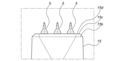
- FIG. 1 is a diagram showing a first embodiment of the present invention, and is a side view of a microneedle unit.
- FIG. 6 is an enlarged side view of a portion VI in FIG. 5 , showing the first embodiment of the present invention.
- FIG. 1 is a diagram showing a first embodiment of the present invention, and is a front view of a microneedle.
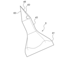
- FIG. 1 is a perspective view of a microneedle according to a first embodiment of the present invention.
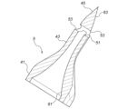
- FIG. 1 is a diagram showing a first embodiment of the present invention, and is a longitudinal sectional view of a microneedle.
- FIG. 1 is a diagram showing a first embodiment of the present invention, and is a longitudinal sectional view of a microneedle.
- 11(a) is a perspective view showing a state in which a slide pin is inserted
- FIG. 11(b) is a perspective view showing a state in which a pair of slide cores are brought close to each other, and
- FIG. 11(c) is a perspective view showing a state in which a core pin has emerged and is abutting against the slide pin.
- 12(a) is a perspective view showing the state after resin has been filled
- FIG. 12(b) is a perspective view showing the state after the core pin has been retracted
- FIG. 12(c) is a perspective view showing the state after the slide pin has been retracted
- FIG. 12(d) is a perspective view showing the state after a pair of slide cores have been separated.
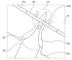
- FIG. 2 is a perspective view of the main part showing a state in which a core pin is pressed against a slide pin and resin is filled, according to the first embodiment of the present invention.
- FIG. 14 is an enlarged view of a portion XIV in FIG.
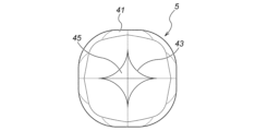
- FIG. 11 is a plan view of a microneedle according to a second embodiment of the present invention.
- FIG. 13 is a side view of a microneedle according to a second embodiment of the present invention.
- FIG. 13 is a plan view of a microneedle according to a third embodiment of the present invention.
- FIG. 13 is a side view of a microneedle according to a third embodiment of the present invention.
- FIG. 13 is a plan view of a microneedle according to a fourth embodiment of the present invention.
- FIG. 13 is a side view of a microneedle according to a fourth embodiment of the present invention.
- FIG. 13 is a plan view of a microneedle according to a fifth embodiment of the present invention.
- FIG. 13 is a side view of a microneedle according to a fifth embodiment of the present invention.
- FIG. 13 is a plan view of a microneedle according to a sixth embodiment of the present invention.
- FIG. 13 is a side view of a microneedle according to a sixth embodiment of the present invention.
- FIG. 13 is a front view of the upper part of the microneedle unit according to the seventh embodiment of the present invention.
- 26A is an electron microscope photograph showing a part of a microneedle unit
- FIG. 26B is an optical microscope photograph showing a microneedle, showing the first embodiment of the present invention.
- 27A and 27B are diagrams showing a first embodiment of the present invention.
- FIG. 13 is a perspective view illustrating the eighth embodiment of the present invention, for explaining the manufacturing process for manufacturing microneedles arranged in multiple rows.
- FIG. 13 is a perspective view illustrating the eighth embodiment of the present invention, for explaining the manufacturing process for manufacturing microneedles arranged in multiple rows.
- FIG. 13 is a perspective view illustrating the eighth embodiment of the present invention, for explaining the manufacturing process for manufacturing microneedles arranged in multiple rows.
- FIG. 13 is a perspective view illustrating the eighth embodiment of the present invention, for explaining the manufacturing process for manufacturing microneedles arranged in multiple rows.
- FIG. 13 is a perspective view illustrating the eighth embodiment of the present invention, for explaining the manufacturing process for manufacturing microneedles arranged in multiple rows.
- FIG. 13 is a perspective view illustrating the eighth embodiment of the present invention, for explaining the manufacturing process for manufacturing microneedles arranged in multiple rows.
- FIG. 13 is a perspective view illustrating the eighth embodiment of the present invention, for explaining the manufacturing process for manufacturing microneedles arranged in multiple rows.
- FIG. 13 is a perspective view illustrating the eighth embodiment of the present invention, for explaining the manufacturing process for manufacturing microneedles arranged in multiple rows.
- FIG. 13 is a perspective view illustrating the eighth embodiment of the present invention, for explaining the manufacturing process for manufacturing microneedles arranged in multiple rows.
- FIG. 13 is a perspective view illustrating the eighth embodiment of the present invention, for explaining the manufacturing process for manufacturing microneedles arranged in multiple rows.
- FIG. 13 is a perspective view illustrating the eighth embodiment of the present invention, for explaining the manufacturing process for manufacturing microneedles arranged in multiple rows.
- FIG. 13 is a perspective view illustrating the eighth embodiment of the present invention, for explaining the manufacturing process for manufacturing microneedles arranged in
- FIG. 13 is a perspective view illustrating the eighth embodiment of the present invention, for explaining the manufacturing process for manufacturing microneedles arranged in multiple rows.
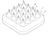
- FIG. 13 is a perspective view of a microneedle unit according to an eighth embodiment of the present invention.
- FIG. 13 is a perspective view of a microneedle unit according to the ninth embodiment of the present invention.
- FIG. 13 is a perspective view showing the relationship between a microneedle unit and a guide pin according to the ninth embodiment of the present invention.
- FIG. 23 is a perspective view of a microneedle unit according to a tenth embodiment of the present invention.
- FIG. 23 is a perspective view showing the relationship between a microneedle unit and a guide pin according to the tenth embodiment of the present invention.
- Fig. 1 is a perspective view of a microneedle unit 1 according to this embodiment, and the microneedle unit 1 is composed of a needle base 3 and a plurality of microneedles 5 (three in this embodiment) provided at the tip of the needle base 3.
- the microneedle unit 1 is made of resin and is molded as a single unit.
- the needle base 3 is composed of a first cylindrical portion 11, a second cylindrical portion 13 that is integral with the tip side of the first circular head portion 11 and has a smaller diameter than the first cylindrical portion 11, and a microneedle base portion 15 that is integral with the tip side of the second cylindrical portion 13.
- the first cylindrical portion 11 has flange portions 21, 21 at the base end thereof, which are 180° opposed to each other. These flange portions 21, 21 act as a prevention against coming off when the microneedle unit 1 is connected to a screw-in type syringe (not shown) (a so-called "Luer lock type” syringe). If the syringe is not a screw-in type (a so-called "Luer taper type”), the flange portions 21, 21 are not necessary.
- the first cylindrical portion 11 has a hollow portion (not shown) inside, into which the tip of the syringe barrel of the syringe is detachably inserted.
- a pair of protrusions 23, 23 protrude from the bottom of the second cylindrical portion 13 to the top of the first cylindrical portion 11.
- the pair of protrusions 23, 23 are perpendicular to the pair of flanges 21, 21 and are provided at positions that are 180° opposed to each other.
- a cap (not shown) is placed on the microneedle 5 side of the microneedle unit 1. When the cap is gripped and screwed into the syringe, the protrusions 23, 23 come into contact with a rib inside the cap and function as a rotation stopper.
- the microneedle base 15 has a tapered shape that gradually reduces in diameter toward the tip. That is, the cross-sectional shape of the lower end 15a of the microneedle base 15 is circular, and the cross-sectional shape of the upper end 15b is elliptical.
- the microneedle base 15 has a tapered shape that linearly connects the circular lower end 15a and the elliptical upper end 15b. Above the upper end 15b there is an elliptical upper end surface 15d via an inclined surface 15c, and the three microneedles 5 already mentioned are integrally provided on this upper end surface 15d.
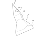
- the microneedle 5 is composed of a base portion 41, a neck portion 43 provided on the base portion 41, and a cone portion 45 provided on the neck portion 43.
- the cone portion 45 has an approximately quadrangular pyramid shape.
- the base portion 41 has a cross-sectional shape of a square with four arc-shaped corners in a range of a specified height from the lowest end. It does not necessarily have to be a square, and can be a circle, etc. The diameter is tapered from the top of the specified height range to the lowest end of the neck portion 43.
- the neck portion 43 also has a cross-sectional shape of a square with four arc-shaped corners, and the square is offset by 45° from the square of the base portion 41.
- a horizontal hole 51 is provided at the bottom of the cone portion 45, and this horizontal hole 51 is penetrating, with both end openings serving as drug solution discharge outlets 53, 53.
- a vertical hole 61 is formed inside the base portion 41 and the neck portion 43 as a drug flow path, and this vertical hole 61 is formed so as to gradually narrow in the range from the base portion 41 to the neck portion 43.
- the cone section 45 has a square cross section and has edge sections 63, 63, 63, 63 along four orthogonal directions.
- the horizontal hole 51 already described is provided on the ridge of the cone section 45, i.e., on a line connecting a pair of opposing edge sections 63, 63 of the four edge sections 63, 63, 63, 63, and both ends serve as the drug solution discharge ports 53, 53.
- the lower parts of the edge sections 63, 63, 63, 63 are formed in an outwardly convex arc shape.
- the length of the microneedle 5 is preferably 0.2 to 2.0 mm, more preferably 0.5 to 1.5 mm, in terms of puncture performance, moldability, drug permeability, etc.
- the needle thickness of the microneedle 5 is preferably 0.05 to 0.3 mm, more preferably 0.1 to 0.25 mm, in terms of strength, skin damage, moldability, etc.
- the size of the vertical hole 61 and horizontal hole 51 is preferably 0.03 to 0.2 mm in diameter, more preferably 0.05 to 0.1 mm.
- the pitch of the microneedle 5 is preferably 0.5 to 3.0 mm.
- the microneedle unit 1 having the above configuration is manufactured by a microneedle manufacturing apparatus 71 shown in Fig. 11.
- a pair of slide cores 73, 73 are arranged so as to be movable toward and away from each other in a horizontal direction perpendicular to the axial direction of the microneedle 5, and a slide pin drive mechanism and other mechanical parts (not shown) are also provided.
- the slide cores 73, 73 are arranged in a size that allows the needle base 3 and the microneedle 5 to be integrally molded. 11 and 12, one slide core 73 is shown by a solid line, and the other slide core 73 is shown by a virtual line.
- a core nest 81 is disposed between the pair of slide cores 73, 73, and a plurality of (three in this embodiment) core pins 83, 83, 83 are provided at the upper end of the core nest 81 so that they can be projected and retracted.
- the upper end of the core pin 83 forms an engagement recess 83a, and the cross-sectional shape of the engagement recess 83a is semicircular.
- the pair of slide cores 73, 73 are disposed so that they can be separated from each other with the core nest 81 in between.
- the core nest 81 is also disposed in a size that allows the needle hub 3 and the microneedle 5 to be integrally molded.
- the slide core 73 is provided with a cavity 73a for molding the microneedle 5 and a cavity 73b for molding the needle base 3.
- a slide pin 85 is disposed between the pair of slide cores 73, 73 on the core insert 81 so that it can be moved in and out by the slide pin drive mechanism.
- the slide cores 73, 73 are formed with recesses 73c, 73c into which the slide pin 85 fits.
- the slide pin 85 has a circular cross-sectional shape.
- a microneedle manufacturing method using the microneedle manufacturing apparatus 71 will be described below.
- 11A the pair of slide cores 73, 73 are separated from each other, and the three core pins 83, 83, 83 are retracted into the core insert 81.
- a slide pin 85 appears between the pair of slide cores 73, 73 as indicated by the arrow a by the slide pin drive mechanism.
- the pair of slide cores 73, 73 are brought close together as indicated by arrow b to clamp the slide pin 85 and surround the core insert 81 with a gap remaining.
- the slide pin 85 is held by the recesses 73c, 73c of the pair of slide cores 73, 73, ensuring its rigidity and preventing bending.
- the core insert 81 is clamped by the cavities 73b, 73b of the pair of slide cores 73, 73 with a gap of a specified thickness remaining.
- resin is injected from the molding machine.
- resin 87 flows into the gap between the cavity 73b and the core insert 81.
- resin 87 flows toward the tip, and forms the vertical hole 61 by flowing into the gap between the core pins 83, 83, 83 and the cavity 73a.
- resin flows into the gap between the slide pin 83 and the cavity 73a, forming the horizontal hole 51, and finally the resin reaches the tip and the injection process is completed.
- the core pins 83, 83, 83 are retracted into the uncored insert 81 as shown in FIG. 12(b).
- the pair of slide cores 73, 73 are separated as indicated by arrow d to remove the molded product, the microneedle unit 1 according to this embodiment.
- FIG. 13 is an enlarged cross-sectional view showing the state of resin filling
- FIG. 14 is a further enlarged cross-sectional view showing part XIV of FIG. 13.
- the slide pin 85 is held by the recesses 73c, 73c of the pair of slide cores 73, 73, ensuring its rigidity.
- resin 87 is pressurized and filled with a predetermined molding pressure.
- the core pin 83 is pressed against the slide pin 85, so it can resist the molding pressure, and neither the core pin 83 nor the slide pin 85 are displaced or deformed.
- the occurrence of burrs at the contact portion between the slide pin 85 and the core pin 83 can be suppressed.
- the upper part of the core pin 83 is a fitting recess 83a with a semicircular cross section to match the outer diameter of the slide pin 85, but this is not limited to this, and other modifications are also possible, such as a V-shape, flat surfaces, or other shapes. It is also possible to increase adhesion by plating or coating the surface of the pin.
- the microneedle 5 having the vertical hole 61 as a drug solution flow path and the horizontal hole 51 connected thereto as a drug solution discharge port in a penetrating state can be easily manufactured by integral molding. This is because a pair of slide cores 73, 73 are arranged so as to be able to come into contact with and separate from each other, a core insert 81 having a retractable core pin 83 is arranged between them, and a slide pin 85 is further arranged so as to be able to retract in order to form the horizontal hole 51.
- the slide pin 85 is clamped between the recesses 73c, 73c of the pair of slide cores 73, 73, its rigidity is guaranteed and the slide pin 85 will not shift in position or deform due to the pressure applied when filling the resin 87, so that the horizontal hole 51 can be molded with high precision and the occurrence of burrs can be eliminated.
- both sides immediately adjacent to the recess 73b forming the microneedle 5 are strongly supported at an extremely short distance like a double-supported beam, thereby further increasing the rigidity.
- the core pin 83 is brought into close contact with the slide pin 85, this also makes it possible to prevent the slide pin 85 from shifting in position or deforming, and the microneedle 5 can be molded with high precision.
- the cross-sectional shape of the fitting recess 83a of the core pin 83 is semicircular, which matches the outer periphery of the circular cross-sectional shape of the slide pin 85, and therefore the above-mentioned effect is enhanced. Furthermore, since the position of the core pin 83 itself is maintained, the core pin 83 does not shift position or deform during molding, and the microneedle 5 can be molded with high precision.
- the core pin 83 has a fitting recess 83a having a semicircular cross section at its tip, and the fitting recess 83a matches the outer shape of the slide pin 85, so that the above-mentioned effect is even greater.
- the pair of slide cores 73, 73 are set to a size that allows the microneedle 5 and the needle base 3 to be integrally molded
- the core insert 81 is also set to a size that allows the microneedle 5 and the needle base 3 to be integrally molded, so that it is possible to easily mold the microneedle unit 1 in which the microneedle 5 and the needle base 3 are integrated. This eliminates the need to prepare a separate needle base 3 as a separate part. Furthermore, because it is molded as a single piece, it is completely airtight compared to separate parts. Furthermore, the microneedles 5 are not bonded but are integrally molded, and therefore have high mechanical strength.
- a pyramidal portion 45 having a quadrangular pyramid shape and four edge portions 63 are provided at the tip, so that the skin can be sharply cut and punctured. Furthermore, since the lower portion of the edge portion 63 is rounded, the skin is not damaged when the needle is removed from the skin after puncturing. Furthermore, since the cross-sectional shape of the horizontal hole 51 is circular, resistance during injection of the liquid medicine is small. Further, a neck portion 43 is provided below the cone portion 45, and this neck portion 43 is in close contact with the skin when the needle is punctured, so that leakage of the injected medicinal liquid can be prevented.
- the base portion 41 is provided below the neck portion 43 and the space between them is in an arc shape, the mechanical strength of the microneedle 5 can be increased. Furthermore, the base portion 41 tensions the skin when puncturing, making it easier to puncture and enabling the puncture depth to be constant. Furthermore, since the vertical hole 61 is formed so as to be gradually narrowed from the bottom to the top, the drug solution can be efficiently injected.
- the tip portion is a cone portion 91
- the cross-sectional shape of the neck portion 43 is a circle.
- the other configurations are the same as those of the first embodiment, and the same parts in the drawings are given the same reference numerals and their explanation is omitted. Therefore, the same effects as those of the first embodiment can be achieved.
- a fifth embodiment of the present invention will be described with reference to Figures 21 and 22.
- a cone portion 93 is provided instead of the tapered portion and neck portion in the first embodiment.
- the other configurations are the same as those of the first embodiment, and the same parts in the drawings are given the same reference numerals and their explanation is omitted. Therefore, the same effects as those of the first embodiment can be achieved.
- the tip is thinner and sharper, making it easier to pierce the skin and reducing damage to the skin.
- each side of the quadrangular pyramid portion 45 in the first embodiment is formed concave, and each side of the neck portion 43 is also formed concave.
- the other configurations are the same as those of the first embodiment, and the same parts in the drawings are given the same reference numerals and their explanation is omitted. Therefore, the same effects as those of the first embodiment can be achieved.
- the seventh embodiment of the present invention will be described with reference to FIG. 25.
- the horizontal holes 51 are provided in a straight line for the three microneedles 5, 5, 5, and are molded using one slide pin 85.
- the horizontal holes 51 are provided for the three microneedles 5, 5, 5, and are oriented in a direction parallel to each other.
- one slide pin 85 and one core pin 83 are arranged for each of the three microneedles 5, 5, 5 (a total of three slide pins 85 and three core pins 83), and the same operation as in the first embodiment is performed for each of them.
- Other configurations are the same as those in the first to sixth embodiments, and the same parts in the drawings are given the same reference numerals and their explanation is omitted.
- FIG. 26( a ) is an electron microscope photograph showing a portion of three microneedles 5 , 5 , 5 of an actually produced microneedle unit 1
- FIG. 26( b ) is an optical microscope photograph showing one microneedle 5
- FIG. 27( a ) is a photograph showing the manufactured microneedle unit 1 attached to a Luer lock syringe 101
- FIG. 27( b ) is a microscope photograph showing water 103 being uniformly discharged from the lateral hole 51 .
- the material was polyglycolic acid (PGA), and the molding conditions were: mold temperature 120° C., resin temperature 240° C., resin pressure 110 MPa, mold clamping force 10 t, and approximately 40 s cycle. It was possible to integrally mold a microneedle unit 1 having a clean through-hole 51 of ⁇ 80 ⁇ m. The tip of the microneedle 5 and the edge of the quadrangular pyramid are formed sharply.
- the needle pitch is 1.3 mm
- the needle length (effective puncture length) is 0.65 mm
- the needle width is 0.22 mm.
- a pair of slide cores 73, 73 are arranged in the microneedle manufacturing apparatus 71 so that they can be brought into contact with each other in a direction perpendicular to the axial direction of the microneedle (horizontal direction in the first embodiment), but in the eighth embodiment, a cabinet nest upper plate 103 and a cabinet nest lower plate 105, which correspond to a pair of slide cores, are arranged in the microneedle manufacturing apparatus 101 so that they can be brought into contact with each other in the axial direction of the microneedle (vertical direction in this embodiment), and a core nest 107 is arranged below the cabinet nest lower plate 105 so that it can be raised and lowered in the vertical direction. This will be described in detail below.
- the cross-sectional shape of the recesses 111 for slide pins is a downward-facing semicircle.
- the cavity insert lower plate 105 has a cavity 113 formed therein, and also has a plurality of (four in this embodiment) slide pin recesses 115 formed therein.
- the cavity 113 is formed of a base cavity 113a corresponding to the base 3' of the microneedle unit 1', and 16 microneedle cavities 113b corresponding to a total of 16 microneedles 5 (four in four rows).
- the cross-sectional shape of the slide pin recesses 115 is an upward-facing semicircle.
- slide pins 121 are arranged so that they can be extended and retracted horizontally, and the four slide pins 121 are clamped by the slide pin recesses 111 and 115.
- the slide pins 121 are driven by a slide pin drive device 123.
- the core insert 107 has a protruding portion 131 for forming the base 3' of the microneedle 1, and this protruding portion 131 has 16 through holes 133 drilled therein, corresponding to a total of 16 microneedles 5, arranged in 4 rows x 4 columns. As shown in FIG. 32, a core pin 141 is disposed so as to pass through each of the 16 through holes 133 and be capable of ascending and descending.
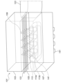
- FIG. 28 shows the state before operation where the slide pin 121, the core pin 131, and the resin are not inserted.
- the cabinet insert upper plate 103 is raised in order to insert the slide pin 121.
- the slide pin 121 is inserted between the cabinet insert upper plate 103 and the cabinet insert lower plate 105.
- the cabinet nest upper plate 103 is lowered so that the slide pin 121 is sandwiched between the cabinet nest upper plate 103 and the cabinet nest lower plate 105 .
- the core pin 131 is raised and the fitting recess at the tip of the core pin 123 is fitted into the slide pin 121. This positions the slide pin 121 and prevents it from shifting or deforming due to pressure applied during resin filling.
- resin 151 is injected to fill the cavity 109 of the cavity insert upper plate 103, between the cavity 113 of the cavity insert lower plate 105 and the protrusion 131 of the core insert 107, and between the cavity 113 of the cavity insert lower plate 105 and the core pin 141.
- the core pin 141 is retracted.
- the slide pin 121 is retracted.
- the core insert 107 is lowered to expose and remove the molded microneedle unit 1'.
- the microneedle unit 1' has a configuration as shown in Figure 37.
- the base 3 of the microneedle unit 1' is circular in plan view, and multiple microneedles 5 (10 in this embodiment) are arranged circumferentially.
- the horizontal holes 51 of each microneedle 5 are oriented in the same direction, and as shown in Figure 39, they are formed using five slide pins 121.
- the base 3' of the microneedle unit 1' is circular in plan view, and multiple microneedles 5 (six in this embodiment) are arranged in pairs along the radial direction at 120° positions.
- the horizontal holes 51 of each microneedle 5 are oriented in the radial direction, and are formed using three slide pins 121, as shown in Figure 41.
- the present invention is not limited to the first to tenth embodiments.
- an example has been described in which three microneedles are molded in a row, but the number of microneedles is not limited to three, and may be one, two, four or more.
- the microneedles are arranged in multiple rows, and a square array, a circular array, and a radial array have been given as examples, but the present invention is not limited to these, and other arrangements such as a staggered arrangement are also contemplated.
- the direction of the slide pin does not necessarily have to be one direction, but it may be inserted from a plurality of directions and the direction of the resulting horizontal hole may be adjusted.
- the microneedle is disposed in the center in the left-right direction in Fig. 5, but it may be offset to either the left or right side, which makes it easier to perform oblique puncture.
- the cross-sectional shape of the horizontal hole is circular, but this is not limited to this and may be rectangular or another shape.
- the position of the horizontal hole may be, for example, in the neck portion 43 in FIG.
- the horizontal holes are provided on the ridges of the quadrangular pyramid, but this is not limiting, and a configuration in which the horizontal holes are provided on a plane between the ridges is also possible.
- the configurations shown in the drawings are merely examples.
- the present invention relates to a microneedle manufacturing method, a microneedle, and a microneedle unit, and in particular to a method that is devised to easily manufacture microneedles that have a penetrating horizontal hole that serves as a drug solution discharge port, and is suitable for manufacturing microneedles for vaccine injections, for example.
Landscapes
- Health & Medical Sciences (AREA)
- Engineering & Computer Science (AREA)
- Dermatology (AREA)
- Medical Informatics (AREA)
- Anesthesiology (AREA)
- Biomedical Technology (AREA)
- Heart & Thoracic Surgery (AREA)
- Hematology (AREA)
- Life Sciences & Earth Sciences (AREA)
- Animal Behavior & Ethology (AREA)
- General Health & Medical Sciences (AREA)
- Public Health (AREA)
- Veterinary Medicine (AREA)
- Media Introduction/Drainage Providing Device (AREA)
Priority Applications (1)
| Application Number | Priority Date | Filing Date | Title |
|---|---|---|---|
| JP2025520562A JPWO2024237204A1 (https=) | 2023-05-12 | 2024-05-10 |
Applications Claiming Priority (2)
| Application Number | Priority Date | Filing Date | Title |
|---|---|---|---|
| JP2023079322 | 2023-05-12 | ||
| JP2023-079322 | 2023-05-12 |
Publications (1)
| Publication Number | Publication Date |
|---|---|
| WO2024237204A1 true WO2024237204A1 (ja) | 2024-11-21 |
Family
ID=93519702
Family Applications (1)
| Application Number | Title | Priority Date | Filing Date |
|---|---|---|---|
| PCT/JP2024/017445 Ceased WO2024237204A1 (ja) | 2023-05-12 | 2024-05-10 | マイクロニードル製造方法とマイクロニードルとマイクロニードルユニット |
Country Status (2)
| Country | Link |
|---|---|
| JP (1) | JPWO2024237204A1 (https=) |
| WO (1) | WO2024237204A1 (https=) |
Citations (9)
| Publication number | Priority date | Publication date | Assignee | Title |
|---|---|---|---|---|
| JP2010502267A (ja) * | 2006-08-28 | 2010-01-28 | エージェンシー・フォー・サイエンス・テクノロジー・アンド・リサーチ | マイクロニードルおよびマイクロニードルの製造方法 |
| CN101856538A (zh) * | 2009-04-09 | 2010-10-13 | 香港理工大学 | 微针阵列、制造该微针阵列的模铸方法及所使用的模具 |
| JP2012509106A (ja) * | 2008-11-18 | 2012-04-19 | スリーエム イノベイティブ プロパティズ カンパニー | 中空のマイクロニードルアレイ及び方法 |
| JP2014519344A (ja) * | 2011-03-18 | 2014-08-14 | ユニヴェルシテ リブル ドゥ ブリュッセル | 人間または動物の体の膜に穴をあけるための装置 |
| JP2016524986A (ja) * | 2013-07-16 | 2016-08-22 | スリーエム イノベイティブ プロパティズ カンパニー | 斜角開口部を有する中空マイクロニードル |
| WO2018181700A1 (ja) * | 2017-03-31 | 2018-10-04 | 凸版印刷株式会社 | 経皮投与デバイス |
| WO2018181639A1 (ja) * | 2017-03-31 | 2018-10-04 | Asti株式会社 | マイクロニードルアレイとマイクロニードルアレイ製造方法 |
| WO2018198675A1 (ja) * | 2017-04-27 | 2018-11-01 | シンクランド株式会社 | マイクロニードルの製造方法 |
| WO2019053977A1 (ja) * | 2017-09-13 | 2019-03-21 | 花王株式会社 | 中空突起具の製造方法、中空突起具の製造装置、及び中空突起具 |
-
2024
- 2024-05-10 JP JP2025520562A patent/JPWO2024237204A1/ja active Pending
- 2024-05-10 WO PCT/JP2024/017445 patent/WO2024237204A1/ja not_active Ceased
Patent Citations (9)
| Publication number | Priority date | Publication date | Assignee | Title |
|---|---|---|---|---|
| JP2010502267A (ja) * | 2006-08-28 | 2010-01-28 | エージェンシー・フォー・サイエンス・テクノロジー・アンド・リサーチ | マイクロニードルおよびマイクロニードルの製造方法 |
| JP2012509106A (ja) * | 2008-11-18 | 2012-04-19 | スリーエム イノベイティブ プロパティズ カンパニー | 中空のマイクロニードルアレイ及び方法 |
| CN101856538A (zh) * | 2009-04-09 | 2010-10-13 | 香港理工大学 | 微针阵列、制造该微针阵列的模铸方法及所使用的模具 |
| JP2014519344A (ja) * | 2011-03-18 | 2014-08-14 | ユニヴェルシテ リブル ドゥ ブリュッセル | 人間または動物の体の膜に穴をあけるための装置 |
| JP2016524986A (ja) * | 2013-07-16 | 2016-08-22 | スリーエム イノベイティブ プロパティズ カンパニー | 斜角開口部を有する中空マイクロニードル |
| WO2018181700A1 (ja) * | 2017-03-31 | 2018-10-04 | 凸版印刷株式会社 | 経皮投与デバイス |
| WO2018181639A1 (ja) * | 2017-03-31 | 2018-10-04 | Asti株式会社 | マイクロニードルアレイとマイクロニードルアレイ製造方法 |
| WO2018198675A1 (ja) * | 2017-04-27 | 2018-11-01 | シンクランド株式会社 | マイクロニードルの製造方法 |
| WO2019053977A1 (ja) * | 2017-09-13 | 2019-03-21 | 花王株式会社 | 中空突起具の製造方法、中空突起具の製造装置、及び中空突起具 |
Also Published As
| Publication number | Publication date |
|---|---|
| JPWO2024237204A1 (https=) | 2024-11-21 |
Similar Documents
| Publication | Publication Date | Title |
|---|---|---|
| CN101856538B (zh) | 微针阵列、制造该微针阵列的模铸方法及所使用的模具 | |
| EP2416835B1 (en) | Methods of making hollow microneedle arrays | |
| US10155334B2 (en) | Molding thermotropic liquid crystalline polymers and articles made therefrom | |
| US9533131B2 (en) | Hollow needlelike object and method for manufacturing hollow needlelike object | |
| US10603476B2 (en) | Microneedle | |
| JP6298822B2 (ja) | 針付きシリンジ及びその射出成型用金型 | |
| US7670538B2 (en) | Cannula casting mould and casting method | |
| JP5845808B2 (ja) | マイクロニードルデバイスおよびその製造方法 | |
| AU2002311184B2 (en) | Method of manufacturing outer tube of injector | |
| US20090326415A1 (en) | Microneedles and methods for fabricating microneedles | |
| JP7051815B2 (ja) | マイクロニードルアレイとマイクロニードルアレイ製造方法 | |
| WO2005082596A1 (en) | Method of molding for microneedle arrays | |
| JP4779084B2 (ja) | マイクロニードルおよびその製造方法と金型 | |
| US20090318833A1 (en) | Needle Structures and Methods for Fabricating Needle Structures | |
| JP2014519344A (ja) | 人間または動物の体の膜に穴をあけるための装置 | |
| JPWO2017135060A1 (ja) | マイクロニードル | |
| WO2024237204A1 (ja) | マイクロニードル製造方法とマイクロニードルとマイクロニードルユニット | |
| JP2020131704A (ja) | マイクロニードルの成形方法及び成形金型 | |
| JP6147230B2 (ja) | マイクロニードルアレイとマイクロニードルアレイ製造方法 | |
| JP2013166363A (ja) | 微細針チップ射出成形用金型及びその微細針チップを射出成形する方法 | |
| JP7230377B2 (ja) | マイクロニードル | |
| CN212400196U (zh) | 用于制备微针芯片的组合式型芯、注射成型模具 |
Legal Events
| Date | Code | Title | Description |
|---|---|---|---|
| 121 | Ep: the epo has been informed by wipo that ep was designated in this application |
Ref document number: 24807156 Country of ref document: EP Kind code of ref document: A1 |
|
| ENP | Entry into the national phase |
Ref document number: 2025520562 Country of ref document: JP Kind code of ref document: A |
|
| NENP | Non-entry into the national phase |
Ref country code: DE |