WO2024236742A1 - 冷凍サイクル装置 - Google Patents
冷凍サイクル装置 Download PDFInfo
- Publication number
- WO2024236742A1 WO2024236742A1 PCT/JP2023/018316 JP2023018316W WO2024236742A1 WO 2024236742 A1 WO2024236742 A1 WO 2024236742A1 JP 2023018316 W JP2023018316 W JP 2023018316W WO 2024236742 A1 WO2024236742 A1 WO 2024236742A1
- Authority
- WO
- WIPO (PCT)
- Prior art keywords
- refrigerant
- heat exchanger
- refrigeration cycle
- temperature
- cycle device
- Prior art date
- Legal status (The legal status is an assumption and is not a legal conclusion. Google has not performed a legal analysis and makes no representation as to the accuracy of the status listed.)
- Ceased
Links
Images






Classifications
-
- F—MECHANICAL ENGINEERING; LIGHTING; HEATING; WEAPONS; BLASTING
- F25—REFRIGERATION OR COOLING; COMBINED HEATING AND REFRIGERATION SYSTEMS; HEAT PUMP SYSTEMS; MANUFACTURE OR STORAGE OF ICE; LIQUEFACTION SOLIDIFICATION OF GASES
- F25B—REFRIGERATION MACHINES, PLANTS OR SYSTEMS; COMBINED HEATING AND REFRIGERATION SYSTEMS; HEAT PUMP SYSTEMS
- F25B7/00—Compression machines, plants or systems, with cascade operation, i.e. with two or more circuits, the heat from the condenser of one circuit being absorbed by the evaporator of the next circuit
-
- F—MECHANICAL ENGINEERING; LIGHTING; HEATING; WEAPONS; BLASTING
- F25—REFRIGERATION OR COOLING; COMBINED HEATING AND REFRIGERATION SYSTEMS; HEAT PUMP SYSTEMS; MANUFACTURE OR STORAGE OF ICE; LIQUEFACTION SOLIDIFICATION OF GASES
- F25B—REFRIGERATION MACHINES, PLANTS OR SYSTEMS; COMBINED HEATING AND REFRIGERATION SYSTEMS; HEAT PUMP SYSTEMS
- F25B40/00—Subcoolers, desuperheaters or superheaters
- F25B40/02—Subcoolers
-
- F—MECHANICAL ENGINEERING; LIGHTING; HEATING; WEAPONS; BLASTING
- F25—REFRIGERATION OR COOLING; COMBINED HEATING AND REFRIGERATION SYSTEMS; HEAT PUMP SYSTEMS; MANUFACTURE OR STORAGE OF ICE; LIQUEFACTION SOLIDIFICATION OF GASES
- F25B—REFRIGERATION MACHINES, PLANTS OR SYSTEMS; COMBINED HEATING AND REFRIGERATION SYSTEMS; HEAT PUMP SYSTEMS
- F25B40/00—Subcoolers, desuperheaters or superheaters
- F25B40/06—Superheaters
-
- F—MECHANICAL ENGINEERING; LIGHTING; HEATING; WEAPONS; BLASTING
- F25—REFRIGERATION OR COOLING; COMBINED HEATING AND REFRIGERATION SYSTEMS; HEAT PUMP SYSTEMS; MANUFACTURE OR STORAGE OF ICE; LIQUEFACTION SOLIDIFICATION OF GASES
- F25B—REFRIGERATION MACHINES, PLANTS OR SYSTEMS; COMBINED HEATING AND REFRIGERATION SYSTEMS; HEAT PUMP SYSTEMS
- F25B49/00—Arrangement or mounting of control or safety devices
- F25B49/02—Arrangement or mounting of control or safety devices for compression type machines, plants or systems
- F25B49/022—Compressor control arrangements
-
- F—MECHANICAL ENGINEERING; LIGHTING; HEATING; WEAPONS; BLASTING
- F25—REFRIGERATION OR COOLING; COMBINED HEATING AND REFRIGERATION SYSTEMS; HEAT PUMP SYSTEMS; MANUFACTURE OR STORAGE OF ICE; LIQUEFACTION SOLIDIFICATION OF GASES
- F25B—REFRIGERATION MACHINES, PLANTS OR SYSTEMS; COMBINED HEATING AND REFRIGERATION SYSTEMS; HEAT PUMP SYSTEMS
- F25B9/00—Compression machines, plants or systems, in which the refrigerant is air or other gas of low boiling point
- F25B9/002—Compression machines, plants or systems, in which the refrigerant is air or other gas of low boiling point characterised by the refrigerant
- F25B9/008—Compression machines, plants or systems, in which the refrigerant is air or other gas of low boiling point characterised by the refrigerant the refrigerant being carbon dioxide
-
- F—MECHANICAL ENGINEERING; LIGHTING; HEATING; WEAPONS; BLASTING
- F25—REFRIGERATION OR COOLING; COMBINED HEATING AND REFRIGERATION SYSTEMS; HEAT PUMP SYSTEMS; MANUFACTURE OR STORAGE OF ICE; LIQUEFACTION SOLIDIFICATION OF GASES
- F25B—REFRIGERATION MACHINES, PLANTS OR SYSTEMS; COMBINED HEATING AND REFRIGERATION SYSTEMS; HEAT PUMP SYSTEMS
- F25B2400/00—Component parts or details not otherwise provided for in this subclass
- F25B2400/04—Refrigeration circuit bypassing means
- F25B2400/0419—Refrigeration circuit bypassing means for superheaters
-
- F—MECHANICAL ENGINEERING; LIGHTING; HEATING; WEAPONS; BLASTING
- F25—REFRIGERATION OR COOLING; COMBINED HEATING AND REFRIGERATION SYSTEMS; HEAT PUMP SYSTEMS; MANUFACTURE OR STORAGE OF ICE; LIQUEFACTION SOLIDIFICATION OF GASES
- F25B—REFRIGERATION MACHINES, PLANTS OR SYSTEMS; COMBINED HEATING AND REFRIGERATION SYSTEMS; HEAT PUMP SYSTEMS
- F25B2500/00—Problems to be solved
- F25B2500/07—Exceeding a certain pressure value in a refrigeration component or cycle
-
- F—MECHANICAL ENGINEERING; LIGHTING; HEATING; WEAPONS; BLASTING
- F25—REFRIGERATION OR COOLING; COMBINED HEATING AND REFRIGERATION SYSTEMS; HEAT PUMP SYSTEMS; MANUFACTURE OR STORAGE OF ICE; LIQUEFACTION SOLIDIFICATION OF GASES
- F25B—REFRIGERATION MACHINES, PLANTS OR SYSTEMS; COMBINED HEATING AND REFRIGERATION SYSTEMS; HEAT PUMP SYSTEMS
- F25B2600/00—Control issues
- F25B2600/02—Compressor control
- F25B2600/025—Compressor control by controlling speed
- F25B2600/0253—Compressor control by controlling speed with variable speed
-
- F—MECHANICAL ENGINEERING; LIGHTING; HEATING; WEAPONS; BLASTING
- F25—REFRIGERATION OR COOLING; COMBINED HEATING AND REFRIGERATION SYSTEMS; HEAT PUMP SYSTEMS; MANUFACTURE OR STORAGE OF ICE; LIQUEFACTION SOLIDIFICATION OF GASES
- F25B—REFRIGERATION MACHINES, PLANTS OR SYSTEMS; COMBINED HEATING AND REFRIGERATION SYSTEMS; HEAT PUMP SYSTEMS
- F25B2600/00—Control issues
- F25B2600/25—Control of valves
- F25B2600/2501—Bypass valves
-
- F—MECHANICAL ENGINEERING; LIGHTING; HEATING; WEAPONS; BLASTING
- F25—REFRIGERATION OR COOLING; COMBINED HEATING AND REFRIGERATION SYSTEMS; HEAT PUMP SYSTEMS; MANUFACTURE OR STORAGE OF ICE; LIQUEFACTION SOLIDIFICATION OF GASES
- F25B—REFRIGERATION MACHINES, PLANTS OR SYSTEMS; COMBINED HEATING AND REFRIGERATION SYSTEMS; HEAT PUMP SYSTEMS
- F25B2700/00—Sensing or detecting of parameters; Sensors therefor
- F25B2700/19—Pressures
- F25B2700/193—Pressures of the compressor
- F25B2700/1933—Suction pressures
-
- F—MECHANICAL ENGINEERING; LIGHTING; HEATING; WEAPONS; BLASTING
- F25—REFRIGERATION OR COOLING; COMBINED HEATING AND REFRIGERATION SYSTEMS; HEAT PUMP SYSTEMS; MANUFACTURE OR STORAGE OF ICE; LIQUEFACTION SOLIDIFICATION OF GASES
- F25B—REFRIGERATION MACHINES, PLANTS OR SYSTEMS; COMBINED HEATING AND REFRIGERATION SYSTEMS; HEAT PUMP SYSTEMS
- F25B2700/00—Sensing or detecting of parameters; Sensors therefor
- F25B2700/19—Pressures
- F25B2700/195—Pressures of the condenser
-
- F—MECHANICAL ENGINEERING; LIGHTING; HEATING; WEAPONS; BLASTING
- F25—REFRIGERATION OR COOLING; COMBINED HEATING AND REFRIGERATION SYSTEMS; HEAT PUMP SYSTEMS; MANUFACTURE OR STORAGE OF ICE; LIQUEFACTION SOLIDIFICATION OF GASES
- F25B—REFRIGERATION MACHINES, PLANTS OR SYSTEMS; COMBINED HEATING AND REFRIGERATION SYSTEMS; HEAT PUMP SYSTEMS
- F25B2700/00—Sensing or detecting of parameters; Sensors therefor
- F25B2700/19—Pressures
- F25B2700/197—Pressures of the evaporator
-
- F—MECHANICAL ENGINEERING; LIGHTING; HEATING; WEAPONS; BLASTING
- F25—REFRIGERATION OR COOLING; COMBINED HEATING AND REFRIGERATION SYSTEMS; HEAT PUMP SYSTEMS; MANUFACTURE OR STORAGE OF ICE; LIQUEFACTION SOLIDIFICATION OF GASES
- F25B—REFRIGERATION MACHINES, PLANTS OR SYSTEMS; COMBINED HEATING AND REFRIGERATION SYSTEMS; HEAT PUMP SYSTEMS
- F25B2700/00—Sensing or detecting of parameters; Sensors therefor
- F25B2700/21—Temperatures
- F25B2700/2104—Temperatures of an indoor room or compartment
-
- F—MECHANICAL ENGINEERING; LIGHTING; HEATING; WEAPONS; BLASTING
- F25—REFRIGERATION OR COOLING; COMBINED HEATING AND REFRIGERATION SYSTEMS; HEAT PUMP SYSTEMS; MANUFACTURE OR STORAGE OF ICE; LIQUEFACTION SOLIDIFICATION OF GASES
- F25B—REFRIGERATION MACHINES, PLANTS OR SYSTEMS; COMBINED HEATING AND REFRIGERATION SYSTEMS; HEAT PUMP SYSTEMS
- F25B2700/00—Sensing or detecting of parameters; Sensors therefor
- F25B2700/21—Temperatures
- F25B2700/2115—Temperatures of a compressor or the drive means therefor
- F25B2700/21151—Temperatures of a compressor or the drive means therefor at the suction side of the compressor
-
- F—MECHANICAL ENGINEERING; LIGHTING; HEATING; WEAPONS; BLASTING
- F25—REFRIGERATION OR COOLING; COMBINED HEATING AND REFRIGERATION SYSTEMS; HEAT PUMP SYSTEMS; MANUFACTURE OR STORAGE OF ICE; LIQUEFACTION SOLIDIFICATION OF GASES
- F25B—REFRIGERATION MACHINES, PLANTS OR SYSTEMS; COMBINED HEATING AND REFRIGERATION SYSTEMS; HEAT PUMP SYSTEMS
- F25B2700/00—Sensing or detecting of parameters; Sensors therefor
- F25B2700/21—Temperatures
- F25B2700/2115—Temperatures of a compressor or the drive means therefor
- F25B2700/21152—Temperatures of a compressor or the drive means therefor at the discharge side of the compressor
-
- F—MECHANICAL ENGINEERING; LIGHTING; HEATING; WEAPONS; BLASTING
- F25—REFRIGERATION OR COOLING; COMBINED HEATING AND REFRIGERATION SYSTEMS; HEAT PUMP SYSTEMS; MANUFACTURE OR STORAGE OF ICE; LIQUEFACTION SOLIDIFICATION OF GASES
- F25B—REFRIGERATION MACHINES, PLANTS OR SYSTEMS; COMBINED HEATING AND REFRIGERATION SYSTEMS; HEAT PUMP SYSTEMS
- F25B2700/00—Sensing or detecting of parameters; Sensors therefor
- F25B2700/21—Temperatures
- F25B2700/2116—Temperatures of a condenser
- F25B2700/21162—Temperatures of a condenser of the refrigerant at the inlet of the condenser
-
- F—MECHANICAL ENGINEERING; LIGHTING; HEATING; WEAPONS; BLASTING
- F25—REFRIGERATION OR COOLING; COMBINED HEATING AND REFRIGERATION SYSTEMS; HEAT PUMP SYSTEMS; MANUFACTURE OR STORAGE OF ICE; LIQUEFACTION SOLIDIFICATION OF GASES
- F25B—REFRIGERATION MACHINES, PLANTS OR SYSTEMS; COMBINED HEATING AND REFRIGERATION SYSTEMS; HEAT PUMP SYSTEMS
- F25B2700/00—Sensing or detecting of parameters; Sensors therefor
- F25B2700/21—Temperatures
- F25B2700/2116—Temperatures of a condenser
- F25B2700/21163—Temperatures of a condenser of the refrigerant at the outlet of the condenser
Definitions
- This disclosure relates to a refrigeration cycle device.
- a two-stage refrigeration cycle apparatus is used in refrigeration equipment with a relatively low evaporation temperature for use in refrigeration or freezing.
- the two-stage refrigeration cycle apparatus described in Patent Document 1 comprises a primary unit and a secondary unit.
- the primary unit uses a flammable refrigerant such as propane to reduce the Global Warming Potential (GWP).
- GWP Global Warming Potential
- This two-stage refrigeration cycle apparatus also employs a so-called direct expansion type.
- a configuration is considered in which a flammable refrigerant such as propane is used as the refrigerant in the primary unit.
- a flammable refrigerant such as propane is used as the refrigerant in the primary unit.
- the necessary piping length from the expansion valve to the evaporator must be taken into consideration, so there is little freedom in the amount of refrigerant charged, making it difficult to suppress the amount of refrigerant.
- the cascade refrigeration cycle device is equipped with a first refrigerant circuit and a second refrigerant circuit.
- the first refrigerant sealed in the first refrigerant circuit can be water or brine.
- the refrigerant in the first refrigerant circuit is water, the refrigerant may not be usable at temperatures below 0 degrees.
- the refrigerant in the first refrigerant circuit is brine, the viscosity of the brine becomes high in the low temperature range, and the cooling efficiency may deteriorate.
- refrigerant containing carbon dioxide it is possible to use a refrigerant containing carbon dioxide as the refrigerant in the first refrigerant circuit.
- reducing the amount of refrigerant charged in the first refrigerant circuit was not taken into consideration. Therefore, it was difficult to configure a refrigeration cycle device that would operate properly using carbon dioxide as the refrigerant in the first refrigerant circuit.
- the present disclosure has been made to solve the above-mentioned problems, and its purpose is to provide a refrigeration cycle device that can use a refrigerant containing carbon dioxide as the refrigerant for the first refrigerant circuit and that operates appropriately.
- the refrigeration cycle device of the present disclosure cools an object to be cooled using a first refrigerant and a second refrigerant.
- the refrigeration cycle device includes a first refrigerant circuit in which the first refrigerant circulates, a second refrigerant circuit in which the second refrigerant circulates, and a control device that controls the first refrigerant circuit and the second refrigerant circuit.
- the first refrigerant circuit includes a first heat exchanger, a pump, and a second heat exchanger, and is configured to circulate the first refrigerant in this order by operation of the pump.
- the second refrigerant circuit includes a compressor, a third heat exchanger, an expansion valve, and the first heat exchanger, and is configured to circulate the second refrigerant in this order by operation of the compressor.
- the first heat exchanger is configured to exchange heat between the first refrigerant and the second refrigerant.
- the present disclosure provides a refrigeration cycle device that uses carbon dioxide as a refrigerant in the first refrigerant circuit and operates appropriately.
- FIG. 1 is a diagram showing a schematic diagram of an overall configuration of a refrigeration cycle device 1.
- FIG. 1 is a diagram showing a schematic diagram of an overall configuration of a refrigeration cycle device 1A.
- FIG. 4 is a diagram showing an example of a Ph line for a first refrigerant.
- FIG. 2 is a diagram showing a configuration example of a refrigeration cycle device 1B.
- 4 is a flowchart showing a process of the control device.
- FIG. 11 is a diagram illustrating an example of a table showing a correspondence relationship between a type of defrosting operation and a type of supercooling operation. 4 is a flowchart showing a process of the control device.
- 1 is a diagram showing a schematic diagram of an overall configuration of a refrigeration cycle device 1C.
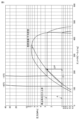
- FIG. 13 is a diagram showing an example of the density D.
- FIG. 1 is a diagram showing a schematic diagram of the overall configuration of a refrigeration cycle device 1 according to the present embodiment.
- the refrigeration cycle device 1 is a two-stage refrigeration cycle device that cools a cooling target using a first refrigerant and a second refrigerant.
- the refrigeration cycle device 1 includes an indoor unit 10, an outdoor unit 20, a first pipe 4, a second pipe 5, and a control device 100.
- the indoor unit 10 and the outdoor unit 20 are connected via the first pipe 4 and the second pipe 5.
- the outdoor unit 20 is installed outdoors.
- the indoor unit 10 is installed in a space to be cooled.
- the space to be cooled is, for example, an "indoor space".
- the indoor space is, for example, a space in which a cooling target is placed, an internal space of a showcase, or the like. This indoor space is also called a "space to be cooled”.
- the refrigeration cycle device 1 includes a first refrigerant circuit C1 in which a first refrigerant is sealed and circulated, and a second refrigerant circuit C2 in which a second refrigerant is sealed and circulated.
- the indoor unit 10 includes a portion of the first refrigerant circuit C1.
- the indoor unit 10 includes a portion of the first refrigerant circuit C1 and the second refrigerant circuit C2.
- the first refrigerant is a refrigerant that has a lower boiling point than the second refrigerant at the same pressure. That is, in the refrigeration cycle device 1, the first refrigerant circulating through the first refrigerant circuit C1 is a low-temperature side refrigerant, and the second refrigerant circulating through the second refrigerant circuit C2 is a high-temperature side refrigerant.
- the first refrigerant sealed in the first refrigerant circuit C1 on the low-temperature side passes through the first pipe 4 and the second pipe 5.
- the first refrigerant a refrigerant whose main component is carbon dioxide, which is non-flammable, has a small temperature drop due to pressure loss, and has a small global warming potential (GWP).
- the first refrigerant is, for example, a refrigerant composed of carbon dioxide, or a mixed refrigerant containing carbon dioxide and other substances.
- carbon dioxide refrigerants such refrigerants and mixed refrigerants are collectively referred to as "carbon dioxide refrigerants”.
- the second refrigerant filled in the second refrigerant circuit C2 on the high temperature side does not pass through the first pipe 4 and the second pipe 5, and even if it leaks, it will not be released directly into the room.
- a refrigerant with a high coefficient of performance (COP) and a relatively small GWP as the second refrigerant.
- propane or a mixed refrigerant containing propane can be used as the second refrigerant.
- the second refrigerant may be a refrigerant other than propane.
- the first refrigerant circuit C1 on the low-temperature side is a latent heat transport system that circulates refrigerant using a liquid pump 32.
- the first refrigerant circuit C1 mainly comprises a first heat exchanger 61, a liquid tank 31 (receiver), a liquid pump 32, a flow control valve 34, and a second heat exchanger 62.
- the liquid pump 32 corresponds to the "pump" in this disclosure.
- the first refrigerant circuit C1 is configured such that, by operation of the liquid pump 32, the first refrigerant circulates through the first heat exchanger 61, the liquid tank 31, the liquid pump 32, the flow control valve 34, and the second heat exchanger 62 in that order.
- the first heat exchanger 61 has a first passage H1 through which the first refrigerant flows and a second passage H2 through which the second refrigerant flows.
- the first heat exchanger 61 is configured to exchange heat between the first refrigerant flowing through the first passage H1 and the second refrigerant flowing through the second passage H2.
- the first refrigerant condenses through the heat exchange, and the second refrigerant evaporates through the heat exchange. Specifically, in the first heat exchanger 61, the first refrigerant releases heat to the second refrigerant.
- the first heat exchanger 61 is, for example, a cascade condenser, which acts as a condenser in the first refrigerant circuit C1 and as an evaporator in the second refrigerant circuit C2.
- a cascade condenser a plate heat exchanger, a double-tube heat exchanger, or a dry shell-and-tube heat exchanger, etc., may be used.
- the liquid tank 31 is connected to the outlet of the first passage H1 of the first heat exchanger 61 via a pipe connected to the liquid tank 31.
- the liquid tank 31 temporarily stores the first refrigerant therein.
- the liquid tank 31 is not necessarily required.
- the liquid pump 32 draws in the first refrigerant in liquid state stored in the liquid tank 31 and discharges it to the second heat exchanger 62 via the flow control valve 34.
- the intake port of the second heat exchanger 62 is connected to the discharge port of the liquid pump 32 via piping and the flow control valve 34.
- the second heat exchanger 62 acts as an evaporator in the first refrigerant circuit C1.
- the second heat exchanger 62 exchanges heat between the first refrigerant and a heat medium, such as the air surrounding the second heat exchanger 62, and acts as a cooler that cools the heat medium (indoor space).
- the second heat exchanger 62 is disposed in the indoor space.
- a flow rate control valve 34 is disposed between the liquid pump 32 and the second heat exchanger 62.
- the control device 100 can adjust the flow rate of the first refrigerant flowing from the liquid pump 32 to the second heat exchanger 62 by controlling the opening degree of the flow rate control valve 34.
- the flow rate control valve 34 is not necessarily required.
- the exhaust port of the second heat exchanger 62 is connected to the intake port of the first passage H1 of the first heat exchanger 61 via a pipe.
- the second heat exchanger 62 is, for example, a fin-and-tube type heat exchanger having a heat transfer tube and fins.
- the second refrigerant circuit C2 includes a first heat exchanger 61, a compressor 21, a third heat exchanger 63, and an expansion valve 23.
- the second refrigerant circuit C2 is configured such that, by operation of the compressor 21, the second refrigerant circulates through the compressor 21, the third heat exchanger 63, the expansion valve 23, and the first heat exchanger 61 in that order.
- the third heat exchanger 63 acts as a condenser in the second refrigerant circuit C2.
- the third heat exchanger 63 is, for example, a heat exchanger that exchanges heat between the second refrigerant and a heat medium such as the air surrounding the third heat exchanger 63.
- the control device 100 has a CPU (Central Processing Unit) 102, a memory 104, and the like.
- the memory 104 is configured to include, for example, a ROM (Read Only Memory) and a RAM (Random Access Memory), and the like.
- the control device 100 controls each component of the first refrigerant circuit C1 and the second refrigerant circuit C2 (liquid pump 32, flow control valve 34, compressor 21, expansion valve 23, etc.) according to, for example, a program stored in the ROM. This control is not limited to processing by software, and can also be processed by dedicated hardware (electronic circuitry).
- control device 100 When the refrigeration cycle device 1 is in operation, the control device 100 operates the liquid pump 32 of the first refrigerant circuit C1 and the compressor 21 of the second refrigerant circuit C2.
- the compressor 21 When the compressor 21 operates, it compresses and discharges the second refrigerant.
- the discharged second refrigerant flows into the third heat exchanger 63, where it dissipates heat.
- the second refrigerant from which heat has been dissipated is depressurized by the expansion valve 23.
- the depressurized second refrigerant receives heat from the first refrigerant in the first passage H1 in the first heat exchanger 61.
- the second refrigerant evaporates into a gaseous state and is sucked into the compressor 21.
- the first refrigerant in liquid state in the liquid tank 31 flows into the second heat exchanger 62 in the first refrigerant circuit C1.
- the first refrigerant in liquid state that flows into the second heat exchanger 62 evaporates by exchanging heat with a heat medium such as the air surrounding the second heat exchanger 62. This cools the heat medium. If the heat medium is likely to be cooled excessively, the control device 100 reduces the opening of the flow control valve 34 or stops the liquid pump 32 to prevent the first refrigerant from flowing excessively into the second heat exchanger 62, thereby suppressing excessive cooling of the heat medium.
- the first refrigerant in a gaseous state flowing in the first passage H1 exchanges heat with the second refrigerant flowing in the second passage H2 in the first heat exchanger 61 and condenses.
- the second refrigerant in the second passage H2 evaporates.
- the first refrigerant is separated into gas and liquid in the liquid tank 31.
- the first refrigerant in a liquid state is stored in the lower part of the liquid tank 31, and the first refrigerant in a gas state is stored in the upper part of the liquid tank 31.
- a liquid pump 32 is arranged in the indoor unit 10 (first refrigerant circuit C1) instead of a compressor. Therefore, compared to a comparative example of a refrigeration cycle device in which the indoor unit has a compressor, a compressor, an accumulator, an air-cooled condenser, etc. are not required.
- the size of the liquid pump 32 is smaller than the "size of the compressor, accumulator, and air-cooled condenser," the cross-sectional area of the piping in the indoor unit 10 (first refrigerant circuit C1) can be reduced, and as a result, the volume of the piping can be reduced. Therefore, the amount of the first refrigerant sealed in the indoor unit 10 (first refrigerant circuit C1) can be reduced.
- first refrigerant water or brine
- first refrigerant it may not be possible to use the refrigerant at temperatures below 0 degrees.
- first refrigerant is brine
- the viscosity of the brine may increase in the low temperature range, resulting in poor cooling efficiency.
- the carbon dioxide refrigerant is used as the first refrigerant.
- the amount of solvent of the first refrigerant charged in the indoor unit 10 can be reduced. Therefore, the first refrigerant can be carbon dioxide refrigerant. Therefore, unlike a configuration in which the first refrigerant is water, the refrigeration cycle device 1 can circulate the first refrigerant even at temperatures below 0 degrees.
- the refrigeration cycle device 1 using such a first refrigerant has superior thermal characteristics and low viscosity compared to a configuration in which the first refrigerant is brine. Furthermore, generally, carbon dioxide refrigerant is cheaper than brine. In addition, the refrigeration cycle device 1 using such a first refrigerant is less corrosive compared to a configuration in which the first refrigerant is brine, so that workers can easily perform maintenance on the piping of the indoor unit 10.
- the refrigeration cycle device of this embodiment is equipped with at least one temperature sensor and at least one pressure sensor.
- the control device 100 controls the indoor unit 10 and the outdoor unit 20 based on the detection value of the at least one temperature sensor and the detection value of the at least one pressure sensor.
- FIG. 2 is a diagram showing an example of the configuration of the refrigeration cycle apparatus 1A.
- the refrigeration cycle apparatus 1A is an apparatus that adds a temperature sensor and a pressure sensor to the refrigeration cycle apparatus 1.
- the refrigeration cycle apparatus 1A is equipped with temperature sensors 41, 42, 43, 44, 45, 46, 47, 48 and pressure sensors 51, 52, 53, 54.
- the detection values of the temperature sensors 41, 42, 43, 44, 45, 46, 47, 48 and the detection values of the pressure sensors 51, 52, 53, 54 are input to the control device 100.
- the control device controls each of the above-mentioned devices in the refrigeration cycle apparatus 1 based on the input detection values.
- Temperature sensors 41, 42, 43, and 44 are arranged in the outdoor unit 20. Temperature sensors 45, 46, 47, and 48 are arranged in the outdoor unit 20. Pressure sensors 51 and 52 are arranged in the outdoor unit 20. Pressure sensors 53 and 54 are arranged in the indoor unit 10.
- Temperature sensor 41 detects the temperature of the second refrigerant sucked into compressor 21. Temperature sensor 42 detects the temperature of the second refrigerant discharged from compressor 21. Temperature sensor 43 detects the temperature of the air sucked into third heat exchanger 63 (around third heat exchanger 63). Temperature sensor 44 detects the temperature of the second refrigerant on the outlet side of third heat exchanger 63.
- the temperature sensor 45 detects the temperature of the first refrigerant flowing out of the first heat exchanger 61.
- the temperature sensor 46 detects the temperature of the first refrigerant flowing into the first heat exchanger 61.
- the temperature sensor 47 detects the temperature of the space to be cooled.
- the temperature sensor 48 detects the temperature of the first refrigerant on the outlet side of the second heat exchanger 62.
- the pressure sensor 51 detects the pressure of the second refrigerant on the outlet side of the third heat exchanger 63.
- the pressure detected by the pressure sensor 51 corresponds to the high pressure portion of the outdoor unit 20.
- the pressure sensor 52 detects the pressure of the second refrigerant on the outlet side of the second passage H2 of the first heat exchanger 61.
- the pressure detected by the pressure sensor 52 corresponds to the low pressure portion of the outdoor unit 20.
- the pressure sensor 53 detects the pressure (fluid pressure) of the first refrigerant at the outlet of the first passage H1 of the first heat exchanger 61.
- the pressure sensor 54 detects the pressure of the first refrigerant at the outlet side of the second heat exchanger 62.
- the control device 100 controls the compressor 21 based on the detection value of the pressure sensor 52.
- the control device 100 performs feedback control of the operating frequency (rotation speed) of the compressor 21 so that the detection value of the pressure sensor 52 approaches a predetermined target value.
- the compressor 21 is a constant speed compressor, the compressor 21 is operated until the detection value of the pressure sensor 52 reaches the target value, and the compressor 21 is stopped when the detection value of the pressure sensor 52 reaches the target value.
- the control device 100 feedback controls the opening of the expansion valve 23 so that the superheat on the outlet side of the first heat exchanger 61 (hereinafter also referred to as the "first superheat") becomes a target value.
- This first superheat is calculated from the difference between the temperature detected by the temperature sensor 41 and the evaporation temperature (saturation temperature) for the pressure detected by the pressure sensor 52.
- the first refrigerant cooled in the first passage H1 of the first heat exchanger 61 is stored in the liquid tank 31, and is prevented from flowing into the liquid pump 32 in an air-infused or gaseous state.
- an operating range is specified for the temperature detected by the temperature sensor 47 (the temperature of the space to be cooled).
- the operating range is composed of an upper limit value (operating temperature threshold) and a lower limit value (stop temperature threshold).
- the upper limit value is a value obtained by adding a first predetermined temperature to the target temperature value.
- the lower limit value is a value obtained by subtracting a second predetermined temperature from the target temperature value. Note that the first predetermined temperature and the second predetermined temperature may be the same or different.
- the control device 100 activates the liquid pump 32.
- the activated liquid pump 32 draws in the first refrigerant in liquid form stored in the lower portion of the liquid tank 31 and discharges it to the second heat exchanger 62.
- the control device 100 stops the operation of the liquid pump 32 when the temperature detected by the temperature sensor 47 reaches or exceeds the lower limit.
- the control device 100 feedback controls the opening of the flow control valve 34 so that the second superheat at the outlet side of the second heat exchanger 62 becomes a target value.
- This second superheat is calculated from the difference between the temperature detected by the temperature sensor 48 and the evaporation temperature (saturation temperature) for the pressure detected by the pressure sensor 54.
- Embodiment 2 In the refrigeration cycle apparatus of this embodiment, when a predetermined stop condition is met, the operation of the liquid pump 32 is stopped.
- the stop condition includes, for example, a condition that the liquid pump 32 is stopped based on the above-mentioned various sensors (for example, the temperature sensor 47) or the like.
- the stop condition also includes a condition that the cooling operation of the refrigeration cycle apparatus (heat exchange by the second heat exchanger 62) is stopped by a user's operation or a judgment of the refrigeration cycle apparatus itself. For example, the operation of the refrigeration cycle apparatus is stopped when the space to be cooled (for example, a warehouse) is temporarily not used.
- the circulation of the first refrigerant stops and the first refrigerant absorbs heat from the outside air of the refrigeration cycle device or from a heater used during defrosting operation, which will be described later.
- the first refrigerant is a carbon dioxide refrigerant
- the pressure of the first refrigerant tends to increase excessively. For example, when the outside air temperature is 25 degrees, the first refrigerant containing carbon dioxide can rise to 6.4 MPa.
- the first pipe 4 and the second pipe 5 must be high pressure resistant pipes, which leads to high costs, etc.
- the volume of the liquid tank 31 it is possible to increase the volume of the liquid tank 31 in order to reduce the average density of the first refrigerant.
- increasing the volume of the liquid tank 31 increases the size of the refrigeration cycle device.
- Figure 3 shows the behavior of the first refrigerant, which is carbon dioxide refrigerant, on a Ph diagram.
- Point A in Figure 3 shows the normal operating pressure of the indoor unit 10.
- the first refrigerant is -40 degrees, but as a result of absorbing heat, the temperature of the first refrigerant becomes -10 degrees.
- This heat absorption is indicated by ⁇ h in Figure 3.
- the volume of the first refrigerant circuit C1 and the mass of the first refrigerant are constant values, the average density of the first refrigerant is constant. Therefore, the pressure of the first refrigerant rises by a pressure ⁇ P according to the amount of heat absorbed. This can lead to damage to parts of the indoor unit 10.
- the refrigeration cycle device of this embodiment therefore suppresses an increase in the pressure of the first refrigerant even if the operation of the liquid pump 32 stops.
- FIG. 4 is a diagram showing an example of the configuration of the refrigeration cycle apparatus 1B of this embodiment.
- the refrigeration cycle apparatus 1B of FIG. 4 has an outdoor unit 20 of the refrigeration cycle apparatus 1B with a fourth heat exchanger 64.
- the fourth heat exchanger 64 has a third passage H3 and a fourth passage H4.
- the second refrigerant flowing out of the third heat exchanger 63 passes through the third passage H3.
- the second refrigerant flowing out of the first heat exchanger 61 passes through the fourth passage H4.
- the fourth heat exchanger 64 is configured to exchange heat between the second refrigerant flowing through the third passage H3 and the second refrigerant flowing through the fourth passage H4.
- the fourth heat exchanger 64 is configured so that the second refrigerant flowing through the third passage H3 dissipates heat to the second refrigerant flowing through the fourth passage H4 (see arrow V in FIG. 4).
- the outdoor unit 20 of the refrigeration cycle device 1B has a valve 27, a valve 28, a fifth passage H5, and a sixth passage H6.
- the fifth passage H5 is a passage connected to the fourth passage H4, and the sixth passage H6 is a passage not connected to the fourth passage H4.
- the valve 27 is for drawing the second refrigerant from the first heat exchanger 61 into the fifth passage H5 and the fourth passage H4.
- the valve 28 is for drawing the second refrigerant from the first heat exchanger 61 into the sixth passage H6.
- the control device 100 can adjust the amount of the second refrigerant flowing to the fourth heat exchanger 64 by adjusting the opening degree of the valve 27 and the opening degree of the valve 28.
- the valves 27 and 28 correspond to the "first valve" in this disclosure.
- the control device 100 receives a stop signal from the indoor unit 10 indicating the type of the stop condition.
- the stop signal is a signal indicating that the operation of the liquid pump 32 is to be stopped.
- the stop signal is a signal indicating that the liquid pump 32 is currently stopping, or that the liquid pump 32 will stop in the future. In this way, by receiving the stop signal, the control device 100 can recognize that the liquid pump 32 is currently stopping, or that the liquid pump 32 will stop in the future.
- control device 100 may receive the detection values of each sensor, and the control device 100 itself may recognize that the operation of the liquid pump 32 has stopped.
- the control device 100 of this embodiment executes a predetermined control to suppress the increase in pressure of the first refrigerant when the liquid pump 32 stops.
- the predetermined control may also be referred to as "control for cooling the first refrigerant.”
- the predetermined control in this embodiment executes a first control in which the refrigeration cycle device 1B (indoor unit 10 and outdoor unit 20) is operated at the minimum refrigeration capacity. Operation at the minimum refrigeration capacity is performed by setting the operating frequency of the compressor 21 to the minimum frequency.
- the second refrigerant can cool the first refrigerant in the first heat exchanger 61 (the first refrigerant can dissipate heat to the second refrigerant). Therefore, even if the first refrigerant absorbs heat from the outside air, etc., the temperature rise of the first refrigerant can be suppressed. As a result, the refrigeration cycle device 1B of this embodiment can suppress the rise in pressure of the first refrigerant.
- the circulation of the first refrigerant in the first refrigerant circuit C1 stops. Therefore, the amount of heat exchanged in the first heat exchanger 61 decreases. As a result, the temperature of the second refrigerant decreases (the temperature detected by the temperature sensor 41 decreases), and the first superheat described above decreases. If the first superheat is not secured, the compressor 21 may suck in the second refrigerant in liquid state (hereinafter, also referred to as the "liquid back state").
- the control device 100 therefore adjusts the opening of the expansion valve 23 so that the first superheat can be secured.
- the control device 100 sets the opening of the expansion valve 23 to the minimum opening by lowering the low pressure cut value for the target evaporation temperature of the second refrigerant. This allows the control device 100 to secure the first superheat, thereby preventing the liquid back state from occurring.
- the control device 100 operates by lowering the target evaporation temperature to the lower limit of the operable range.
- the control device 100 may cause the second refrigerant from the first heat exchanger 61 to flow through the fourth passage H4 of the fourth heat exchanger.
- the fourth heat exchanger 64 the second refrigerant in the third passage H3 dissipates heat to the second refrigerant in the fourth passage H4. This heat dissipation increases the temperature of the second refrigerant, ensuring the first superheat. Therefore, the refrigeration cycle device 1B can prevent the above-mentioned liquid back state from occurring.
- the heat exchange in the fourth heat exchanger 64 may cause the temperature of the second refrigerant from the first heat exchanger 61 (the temperature detected by the temperature sensor 41) to rise excessively. Therefore, the control device 100 controls the first valve (valve 27, valve 28) based on the temperature detected by the temperature sensor 41. For example, when the temperature detected by the temperature sensor 41 exceeds a threshold value, the control device 100 increases the opening of the valve 28. In this way, the control device 100 prevents some of the second refrigerant flowing out of the first heat exchanger 61 from flowing into the fourth heat exchanger 64. In other words, the control device 100 reduces the amount of the second refrigerant flowing into the fourth passage of the fourth heat exchanger 64.
- the control device 100 may adjust the first valve (may increase the opening of the valve 28) when the temperature detected by the temperature sensor 42 exceeds a threshold value.
- FIG. 5 is a flowchart showing the processing of the control device 100 in this embodiment.
- the processing of FIG. 5 is executed at predetermined intervals (for example, 1 second).
- the control device 100 determines whether or not a stop signal has been received. If a stop signal has not been received (NO in step S2), the processing of FIG. 5 ends.
- step S4 the control device 100 operates the refrigeration cycle device 1B at the minimum refrigeration capacity.
- the control device 100 appropriately controls the first valve (valve 27 and valve 28) during operation at the minimum refrigeration capacity.
- the stop condition in the second embodiment has been described as including a condition that the cooling operation (heat exchange by the second heat exchanger 62) by the refrigeration cycle apparatus 1B is stopped.
- the stop condition includes a condition that a defrosting operation is performed.
- the defrosting operation is an operation for removing frost from the second heat exchanger 62.
- the defrosting operation is an operation performed by stopping the liquid pump 32 for a certain period of time.
- the defrosting operation in the present embodiment includes a first defrosting operation and a second defrosting operation.
- the first defrosting operation is an operation performed by stopping the liquid pump 32 for a certain period of time.
- the second defrosting operation is an operation that performs both a process of stopping the liquid pump 32 for a certain period of time and a process of warming the second heat exchanger 62 by a heater (not shown) or the like.
- the second defrosting operation can achieve a higher degree of defrosting than the first defrosting operation.
- the second defrosting operation heats the second heat exchanger 62 using the heater, which heats the first refrigerant. Therefore, the temperature of the first refrigerant is higher in the second defrosting operation than in the first defrosting operation. Therefore, the degree of increase in the pressure of the first refrigerant is greater in the second defrosting operation than in the first defrosting operation.
- the first defrosting operation is also referred to as an off-cycle defrosting operation
- the second defrosting operation is also referred to as a heater defrosting operation.
- the stop signal includes a signal indicating which of the first and second defrosting operations is to be executed.
- the control device 100 identifies the defrosting operation to be executed based on the stop signal. Note that the control device 100 itself may identify the defrosting operation to be executed.
- the refrigeration cycle device 1B of this embodiment performs a supercooling operation as the above-mentioned predetermined control.
- the supercooling operation corresponds to the "cooling operation at a temperature lower than the reference set temperature" of this disclosure.
- the reference set temperature is set by the user, etc.
- the supercooling operation is, for example, an operation in which the frequency of the compressor 21 is increased above the frequency corresponding to the reference set temperature.
- the refrigeration cycle apparatus 1B performs the supercooling operation before the defrosting operation.
- the refrigeration cycle apparatus 1B can significantly reduce the temperature of the first refrigerant by performing the supercooling operation. Therefore, the refrigeration cycle apparatus 1B can reduce the temperature of the first refrigerant in advance (cool the first refrigerant) before the defrosting operation in which the temperature of the first refrigerant may rise.
- the supercooling operation includes a first supercooling operation and a second supercooling operation.
- the first supercooling operation corresponds to the "first cooling operation” of this disclosure
- the second supercooling operation corresponds to the "second cooling operation” of this disclosure.
- the second supercooling operation is an operation that cools the cooling target to a greater extent than the first supercooling operation.
- the first supercooling operation is an operation at a set temperature (first set temperature) that is lower than the reference set temperature by the first temperature A1.
- the first supercooling operation is an operation at a first set temperature that is the reference set temperature minus the first temperature A1.
- the reference set temperature is changed to the first set temperature.
- the second supercooling operation is an operation at a set temperature (second set temperature) that is lower than the reference set temperature by the second temperature A2.
- the second temperature A2 is greater than the first temperature A1.
- the first temperature A1 is 5 degrees and the second temperature A2 is 7 degrees.
- the second supercooling operation is an operation at a second set temperature that is the reference set temperature minus the second temperature A2. In other words, when the second supercooling operation is performed, the reference set temperature is changed to the second set temperature.
- the first supercooling operation is an operation that is performed for a first time T1.
- the second supercooling operation is an operation that is performed for a second time T2.
- the second time T2 is greater than the first time T1.
- the first time T1 and the second time T2 may be the same.
- FIG. 6 is a diagram showing an example of a table showing the correspondence between types of defrosting operation and types of supercooling operation.
- the control device 100 holds data corresponding to the table shown in FIG. 6.
- the off-cycle defrosting operation (first defrosting operation) is associated with the first supercooling operation.
- the heater defrosting operation (second defrosting operation) is associated with the second supercooling operation.
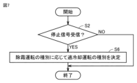
- FIG. 7 is a flowchart showing the processing of the control device 100 in this embodiment.
- the control device 100 identifies the type of defrosting operation contained in the stop signal. Then, the control device 100 refers to the table in FIG. 6 to determine the supercooling operation to be performed.
- the control device 100 decides to perform the first supercooling operation.
- the refrigeration cycle device 1B first performs the first supercooling operation, and after the first supercooling operation is completed, performs the first defrosting operation.
- the control device 100 decides to perform the second supercooling operation.
- the refrigeration cycle device 1B first performs the second supercooling operation, and after the second supercooling operation is completed, performs the second defrosting operation.
- the refrigeration cycle apparatus 1B of this embodiment can perform a defrosting operation. Furthermore, the refrigeration cycle apparatus 1B can lower the temperature of the first refrigerant in advance before a defrosting operation in which the temperature of the first refrigerant may rise. Therefore, even if the pump operation is stopped due to the defrosting operation, the increase in pressure of the first refrigerant can be suppressed. Furthermore, the refrigeration cycle apparatus 1B of this embodiment can perform a cooling operation according to the degree of increase in pressure of the first refrigerant, since the degree of increase in pressure varies depending on the type of defrosting operation.
- the defrosting operation and the supercooling operation may both be of one type.
- the refrigeration cycle device 1B executes the defrosting operation after the supercooling operation.
- the refrigeration cycle apparatus 1B may also be operated at the above-mentioned minimum refrigeration capacity during the defrosting operation. This allows the refrigeration cycle apparatus 1B to suppress an excessive increase in the pressure of the first refrigerant during the defrosting operation.
- the refrigeration cycle device includes a tank (for example, liquid tank 31) for temporarily storing the first refrigerant that becomes surplus during operation of the refrigeration cycle device.
- a tank for example, liquid tank 31
- the liquid tank 31 can be made smaller or the liquid tank 31 can be omitted is described.
- FIG. 8 shows an example of the configuration of a refrigeration cycle apparatus 1C according to the fourth embodiment.
- the first heat exchanger 61 of the refrigeration cycle apparatus 1B (see FIG. 4) is replaced with a shell-and-tube heat exchanger 61A, and the second refrigerant circuit C2 of the outdoor unit 20 is equipped with a second valve 25.
- the shell-and-tube heat exchanger 61A is, for example, a "flooded shell-and-tube heat exchanger.”
- the shell-and-tube heat exchanger 61A has the function of the first heat exchanger 61 and the function of temporarily storing the first refrigerant (i.e., the function of the liquid tank 31). Specifically, the shell-and-tube heat exchanger 61A temporarily stores the first refrigerant cooled by the second refrigerant. In this way, the refrigeration cycle device 1C is provided with the shell-and-tube heat exchanger 61A as the first heat exchanger, and therefore, even if the amount of the first refrigerant charged is large, the first refrigerant can be temporarily stored, and therefore the pressure of the first refrigerant can be prevented from increasing excessively.
- the liquid tank 31 can be made smaller or the liquid tank 31 can be omitted.
- the first heat exchanger may be another heat exchanger as long as it has the function of the first heat exchanger 61 and the function of temporarily storing the first refrigerant.
- the total amount F of the amount of the first refrigerant stored in the liquid tank 31 and the amount of the first refrigerant stored in the shell-and-tube heat exchanger 61A will be explained.
- the total amount F is determined based on the enclosed mass M of the first refrigerant and a predetermined density D. Specifically, it is determined by the following formula (1).
- FIG. 9 is a diagram for explaining how to determine the density D.
- the designer determines the design pressure of all components (pipes, etc.) of the indoor unit 10.
- the design pressure is set to 4.15 MPa, taking into consideration the use of piping in which a fluorocarbon refrigerant is used.
- the normal pressure during normal operation when the liquid pump 32 is in operation is assumed to be 1 MPa.
- the designer determines the maximum temperature that the first refrigerant can reach depending on the ambient environment of the refrigeration cycle device 1C.
- the maximum temperature is assumed to be 43 degrees.
- the design density at which the isotherm of the maximum temperature (43 degrees) intersects with the design pressure (4.15 MPa) is used as the density D.
- the design density is assumed to be 87 kg/m 3 .
- the refrigeration cycle apparatus 1C also includes a second valve 25.
- the second valve 25 is a valve for discharging the first refrigerant to a space other than the space to be cooled by the refrigeration cycle apparatus 1 (i.e., the outside).
- An unexpected event may be, for example, a power outage.
- the control device 100 or an operator opens the second valve 25.
- the first refrigerant is discharged to the outside, so that damage to parts of the refrigeration cycle apparatus 1C can be suppressed even if the pressure of the first refrigerant rises excessively.
- the second valve 25 may be provided in any of the refrigeration cycle apparatuses 1, 1A, and 1B.
- control device 100 may be configured to control the outdoor unit 20 but not the indoor unit 10.
- the control device 100 receives a signal from the indoor unit 10 indicating the operating state of the indoor unit 10 and controls the outdoor unit 20.
- the liquid pump 32 may be controlled to start and stop, etc., so that the liquid pump 32 itself performs the same processing as described in the above embodiment.
- the flow rate adjustment valve 34 may be controlled so that the flow rate adjustment valve 34 itself performs the same processing as described in the above embodiment.
- a control device other than the control device 100 may control at least one of the liquid pump 32 and the flow rate adjustment valve 34.
- 1 refrigeration cycle device 4 first pipe, 5 second pipe, 10 indoor unit, 20 outdoor unit, 21 compressor, 23 expansion valve, 25 second valve, 27, 28 valve, 31 liquid tank, 32 liquid pump, 34 flow control valve, 41, 42, 43, 44, 45, 46, 47, 48 temperature sensor, 51, 52, 53, 54 pressure sensor, 61 first heat exchanger, 61A shell-and-tube heat exchanger, 62 second heat exchanger, 63 third heat exchanger, 64 fourth heat exchanger, 100 control device, 102 CPU, 104 memory.
Landscapes
- Engineering & Computer Science (AREA)
- Physics & Mathematics (AREA)
- Mechanical Engineering (AREA)
- Thermal Sciences (AREA)
- General Engineering & Computer Science (AREA)
- Chemical & Material Sciences (AREA)
- Chemical Kinetics & Catalysis (AREA)
- Air Conditioning Control Device (AREA)
Priority Applications (3)
| Application Number | Priority Date | Filing Date | Title |
|---|---|---|---|
| DE112023006351.6T DE112023006351T5 (de) | 2023-05-16 | 2023-05-16 | Kältekreislaufvorrichtung |
| JP2025520312A JPWO2024236742A1 (https=) | 2023-05-16 | 2023-05-16 | |
| PCT/JP2023/018316 WO2024236742A1 (ja) | 2023-05-16 | 2023-05-16 | 冷凍サイクル装置 |
Applications Claiming Priority (1)
| Application Number | Priority Date | Filing Date | Title |
|---|---|---|---|
| PCT/JP2023/018316 WO2024236742A1 (ja) | 2023-05-16 | 2023-05-16 | 冷凍サイクル装置 |
Publications (1)
| Publication Number | Publication Date |
|---|---|
| WO2024236742A1 true WO2024236742A1 (ja) | 2024-11-21 |
Family
ID=93518916
Family Applications (1)
| Application Number | Title | Priority Date | Filing Date |
|---|---|---|---|
| PCT/JP2023/018316 Ceased WO2024236742A1 (ja) | 2023-05-16 | 2023-05-16 | 冷凍サイクル装置 |
Country Status (3)
| Country | Link |
|---|---|
| JP (1) | JPWO2024236742A1 (https=) |
| DE (1) | DE112023006351T5 (https=) |
| WO (1) | WO2024236742A1 (https=) |
Citations (10)
| Publication number | Priority date | Publication date | Assignee | Title |
|---|---|---|---|---|
| JP2004190917A (ja) * | 2002-12-10 | 2004-07-08 | Sanyo Electric Co Ltd | 冷凍装置 |
| JP2007147267A (ja) * | 2005-10-28 | 2007-06-14 | Toyo Eng Works Ltd | 自然冷媒冷却システム |
| JP2008175522A (ja) * | 2006-12-20 | 2008-07-31 | Mayekawa Mfg Co Ltd | 空調設備のリニューアルユニット及びそれを用いた空調設備の施工方法 |
| JP2008309393A (ja) * | 2007-06-14 | 2008-12-25 | Toyo Eng Works Ltd | 冷却システム |
| JP2012052767A (ja) * | 2010-09-03 | 2012-03-15 | Mitsubishi Electric Corp | ヒートポンプ装置 |
| JP2012215370A (ja) * | 2011-04-01 | 2012-11-08 | Toyo Eng Works Ltd | 二酸化炭素循環・冷却システムにおけるデフロスト装置 |
| JP2013160427A (ja) * | 2012-02-03 | 2013-08-19 | Mitsubishi Electric Corp | 二元冷凍装置 |
| JP2017227396A (ja) * | 2016-06-23 | 2017-12-28 | サンデンホールディングス株式会社 | 二元冷凍サイクル装置 |
| JP2019060581A (ja) * | 2017-09-28 | 2019-04-18 | パナソニックIpマネジメント株式会社 | 冷凍サイクル装置 |
| WO2022003754A1 (ja) * | 2020-06-29 | 2022-01-06 | 三菱電機株式会社 | 冷凍サイクル装置 |
-
2023
- 2023-05-16 JP JP2025520312A patent/JPWO2024236742A1/ja active Pending
- 2023-05-16 WO PCT/JP2023/018316 patent/WO2024236742A1/ja not_active Ceased
- 2023-05-16 DE DE112023006351.6T patent/DE112023006351T5/de active Pending
Patent Citations (10)
| Publication number | Priority date | Publication date | Assignee | Title |
|---|---|---|---|---|
| JP2004190917A (ja) * | 2002-12-10 | 2004-07-08 | Sanyo Electric Co Ltd | 冷凍装置 |
| JP2007147267A (ja) * | 2005-10-28 | 2007-06-14 | Toyo Eng Works Ltd | 自然冷媒冷却システム |
| JP2008175522A (ja) * | 2006-12-20 | 2008-07-31 | Mayekawa Mfg Co Ltd | 空調設備のリニューアルユニット及びそれを用いた空調設備の施工方法 |
| JP2008309393A (ja) * | 2007-06-14 | 2008-12-25 | Toyo Eng Works Ltd | 冷却システム |
| JP2012052767A (ja) * | 2010-09-03 | 2012-03-15 | Mitsubishi Electric Corp | ヒートポンプ装置 |
| JP2012215370A (ja) * | 2011-04-01 | 2012-11-08 | Toyo Eng Works Ltd | 二酸化炭素循環・冷却システムにおけるデフロスト装置 |
| JP2013160427A (ja) * | 2012-02-03 | 2013-08-19 | Mitsubishi Electric Corp | 二元冷凍装置 |
| JP2017227396A (ja) * | 2016-06-23 | 2017-12-28 | サンデンホールディングス株式会社 | 二元冷凍サイクル装置 |
| JP2019060581A (ja) * | 2017-09-28 | 2019-04-18 | パナソニックIpマネジメント株式会社 | 冷凍サイクル装置 |
| WO2022003754A1 (ja) * | 2020-06-29 | 2022-01-06 | 三菱電機株式会社 | 冷凍サイクル装置 |
Also Published As
| Publication number | Publication date |
|---|---|
| DE112023006351T5 (de) | 2026-02-26 |
| JPWO2024236742A1 (https=) | 2024-11-21 |
Similar Documents
| Publication | Publication Date | Title |
|---|---|---|
| JP3988780B2 (ja) | 冷凍装置 | |
| CN101842645A (zh) | 冷冻循环装置 | |
| CN116255749B (zh) | 温控机组、温度控制方法、温度控制装置及控制器 | |
| JP2011521194A (ja) | 冷媒蒸気圧縮システムにおける充填管理 | |
| JP3983520B2 (ja) | 超臨界蒸気圧縮システムおよび超臨界蒸気圧縮システムを循環する冷媒の高圧成分の圧力を調整する吸入ライン熱交換器 | |
| JP6778884B2 (ja) | 冷凍サイクル装置 | |
| JP6420686B2 (ja) | 冷凍サイクル装置 | |
| JPWO2017221287A1 (ja) | 冷却装置 | |
| JP2007514919A (ja) | 過圧防止アキュムレータを用いる蒸気圧縮システム | |
| JP2019163892A (ja) | 地中熱ヒートポンプ装置 | |
| JP2008002759A (ja) | 二元冷凍システムおよび保冷庫 | |
| JP2007218459A (ja) | 冷凍サイクル装置および保冷庫 | |
| CN112577172B (zh) | 空调系统的制冷控制方法和装置、存储介质、空调系统 | |
| JP6004734B2 (ja) | 輸送用冷凍装置 | |
| JP4292525B2 (ja) | 蒸気圧縮式冷凍サイクルの冷媒量検知方法 | |
| WO2024236742A1 (ja) | 冷凍サイクル装置 | |
| JP2003336918A (ja) | 冷却装置 | |
| EP3290827A1 (en) | Defrosting without reversing refrigerant cycle | |
| JP2018044686A (ja) | 冷凍システム | |
| JP4096984B2 (ja) | 冷凍装置 | |
| JP2018112367A (ja) | 二元ヒートポンプ装置 | |
| JP2007051841A (ja) | 冷凍サイクル装置 | |
| JP7424870B2 (ja) | 空調装置 | |
| JP2008051370A (ja) | 水冷式冷凍システムおよびそのシステムを搭載する保冷庫 | |
| JP6881424B2 (ja) | 冷凍装置 |
Legal Events
| Date | Code | Title | Description |
|---|---|---|---|
| 121 | Ep: the epo has been informed by wipo that ep was designated in this application |
Ref document number: 23937484 Country of ref document: EP Kind code of ref document: A1 |
|
| ENP | Entry into the national phase |
Ref document number: 2025520312 Country of ref document: JP Kind code of ref document: A |
|
| WWE | Wipo information: entry into national phase |
Ref document number: 2025520312 Country of ref document: JP |
|
| WWE | Wipo information: entry into national phase |
Ref document number: 112023006351 Country of ref document: DE |
|
| WWP | Wipo information: published in national office |
Ref document number: 112023006351 Country of ref document: DE |