WO2024236627A1 - 医療デバイス - Google Patents
医療デバイス Download PDFInfo
- Publication number
- WO2024236627A1 WO2024236627A1 PCT/JP2023/017873 JP2023017873W WO2024236627A1 WO 2024236627 A1 WO2024236627 A1 WO 2024236627A1 JP 2023017873 W JP2023017873 W JP 2023017873W WO 2024236627 A1 WO2024236627 A1 WO 2024236627A1
- Authority
- WO
- WIPO (PCT)
- Prior art keywords
- tip
- distal
- resin layer
- layer
- medical device
- Prior art date
- Legal status (The legal status is an assumption and is not a legal conclusion. Google has not performed a legal analysis and makes no representation as to the accuracy of the status listed.)
- Ceased
Links
Images




Classifications
-
- A—HUMAN NECESSITIES
- A61—MEDICAL OR VETERINARY SCIENCE; HYGIENE
- A61M—DEVICES FOR INTRODUCING MEDIA INTO, OR ONTO, THE BODY; DEVICES FOR TRANSDUCING BODY MEDIA OR FOR TAKING MEDIA FROM THE BODY; DEVICES FOR PRODUCING OR ENDING SLEEP OR STUPOR
- A61M25/00—Catheters; Hollow probes
- A61M25/0067—Catheters; Hollow probes characterised by the distal end, e.g. tips
- A61M25/008—Strength or flexibility characteristics of the catheter tip
-
- A—HUMAN NECESSITIES
- A61—MEDICAL OR VETERINARY SCIENCE; HYGIENE
- A61M—DEVICES FOR INTRODUCING MEDIA INTO, OR ONTO, THE BODY; DEVICES FOR TRANSDUCING BODY MEDIA OR FOR TAKING MEDIA FROM THE BODY; DEVICES FOR PRODUCING OR ENDING SLEEP OR STUPOR
- A61M25/00—Catheters; Hollow probes
-
- A—HUMAN NECESSITIES
- A61—MEDICAL OR VETERINARY SCIENCE; HYGIENE
- A61M—DEVICES FOR INTRODUCING MEDIA INTO, OR ONTO, THE BODY; DEVICES FOR TRANSDUCING BODY MEDIA OR FOR TAKING MEDIA FROM THE BODY; DEVICES FOR PRODUCING OR ENDING SLEEP OR STUPOR
- A61M25/00—Catheters; Hollow probes
- A61M25/0009—Making of catheters or other medical or surgical tubes
- A61M25/0012—Making of catheters or other medical or surgical tubes with embedded structures, e.g. coils, braids, meshes, strands or radiopaque coils
-
- A—HUMAN NECESSITIES
- A61—MEDICAL OR VETERINARY SCIENCE; HYGIENE
- A61M—DEVICES FOR INTRODUCING MEDIA INTO, OR ONTO, THE BODY; DEVICES FOR TRANSDUCING BODY MEDIA OR FOR TAKING MEDIA FROM THE BODY; DEVICES FOR PRODUCING OR ENDING SLEEP OR STUPOR
- A61M25/00—Catheters; Hollow probes
- A61M25/0043—Catheters; Hollow probes characterised by structural features
- A61M25/0045—Catheters; Hollow probes characterised by structural features multi-layered, e.g. coated
-
- A—HUMAN NECESSITIES
- A61—MEDICAL OR VETERINARY SCIENCE; HYGIENE
- A61M—DEVICES FOR INTRODUCING MEDIA INTO, OR ONTO, THE BODY; DEVICES FOR TRANSDUCING BODY MEDIA OR FOR TAKING MEDIA FROM THE BODY; DEVICES FOR PRODUCING OR ENDING SLEEP OR STUPOR
- A61M25/00—Catheters; Hollow probes
- A61M25/0043—Catheters; Hollow probes characterised by structural features
- A61M25/005—Catheters; Hollow probes characterised by structural features with embedded materials for reinforcement, e.g. wires, coils, braids
-
- A—HUMAN NECESSITIES
- A61—MEDICAL OR VETERINARY SCIENCE; HYGIENE
- A61M—DEVICES FOR INTRODUCING MEDIA INTO, OR ONTO, THE BODY; DEVICES FOR TRANSDUCING BODY MEDIA OR FOR TAKING MEDIA FROM THE BODY; DEVICES FOR PRODUCING OR ENDING SLEEP OR STUPOR
- A61M25/00—Catheters; Hollow probes
- A61M25/0067—Catheters; Hollow probes characterised by the distal end, e.g. tips
- A61M25/0068—Static characteristics of the catheter tip, e.g. shape, atraumatic tip, curved tip or tip structure
-
- A—HUMAN NECESSITIES
- A61—MEDICAL OR VETERINARY SCIENCE; HYGIENE
- A61M—DEVICES FOR INTRODUCING MEDIA INTO, OR ONTO, THE BODY; DEVICES FOR TRANSDUCING BODY MEDIA OR FOR TAKING MEDIA FROM THE BODY; DEVICES FOR PRODUCING OR ENDING SLEEP OR STUPOR
- A61M25/00—Catheters; Hollow probes
- A61M25/0067—Catheters; Hollow probes characterised by the distal end, e.g. tips
- A61M25/0068—Static characteristics of the catheter tip, e.g. shape, atraumatic tip, curved tip or tip structure
- A61M25/0069—Tip not integral with tube
-
- A—HUMAN NECESSITIES
- A61—MEDICAL OR VETERINARY SCIENCE; HYGIENE
- A61M—DEVICES FOR INTRODUCING MEDIA INTO, OR ONTO, THE BODY; DEVICES FOR TRANSDUCING BODY MEDIA OR FOR TAKING MEDIA FROM THE BODY; DEVICES FOR PRODUCING OR ENDING SLEEP OR STUPOR
- A61M25/00—Catheters; Hollow probes
- A61M25/01—Introducing, guiding, advancing, emplacing or holding catheters
- A61M25/0105—Steering means as part of the catheter or advancing means; Markers for positioning
- A61M25/0108—Steering means as part of the catheter or advancing means; Markers for positioning using radio-opaque or ultrasound markers
-
- A—HUMAN NECESSITIES
- A61—MEDICAL OR VETERINARY SCIENCE; HYGIENE
- A61M—DEVICES FOR INTRODUCING MEDIA INTO, OR ONTO, THE BODY; DEVICES FOR TRANSDUCING BODY MEDIA OR FOR TAKING MEDIA FROM THE BODY; DEVICES FOR PRODUCING OR ENDING SLEEP OR STUPOR
- A61M25/00—Catheters; Hollow probes
- A61M25/0067—Catheters; Hollow probes characterised by the distal end, e.g. tips
- A61M25/008—Strength or flexibility characteristics of the catheter tip
- A61M2025/0081—Soft tip
Definitions
- the technology disclosed in this specification relates to medical devices.
- a catheter when a narrowing or obstruction (hereinafter collectively referred to as "narrowing") occurs in a body lumen (digestive organs such as the bile duct, gallbladder, pancreas, esophagus, duodenum, small intestine, large intestine, etc., blood vessels, ureters, trachea, etc.), a catheter is widely used as a treatment.
- a catheter has a configuration in which a tip tip made of a resin material is joined to the tip of a shaft having a reinforcing layer made of, for example, a coil body.
- This specification discloses a technology that can solve the problems mentioned above.
- the medical device disclosed in this specification comprises a distal tip, a reinforcing layer, and a resin layer.
- the distal tip contains a resin material and a radiopaque material.
- the reinforcing layer is connected to the base end of the distal tip.
- the resin layer is disposed radially outward of the distal tip, has a distal end located distal to the base end of the distal tip, and has a predetermined material property different from that of the distal tip.
- the tip tip contains a resin material and a radiopaque material, so the presence of the resin material ensures the flexibility (ease of stretching) of the tip tip, while the presence of the radiopaque material ensures the visibility of the tip tip under radiation without the need for a separate marker, or even with a thin marker.
- the tip of the resin layer which has different material properties from the tip tip, is located more distal than the base end of the tip tip, so the presence of the resin layer can reinforce the position of the base end of the tip tip and prevent breakage of the tip tip. Furthermore, the presence of the resin layer can reduce the rigidity gap at the connection position between the tip tip and the reinforcing layer in the medical device.
- the reinforcing layer may be a first reinforcing layer, and may further include a second reinforcing layer whose tip is located distal to the base end of the distal tip, and the tip of the resin layer may be located distal to the tip of the second reinforcing layer.
- the above medical device may further include an inner layer disposed radially inward of the second reinforcing layer, the inner layer having a tip located distal to the tip of the second reinforcing layer.
- the distal tip may have a taper that narrows toward the distal end and a straight portion disposed at the base end of the taper, and the distal end of the second reinforcing layer may be located on the base end side of the boundary between the taper and the straight portion.
- the predetermined material property may be a content ratio of radiopaque material, and the content ratio of radiopaque material in the resin layer may be lower than the content ratio of radiopaque material in the distal tip.
- the tip of the resin layer which has a lower content ratio of radiopaque material (i.e., a higher content ratio of resin material) compared to the distal tip and therefore has high flexibility (ease of stretching), is located on the distal side of the base end of the distal tip. Therefore, the presence of the highly elongate resin layer can suppress breakage of the distal tip. Furthermore, the presence of the highly flexible resin layer can reduce the rigidity gap at the connection position between the distal tip and the reinforcing layer in the medical device.
- the resin layer may be configured not to contain a radiopaque material. With this configuration, the flexibility (ease of stretching) of the resin layer can be effectively increased, and breakage of the distal tip can be effectively suppressed.
- the resin layer and the tip tip may be configured to contain the same type of resin material. With this configuration, the interfacial adhesive strength between the resin layer and the tip tip can be strengthened, and breakage of the tip tip can be effectively suppressed.
- the technology disclosed in this specification can be realized in various forms, such as a medical device including a catheter, a medical system having a medical device, a method for manufacturing a medical device or a medical system, etc.
- FIG. 1 is an explanatory diagram showing a configuration of a side surface of a catheter in a first embodiment.
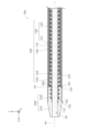
- FIG. 1 is an explanatory diagram showing the configuration of a longitudinal section (YZ section) of a tip portion of a catheter in a first embodiment.
- FIG. 13 is an explanatory diagram showing the configuration of a longitudinal section of the tip of a catheter in a second embodiment.
- FIG. 13 is an explanatory diagram showing the configuration of a longitudinal section of the tip of a catheter in a third embodiment.
- FIG. 13 is an explanatory diagram showing the configuration of a longitudinal section of the tip of a catheter according to a fourth embodiment.
- FIG. 1 is an explanatory diagram showing the configuration of a side surface of the catheter 10 in the first embodiment
- FIG. 2 is an explanatory diagram showing the configuration of a longitudinal section (YZ section) of the tip of the catheter 10 in the first embodiment.
- a part of the catheter 10 is omitted.
- the positive Z-axis direction side is the tip side (distal side) inserted into the body
- the negative Z-axis direction side is the base end side (proximal side) operated by an operator such as a doctor.
- a state in which the central axis Ax of a shaft 100 of the catheter 10 described later is parallel to the Z-axis is shown, but the shaft 100 is configured to be bendable.
- the tip end of the catheter 10 and each of its components is referred to as the "tip end”, the tip end and its vicinity are referred to as the “tip portion”, the base end end is referred to as the “base end”, and the base end and its vicinity are referred to as the "base end portion”.
- the catheter 10 is a medical device.
- the catheter 10 is inserted into a blood vessel.
- the total length of the catheter 10 is, for example, about 1000 mm to 2000 mm.
- the catheter 10 comprises a shaft 100, a distal tip 200, and a connector 300. At least a portion of the catheter 10 may be coated with a hydrophilic coating.
- the connector 300 is a member that is connected to the base end of the shaft 100 and constitutes the most proximal end of the catheter 10.
- the connector 300 may be provided with a port for connection to a syringe or the like.
- the connector 300 is formed, for example, from resin.
- the shaft 100 is a long, hollow member.
- the external shape of the cross section (XY cross section) at each position of the shaft 100 can be any shape, for example, approximately circular or approximately elliptical.
- the external diameter of the shaft 100 is, for example, approximately 0.2 mm to 1.5 mm.
- the external diameter of the shaft 100 may be approximately constant from the base end to the tip, or may vary along the longitudinal direction, for example, gradually decreasing in diameter from the base end to the tip.
- the shaft 100 has a first resin layer (inner layer) 110, a second resin layer (middle layer) 120, a third resin layer (outer layer) 130, a first reinforcing layer 140, and a second reinforcing layer 150.
- the first resin layer 110 is a cylindrical body that defines the inner circumferential surface of the lumen 12 into which, for example, a guide wire is inserted.
- the second resin layer 120 is a cylindrical body arranged radially outside the first resin layer 110.
- the third resin layer 130 is a cylindrical body arranged radially outside the second resin layer 120.
- the third resin layer 130 has a distal third resin layer 131 that constitutes the distal portion of the third resin layer 130, and a proximal third resin layer 135 that is located on the proximal side of the distal third resin layer 131.
- the boundary between the distal third resin layer 131 and the proximal third resin layer 135 is located on the proximal side of the proximal end 202 of the distal tip 200.
- the distal third resin layer 131 is an example of a resin layer.
- the first resin layer 110 is formed of, for example, polytetrafluoroethylene (PTFE).
- the second resin layer 120 is formed of, for example, polyamide.
- the distal third resin layer 131 is formed of a relatively soft resin material such as urethane, and the proximal third resin layer 135 is formed of, for example, polyamide.
- the distal third resin layer 131 does not contain a radiopaque material.
- not containing a radiopaque material means that the radiopaque material is substantially not contained, and includes aspects in which the radiopaque material is contained as an impurity.
- the first reinforcement layer 140 is a member for increasing the rigidity of the shaft 100, and is disposed between the second resin layer 120 and the third resin layer 130.
- the first reinforcement layer 140 is composed of a coil body in which wire is wound in a spiral shape.
- a welded portion 141 is formed at the tip of the first reinforcement layer 140 to gather the wire of the coil body.
- the welded portion 141 forms the tip 142 of the first reinforcement layer 140.
- the first reinforcement layer 140 is formed from a metal material such as stainless steel such as SUS304, tungsten, Ni-Ti alloy, or a resin material such as PEEK.
- the second reinforcing layer 150 is a member for increasing the rigidity of the shaft 100, and is disposed along the outer peripheral surface of the first resin layer 110. In this embodiment, the second reinforcing layer 150, except for its tip, is embedded in the second resin layer 120. In this embodiment, the second reinforcing layer 150 is composed of a tubular body (a so-called braid) in which multiple wires are woven into a mesh shape.
- the second reinforcing layer 150 is formed from a metal material such as stainless steel, e.g. SUS304, tungsten, or a Ni-Ti alloy, or a resin material such as PEEK.
- the distal tip 200 is a hollow member that constitutes the most distal end of the catheter 10.
- the hollow portion of the distal tip 200 is connected to the hollow portion of the shaft 100 and defines the inner circumferential surface of the lumen 12 of the catheter 10.
- the distal tip 200 is formed of a relatively soft resin material such as urethane.
- the distal tip 200 contains a radiopaque material (e.g., tungsten) at a predetermined content ratio.
- the distal third resin layer 131 does not contain a radiopaque material, so the distal third resin layer 131 and the distal tip 200 differ from each other in the characteristic of the content ratio of the radiopaque material.
- the content ratio of the radiopaque material is an example of a predetermined material characteristic. It is preferable that the distal third resin layer 131 and the distal tip 200 contain the same type of resin material. It is even more preferable that the distal third resin layer 131 and the distal tip 200 contain the same type and grade of resin material.
- the distal tip 200 has a taper 210 and a straight section 220.
- the taper 210 constitutes the distal end of the distal tip 200.
- the taper 210 has a tapered shape in which the outer diameter gradually narrows toward the tip.
- the straight section 220 is disposed at the base end of the taper 210 and constitutes the proximal end of the distal tip 200.
- the straight section 220 has a straight shape in which the outer diameter is equal to or greater than the outer diameter of the proximal end of the taper 210.
- the tip 142 of the first reinforcement layer 140 is connected to the base end 202 of the tip tip 200. That is, the tip tip 200 and the shaft 100 are connected to each other at the boundary position (hereinafter referred to as "connection position P1") between the tip 142 of the first reinforcement layer 140 and the base end 202 of the tip tip 200.
- connection position P1 the boundary position between the tip 142 of the first reinforcement layer 140 and the base end 202 of the tip tip 200.
- the first resin layer 110 and the second reinforcement layer 150 constituting the shaft 100 extend beyond the base end 202 (connection position P1) of the tip tip 200 and further to the tip side.
- the tip 112 of the first resin layer 110 is located at the same position as the tip 152 of the second reinforcement layer 150, or is located further to the tip side than the tip 152.
- the tip 122 of the second resin layer 120 is located on the base end side than the base end 202 (connection position P1) of the tip tip 200.
- the distal third resin layer 131 of the third resin layer 130 constituting the shaft 100 extends beyond the base end 202 (connection position P1) of the distal tip 200 and further to the distal side. That is, the distal third resin layer 131 extends in the direction of the central axis Ax so as to straddle the connection position P1 between the distal tip 200 and the shaft 100. That is, the distal third resin layer 131 extends in the direction of the central axis Ax so as to straddle the connection position P1 between the distal tip 200 and the main part of the shaft 100.
- the tip 132 of the distal third resin layer 131 is located on the proximal side of the tip 152 of the second reinforcing layer 150.
- the distance from the connection position P1 along the central axis Ax to the tip 132 of the distal third resin layer 131 is preferably 1/3 or more of the length of the straight part 220 of the distal tip 200, and more preferably 2/3 or more of the length.
- the catheter 10 of this embodiment includes the distal tip 200, the first reinforcing layer 140, and the distal third resin layer 131.
- the distal tip 200 contains a resin material and a radiopaque material.
- the first reinforcing layer 140 is connected to the base end of the distal tip 200.
- the distal third resin layer 131 is disposed radially outward of the distal tip 200.
- the distal tip 132 of the distal third resin layer 131 is located distally of the base end 202 of the distal tip 200.
- the distal third resin layer 131 differs from the distal tip 200 in the content ratio of the radiopaque material. More specifically, the content ratio of the radiopaque material in the distal third resin layer 131 is lower than the content ratio of the radiopaque material in the distal tip 200.
- the distal tip 200 contains a resin material and a radiopaque material, so that the presence of the resin material ensures the flexibility (ease of stretching) of the distal tip 200, while the presence of the radiopaque material ensures the visibility of the distal tip 200 under radiation without providing a separate marker or even with a thin marker.
- the distal tip 132 of the distal third resin layer 131 which has a lower content of radiopaque material (i.e., a higher content of resin material) compared to the distal tip 200 and therefore has a higher flexibility (ease of stretching), is located on the distal side of the base end 202 of the distal tip 200.
- the presence of the distal third resin layer 131 which has a high elongation, can reinforce the position of the base end 202 of the distal tip 200, and breakage of the distal tip 200 can be suppressed. Furthermore, the presence of the distal third resin layer 131, which has a high flexibility, can reduce the rigidity gap at the connection position P1 between the distal tip 200 and the first reinforcing layer 140 in the catheter 10.
- the distal end third resin layer 131 does not contain a radiopaque material. Therefore, the flexibility (ease of stretching) of the distal end third resin layer 131 can be effectively increased, and breakage of the distal tip 200 can be effectively suppressed.
- the distal end third resin layer 131 and the distal tip 200 contain the same type of resin material. With this configuration, the interfacial adhesive strength between the distal end third resin layer 131 and the distal tip 200 can be strengthened, and breakage of the distal tip 200 can be effectively suppressed.
- Table 1 shows the breaking strength (average, minimum, maximum, standard deviation) determined by tensile testing.
- the comparative example is a configuration in which the tip 132 of the distal third resin layer 131 is located at the base end 202 of the distal tip 200. That is, in the comparative example, the connection position P1 between the distal tip 200 and the shaft 100 is not covered by the distal third resin layer 131.
- the average breaking strength of the catheters of the example was approximately 2 N greater than the average breaking strength of the catheters of the comparative example. This result confirmed that the catheter 10 having the configuration of this embodiment can suppress breakage of the distal tip 200.
- Second embodiment: 3 is an explanatory diagram showing the configuration of a longitudinal section of the tip portion of the catheter 10a in the second embodiment.
- the same configurations as those of the catheter 10 in the first embodiment described above are denoted by the same reference numerals and the description thereof will be omitted as appropriate.
- the catheter 10a of the second embodiment differs from the catheter 10 of the first embodiment in the configuration of the distal end third resin layer 131.
- the distal end 132 of the distal end third resin layer 131 is located distally of the base end 202 of the distal tip 200.
- the distal end third resin layer 131 extends further distally, and the distal end 132 of the distal end third resin layer 131 is located distally of the distal end 152 of the second reinforcing layer 150.
- the distal end third resin layer 131 extends in the direction of the central axis Ax so as to straddle the connection position P1 between the distal tip 200 and the shaft 100 and the position of the distal end 152 of the second reinforcing layer 150.
- the tip 152 of the second reinforcing layer 150 is located further distal than the base end 202 of the distal tip 200.
- the tip 132 of the distal third resin layer 131 is located further distal than the tip 152 of the second reinforcing layer 150. Therefore, according to the catheter 10a of the second embodiment, the distal third resin layer 131, which has high stretchability, can be disposed at the position of the tip 152 of the second reinforcing layer 150, where breakage is likely to occur due to the relatively large rigidity gap in the distal tip 200, and breakage of the distal tip 200 can be more effectively suppressed.
- the catheter 10a of the second embodiment further includes a first resin layer 110 disposed radially inward of the second reinforcing layer 150.
- the tip 112 of the first resin layer 110 is located closer to the tip side than the tip 152 of the second reinforcing layer 150. Therefore, according to the catheter 10a of the second embodiment, the presence of the first resin layer 110 can effectively reduce the rigidity gap at the tip 152 of the second reinforcing layer 150, and breakage of the tip tip 200 can be further effectively suppressed.
- the tip 152 of the second reinforcement layer 150 is located on the base end side of the boundary between the taper 210 and the straight portion 220 of the distal tip 200.
- the rigidity gap at the boundary position becomes large.
- a rigidity gap occurs in the taper 210, which is the thin part of the distal tip 200, due to the presence or absence of the second reinforcement layer 150, and the rigidity gap becomes large at the tip 152 of the second reinforcement layer 150.
- the tip 152 of the second reinforcement layer 150 is located on the base end side of the above boundary, so that an appropriate gradual change in rigidity can be achieved.
- Third embodiment 4 is an explanatory diagram showing the configuration of a longitudinal section of the tip portion of a catheter 10b in the third embodiment.
- the same configurations as those of the catheter 10 in the first embodiment described above are denoted by the same reference numerals and the description thereof will be omitted as appropriate.
- the catheter 10b of the third embodiment differs from the catheter 10 of the first embodiment in the configuration of the third resin layer 130.
- the third resin layer 130 is not divided into a distal third resin layer 131 and a proximal third resin layer 135, but is formed from a single resin material (e.g., polyamide).
- the distal end of the third resin layer 130 is located at approximately the same position as the proximal end 202 of the distal tip 200.
- the shaft 100 further includes a fourth resin layer 160.
- the fourth resin layer 160 is formed of, for example, a relatively soft urethane resin.
- the fourth resin layer 160 does not contain a radiopaque material.
- the fourth resin layer 160 is disposed along the outer peripheral surface of the third resin layer 130 and the outer peripheral surface of the distal tip 200.
- the distal end 162 of the fourth resin layer 160 is located on the distal side of the proximal end 202 of the distal tip 200, and the proximal end 164 of the fourth resin layer 160 is located on the proximal side of the proximal end 202 of the distal tip 200. That is, the fourth resin layer 160 extends in the direction of the central axis Ax so as to straddle the connection position P1 between the distal tip 200 and the shaft 100.
- the fourth resin layer 160 is an example of a resin layer.
- the catheter 10b of the third embodiment has a fourth resin layer 160 arranged radially outside the distal tip 200.
- the distal end 162 of the fourth resin layer 160 is located distally of the base end 202 of the distal tip 200.
- the fourth resin layer 160 has a different content of radiopaque material from that of the distal tip 200. More specifically, the content of radiopaque material in the fourth resin layer 160 is lower than that of the distal tip 200. That is, the distal end 162 of the fourth resin layer 160, which has a lower content of radiopaque material compared to the distal tip 200 and therefore is more flexible (stretchable), is located distally of the base end 202 of the distal tip 200.
- Fourth embodiment: 5 is an explanatory diagram showing the configuration of a longitudinal section of the tip portion of the catheter 10c in the fourth embodiment.
- the same configurations as those of the catheter 10b in the third embodiment described above are denoted by the same reference numerals and the description thereof will be omitted as appropriate.
- the catheter 10c of the fourth embodiment differs from the catheter 10b of the third embodiment in the configuration of the fourth resin layer 160.
- the tip 162 of the fourth resin layer 160 is located further distal than the base end 202 of the tip tip 200.
- the fourth resin layer 160 extends further distally, and the tip 162 of the fourth resin layer 160 is located further distal than the tip 152 of the second reinforcing layer 150. That is, the fourth resin layer 160 extends in the direction of the central axis Ax so as to straddle the connection position P1 between the tip tip 200 and the shaft 100 and the position of the tip 152 of the second reinforcing layer 150.
- the tip 162 of the fourth resin layer 160 is located further towards the tip side than the tip 152 of the second reinforcing layer 150. Therefore, according to the catheter 10c of the fourth embodiment, the fourth resin layer 160, which has high stretchability, can be placed at the position of the tip 152 of the second reinforcing layer 150, where breakage is likely to occur due to the relatively large rigidity gap in the tip tip 200, and breakage of the tip tip 200 can be more effectively suppressed.
- the shaft 100 has two reinforcing layers, the first reinforcing layer 140 and the second reinforcing layer 150, but the number of reinforcing layers in the shaft 100 may be one, or three or more.
- the configuration of the reinforcing layers in the shaft 100 may be changed as desired.
- the shaft 100 may have one or more coil bodies and/or braids as reinforcing layers, or may have reinforcing layers other than coil bodies and braids.
- the distal third resin layer 131 or the fourth resin layer 160 does not contain a radiopaque material, but the distal third resin layer 131 or the fourth resin layer 160 may contain a radiopaque material at a content lower than the content of the radiopaque material in the distal tip 200.
- first resin layer 110 the second resin layer 120, the third resin layer 130, the first reinforcing layer 140, the second reinforcing layer 150, the fourth resin layer 160, and the tip tip 200 in the above embodiment are merely examples, and each part may be formed from other materials.
- the distal third resin layer 131 or the fourth resin layer 160 and the distal tip 200 differ from each other in the characteristic of the content ratio of the radiopaque material, but instead of or in addition to this, other material properties of the two may differ from each other.
- the specified material property may be the ease of stretching (Young's modulus).
- the specified material property may be the breaking strength.
- the specified material property may be the type of resin material contained.
- the specified material property may be the grade (Shore hardness) of the resin material contained.
- the specified material property may be the type of radiopaque material contained.
- the catheter 10 may be inserted into a body lumen other than a blood vessel (digestive organs such as the bile duct, gallbladder, pancreas, esophagus, duodenum, small intestine, large intestine, ureter, trachea, etc.).
- a blood vessel digestive organs such as the bile duct, gallbladder, pancreas, esophagus, duodenum, small intestine, large intestine, ureter, trachea, etc.
Landscapes
- Health & Medical Sciences (AREA)
- Life Sciences & Earth Sciences (AREA)
- Biophysics (AREA)
- Pulmonology (AREA)
- Engineering & Computer Science (AREA)
- Anesthesiology (AREA)
- Biomedical Technology (AREA)
- Heart & Thoracic Surgery (AREA)
- Hematology (AREA)
- Animal Behavior & Ethology (AREA)
- General Health & Medical Sciences (AREA)
- Public Health (AREA)
- Veterinary Medicine (AREA)
- Media Introduction/Drainage Providing Device (AREA)
Priority Applications (5)
| Application Number | Priority Date | Filing Date | Title |
|---|---|---|---|
| JP2025520213A JPWO2024236627A1 (https=) | 2023-05-12 | 2023-05-12 | |
| EP23937374.9A EP4710980A1 (en) | 2023-05-12 | 2023-05-12 | Medical device |
| CN202380097916.0A CN121263227A (zh) | 2023-05-12 | 2023-05-12 | 医疗设备 |
| PCT/JP2023/017873 WO2024236627A1 (ja) | 2023-05-12 | 2023-05-12 | 医療デバイス |
| US19/386,368 US20260069830A1 (en) | 2023-05-12 | 2025-11-12 | Medical device |
Applications Claiming Priority (1)
| Application Number | Priority Date | Filing Date | Title |
|---|---|---|---|
| PCT/JP2023/017873 WO2024236627A1 (ja) | 2023-05-12 | 2023-05-12 | 医療デバイス |
Related Child Applications (1)
| Application Number | Title | Priority Date | Filing Date |
|---|---|---|---|
| US19/386,368 Continuation US20260069830A1 (en) | 2023-05-12 | 2025-11-12 | Medical device |
Publications (1)
| Publication Number | Publication Date |
|---|---|
| WO2024236627A1 true WO2024236627A1 (ja) | 2024-11-21 |
Family
ID=93518776
Family Applications (1)
| Application Number | Title | Priority Date | Filing Date |
|---|---|---|---|
| PCT/JP2023/017873 Ceased WO2024236627A1 (ja) | 2023-05-12 | 2023-05-12 | 医療デバイス |
Country Status (5)
| Country | Link |
|---|---|
| US (1) | US20260069830A1 (https=) |
| EP (1) | EP4710980A1 (https=) |
| JP (1) | JPWO2024236627A1 (https=) |
| CN (1) | CN121263227A (https=) |
| WO (1) | WO2024236627A1 (https=) |
Citations (7)
| Publication number | Priority date | Publication date | Assignee | Title |
|---|---|---|---|---|
| JP2005329062A (ja) * | 2004-05-20 | 2005-12-02 | Terumo Corp | イントロデューサーシース |
| JP2015181787A (ja) * | 2014-03-25 | 2015-10-22 | 朝日インテック株式会社 | カテーテル |
| JP2015208425A (ja) * | 2014-04-25 | 2015-11-24 | 朝日インテック株式会社 | カテーテル |
| WO2018042596A1 (ja) | 2016-09-01 | 2018-03-08 | 朝日インテック株式会社 | カテーテル |
| WO2019181837A1 (ja) * | 2018-03-19 | 2019-09-26 | 日本ゼオン株式会社 | 結石除去用バルーンカテーテル |
| WO2020161811A1 (ja) * | 2019-02-06 | 2020-08-13 | 朝日インテック株式会社 | カテーテル、および、カテーテルの製造方法 |
| WO2022009287A1 (ja) * | 2020-07-06 | 2022-01-13 | 朝日インテック株式会社 | カテーテル |
-
2023
- 2023-05-12 JP JP2025520213A patent/JPWO2024236627A1/ja active Pending
- 2023-05-12 CN CN202380097916.0A patent/CN121263227A/zh active Pending
- 2023-05-12 EP EP23937374.9A patent/EP4710980A1/en active Pending
- 2023-05-12 WO PCT/JP2023/017873 patent/WO2024236627A1/ja not_active Ceased
-
2025
- 2025-11-12 US US19/386,368 patent/US20260069830A1/en active Pending
Patent Citations (7)
| Publication number | Priority date | Publication date | Assignee | Title |
|---|---|---|---|---|
| JP2005329062A (ja) * | 2004-05-20 | 2005-12-02 | Terumo Corp | イントロデューサーシース |
| JP2015181787A (ja) * | 2014-03-25 | 2015-10-22 | 朝日インテック株式会社 | カテーテル |
| JP2015208425A (ja) * | 2014-04-25 | 2015-11-24 | 朝日インテック株式会社 | カテーテル |
| WO2018042596A1 (ja) | 2016-09-01 | 2018-03-08 | 朝日インテック株式会社 | カテーテル |
| WO2019181837A1 (ja) * | 2018-03-19 | 2019-09-26 | 日本ゼオン株式会社 | 結石除去用バルーンカテーテル |
| WO2020161811A1 (ja) * | 2019-02-06 | 2020-08-13 | 朝日インテック株式会社 | カテーテル、および、カテーテルの製造方法 |
| WO2022009287A1 (ja) * | 2020-07-06 | 2022-01-13 | 朝日インテック株式会社 | カテーテル |
Non-Patent Citations (1)
| Title |
|---|
| See also references of EP4710980A1 |
Also Published As
| Publication number | Publication date |
|---|---|
| US20260069830A1 (en) | 2026-03-12 |
| JPWO2024236627A1 (https=) | 2024-11-21 |
| CN121263227A (zh) | 2026-01-02 |
| EP4710980A1 (en) | 2026-03-18 |
Similar Documents
| Publication | Publication Date | Title |
|---|---|---|
| JP4743800B2 (ja) | カテーテル | |
| US9339629B2 (en) | Catheter | |
| US10166363B2 (en) | Catheter | |
| CN113365685B (zh) | 延长导管及其制造方法 | |
| US20240325045A1 (en) | Elongated medical body | |
| US12447307B2 (en) | Catheters and methods for producing catheters | |
| US20250249205A1 (en) | Catheter | |
| US20240091495A1 (en) | Catheter reinforcement layer and catheter | |
| US20200215300A1 (en) | Catheter, separator, and suction system | |
| JPWO2020162286A1 (ja) | 延長カテーテル、及びその製造方法 | |
| JP5110716B2 (ja) | カテーテル | |
| WO2024236627A1 (ja) | 医療デバイス | |
| JP7762635B2 (ja) | カテーテル | |
| CN215083905U (zh) | 一种导管加强层和导管 | |
| US20220105310A1 (en) | Hollow shaft and catheter | |
| US20220323720A1 (en) | Support catheter and tube | |
| JP6343574B2 (ja) | カテーテル | |
| WO2018074074A1 (ja) | カテーテル組立体 | |
| WO2024004824A1 (ja) | カテーテル | |
| WO2023095838A1 (ja) | カテーテル | |
| WO2026062994A1 (ja) | カテーテル | |
| WO2023095694A1 (ja) | カテーテル | |
| JP2024058700A (ja) | カテーテル | |
| WO2024127750A1 (ja) | カテーテル | |
| JP2025145117A (ja) | カテーテル |
Legal Events
| Date | Code | Title | Description |
|---|---|---|---|
| 121 | Ep: the epo has been informed by wipo that ep was designated in this application |
Ref document number: 23937374 Country of ref document: EP Kind code of ref document: A1 |
|
| ENP | Entry into the national phase |
Ref document number: 2025520213 Country of ref document: JP Kind code of ref document: A |
|
| WWE | Wipo information: entry into national phase |
Ref document number: 2025520213 Country of ref document: JP |
|
| WWE | Wipo information: entry into national phase |
Ref document number: 2023937374 Country of ref document: EP |
|
| NENP | Non-entry into the national phase |
Ref country code: DE |
|
| ENP | Entry into the national phase |
Ref document number: 2023937374 Country of ref document: EP Effective date: 20251212 |
|
| ENP | Entry into the national phase |
Ref document number: 2023937374 Country of ref document: EP Effective date: 20251212 |
|
| ENP | Entry into the national phase |
Ref document number: 2023937374 Country of ref document: EP Effective date: 20251212 |
|
| ENP | Entry into the national phase |
Ref document number: 2023937374 Country of ref document: EP Effective date: 20251212 |
|
| ENP | Entry into the national phase |
Ref document number: 2023937374 Country of ref document: EP Effective date: 20251212 |
|
| ENP | Entry into the national phase |
Ref document number: 2023937374 Country of ref document: EP Effective date: 20251212 |
|
| ENP | Entry into the national phase |
Ref document number: 2023937374 Country of ref document: EP Effective date: 20251212 |
|
| ENP | Entry into the national phase |
Ref document number: 2023937374 Country of ref document: EP Effective date: 20251212 |
|
| ENP | Entry into the national phase |
Ref document number: 2023937374 Country of ref document: EP Effective date: 20251212 |
|
| WWP | Wipo information: published in national office |
Ref document number: 2023937374 Country of ref document: EP |