WO2024232424A1 - 車両用灯具、及び導光体 - Google Patents
車両用灯具、及び導光体 Download PDFInfo
- Publication number
- WO2024232424A1 WO2024232424A1 PCT/JP2024/017332 JP2024017332W WO2024232424A1 WO 2024232424 A1 WO2024232424 A1 WO 2024232424A1 JP 2024017332 W JP2024017332 W JP 2024017332W WO 2024232424 A1 WO2024232424 A1 WO 2024232424A1
- Authority
- WO
- WIPO (PCT)
- Prior art keywords
- rod
- shaped light
- light
- light guiding
- shaped
- Prior art date
- Legal status (The legal status is an assumption and is not a legal conclusion. Google has not performed a legal analysis and makes no representation as to the accuracy of the status listed.)
- Ceased
Links
Images


Classifications
-
- F—MECHANICAL ENGINEERING; LIGHTING; HEATING; WEAPONS; BLASTING
- F21—LIGHTING
- F21S—NON-PORTABLE LIGHTING DEVICES; SYSTEMS THEREOF; VEHICLE LIGHTING DEVICES SPECIALLY ADAPTED FOR VEHICLE EXTERIORS
- F21S2/00—Systems of lighting devices, not provided for in main groups F21S4/00 - F21S10/00 or F21S19/00, e.g. of modular construction
-
- F—MECHANICAL ENGINEERING; LIGHTING; HEATING; WEAPONS; BLASTING
- F21—LIGHTING
- F21S—NON-PORTABLE LIGHTING DEVICES; SYSTEMS THEREOF; VEHICLE LIGHTING DEVICES SPECIALLY ADAPTED FOR VEHICLE EXTERIORS
- F21S43/00—Signalling devices specially adapted for vehicle exteriors, e.g. brake lamps, direction indicator lights or reversing lights
- F21S43/10—Signalling devices specially adapted for vehicle exteriors, e.g. brake lamps, direction indicator lights or reversing lights characterised by the light source
- F21S43/13—Signalling devices specially adapted for vehicle exteriors, e.g. brake lamps, direction indicator lights or reversing lights characterised by the light source characterised by the type of light source
- F21S43/14—Light emitting diodes [LED]
-
- F—MECHANICAL ENGINEERING; LIGHTING; HEATING; WEAPONS; BLASTING
- F21—LIGHTING
- F21S—NON-PORTABLE LIGHTING DEVICES; SYSTEMS THEREOF; VEHICLE LIGHTING DEVICES SPECIALLY ADAPTED FOR VEHICLE EXTERIORS
- F21S43/00—Signalling devices specially adapted for vehicle exteriors, e.g. brake lamps, direction indicator lights or reversing lights
- F21S43/20—Signalling devices specially adapted for vehicle exteriors, e.g. brake lamps, direction indicator lights or reversing lights characterised by refractors, transparent cover plates, light guides or filters
- F21S43/235—Light guides
- F21S43/236—Light guides characterised by the shape of the light guide
- F21S43/237—Light guides characterised by the shape of the light guide rod-shaped
-
- F—MECHANICAL ENGINEERING; LIGHTING; HEATING; WEAPONS; BLASTING
- F21—LIGHTING
- F21S—NON-PORTABLE LIGHTING DEVICES; SYSTEMS THEREOF; VEHICLE LIGHTING DEVICES SPECIALLY ADAPTED FOR VEHICLE EXTERIORS
- F21S43/00—Signalling devices specially adapted for vehicle exteriors, e.g. brake lamps, direction indicator lights or reversing lights
- F21S43/20—Signalling devices specially adapted for vehicle exteriors, e.g. brake lamps, direction indicator lights or reversing lights characterised by refractors, transparent cover plates, light guides or filters
- F21S43/235—Light guides
- F21S43/236—Light guides characterised by the shape of the light guide
- F21S43/241—Light guides characterised by the shape of the light guide of complex shape
-
- F—MECHANICAL ENGINEERING; LIGHTING; HEATING; WEAPONS; BLASTING
- F21—LIGHTING
- F21S—NON-PORTABLE LIGHTING DEVICES; SYSTEMS THEREOF; VEHICLE LIGHTING DEVICES SPECIALLY ADAPTED FOR VEHICLE EXTERIORS
- F21S43/00—Signalling devices specially adapted for vehicle exteriors, e.g. brake lamps, direction indicator lights or reversing lights
- F21S43/20—Signalling devices specially adapted for vehicle exteriors, e.g. brake lamps, direction indicator lights or reversing lights characterised by refractors, transparent cover plates, light guides or filters
- F21S43/235—Light guides
- F21S43/242—Light guides characterised by the emission area
- F21S43/245—Light guides characterised by the emission area emitting light from one or more of its major surfaces
-
- F—MECHANICAL ENGINEERING; LIGHTING; HEATING; WEAPONS; BLASTING
- F21—LIGHTING
- F21S—NON-PORTABLE LIGHTING DEVICES; SYSTEMS THEREOF; VEHICLE LIGHTING DEVICES SPECIALLY ADAPTED FOR VEHICLE EXTERIORS
- F21S43/00—Signalling devices specially adapted for vehicle exteriors, e.g. brake lamps, direction indicator lights or reversing lights
- F21S43/20—Signalling devices specially adapted for vehicle exteriors, e.g. brake lamps, direction indicator lights or reversing lights characterised by refractors, transparent cover plates, light guides or filters
- F21S43/235—Light guides
- F21S43/249—Light guides with two or more light sources being coupled into the light guide
-
- G—PHYSICS
- G02—OPTICS
- G02B—OPTICAL ELEMENTS, SYSTEMS OR APPARATUS
- G02B6/00—Light guides; Structural details of arrangements comprising light guides and other optical elements, e.g. couplings
-
- F—MECHANICAL ENGINEERING; LIGHTING; HEATING; WEAPONS; BLASTING
- F21—LIGHTING
- F21W—INDEXING SCHEME ASSOCIATED WITH SUBCLASSES F21K, F21L, F21S and F21V, RELATING TO USES OR APPLICATIONS OF LIGHTING DEVICES OR SYSTEMS
- F21W2103/00—Exterior vehicle lighting devices for signalling purposes
- F21W2103/10—Position lights
-
- F—MECHANICAL ENGINEERING; LIGHTING; HEATING; WEAPONS; BLASTING
- F21—LIGHTING
- F21W—INDEXING SCHEME ASSOCIATED WITH SUBCLASSES F21K, F21L, F21S and F21V, RELATING TO USES OR APPLICATIONS OF LIGHTING DEVICES OR SYSTEMS
- F21W2103/00—Exterior vehicle lighting devices for signalling purposes
- F21W2103/20—Direction indicator lights
-
- F—MECHANICAL ENGINEERING; LIGHTING; HEATING; WEAPONS; BLASTING
- F21—LIGHTING
- F21W—INDEXING SCHEME ASSOCIATED WITH SUBCLASSES F21K, F21L, F21S and F21V, RELATING TO USES OR APPLICATIONS OF LIGHTING DEVICES OR SYSTEMS
- F21W2103/00—Exterior vehicle lighting devices for signalling purposes
- F21W2103/55—Daytime running lights [DRL]
-
- F—MECHANICAL ENGINEERING; LIGHTING; HEATING; WEAPONS; BLASTING
- F21—LIGHTING
- F21Y—INDEXING SCHEME ASSOCIATED WITH SUBCLASSES F21K, F21L, F21S and F21V, RELATING TO THE FORM OR THE KIND OF THE LIGHT SOURCES OR OF THE COLOUR OF THE LIGHT EMITTED
- F21Y2113/00—Combination of light sources
- F21Y2113/10—Combination of light sources of different colours
-
- F—MECHANICAL ENGINEERING; LIGHTING; HEATING; WEAPONS; BLASTING
- F21—LIGHTING
- F21Y—INDEXING SCHEME ASSOCIATED WITH SUBCLASSES F21K, F21L, F21S and F21V, RELATING TO THE FORM OR THE KIND OF THE LIGHT SOURCES OR OF THE COLOUR OF THE LIGHT EMITTED
- F21Y2115/00—Light-generating elements of semiconductor light sources
- F21Y2115/10—Light-emitting diodes [LED]
Definitions
- This disclosure relates to vehicle lighting devices and light guides.
- a vehicle lamp that uses a rod-shaped light guide with a ginkgo-shaped cross section is known (see, for example, Patent Document 1).
- the light emitted from the light output surface of the rod-shaped light guide passes through a first region having a width corresponding to the angular range of light emitted from the light output surface of the rod-shaped light guide, allowing the first region to emit light uniformly (or approximately uniformly).
- the light emitted from the light output surface of the rod-shaped light guide which is wider than the first region, does not pass through a region that exceeds the angular range of light emitted from the light output surface of the rod-shaped light guide, preventing the second region from emitting light uniformly (or approximately uniformly) (a relatively dark portion occurs in part of the second region).
- the present disclosure has been made to solve these problems, and aims to provide a vehicle lamp and light guide that can emit light uniformly (or approximately uniformly) in the wide and narrow regions (without the occurrence of relatively dark areas in parts of the wide region).
- the vehicle lamp according to the present disclosure comprises a light source, an inner lens including a wide region and a narrow region, and a light guide including at least one rod-shaped light guide that guides light emitted by the light source, the rod-shaped light guide including a first rod-shaped light guide extending in a first direction and a second rod-shaped light guide extending in a second direction, and the angular range of light guided within the first rod-shaped light guide and exiting from the light exit surface of the first rod-shaped light guide is equal to the angular range of light guided within the second rod-shaped light guide and exiting from the light exit surface of the second rod-shaped light guide.
- the cross-sectional shapes of the first rod-shaped light guiding section and the second rod-shaped light guiding section are set to different shapes so that the angular range of light emitted from the light emitting surface is larger than the angular range of light emitted from the light emitting surface of the first rod-shaped light guiding section, the first rod-shaped light guiding section is arranged behind the wide region so that light emitted from the light emitting surface of the first rod-shaped light guiding section passes through the wide region, and the second rod-shaped light guiding section is arranged behind the narrow region so that light emitted from the light emitting surface of the second rod-shaped light guiding section passes through the narrow region.
- This configuration allows the wide and narrow regions to emit light uniformly (or approximately uniformly) (no relatively dark areas are generated in parts of the wide region).
- the cross-sectional shapes of the first rod-shaped light guiding section and the second rod-shaped light guiding section are set to be different from each other so that the angular range of light guided through the first rod-shaped light guiding section and exiting from the light exit surface of the first rod-shaped light guiding section is larger than the angular range of light guided through the second rod-shaped light guiding section and exiting from the light exit surface of the second rod-shaped light guiding section; and, second, the first rod-shaped light guiding section is disposed behind the wide region so that the light exiting from the light exit surface of the first rod-shaped light guiding section passes through the wide region, and the second rod-shaped light guiding section is disposed behind the narrow region so that the light exiting from the light exit surface of the second rod-shaped light guiding section passes through the narrow region.
- the cross-sectional shape of the first rod-shaped light guide may be fan-shaped, and the cross-sectional shape of the second rod-shaped light guide may be ginkgo-shaped.
- the second direction may be a direction intersecting the first direction
- the light guide may include a curved third rod-shaped light guide connecting the first rod-shaped light guide and the second rod-shaped light guide, and the cross-sectional shape of the third rod-shaped light guide may gradually change from a fan shape to a ginkgo shape as it moves from the first rod-shaped light guide to the second rod-shaped light guide.
- the diameter of the first rod-shaped light guide portion and the diameter of the second rod-shaped light guide portion may be approximately equal.
- the curvature of the light exit surface of the first rod-shaped light guide portion and the curvature of the light exit surface of the second rod-shaped light guide portion may be different from each other.
- the light guide may include a plurality of the rod-shaped light guides arranged in parallel with each other.
- the base end sides of the multiple rod-shaped light guides may merge with each other to form a single merging section with no boundaries between them, and a light entrance surface may be provided at the tip of the merging section through which the light emitted by the light source enters.
- the light guide according to the present disclosure is a light guide including at least one rod-shaped light guide that guides light emitted by a light source, the rod-shaped light guide including a first rod-shaped light guide extending in a first direction and a second rod-shaped light guide extending in a second direction, and the cross-sectional shapes of the first rod-shaped light guide and the second rod-shaped light guide are set to be different from each other so that the angular range of light guided within the first rod-shaped light guide and emitting from the light output surface of the first rod-shaped light guide is larger than the angular range of light guided within the second rod-shaped light guide and emitting from the light output surface of the second rod-shaped light guide.
- This configuration allows the wide and narrow regions to emit light uniformly (or approximately uniformly) (no relatively dark areas are generated in parts of the wide region).
- the cross-sectional shapes of the first rod-shaped light guiding section and the second rod-shaped light guiding section are set to different shapes so that the angular range of light guided through the first rod-shaped light guiding section and exiting from the light exit surface of the first rod-shaped light guiding section is greater than the angular range of light guided through the second rod-shaped light guiding section and exiting from the light exit surface of the second rod-shaped light guiding section.
- the present disclosure makes it possible to provide a vehicle lamp and light guide that can emit light uniformly (or approximately uniformly) in the wide and narrow regions (without the occurrence of relatively dark areas in parts of the wide region).
- FIG. 2 is a front view of the vehicle lamp 10.
- FIG. 1B is a diagram in which the light-emitting region is indicated in FIG. 1A.
- 1B is a perspective view of the light guide 20, the bracket 60, and the inner lens 70 extracted from FIG. 1A.
- FIG. 3 is a cross-sectional view taken along line III-III of FIG. 1A.
- FIG. 4 is a cross-sectional view taken along line IV-IV of FIG. 1A.
- FIG. 3 is an enlarged perspective view of the vicinity of a light entrance surface 22 of a rod-shaped light guiding section 21 as viewed in the direction of an arrow Ar2 in FIG. 2 .
- 13 is a diagram showing an angular range ⁇ 1 of light emitted from a light exit surface 212a of a second rod-shaped light guiding section 212 (one piece) in the comparative example.
- FIG. 13 is a diagram showing the range of light emitted from the light exit surface 212a of each of the second rod-shaped light guiding sections 212 (three pieces) of the comparative example.
- FIG. 13 is a diagram showing an angular range ⁇ 2 of light emitted from a light exit surface of a first rod-shaped light guiding section 211 (one piece) in the embodiment.
- FIG. 13 is a diagram showing the range of light emitted from the light exit surface of each of the first rod-shaped light guiding sections 211 (three sections) in the embodiment.
- FIG. 13 shows a first modified example of a rod-shaped light guiding portion 21 and an inner lens 70.
- 13 shows a second modified example of the rod-shaped light guiding portion 21 and the inner lens 70.
- 13 shows a third modified example of a rod-shaped light guiding portion 21 and an inner lens 70.
- 3 is a diagram illustrating a cross-sectional shape of a rod-shaped light guiding portion 21.
- the vehicle lamp 10 of this embodiment is a vehicle lamp that functions as a turn lamp, DRL lamp or position lamp (signature lamp or vehicle signal lamp) and is mounted on both the left and right sides of the front end of a vehicle such as an automobile (not shown). Since the vehicle lamps 10 mounted on both the left and right sides have a symmetrical configuration, the following description will be representative of the vehicle lamp 10 mounted on the left side of the front end of the vehicle (left side when facing the front of the vehicle).
- FIG. 1A is a front view of the vehicle lamp 10, and FIG. 1B is a view of FIG. 1A with the light-emitting area drawn on.
- FIG. 2 is a perspective view of the light guide 20, bracket 60, and inner lens 70 extracted from FIG. 1A.
- FIG. 3 is a cross-sectional view taken along line III-III in FIG. 1A
- FIG. 4 is a cross-sectional view taken along line IV-IV in FIG. 1A
- FIG. 5 is a cross-sectional view taken along line V-V in FIG. 1A.
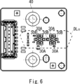
- FIG. 6 is a cross-sectional view of the substrate 40 as viewed from the direction of the arrow Ar1 in FIG. 5.
- the vehicle lamp 10 includes a light guide 20, a substrate 40 on which a first light source 30A and a second light source 30B are mounted, a heat sink 50 to which the substrate 40 is attached, a bracket 60 to which the light guide 20 is attached, an inner lens 70, an extension 80 which is a decorative member, an outer lens 90, and a housing 100.
- the light guide 20, substrate 40, heat sink 50, bracket 60, inner lens 70, and extension 80 are disposed within a lamp chamber formed by the outer lens 90 and housing 100, and are attached to the housing 100, etc.
- the inner lens 70 is made of a transparent resin such as acrylic or polycarbonate, and is configured to have an L-shape when viewed from the front as shown in FIG. 1A.
- the inner lens 70 includes a wide region A 70a and a narrow region A 70b .
- the wide region A 70a is disposed on the outer side in the vehicle width direction and extends in the vertical direction.
- the width L 70a of the wide region A 70a is, for example, 60 mm.
- the narrow region A 70b extends from the lower end of the wide region A 70a toward the inner side in the vehicle width direction.
- the width L 70b of the narrow region A 70b is, for example, 30 mm.
- the light guided by the light guide 20 disposed behind the inner lens 70 passes through the inner lens 70 (wide area A 70a and narrow area A 70b ). This causes the inner lens 70 (wide area A 70a and narrow area A 70b ) to emit light.
- the area hatched HT in FIG. 1B represents the light-emitting area.
- the light guide 20 is attached to the bracket 60 and disposed behind the inner lens 70.
- the bracket 60 is made of, for example, white resin that functions as a reflective surface, and includes a bracket body 61, left and right wall portions 62, 63 (see Figure 3) that extend from the left and right sides of the bracket body 61 toward the inner lens 70, and upper and lower wall portions 64, 65 (see Figure 4) that extend from the top and bottom sides of the bracket body 61 toward the inner lens 70.
- the light guide 20 is made of a transparent resin such as acrylic or polycarbonate, and includes three rod-shaped light guides 21A-21C arranged in parallel to one another as shown in FIG. 2.
- the rod-shaped light guides are also called light guide rods.
- rod-shaped light guides 21 when there is no need to distinguish between the rod-shaped light guides 21A-21C, they will simply be referred to as rod-shaped light guides 21.
- the rod-shaped light guide 21 guides the light emitted by the first light source 30A and the second light source 30B.
- the rod-shaped light guide 21 is a long light guide rod that guides the light incident from the light incident surface 22, which is the end face on the base end BE 21 side, toward the tip end FE 21 side, and is configured to have a three-dimensional curved shape corresponding to the shape of the inner lens 70 (here, L-shaped).
- the rod-shaped light guide 21 includes a junction portion 210 extending from the base end BE 21 side toward the front of the vehicle, a first rod-shaped light guide 211 extending from the junction portion 210 toward the front and downward diagonal direction (an example of the first direction of the present disclosure) via a first curved portion C1, and a second rod-shaped light guide 212 extending from the first rod-shaped light guide 211 toward the inside in the vehicle width direction (an example of the second direction of the present disclosure) via a second curved portion C2.
- the first rod-shaped light guiding portion 211 is disposed behind the wide region A 70a of the inner lens 70 so that light emitted from the light output surface 211a of the first rod-shaped light guiding portion 211 passes through the wide region A 70a .
- the first rod-shaped light guiding portion 211 is disposed on the vehicle rear side in the space S1 surrounded by the bracket main body 61, the left and right wall portions 62 and 63 of the bracket 60, and the inner lens 70.
- the second rod-shaped light guiding portion 212 is disposed behind the narrow region A 70b of the inner lens 70 so that light emitted from the light output surface 212a of the second rod-shaped light guiding portion 212 passes through the narrow region A 70b .
- the second rod-shaped light guiding portion 212 is disposed on the vehicle rear side in the space S2 surrounded by the bracket main body 61, the upper and lower wall portions 64 and 65 of the bracket 60, and the inner lens 70.
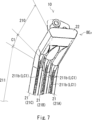
- Figure 7 is an enlarged perspective view of the vicinity of the light entrance surface 22 of the rod-shaped light guide 21 as viewed from the direction of the arrow Ar2 in Figure 2.
- the base end BE21 of the rod-shaped light guiding unit 21 includes a common light entrance surface 22.
- This light entrance surface 22 has, for example, a planar shape perpendicular to the longitudinal direction (the direction in which the rod-shaped light guiding unit 21 extends) of the rod-shaped light guiding unit 21 (see FIG. 5). Note that the light entrance surface 22 is not limited to a planar shape, and may have a curved shape or a cap shape convex toward the first light source 30A and the second light source 30B.
- the light entrance surface 22 is provided at the tip of this junction 210. By providing this junction 210, the light entering from the light entrance surface 22 (light emitted by the first light source 30A and the second light source 30B) can be made to enter the rod-shaped light guides 21A-21C evenly.
- the light guide 20 is attached to the bracket 60 with the light entrance surface 22 facing the first light source 30A and the second light source 30B (see FIG. 5).
- the cross-sectional shapes of the first rod-shaped light guiding section 211 and the second rod-shaped light guiding section 212 are set to be different from each other so that the angular range ⁇ 2 (see FIG. 8C) of light Ray2 guided through the first rod-shaped light guiding section 211 and output from the light output surface 211a of the first rod-shaped light guiding section 211 is larger than the angular range ⁇ 1 (see FIG. 8A) of light Ray1 guided through the second rod-shaped light guiding section 212 and output from the light output surface 212a of the second rod-shaped light guiding section 212.
- ⁇ 2 see FIG. 8C
- ⁇ 1 see FIG. 8A
- FIG. 12 shows the cross-sectional shape of the rod-shaped light guide section 21.
- the cross-sectional shape CS211 of the first rod-shaped light guiding section 211 is a sector shape that is line-symmetric with respect to the optical axis AX211 of the first rod-shaped light guiding section 211.
- the first rod-shaped light guiding section 211 includes a light output surface 211a, a first reflecting surface 211b on the opposite side thereof, and a pair of second reflecting surfaces 211c, 211d on both sides thereof.
- the cross-sectional shape CS211 of the first rod-shaped light guiding section 211 does not have to be a perfect sector shape, and may be approximately a sector shape.
- the light output surface 211a is disposed on the front side (vehicle front side) with the inner lens 70 facing it.
- the first reflecting surface 211b is disposed on the back side (vehicle rear side) with the bracket 60 (bracket body 61) facing it.
- the cross-sectional shape of the light-emitting surface 211a is a convex arc shape facing the front side (the light irradiation direction; downward in Figure 3).
- the cross-sectional shape of the first reflecting surface 211b is a straight line intersecting (orthogonal to) the optical axis AX211 of the first rod-shaped light guiding portion 211.
- the length L211b of the first reflecting surface 211b is shorter than the length L211a of the light output surface 211a.
- the first reflecting surface 211b includes an optical element LC1 (see FIG. 7) configured to internally reflect (total reflect) the light that is guided through the first rod-shaped light guiding section 211 and enters the first reflecting surface 211b, causing it to exit from the light exit surface 211a.
- a plurality of optical elements LC1 are provided in the longitudinal direction of the first rod-shaped light guiding section 211.
- the optical element LC1 is, for example, a lens cut (for example, a V-groove).
- the cross-sectional shape of the second reflecting surface 211c is linear, connecting one end of the light-emitting surface 211a to one end of the first reflecting surface 211b (see FIG. 3).
- the cross-sectional shape of the second reflecting surface 211d is linear, connecting the other end of the light-emitting surface 211a to the other end of the first reflecting surface 211b (see FIG. 3).
- first rod-shaped light guides 211 are arranged adjacent to each other in the left-right direction (vehicle width direction).
- adjacent first rod-shaped light guides 211 are connected to each other via connecting portions 211e and 211f.
- connecting portions 211e and 211f are so-called connecting portions that do not have any optical function.
- the cross-sectional shape CS212 of the second rod-shaped light guiding section 212 is a ginkgo shape that is line-symmetrical with respect to the optical axis AX212 of the second rod-shaped light guiding section 212.
- the second rod-shaped light guiding section 212 includes a light output surface 212a, a first reflecting surface 212b on the opposite side thereof, and a pair of second reflecting surfaces 212c, 212d on both sides thereof.
- the cross-sectional shape CS212 of the second rod-shaped light guiding section 212 does not have to be a perfect ginkgo shape, and may be approximately ginkgo-shaped.
- the light output surface 212a is disposed on the front side (vehicle front side) with the inner lens 70 facing it.
- the first reflecting surface 212b is disposed on the back side (vehicle rear side) with the bracket 60 (bracket body 61) facing it.
- the cross-sectional shape of the light output surface 212a is a convex arc shape toward the front side (light irradiation direction, leftward in FIG. 4).
- the diameter of the light output surface 212a of the second rod-shaped light guiding section 212 (see distance L 212a in FIG. 4) is approximately equal to the diameter of the light output surface 211a of the first rod-shaped light guiding section 211 (see distance L 211a in FIG. 3).
- the curvature of the light output surface 212a of the second rod-shaped light guiding section 212 and the curvature of the light output surface 211a of the first rod-shaped light guiding section 211 are the same, but may be different from each other.
- the cross-sectional shape of the first reflecting surface 212b is a straight line intersecting (orthogonal to) the optical axis AX 212 of the second rod-shaped light guiding portion 212.
- the length L 212b of the first reflecting surface 212b is shorter than the length L 212a of the light output surface 212a.
- the first reflecting surface 212b includes an optical element LC2 configured to internally reflect (total reflect) the light that is guided through the second rod-shaped light guiding section 212 and enters the first reflecting surface 212b, causing the light to exit from the light exit surface 212a.
- a plurality of optical elements LC2 are provided in the longitudinal direction of the second rod-shaped light guiding section 212.
- the optical elements LC2 are, for example, lens cuts (e.g., V-grooves) like the optical element LC1.
- the cross-sectional shape of second reflecting surface 212c is a convex arc shape toward the inside of second rod-shaped light guiding section 212, connecting one end of light output surface 212a to one end of first reflecting surface 212b (see FIG. 4).
- the cross-sectional shape of second reflecting surface 212d is a convex arc shape toward the inside of second rod-shaped light guiding section 212, connecting the other end of light output surface 212a to the other end of first reflecting surface 212b (see FIG. 4).
- three second rod-shaped light guiding sections 212 are arranged adjacent to each other in the vertical direction.
- adjacent second rod-shaped light guiding sections 212 are connected to each other via connecting sections 212e and 212f.
- connecting sections 212e and 212f are so-called linking sections that do not have any optical function.
- the second curved portion C2 is a curved rod-shaped light guiding portion (gradual change portion) that connects the first rod-shaped light guiding portion 211 and the second rod-shaped light guiding portion 212.
- the second curved portion C2 is an example of a third rod-shaped light guiding portion of the present disclosure.
- the cross-sectional shape CS C2 of the second curved portion C2 is a shape that gradually changes from a fan shape to a ginkgo shape from the first rod-shaped light guiding portion 211 to the second rod-shaped light guiding portion 212.
- a step portion is prevented from being formed between the first rod-shaped light guiding portion 211 and the second rod-shaped light guiding portion 212, and therefore, the second curved portion C2 can be prevented from emitting a point light or the like due to the light guided in the rod-shaped light guiding portion 21 being incident on the step portion.
- the first light source 30A is, for example, a semiconductor light-emitting element such as an LED that emits amber light.
- the first light source 30A has a light-emitting surface (for example, a rectangular light-emitting surface of 1 mm square).
- a light-emitting surface for example, a rectangular light-emitting surface of 1 mm square.
- four first light sources 30A are mounted on the upper and lower tiers of the substrate 40 (light source mounting surface) while being arranged in a row in the left-right direction (vehicle width direction). Note that the number of first light sources 30A is not limited to four, and may be one or more.
- the second light source 30B is, for example, a semiconductor light emitting element such as an LED that emits white light.
- the second light source 30B has a light emitting surface (for example, a rectangular light emitting surface of 1 mm square).
- six second light sources 30B are mounted in the middle of the substrate 40 (light source mounting surface) while being arranged in a row in the left-right direction (vehicle width direction).
- the number of second light sources 30B is not limited to six, and may be one or more.
- the substrate 40 is fixed to a bracket 60 or the like in a state in which the first light source 30A (light emitting surface) and the second light source 30B (light emitting surface) mounted on the substrate 40 face the light entrance surface 22 of the rod-shaped light guiding unit 21 (see FIG. 5 ).
- a dotted line DL 22 indicates the outline of the light entrance surface 22 of the rod-shaped light guiding unit 21.
- a turn signal can be achieved by turning on the first light source 30A that emits amber light and turning off the second light source 30B that emits white light.
- the light path of the light emitted by the first light source 30A is as follows: When the first light source 30A is turned on, the light emitted by the first light source 30A enters the rod-shaped light guiding section 21 from the light entrance surface 22 of the rod-shaped light guiding section 21, and is guided through the junction section 210 , the first curved section C1, the first rod-shaped light guiding section 211, the second curved section C2, and the second rod-shaped light guiding section 212 in this order toward the tip section FE21 of the rod-shaped light guiding section 21 while repeatedly undergoing internal reflection (total reflection) within the rod-shaped light guiding section 21.
- a portion of the light guided through the first rod-shaped light guide 211 is internally reflected (diffusely reflected) by the first reflecting surface 211b (optical element LC1) of the first rod-shaped light guide 211 and exits from the light exit surface 211a of the first rod-shaped light guide 211.
- a portion of the light guided through the second curved portion C2 is internally reflected (diffusely reflected) by a first reflecting surface (optical element) (not shown) of the second curved portion C2 and exits from the light exit surface of the second curved portion C2.
- a portion of the light guided through the second rod-shaped light guide 212 is internally reflected (diffusely reflected) by the first reflecting surface 212b (optical element LC2) of the second rod-shaped light guide 212 and exits from the light exit surface 212a of the second rod-shaped light guide 212.
- the light emitted from each light output surface of the rod-shaped light guiding section 21 passes through the inner lens 70 and the outer lens 90 and is irradiated within a predetermined angle range in front of the vehicle. At this time, some of the light passes directly through the inner lens 70 and the outer lens 90, while the other part of the light is reflected by the left and right wall sections 62, 63 and the top and bottom wall sections 64, 65 of the bracket 60, and then passes through the inner lens 70 and the outer lens 90.
- the turn signal is generated by the light (amber light) that passes through the inner lens 70 and the outer lens 90 and is projected within a specified angle range in front of the vehicle.
- the light emitted mainly from the light output surface 211a of the first rod-shaped light guiding portion 211 passes through the wide region A 70a (see Figs. 1A and 3) of the inner lens 70, causing the wide region A 70a to emit light.
- the entire wide region A 70a emits light uniformly (almost uniformly). This point will be described below in comparison with a comparative example.
- the comparative example is an example in which a second rod-shaped light guiding section 212 with a ginkgo-shaped cross-sectional shape is used instead of a first rod-shaped light guiding section 211 with a fan-shaped cross-sectional shape. Other than that, it is the same as this embodiment.
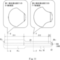
- FIG. 8A is a diagram showing the angular range ⁇ 1 of light emitted from the light output surface 212a of the second rod-shaped light guide 212 (one piece) of the comparative example.
- FIG. 8B is a diagram showing the range of light emitted from the light output surface 212a of the second rod-shaped light guide 212 (three pieces) of the comparative example.
- FIG. 8C is a diagram showing the angular range ⁇ 2 of light emitted from the light output surface of the first rod-shaped light guide 211 (one piece) of the embodiment.
- FIG. 8D is a diagram showing the range of light emitted from the light output surface of the first rod-shaped light guide 211 (three pieces) of the embodiment.
- a relatively dark dark portion occurs in a part of the wide region A 70a (for example, see the circular region indicated by the symbol D1 in FIG. 8A). This is because, in the comparative example, as shown in FIG. 8A, the width L 70a of the wide region A 70a is wider than the angular range ⁇ 1 (see FIG.
- the occurrence of a relatively dark portion in a portion of the wide region A 70a (for example, see the circular region indicated by the symbol D1 in Fig. 8C) can be suppressed.
- the angle range ⁇ 2 (see Fig. 8C) of the light Ray2 emitted from the light output surface 211a of the first rod-shaped light guiding unit 211 is larger than the angle range ⁇ 1 (see Fig.
- the light emitted mainly from the light output surface 212a of the second rod-shaped light guiding section 212 passes through the narrow region A 70b (see FIGS. 1A and 4) of the inner lens 70, causing the narrow region A 70b to emit light.
- the width L 70b (see FIGS. 1A and 4) of the narrow region A 70b of the inner lens 70 corresponds to the angular range ⁇ 1 (see FIG. 8A) of the light emitted from the light output surface 212a of the second rod-shaped light guiding section 212, which has a ginkgo-shaped cross section, the entire narrow region A 70b also emits light uniformly (approximately uniformly).
- the inner lens 70 when realizing a turn signal lamp, the inner lens 70 (wide region A 70a and narrow region A 70b ) can be made to emit light uniformly (or approximately uniformly) (no relatively dark areas are generated in parts of the wide region A 70a ).
- a DRL lamp can be realized by turning off the first light source 30A that emits amber light and turning on the second light source 30B that emits white light at a first brightness.
- the light emitted by the second light source 30B follows the same optical path as the light emitted by the first light source 30A in the turn lamp, exits from each light exit surface of the rod-shaped light guide 21 (the first rod-shaped light guide 211, the second curved portion C2, and the second rod-shaped light guide 212), and is irradiated within a predetermined angle range in front of the vehicle through the inner lens 70 and the outer lens 90.
- the DRL lamp is realized by the light (white light with a first brightness) that is irradiated within a predetermined angle range in front of the vehicle through the inner lens 70 and the outer lens 90. At that time, for the same reason as the turn lamp, the entire wide area A 70a and the entire narrow area A 70b of the inner lens 70 emit light uniformly (almost uniformly).
- the inner lens 70 can be made to emit light uniformly (or approximately uniformly) (no relatively dark areas are generated in parts of the wide region A 70a ).
- a position lamp can be realized by turning off the first light source 30A that emits amber light and turning on the second light source 30B that emits white light at a second brightness that is darker than the first brightness.
- the light emitted by the second light source 30B follows the same optical path as the light emitted by the first light source 30A in the turn lamp, exits from each light exit surface of the rod-shaped light guide 21 (the first rod-shaped light guide 211, the second curved portion C2, and the second rod-shaped light guide 212), and is irradiated within a predetermined angle range in front of the vehicle through the inner lens 70 and the outer lens 90.
- the position lamp is realized by the light (white light of the second brightness) that is irradiated within a predetermined angle range in front of the vehicle through the inner lens 70 and the outer lens 90. At that time, for the same reason as the turn lamp, the entire wide area A 70a and the entire narrow area A 70b of the inner lens 70 emit light uniformly (almost uniformly).
- the inner lens 70 can be made to emit light uniformly (or approximately uniformly) (no relatively dark areas are generated in parts of the wide region A 70a ).
- the inner lens 70 (wide region A 70a and narrow region A 70b ) can be made to emit light uniformly (or approximately uniformly) (no relatively dark areas are generated in parts of the wide region A 70a ).
- the cross-sectional shape CS 211 (see FIGS. 3 and 12 ) of the first rod-shaped light guiding portion 211 and the cross-sectional shape CS 212 (see FIGS. 4 and 12 ) of the second rod-shaped light guiding portion 212 are set to be different from each other so that an angular range ⁇ 2 (see FIG. 8C ) of light guided inside the first rod-shaped light guiding portion 211 and outputting from the light output surface 211 a of the first rod-shaped light guiding portion 211 is larger than an angular range ⁇ 1 (see FIG.
- the cross-sectional shape CS 211 of the first rod-shaped light guiding portion 211 is set to be different from each other so that the light outputting from the light output surface 211 a of the first rod-shaped light guiding portion 211 transmits through the wide region A 70 a.
- the second rod-shaped light guiding section 212 is arranged behind narrow region A 70b so that light exiting from the light exit surface 212a of the second rod-shaped light guiding section 212 passes through narrow region A 70b ( see FIG. 4).
- the light guide 20 includes three rod-shaped light guides 21A to 21C, but this is not limited to the above.
- the light guide 20 may include one or more rod-shaped light guides.
- the inner lens 70 is L-shaped and the rod-shaped light guide 21 is three-dimensionally curved to correspond to the shape (L-shape) of the inner lens 70, but this is not limiting.
- the inner lens 70 may be linear, and the rod-shaped light guide 21 may be linear to correspond to the shape (linear shape) of the inner lens 70.
- FIG. 9 shows a first modified example of the rod-shaped light guide 21 and the inner lens 70.
- the first rod-shaped light guide 211 is disposed on the light source side (first light source 30A, second light source 30B side) and the second rod-shaped light guide 212 is disposed on the opposite light source side (see Figs. 2 and 9), but this is not limited thereto.
- the second rod-shaped light guide 212 may be disposed on the light source side (first light source 30A, second light source 30B side) and the first rod-shaped light guide 211 may be disposed on the opposite light source side.
- Fig. 10 shows a second modified example of the rod-shaped light guide 21 and the inner lens 70. The gradually changing portion C2' in Fig.
- FIG. 10 shows a third modified example of the rod-shaped light guide 21 and the inner lens 70.
Landscapes
- Engineering & Computer Science (AREA)
- General Engineering & Computer Science (AREA)
- Physics & Mathematics (AREA)
- Optics & Photonics (AREA)
- General Physics & Mathematics (AREA)
- Microelectronics & Electronic Packaging (AREA)
- Planar Illumination Modules (AREA)
- Non-Portable Lighting Devices Or Systems Thereof (AREA)
Priority Applications (1)
| Application Number | Priority Date | Filing Date | Title |
|---|---|---|---|
| CN202480031693.2A CN121100249A (zh) | 2023-05-11 | 2024-05-10 | 车灯和光导体 |
Applications Claiming Priority (2)
| Application Number | Priority Date | Filing Date | Title |
|---|---|---|---|
| JP2023-078376 | 2023-05-11 | ||
| JP2023078376A JP2024162651A (ja) | 2023-05-11 | 2023-05-11 | 車両用灯具、及び導光体 |
Publications (1)
| Publication Number | Publication Date |
|---|---|
| WO2024232424A1 true WO2024232424A1 (ja) | 2024-11-14 |
Family
ID=93430166
Family Applications (1)
| Application Number | Title | Priority Date | Filing Date |
|---|---|---|---|
| PCT/JP2024/017332 Ceased WO2024232424A1 (ja) | 2023-05-11 | 2024-05-10 | 車両用灯具、及び導光体 |
Country Status (3)
| Country | Link |
|---|---|
| JP (1) | JP2024162651A (https=) |
| CN (1) | CN121100249A (https=) |
| WO (1) | WO2024232424A1 (https=) |
Citations (5)
| Publication number | Priority date | Publication date | Assignee | Title |
|---|---|---|---|---|
| JP2013222657A (ja) * | 2012-04-18 | 2013-10-28 | Ichikoh Ind Ltd | 車両用灯具 |
| JP2015154120A (ja) * | 2014-02-11 | 2015-08-24 | 三菱電機株式会社 | 照明装置及びそれを用いたイメージセンサ |
| JP2017033836A (ja) * | 2015-08-04 | 2017-02-09 | 株式会社小糸製作所 | 車両用灯具 |
| JP2018156868A (ja) * | 2017-03-17 | 2018-10-04 | スタンレー電気株式会社 | 車両用灯具 |
| JP2020068110A (ja) * | 2018-10-24 | 2020-04-30 | スタンレー電気株式会社 | 車両用灯具 |
-
2023
- 2023-05-11 JP JP2023078376A patent/JP2024162651A/ja active Pending
-
2024
- 2024-05-10 WO PCT/JP2024/017332 patent/WO2024232424A1/ja not_active Ceased
- 2024-05-10 CN CN202480031693.2A patent/CN121100249A/zh active Pending
Patent Citations (5)
| Publication number | Priority date | Publication date | Assignee | Title |
|---|---|---|---|---|
| JP2013222657A (ja) * | 2012-04-18 | 2013-10-28 | Ichikoh Ind Ltd | 車両用灯具 |
| JP2015154120A (ja) * | 2014-02-11 | 2015-08-24 | 三菱電機株式会社 | 照明装置及びそれを用いたイメージセンサ |
| JP2017033836A (ja) * | 2015-08-04 | 2017-02-09 | 株式会社小糸製作所 | 車両用灯具 |
| JP2018156868A (ja) * | 2017-03-17 | 2018-10-04 | スタンレー電気株式会社 | 車両用灯具 |
| JP2020068110A (ja) * | 2018-10-24 | 2020-04-30 | スタンレー電気株式会社 | 車両用灯具 |
Also Published As
| Publication number | Publication date |
|---|---|
| JP2024162651A (ja) | 2024-11-21 |
| CN121100249A (zh) | 2025-12-09 |
Similar Documents
| Publication | Publication Date | Title |
|---|---|---|
| JP4930787B2 (ja) | 車両用灯具、及び、車両用灯具に用いられる導光レンズ | |
| KR102948184B1 (ko) | 자동차 그릴의 조명 장치 | |
| JP6560514B2 (ja) | 車両用灯具 | |
| JP6264789B2 (ja) | 車両用灯具 | |
| JP7081977B2 (ja) | 車両用灯具 | |
| JP6114025B2 (ja) | 車両用灯具 | |
| CN111473296B (zh) | 车辆用灯具单元 | |
| JP2020027690A (ja) | 車輌用灯具 | |
| CN120576344A (zh) | 车辆用灯具 | |
| WO2024232424A1 (ja) | 車両用灯具、及び導光体 | |
| JP2024131652A (ja) | 車両用灯具 | |
| JP7633136B2 (ja) | 車両用灯具 | |
| JP7217301B2 (ja) | 車両用灯体装置 | |
| WO2023210343A1 (ja) | 車両用灯具 | |
| CN110553219B (zh) | 车辆用灯具 | |
| EP3561374B1 (en) | Vehicular lamp | |
| JP7702370B2 (ja) | 車両用灯具 | |
| JP7756044B2 (ja) | 車両用灯具 | |
| JP7818470B2 (ja) | 車両用灯具 | |
| JP7574651B2 (ja) | 車両用インナーレンズ、車両用灯具 | |
| CN110553223A (zh) | 车辆用灯具 | |
| JP2023092728A (ja) | 車両用灯具及びレンズ体 | |
| JP7347968B2 (ja) | 車両用灯具 | |
| JP7255951B2 (ja) | 車両用灯具ユニット及び車両用灯具 | |
| JP7023779B2 (ja) | 車両用灯具 |
Legal Events
| Date | Code | Title | Description |
|---|---|---|---|
| 121 | Ep: the epo has been informed by wipo that ep was designated in this application |
Ref document number: 24803533 Country of ref document: EP Kind code of ref document: A1 |
|
| NENP | Non-entry into the national phase |
Ref country code: DE |