WO2024232201A1 - ボールねじ装置 - Google Patents
ボールねじ装置 Download PDFInfo
- Publication number
- WO2024232201A1 WO2024232201A1 PCT/JP2024/014081 JP2024014081W WO2024232201A1 WO 2024232201 A1 WO2024232201 A1 WO 2024232201A1 JP 2024014081 W JP2024014081 W JP 2024014081W WO 2024232201 A1 WO2024232201 A1 WO 2024232201A1
- Authority
- WO
- WIPO (PCT)
- Prior art keywords
- groove surface
- ball
- raceway
- screw shaft
- groove
- Prior art date
- Legal status (The legal status is an assumption and is not a legal conclusion. Google has not performed a legal analysis and makes no representation as to the accuracy of the status listed.)
- Ceased
Links
Images





Classifications
-
- F—MECHANICAL ENGINEERING; LIGHTING; HEATING; WEAPONS; BLASTING
- F16—ENGINEERING ELEMENTS AND UNITS; GENERAL MEASURES FOR PRODUCING AND MAINTAINING EFFECTIVE FUNCTIONING OF MACHINES OR INSTALLATIONS; THERMAL INSULATION IN GENERAL
- F16H—GEARING
- F16H25/00—Gearings comprising primarily only cams, cam-followers and screw-and-nut mechanisms
- F16H25/18—Gearings comprising primarily only cams, cam-followers and screw-and-nut mechanisms for conveying or interconverting oscillating or reciprocating motions
- F16H25/20—Screw mechanisms
- F16H25/22—Screw mechanisms with balls, rollers, or similar members between the co-operating parts; Elements essential to the use of such members
- F16H25/2204—Screw mechanisms with balls, rollers, or similar members between the co-operating parts; Elements essential to the use of such members with balls
- F16H25/2214—Screw mechanisms with balls, rollers, or similar members between the co-operating parts; Elements essential to the use of such members with balls with elements for guiding the circulating balls
- F16H25/2223—Cross over deflectors between adjacent thread turns, e.g. S-form deflectors connecting neighbouring threads
Definitions
- This disclosure relates to a ball screw device.
- the ball screw device includes a nut, a screw shaft inserted into the nut, a number of balls arranged between the nut and the screw shaft, and a circulation part.
- An inner circumferential raceway surface is formed on the inner circumferential surface of the nut.
- An outer circumferential raceway surface facing the inner circumferential raceway surface is formed on the outer circumferential surface of the screw shaft.
- a spiral track is formed between the inner circumferential raceway surface and the outer circumferential raceway surface.
- the balls are arranged on the track and move in a spiral direction along the track.
- the circulation part returns the balls that have moved from one end of the track to the other end of the track to one end of the track.
- One example of a circulation part is a top that returns the balls one lead.
- a recess is formed on the outer circumferential surface of the screw shaft, recessed radially inward.
- a ball is inserted into the recess and attached to the screw shaft.
- the ball has an outer diameter surface facing radially outward, and a circulation groove surface recessed radially inward from the outer diameter surface.
- the circulation groove surface is an S-groove surface that forms an S-shape when viewed from the radial outside. The balls move radially inward within the S-groove surface of the ball, climbing over the threads of the nut.
- This disclosure has been made in consideration of the above, and aims to provide a ball screw device that ensures smooth rolling of the balls and prevents damage to the bearings.
- a ball screw device includes a nut having an inner circumferential raceway surface on its inner circumferential surface, a screw shaft inserted into the nut and having an outer circumferential raceway surface on its outer circumferential surface, a plurality of balls arranged on a track between the outer circumferential raceway surface and the inner circumferential raceway surface, and at least one or more tops for circulating the balls.
- the outer circumferential surface of the screw shaft is provided with at least one recess that is recessed radially inward and accommodates the tops.
- the inner circumferential surface of the recess is provided with two screw shaft side openings of the outer circumferential raceway surface that open toward the tops.
- the top has a pair of top side openings that open from the outer circumferential surface of the top and connect with the screw shaft side opening, a circulation groove surface that connects with each of the pair of top side openings and whose internal space constitutes a circulation path, and a pair of tangs that are arranged radially outward of the circulation groove surface and protrude toward the top side opening.
- the tip of the tang is positioned radially outward of the imaginary spiral that connects the centers of the balls that roll on the raceway.
- a ball that enters the top side opening from the outer peripheral raceway surface comes into contact with the tip of the tang.
- the tip of the tang also comes into contact with a portion of the ball that is radially outward from the center of the ball. This changes the ball's path radially inward, ensuring that the ball moves radially inward. This prevents the ball from becoming pinched between the circulation groove surface and the inner peripheral raceway surface of the nut, ensuring smooth rolling of the ball. Damage to the groove shoulder of the circulation groove surface is also avoided.
- the tang has an inner diameter surface that faces radially inward.
- the inner diameter surface is inclined so that it is gradually positioned radially inward as it moves away from the tip.
- the tip is disposed on the inner circumferential raceway surface of the nut.
- the circulation groove surface of the ball screw device is an S-shaped groove surface.
- the S-shaped groove surface is disposed near the top side opening and has a spiral region extending along the spiral direction in which the track extends, and a curved region adjacent to the spiral region that gradually starts to deviate from the spiral direction.
- the tip portion may be disposed radially outward from the spiral region.
- the circulation groove surface of the ball screw device is an S-shaped groove surface.
- the S-shaped groove surface is disposed near the top side opening and has a spiral region extending along the spiral direction in which the track extends, and a curved region adjacent to the spiral region that gradually starts to deviate from the spiral direction.
- the tip portion may be disposed radially outward of the curved region.
- the circulation groove surface is an S-shaped groove surface.
- the recess and the top When viewed from the radial outside of the screw shaft, the recess and the top have a longer length in a direction intersecting the axial direction than in an axial direction parallel to the screw shaft.
- the ratio of the cross direction on the S-shaped groove surface is increased.
- the curvature of the S-shaped groove surface is gentler.
- the ball moves smoothly on the S-shaped groove surface.
- the circulation groove surface of the ball screw device may extend in a reverse helical direction opposite to the helical direction in which the track extends.
- the height of the threads on the outer peripheral raceway surface is greater than the height of the threads on the inner peripheral raceway surface.
- the height of the threads on the outer raceway surface is increased, making it difficult for the balls to ride up onto the groove shoulders of the outer raceway surface. Furthermore, according to the above configuration, the bottom of the outer raceway surface is deep. Therefore, when the balls move from the outer raceway surface to the circulation groove surface of the top, the step amount (radial movement amount) between the outer raceway surface and the circulation groove surface of the top is small. On the other hand, when a top is provided on the nut, the bottom of the inner raceway surface is shallow, so the step amount (radial movement amount) between the inner raceway surface and the circulation groove surface of the top is large. Therefore, according to the present disclosure, the radial movement amount of the balls is kept small, and the balls move smoothly along the circulation groove surface.
- the circulation groove surface has a pair of inlet/outlet groove surfaces that are arranged at both ends in the extension direction of the circulation groove surface and extend circumferentially from the top side opening, and a concave surface that is arranged between the pair of inlet/outlet groove surfaces and into which the balls sink radially inward.
- the circulation groove surface has a concave surface on the radially inner side into which the balls sink.
- the concave surface is flat when viewed from the axial direction.
- a conventional concave surface When viewed from the axial direction, a conventional concave surface is recessed radially inward at the center of the S-shape compared to both ends of the S-shape in which the concave surface extends, resulting in a concave shape.
- the concave surface of the above configuration is linear when viewed from the axial direction, so the bending angle of the ball when it enters the concave surface is smaller. This allows the ball to roll more smoothly.
- the groove shape of the top side opening is larger than the groove shape of the screw shaft side opening.
- the ball screw device disclosed herein ensures smooth rolling of the balls. It also prevents damage to the groove shoulder of the circulation groove surface.
- FIG. 1 is a cross-sectional view of a brake caliper according to an embodiment.
- FIG. 2 is a perspective view of a top and a recess of the ball screw device according to the embodiment.
- FIG. 3 is an enlarged view of the recess and the piece according to the embodiment, viewed from the radially outer side.
- FIG. 4 is a schematic cross-sectional view showing a cross section taken along the center of the S-shaped groove surface.
- FIG. 5 is a view of an opening (screw shaft side opening) of an outer circumferential raceway surface provided on a second opposing surface of the recess, as viewed from the recess.
- FIG. 6 is a diagram showing a state in which the top has moved radially outward from the state shown in FIG. FIG.
- FIG. 7 is an enlarged view of the recess and the piece in FIG. 3, which are arranged at the lower left.
- FIG. 8 is a cross-sectional view taken along line VIII-VIII in FIG.
- FIG. 9 is a cross-sectional view of the ball screw device of Comparative Example 1 taken along the center of the groove width of the S-groove surface.
- FIG. 10 is a diagram illustrating an abstract view of a frame of Comparative Example 2.
- FIG. 11 is a diagram illustrating an abstract view of a frame according to an embodiment.
- FIG. 12 is a schematic diagram of a top of the first modified example viewed from the radially outer side.
- FIG. 13 is a schematic diagram of a cross section of a piece according to the second modification taken along the circulation groove surface.
- FIG. 14 is a schematic cross-sectional view of a piece according to the third modification taken along the circulation groove surface.
- FIG. 15 is a schematic diagram of a cross section of a piece according to the fourth modification taken along the circulation groove surface.
- FIG. 16 is a schematic diagram of a top according to the fifth modification, viewed from the radially outer side.
- FIG. 17 is a schematic diagram of a top according to the sixth modification, viewed from the radially outer side.
- Figure 1 is a cross-sectional view of a brake caliper according to an embodiment.
- the brake caliper 100 is a device for suppressing the rotational movement of a wheel (not shown) by sandwiching a brake disc 101, which rotates with the wheel, between two brake pads 102, 103.
- the brake caliper 100 includes the brake disc 101, two brake pads 102, 103, an electric actuator 104 that operates the brake pad 102, and a housing 120.
- the electric actuator 104 includes a motor (not shown) that generates rotational motion, a reduction gear 110 that decelerates the rotational motion, and a ball screw device 1 that converts the rotational motion into linear motion.
- a motor not shown
- a reduction gear 110 that decelerates the rotational motion
- a ball screw device 1 that converts the rotational motion into linear motion.
- the direction parallel to the axis O1 of the screw shaft 2 of the ball screw device 1 is referred to as the axial direction.
- the direction in which the brake disc 101 is positioned as viewed from the ball screw device 1 is referred to as the first direction X1
- the direction opposite to the first direction X1 is referred to as the second direction X2.
- the reduction gear 110 is a planetary gear mechanism.
- the reduction gear 110 includes an input shaft 111, a sun gear 112, a ring gear 113, a plurality of planetary gears 114, a plurality of transmission shafts 115, and a carrier 116.
- the rotational motion of the motor is input to the input shaft 111.
- the input shaft 111 extends in the axial direction.
- the axis O2 of the input shaft 111 is located on an extension of the axis O1.
- the sun gear 112 passes through the input shaft 111 and is fixed to the input shaft 111 so as not to rotate.
- the ring gear 113 is an internal gear centered on the axis O2.
- the outer peripheral surface of the ring gear 113 is fitted into the housing 120.
- the planetary gear 114 is disposed between the sun gear 112 and the ring gear 113, and is meshed with the sun gear 112 and the ring gear 113.
- the planetary gear 114 is passed through the transmission shaft 115.
- the planetary gear 114 is supported so as to be freely rotatable about the transmission shaft 115.
- the carrier 116 is an annular part centered on the axis O1.
- the outer peripheral surface of the carrier 116 is fitted into the bearing 117.
- the carrier 116 is supported by the housing 120 so as to be freely rotatable.
- the connecting portion 10 of the screw shaft 2 is inserted into the center of the carrier 116.
- the carrier 116 and the connecting portion 10 are spline-fitted.
- the transmission shaft 115 passes through the carrier 116 at a position eccentric radially outward from the center of the carrier 116.
- the ball screw device 1 comprises a screw shaft 2, a nut 3, balls 4 (not shown in FIG. 1, see FIG. 4), and a number of pieces 5 (only one is shown in FIG. 1).
- the screw shaft 2 comprises a connecting portion 10 that connects to the carrier 116, and a screw shaft body 11 that is disposed in a first direction X1 with respect to the connecting portion 10 and inserted into the nut 3.
- the outer peripheral surface of the screw shaft body 11 is provided with an outer peripheral raceway surface 13 that extends in the spiral direction, and a number of recesses 14 (only one is shown in FIG. 1) that are recessed radially inward.
- the nut 3 is formed in a cylindrical shape with a bottom.
- the nut 3 has a cylindrical nut body 6 and a lid portion 7 that closes the opening of the nut body 6.
- An inner circumferential raceway surface 6a that faces the outer circumferential raceway surface 13 is provided on the inner circumferential surface of the nut body 6.
- a spiral raceway 8 is formed between the outer circumferential raceway surface 13 and the inner circumferential raceway surface 6a.
- a plurality of balls 4 are arranged on this raceway 8.
- the outer peripheral surface 6b of the nut body 6 abuts against the support surface 121 of the housing 120.
- the outer peripheral surface 6b of the nut body 6 and the support surface 121 each have a circular shape centered on the axis O1.
- a small gap is provided between the support surface 121 and the outer peripheral surface 6b of the nut body 6 so that the nut 3 can slide freely.
- the support surface 121 supports the nut 3 so that it can slide freely in the axial direction.
- a rotation prevention member (not shown) is provided on the outer peripheral surface 6b of the nut body 6. This rotation prevention member prevents the nut 3 from rotating around the axis O1.
- the cover portion 7 closes the opening of the nut body 6 in the first direction X1.
- the surface 7a of the cover portion 7 facing the first direction X1 is in contact with the brake pad 102.
- the brake pad 102 moves in the first direction X1.
- the brake pad 102 presses the brake disc 101 in the first direction X1, and the brake disc 101 comes into contact with the brake pad 103.
- the brake disc 101 is clamped between the brake pads 102 and 103, and the rotation of the wheel (not shown) is restricted.
- the top 5 is a circulation device that returns the ball 4, which has moved one lead on the track 8, by one lead. Also, one top 5 is attached to one recess 14. Note that in this disclosure, there is no particular restriction on the method of fixing the top 5 to the recess 14. In other words, the top 5 may or may not be fixed to the recess 14. Therefore, in this disclosure, the top 5 may be loosely fitted into the recess 14. Alternatively, the top 5 may be fitted into the recess 14 with a tightening margin. Alternatively, the top 5 may be glued to the recess 14. Additionally, the top 5 may be fixed to the recess 14 by crimping. In this way, there is no particular restriction on whether the top 5 is fixed or not.
- the multiple links 5 are each arranged in a different direction from the axis O1. This allows the load acting on the screw shaft 2 from the nut 3 via the balls 4 to be evenly distributed in the circumferential direction. It is more preferable that the multiple links 5 are arranged at equal intervals in the circumferential direction.
- FIG. 2 is an oblique view of the top and recess of the ball screw device of the embodiment.
- the top 5 has an S-shaped groove surface 21, a pair of top-side openings 32, 32 opening from the S-shaped groove surface 21, and a pair of tangs 40, 40 protruding toward the top-side opening 32. Details of the recess 14 and the top 5 are described below.
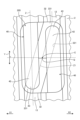
- Figure 3 is an enlarged view of the recess and the link of the embodiment as viewed from the radial outside.
- the direction perpendicular to the axis O1 as viewed from the radial outside is referred to as the intersecting direction Y.
- the direction parallel to the imaginary line Z extending along the track 8 is referred to as the spiral direction.
- the recess 14 has an inner circumferential surface 14b.
- the inner circumferential surface 14b has a pair of first opposing surfaces 15, 15 and a pair of second opposing surfaces 16, 16.
- the first opposing surfaces 15 are surfaces that extend in the transverse direction Y when viewed from the radial outside.
- the pair of first opposing surfaces 15, 15 face each other in the axial direction.
- the first opposing surfaces 15 extend linearly when viewed from the radial outside.
- the second opposing surfaces 16 are surfaces extending in the axial direction.
- the pair of second opposing surfaces 16, 16 face each other in the transverse direction Y.
- the pair of second opposing surfaces 16 are parallel to the axial direction (see axis O1).
- the length from one end to the other end of the first opposing surface 15 in the transverse direction Y is greater than the length from one end to the other end of the second opposing surface 16 in the axial direction.
- the top 5 is formed point symmetrically with respect to the center C (see FIG. 3).
- the top 5 has an outer peripheral surface 24 that is annular with the center C as the center.
- the outer peripheral surface 24 has a pair of first side surfaces 25, 25 that face the pair of first opposing surfaces 15, 15, and a pair of second side surfaces 26, 26 that face the pair of second opposing surfaces 16, 16.
- the outer shape (outer peripheral surface 24) of the top 5 has the same shape as the inner shape (inner peripheral surface 14b) of the recess 14.
- the first side surface 25 extends linearly in the transverse direction Y, just like the first opposing surface 15.
- the second side surface 26 extends linearly in the axial direction, just like the second opposing surface 16.
- the length from one end to the other end of the first side surface 25 in the transverse direction Y is greater than the length from one end to the other end of the second side surface 26 in the axial direction.
- the bottom surface 5a of the top 5 abuts against the bottom surface 14a of the recess 14 (see FIG. 4).
- the bottom surfaces 5a and 14a are flat surfaces.
- the recess 14 and the link 5 are rectangular.
- the length of the recess 14 and the link 5 in the cross direction Y is longer than the length in the axial direction.
- the first opposing surface 15 of the recess 14 is inclined with respect to the intersecting direction Y and is parallel to the spiral direction (see imaginary line Z).
- the first side surface 25 of the link 5 is also parallel to the spiral direction.
- the first opposing surface 15 and the first side surface 25 are parallel to the thread 13a.
- the recess 14 and the link 5 are parallelograms.
- the thread 13a of the outer peripheral raceway surface 13 of the screw shaft 2 is cut out in the area that overlaps with the recess 14. Therefore, a part of the thread 13a forms a thin portion 18 with a small thickness H.
- thickness H is the thickness in the perpendicular direction perpendicular to the spiral direction.
- the thin portion 18 will have a portion with a large thickness H and a portion with a small thickness H.
- the portion with a small thickness H has a relatively small strength, and the thread 13a is easily deformed.
- the first opposing surface 15 and the first side surface 25 are parallel to the thread 13a. That is, the thickness H of the thin portion 18 is uniform throughout the entire direction in which the thin portion 18 extends. Therefore, the thin portion 18 of this embodiment does not have a relatively weak portion, and deformation of the thread 13a (thin portion 18) is suppressed.
- the second opposing surface 16 and the second side surface 26 of this embodiment are inclined with respect to the axial direction and are parallel to the orthogonal direction perpendicular to the helical direction (see virtual line Z).
- the S-shaped groove surface 21 will be described.
- the direction in which the S-shaped groove surface 21 extends (the direction along the imaginary line W passing through the center of the groove width of the S-shaped groove surface 21 in FIG. 3) is called the S-shaped direction.
- the S-shaped groove surface 21 is a circulation groove surface whose internal space forms a circulation path. Therefore, when the ball 4 moves on the S-shaped groove surface 21, it returns one lead.
- the S-shaped groove surface 21 is formed in an S-shape when viewed from the outside in the radial direction.
- the S-shaped groove surface 21 has a central groove surface 30 arranged in the center of the S-shaped direction of the S-shaped groove surface 21, two entrance and exit groove surfaces 31 arranged at both ends of the S-shaped direction of the S-shaped groove surface 21, and a bent groove surface 33 connecting the central groove surface 30 and the entrance and exit groove surface 31.
- a top side opening 32 that opens the entrance and exit groove surface 31 in the cross direction is provided on the second side surface 26 of the top 5.
- the central groove surface 30 and the inlet/outlet groove surface 31 are formed in a straight line, allowing the balls 4 to roll smoothly.
- the inlet/outlet groove surface 31 is continuous with the outer peripheral raceway surface 13 of the screw shaft 2 via the top side opening 32.
- the inlet/outlet groove surface 31 extends in a spiral direction and is parallel (straight) to the outer peripheral raceway surface 13. Therefore, the balls 4 smoothly enter the inlet/outlet groove surface 31 from the outer peripheral raceway surface 13. Since the inlet/outlet groove surface 31 extends in a spiral direction, it is sometimes referred to as a spiral region.
- the curved groove surface 33 (see the portion of the virtual line W in FIG. 3 that corresponds to the virtual line W1) is curved and is formed in an arc shape when viewed from the radial direction.
- the center of the groove width of the curved groove surface 33 deviates significantly from the spiral direction (see the virtual line Z) as it approaches the central groove surface 30. Therefore, the ball 4 rolling on the curved groove surface 33 deviates from the spiral direction as it moves. Since the curved groove surface 33 is curved, it is sometimes referred to as a curved region.
- the length of the top 5 in the transverse direction Y is greater than its length in the axial direction. Therefore, the length of the central groove surface 30 in the transverse direction Y is also relatively long.
- the S-shaped curvature of the S-shaped groove surface 21 (curved groove surface 33) when viewed from the radially outside (see the imaginary line W1 portion of the imaginary line W in Figure 3) is gentle (small curvature). Therefore, the ball 4 rolls smoothly on the S-shaped groove surface 21 (curved groove surface 33).
- one of the axial groove shoulders 31a of the entrance/exit groove surface 31 is largely cut out.
- one of the axial groove shoulders 31a is a groove shoulder that is positioned in the direction in which the center C of the piece 5 is positioned when viewed from the center of the groove width of the entrance/exit groove surface 31 (imaginary line W). For this reason, one of the axial groove shoulders 31a is recessed radially inward relative to the other axial groove shoulder 31b (see FIG. 8).
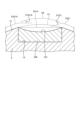
- Figure 4 is a cross-sectional view showing a schematic cross section taken along the center of the S-shaped groove surface.
- the imaginary line K1 shown in Figure 4 is a line extending in the circumferential direction from the outer circumferential raceway surface 13 of the screw shaft 2. Also, in Figure 4, only a portion of the multiple balls 4 is shown in order to make the S-shaped groove surface 21 easier to see.
- the central groove surface 30 and the bent groove surface 33 are positioned radially inward from the imaginary line K1. From the two bent groove surfaces 33 toward the center of the S-shaped direction of the central groove surface 30, they are gradually inclined to be positioned radially inward. In other words, the cross-sectional shape of the central groove surface 30 and the bent groove surface 33 cut along the S-shaped direction is concave. Therefore, the central groove surface 30 and the bent groove surface 33 are concave surfaces, and the ball 4 rolling on the central groove surface 30 and the bent groove surface 33 sinks radially inward.
- the ball 4 moves radially inward as it approaches the center of the S-shaped direction of the central groove surface 30 from one of the two bent groove surfaces 33 (see ball 4A among the balls 4 shown in Figure 4). Also, the ball 4A moves radially outward as it approaches the other bent groove surface 33 from the center of the S-shaped direction of the central groove surface 30. This causes the ball 4 to climb over the thread 6c of the inner circumferential raceway surface 6a.
- the radial movement amount when the ball 4 rolls on the S-shaped groove surface 21 (central groove surface 30 and bent groove surface 33) is R1.
- the height of the thread 6c on the inner circumferential raceway surface 6a is L1.
- the height of the thread 13a on the outer circumferential raceway surface 13 is L2.
- the height L2 of the thread 13a on the outer circumferential raceway surface 13 is greater than the height L1 of the thread 6c (L2>L1). Therefore, the ball 4 does not easily ride up onto the groove shoulder 13c on the outer circumferential raceway surface 13.
- the height is the distance (depth) from the groove bottom to the groove shoulder.
- the inlet/outlet groove surface 31 extends in the circumferential direction from the top-side opening 32.
- the groove bottom of the inlet/outlet groove surface 31 has a constant distance from the axis O1.
- the inlet/outlet groove surface 31 of this embodiment is not inclined so as to be positioned radially inward as it approaches the center of the S-shape. For this reason, the ball 4 rolling on the inlet/outlet groove surface 31 does not move radially inward even when it approaches the center of the S-shape of the central groove surface 30 (see ball 4B among the balls 4 shown in FIG. 4).
- the groove bottom of the inlet/outlet groove surface 31 is located radially inward from the imaginary line K1. Therefore, when a radially outward load acts on the top 5, the top 5 moves slightly radially outward.
- the ball 4B rolling on the inlet/outlet groove surface 31 also moves slightly radially outward and comes into contact with the inner circumferential raceway surface 6a of the nut 3. Therefore, the amount of radially outward movement of the top 5 is restricted to a small amount, and the top 5 does not come out of the recess 14.
- Figure 5 is a view of the opening (screw shaft side opening) of the outer peripheral raceway surface provided on the second opposing surface of the recess, viewed from the recess.
- the second opposing surface 16 of the inner peripheral surface 14b of the recess 14 is provided with a screw shaft side opening 13b of the outer peripheral raceway surface 13.
- This screw shaft side opening 13b is adjacent to the top side opening 32 of the top 5 (see Figures 2 to 4) in the rolling direction of the ball 4 (S-shaped direction).
- the groove shape of the inlet/outlet groove surface 31 of the S-shaped groove surface 21 is larger than the groove shape of the outer peripheral raceway surface 13.
- the groove shape of the top side opening 32 is also larger than the groove shape of the screw shaft side opening 13b.
- the screw shaft side opening 13b is positioned inside the top side opening 32. Therefore, the top side opening 32 is deeper and has a larger groove width than the screw shaft side opening 13b.
- the inlet/outlet groove surface 31 is positioned radially inward from the imaginary line K1 (the outer peripheral raceway surface 13).
- the load from the nut 3 acting on the inlet/outlet groove surface 31 via the balls 4 is reduced, and deformation of the top 5 is suppressed.
- Figure 6 shows the state in which the top has moved radially outward from the state in Figure 5.
- the groove shape of the top-side opening 32 is larger than the groove shape of the screw shaft-side opening 13b, so even if the top 5 is displaced radially outward, the top-side opening 32 does not move inward of the screw shaft-side opening 13b. In other words, it is possible to prevent the ball 4 moving from the outer peripheral raceway surface 13 to the inlet/outlet groove surface 31 from getting caught on the edge of the top-side opening 32.
- the top 5 has an outer diameter surface 20 facing radially outward.
- the outer diameter surface 20 is disposed radially outward from the groove shoulder 13c of the outer circumferential raceway surface 13.
- the tang 40 has a semi-cylindrical base portion 41 that protrudes radially outward from the outer diameter surface 20, and a tang body 42 that protrudes from the base portion 41 toward the top side opening 32.
- the two tangs 40 are spaced apart from each other in the axial direction.
- the thread 6c of the nut 3 is disposed between the two tangs 40.
- the tang 40 extends in the spiral direction. Although not specifically shown, the tang 40 is housed inside the inner circumferential raceway surface 6a of the nut 3. The tang 40 is also spaced apart from the inner circumferential raceway surface 6a of the nut 3 so as not to come into contact with it.
- the center of the tongue body 42 in the width direction (orthogonal direction) overlaps with the imaginary line Z.
- the length H2 of the tongue body 42 in the width direction (orthogonal direction) becomes smaller as it approaches the frame side opening 32, forming a tapered shape.
- the tip 43 of the tongue body 42 is disposed radially outward from the entrance/exit groove surface 31 (more specifically, disposed radially outward from the portion of the entrance/exit groove surface 31 closer to the bent groove surface 33).
- the center of the tongue body 42 in the spiral direction is disposed radially outward from the bent groove surface 33.
- the base 44 of the tongue body 42 is disposed radially outward from the central groove surface 30 (more specifically, disposed radially outward from the portion of the central groove surface 30 closer to the bent groove surface 33).
- the tip 43 of the tongue body 42 is positioned radially outward from the groove shoulder 6e of the inner raceway surface 6a. Therefore, the step amount L3 between the groove bottom of the inner raceway surface 6a and the tip 43 is small.
- the tongue body 42 has an inner diameter surface 45 that faces radially inward. The inner diameter surface 45 is inclined so as to be positioned radially inward as it approaches the base 44 from the tip 43.
- the ball 4 that enters the S-shaped groove surface 21 from the top side opening 32 comes into contact with the tip 43 of the tongue body 42 at the entrance/exit groove surface 31.
- the ball 4 which was moving in a spiral direction, changes direction toward the radially inward side (see arrow A1 in Figure 4).
- the ball 4 then moves along the radially inner side of the tongue body 42. Therefore, the path of the ball 4 is toward the radially inward side compared to when there is no tongue 40.
- the step amount L3 of the tip 43 is small, the ball 4 moves smoothly without getting caught when it comes into contact with the tip 43.
- the ball 4 moving radially inward of the tongue body 42 is guided by the inner diameter surface 45 so that it gradually moves radially inward. Therefore, the ball 4 moves along the concave surface (the central groove surface 30 and the bent groove surface 33). This reliably avoids contact between the ball 4 and the thread 6c of the inner circumferential raceway surface 6a.
- the effects of the ball screw device 1 of the embodiment will be described.
- the effects of the ball screw device 1 include a first effect, a second effect, and a third effect.
- the second and third effects will be described using comparative examples.
- the first effect is exerted when the ball 4 changes course on the S-shaped groove surface 21.
- an example will be given in which the ball 4 enters the top side opening 32 from the screw shaft side opening 13b located at the bottom left of Figure 3.
- FIG. 7 is an enlarged view of the recess and the part of the frame located at the lower left in FIG. 3.
- FIG. 8 is a cross-sectional view taken along line VIII-VIII in FIG. 7.
- the ball 4 that enters the S-shaped groove surface 21 from the frame side opening 32 moves in a spiral direction (imaginary line Z) along the entrance/exit groove surface 31.
- the ball 4 starts to bend from the imaginary line Z in the second direction X2 at the bent groove surface 33 (see W1 of the imaginary lines W in FIG. 7).
- the ball 4 moves in a direction inclined by ⁇ 1 degrees in the second direction X2 with respect to the spiral direction at the central groove surface 30.
- the portion of the S-shaped groove surface 21 that presses the ball 4 in the second direction X2 is the one-side groove surface (hereinafter referred to as the "guide surface 28") that is positioned in the first direction X1 from the imaginary line W.
- the amount of recession radially inward is small at both ends in the S-shape of the bent groove surface 33 and the central groove surface 30 (see FIG. 4). If there were no tang 40, part of the ball 4D would be positioned inside the inner raceway surface 6a of the nut 3 and would come into contact with the inner raceway surface 6a, as in the case of ball 4D shown in FIG. 8. The part of the inner raceway surface 6a that is in contact with the ball 4D becomes a one-side groove surface (hereinafter referred to as the opposing surface 6d) that is located in the second direction X2 from the center of the groove width of the inner raceway surface 6a.
- the opposing surface 6d one-side groove surface
- the ball 4E comes into contact with the tip 43 of the tongue body 42, and the course of the ball 4E is radially inward. Therefore, the ball 4E does not come into contact with the opposing surface 6d (opposing side abutment portion 6f), and the ball 4E is prevented from being pinched between the guide side abutment portion 29 and the opposing side abutment portion 6f. From the above, according to this embodiment, the first effect is achieved in that the smooth rolling of the ball 4 is ensured and damage to the groove shoulder 31b is avoided.
- the second effect is due to the fact that the top 5 is provided on the screw shaft 2. Therefore, in Comparative Example 1, the top 5 is provided on the nut 3.
- FIG. 9 is a cross-sectional view of the ball screw device of Comparative Example 1 cut along the center of the groove width of the S-shaped groove surface.
- the ball screw device 1001 of Comparative Example 1 includes a screw shaft 1002 and a nut 1003. This ball screw device 1001 differs from the embodiment in that a top 1005 is provided on the nut 1003.
- the height L11 of the thread 1006c on the inner circumferential raceway surface 1006a of the nut 1003 is L1, the same as in the embodiment.
- the height L12 of the thread 1013a on the outer circumferential raceway surface 1013 of the screw shaft 1002 is L2, the same as in the embodiment.
- the imaginary line K2 in FIG. 9 is a line extending the inner circumferential raceway surface 1006a in the circumferential direction.
- the radial movement amount of the ball 1004 is R2.
- This radial movement amount R2 is an amount of movement that exceeds the height amount L12 of the thread 1013a of the outer peripheral raceway surface 1013, in order to avoid contact with the thread 1013a.
- the thread 1006c has a small height amount of L11. Therefore, the bottom of the inner peripheral raceway surface 1006a is shallow, and the step amount between the bottom of the inner peripheral raceway surface 1006a and the deepest part of the S-groove surface 1021 is large. In other words, according to Comparative Example 1, the radial movement amount R2 of the ball 1004 is large.
- the thread 13a has a large height L2. Therefore, the bottom of the outer peripheral raceway surface 13 is deep, and the step between the bottom of the outer peripheral raceway surface 13 and the deepest part of the S-groove surface 21 is small.
- the radial movement amount R1 of the ball 4 is smaller than the movement amount R2 of Comparative Example 1.
- the step amount (radial movement amount) of the S-shaped groove surface 1021 of Comparative Example 1 is large.
- the step amount of the S-shaped groove surface 21 of the embodiment is small. Therefore, according to the embodiment, the inclination in the depth direction (radial direction) of the S-shaped groove surface 21 is gentle, and flatness is ensured. In other words, the embodiment achieves a second effect that the ball 4 rolling on the S-shaped groove surface 21 moves smoothly.
- the third effect is due to the fact that the length of the piece 5 (recess 14) in the cross direction Y is greater than its length in the axial direction. Therefore, in Comparative Example 2, a circular piece whose length in the cross direction Y and the axial direction are equal is presented.
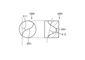
- FIG. 10 is a diagram showing an abstract of a top of Comparative Example 2.
- FIG. 11 is a diagram showing an abstract of a top of an embodiment.
- top 2005 of Comparative Example 2 has a circular outer shape.
- the angle at which the ball bends in the axial direction along S-shaped groove surface 2021 is ⁇ 11, which is relatively large.
- the angle at which the ball bends in the radial direction along S-shaped groove surface 2021 is ⁇ 12, which is relatively large.
- the piece 5 of the embodiment is longer in the transverse direction than in the axial direction. Therefore, the angle ⁇ 13 at which the ball bends in the axial direction along the S-shaped groove surface 21 is small, and the inclination is gentler than in Comparative Example 2. In addition, the angle ⁇ 14 at which the ball bends in the radial direction along the S-shaped groove surface 21 is also small, and the inclination is gentler than in Comparative Example 2. Therefore, according to the embodiment, a third effect is achieved in which the ball 4 rolls more smoothly along the S-shaped groove surface 21.
- the recess 14 and top 5 of the embodiment are parallelograms (rectangles) when viewed from the radial outside.
- the recess 14 and top 5 are non-circular. Therefore, simply by inserting the top 5 into the recess 14, the S-shaped groove surface 21 and the outer circumferential raceway surface 13 become continuous. Therefore, there is no need to rotate the top 5 to set the orientation of the top 5 after assembling the top 5 in the recess 14.
- the ball screw device 1 of the embodiment comprises a nut 3 having an inner circumferential raceway surface 6a on its inner circumferential surface, a screw shaft 2 inserted into the nut 3 and having an outer circumferential raceway surface 13 on its outer circumferential surface, a plurality of balls 4 arranged in a raceway 8 between the outer circumferential raceway surface 13 and the inner circumferential raceway surface 6a, and at least one or more tops 5 for circulating the balls 4.
- the outer circumferential surface of the screw shaft 2 is provided with at least one recess 14 that is recessed radially inward and accommodates the tops 5.
- the inner circumferential surface 14b of the recess 14 has two screw shaft side openings 13b of the outer circumferential raceway surface 13 that open towards the tops 5.
- the top 5 has a pair of top-side openings 32, 32 that open from the outer circumferential surface 24 of the top 5 and connect to the screw shaft side opening 13b, a circulation groove surface (S-shaped groove surface 21) that connects to each of the pair of top-side openings 32, 32 and whose internal space forms a circulation path, and a pair of tangs 40, 40 that are arranged radially outward from the circulation groove surface (S-shaped groove surface 21) and protrude toward the top-side opening 32.
- the tip 43 of the tang 40 is arranged radially outward from the imaginary spiral E (see FIG. 4) that connects the centers of the multiple balls 4 that roll on the raceway 8.
- the ball screw device 1 described above prevents the balls 4 from being pinched between the circulation groove surface (S-shaped groove surface 21) and the inner raceway surface 6a. This allows the balls 4 to roll smoothly and prevents damage to the top 5.
- the tang 40 of this embodiment also has an inner diameter surface 45 that faces radially inward.
- the inner diameter surface 45 is gradually inclined so as to be positioned radially inward as it moves away from the tip portion 43.
- the tip portion 43 in this embodiment is disposed on the inner circumferential raceway surface 6a of the nut 3.
- the circulation groove surface in this embodiment is an S-shaped groove surface 21.
- the S-shaped groove surface 21 is disposed near the top side opening 32 and has a spiral region that extends along the spiral direction in which the track 8 extends, and a bent region that is adjacent to the spiral region and gradually begins to deviate from the spiral direction.
- the tip portion 43 is disposed radially outward from the spiral region.
- the circulation groove surface in this embodiment is an S-shaped groove surface 21 formed in an S-shape.
- the length of the recess 14 and the piece 5 in the cross direction Y that intersects with the axial direction is longer than the length in the axial direction parallel to the screw shaft 2.
- the height L2 of the thread 13a on the outer peripheral raceway surface 13 is greater than the height L1 of the thread 6c on the inner peripheral raceway surface 6a.
- the balls 4 are less likely to ride up onto the groove shoulder 13c of the outer circumferential raceway surface 13.
- the radial inclination of the S-shaped groove surface 21 is gentler, allowing the balls 4 to move smoothly on the S-shaped groove surface 21.
- the circulation groove surface (S-shaped groove surface 21) of the embodiment has a pair of inlet/outlet groove surfaces 31, 31 arranged at both ends in the extension direction of the circulation groove surface (S-shaped groove surface 21) and extending circumferentially from the top side opening 32, and a concave surface (central groove surface 30 and bent groove surface 33) arranged between the pair of inlet/outlet groove surfaces 31, 31, into which the ball 4 sinks radially inward.
- the outer peripheral surface 24 of the top 5 is provided with a top-side opening 32 of the S-shaped groove surface 21.
- the inner peripheral surface 14b of the recess 14 is provided with a screw shaft side opening 13b of the outer peripheral raceway surface 13 that is continuous with the top-side opening 32.
- the groove shape of the top-side opening 32 is larger than the groove shape of the screw shaft side opening 13b.
- the present disclosure is not limited to the ball screw device exemplified in the embodiment.
- the ball screw device of the present disclosure may be applied to devices other than the electric actuator 104 and the brake caliper 100.
- the inner peripheral surface 14b of the recess 14 and the outer peripheral surface 24 of the frame 5 are parallelograms, but the present disclosure may be of a shape other than a parallelogram. Therefore, the inner peripheral surface 14b of the recess 14 and the outer peripheral surface 24 of the frame 5 may be, for example, a rectangular shape or an elliptical shape.
- the pair of first opposing surfaces 15, 15 and the pair of first side surfaces 25, 25 extend in the spiral direction, but may extend in the intersecting direction Y.
- the second opposing surface 16 and the second side surface 26 extend in a direction perpendicular to the spiral direction (see the imaginary line Z), but may extend in the axial direction.
- the shape when the recess 14 and the frame 5 are quadrangular, the shape includes a rectangle, a square, a parallelogram, a rhombus, a trapezoid, etc.
- the corners of the quadrangular shape may be R-shaped, and are not particularly limited.
- FIG. 12 is a schematic diagram of a frame of modified example 1 viewed from the radial outside.
- the circulation groove surface 221 may extend in a reverse spiral direction Z1 in the opposite direction to the spiral direction Z, as in frame 205 of modified example 1 shown in Figure 12.
- the inlet/outlet groove surface 231 of the circulation groove surface 221 also extends in the reverse spiral direction Z1.
- the S-shaped groove surface 21 has a straight central groove surface 30 and an inlet/outlet groove surface 31, but may have a curved portion.
- the center of the groove width of the top side opening 32 (see the imaginary line W in FIG. 3) and the center of the groove width of the outer peripheral track surface 13 are arranged to coincide with the spiral direction, but in the present disclosure, the center of the groove width of the top side opening 32 and the center of the groove width of the outer peripheral track surface 13 may not coincide with the spiral direction (they may be offset in the axial direction).
- the inlet/outlet groove surface 31 extends in the spiral direction, but the inlet/outlet groove surface of the present disclosure does not have to extend in the spiral direction. In other words, the inlet/outlet groove surface may extend in the cross direction Y or in the reverse spiral direction Z1 (see the inlet/outlet groove surface 231 in FIG. 12).
- FIG. 13 is a schematic diagram of a cross section of a piece of modified example 2 cut along the circulation groove surface.
- the circulation groove surface 321 may have only a concave surface in which the ball 4 sinks radially inward.
- the concave surface in this disclosure includes a concave surface 321A (see the imaginary line in FIG. 13) that is flat (linear) when viewed from the axial direction, in addition to the concave surface recessed toward the axis O1 as shown in the modified example 2. Even this flat concave surface 321A is positioned radially inward from the imaginary line K1 (extension of the outer peripheral raceway surface 13). In other words, the ball 4 can ride over the thread 6c (see FIG. 4) of the nut 3.
- the imaginary line K321 shown in FIG. 13 is the trajectory of the center of the ball 4 rolling on the outer peripheral raceway surface 13 and the circulation groove surface 321.
- the imaginary line K8 shown in FIG. 13 is an extension of the trajectory of the center of the ball 4 rolling on the outer peripheral raceway surface 13 (raceway 8).
- the bend angle ⁇ 321A when entering the concave surface 321A from the outer circumferential track surface 13 is smaller than the bend angle ⁇ 321 when entering the circulation groove surface 321 from the outer circumferential track surface 13. Therefore, the concave surface 321A allows the ball 4 to roll (enter) smoothly.
- the height L1 of the thread 6c on the inner peripheral raceway surface 6a may be the same as or greater than the height L2 of the thread 13a on the outer peripheral raceway surface 13.
- the link 5 in the embodiment is longer in the transverse direction Y than in the axial direction, but in the present disclosure, the link 5 may be longer in the axial direction.
- the top may be manufactured from a resin material such as nylon 66 resin.
- the top may also be manufactured by metal powder injection molding.
- the top in this embodiment is formed from one part, it may be composed of two or more parts.
- the top is composed of two or more parts, there are no particular limitations on the dividing surface. It may be divided into two, an inner circumference side and an outer circumference side, or it may be divided into two, a first direction X1 and a second direction X2.
- the tip 43 in the embodiment is disposed within the inner circumferential raceway surface 6a of the nut 3, but the present disclosure is not limited to this as long as it can guide the ball 4 radially inward.
- the tip 43 is disposed radially outward of the imaginary spiral E (see FIG. 4) that connects the centers D of the balls 4 rolling on the raceway 8. If disposed radially outward of the imaginary spiral E, the tip 43 will come into contact radially outward of the centers D of the balls 4. This is because the course of the balls 4 can be changed radially inward.
- the distance Q (see FIG. 12) between the tongue bodies 42 may be smaller than the diameter of the ball 4. This prevents the ball 4 from falling (getting caught) in the gap between the tongue bodies 42. In other words, the ball 4 moves smoothly from the inner diameter surface 45 of one tongue body 42 along the inner diameter surface 45 of the other tongue body 42.
- the tip 43 in this embodiment is disposed radially outward of the spiral region (entrance/exit groove surface 31), but the present disclosure is not limited to this.
- the position at which the ball 4 is pinched in the S-shaped groove surface 21 is not constant. Therefore, the tip 43 in this disclosure only needs to be disposed closer to the top side opening 32 than the predetermined position at which the ball 4 is pinched in the S-shaped groove surface 21.
- the present disclosure is not particularly limited, and the tip 43 of the tongue 40 may be disposed radially outward of the bent region (bent groove surface 33) or at the end of the S-shaped direction of the central groove surface 30. Modified examples are described below.
- FIG. 14 is a schematic diagram of a cross section of the top of the third modification cut along the circulation groove surface.
- the top 405 of the third modification has a pair of tangs 440.
- the tip 443 of the tongue body 442 of the tongue 440 is in contact with the imaginary line N1.
- This imaginary line N1 is a straight line passing through the axis O1 of the screw shaft 2 and the groove bottom 432N of the top side opening 432.
- the tip 443 does not exceed the imaginary line N1.
- FIG. 15 is a schematic diagram of a cross section of a top of modified example 4 cut along the circulation groove surface.
- Top 505 of modified example 4 has a pair of tongues 540.
- Tip 543 of tongue body 542 of tongue 540 is in contact with imaginary line N2.
- This imaginary line N2 extends in a straight line along second side surface 526 of top 505.
- tip 543 is positioned closer to top side opening 532 than in the embodiment. This reduces the possibility of ball 4 becoming trapped.
- FIG. 16 is a schematic diagram of the top of the fifth modification viewed from the radial outside.
- the top 605 of the fifth modification has a pair of tongues 640 (only one is shown).
- the top 605 has a circumferential (helical) length N3 from the axis O1 to the second side surface 626.
- the imaginary line N4 shown in FIG. 16 extends linearly in the axial direction and is disposed at a position where the distance from the axis O1 in the circumferential (helical) direction is half of N3.
- the tip 643 of the tongue body 642 is in contact with the imaginary line N3 when viewed from the radial outside.
- the tip 643 of the fifth modification is farther away from the top side opening 632 than the tip 443 of the third modification and the tip 543 of the fourth modification, but the present disclosure may be such a tongue 640.
- the tip of the tongue may be disposed between imaginary line N1 (see FIG. 14) and imaginary line N2 (see FIG. 15), or between imaginary line N2 (see FIG. 15) and imaginary line N4 (see FIG. 16). Even with such a tongue, smooth rolling of the balls can be ensured, and damage to the groove shoulder of the circulation groove surface can be avoided.
- FIG 17 is a schematic diagram of a block of modified example 6 viewed from the radial outside. More specifically, as shown in Figure 17, the present disclosure may be a block 705 having a wall portion 750 that connects the pair of tangs 740, 740 to each other. With this block 705 of modified example 6, it is possible to prevent the ball 4 from falling (moving radially outward) between the pair of tangs 740, 740. Therefore, it is possible to prevent the ball 4 from contacting the groove shoulder 6e of the nut 3 (see Figure 8).
- the inner peripheral side surface 733a arranged on the inner peripheral side may be arc-shaped (R-shaped) when viewed from the radially outside. This makes it difficult for the ball 4 to get caught on the inner peripheral side surface 733a, ensuring smooth rolling of the ball 4.
- the frame is: A pair of top-side openings that open from the outer peripheral surface of the top and connect to the screw shaft-side opening; a circulation groove surface connected to each of the pair of frame side openings and having an internal space that constitutes a circulation path; A pair of tongues are disposed radially outward of the circulation groove surface and protrude toward the top
- the tang has an inner diameter surface facing radially inward,
- the ball screw device according to (1) wherein the inner diameter surface is inclined so as to be positioned gradually radially inward as it moves away from the tip end portion.
- the circulation groove surface is an S-shaped groove surface formed in an S-shape,
- the S-groove surface is a spiral region disposed near the top opening and extending along the spiral direction in which the track extends; a bend region adjacent to the helical region and gradually deviating from the helical direction; having The ball screw device according to any one of (1) to (3), wherein the tip portion is disposed radially outward from the helical region.
- the circulation groove surface is an S-shaped groove surface formed in an S-shape,
- the S-groove surface is a spiral region disposed near the top opening and extending along the spiral direction in which the track extends; a bend region adjacent to the helical region and gradually deviating from the helical direction; having The ball screw device according to any one of (1) to (3), wherein the tip portion is disposed radially outward from the bending region.
- the circulation groove surface is an S-shaped groove surface formed in an S-shape, When viewed from the radial outside of the screw shaft, the recess and the top have a length in a direction intersecting the axial direction that is longer than the length in an axial direction that is parallel to the screw shaft.
- the circulation groove surface is A pair of inlet/outlet groove surfaces are disposed at both ends of the extension direction of the circulation groove surface and extend in a circumferential direction from the frame side opening; a concave surface disposed between the pair of inlet/outlet groove surfaces and into which the ball sinks radially inward;
- (11) The ball screw device according to any one of (1) to (10), wherein the groove shape of the top side opening is larger than the groove shape of the screw shaft side opening.
Landscapes
- Engineering & Computer Science (AREA)
- General Engineering & Computer Science (AREA)
- Mechanical Engineering (AREA)
- Transmission Devices (AREA)
- Braking Arrangements (AREA)
Abstract
Description
(1)
内周面に内周軌道面が設けられたナットと、
前記ナットに挿入され、外周面に外周軌道面が設けられたねじ軸と、
前記外周軌道面と前記内周軌道面との間の軌道に配置された複数のボールと、
前記ボールを循環させる少なくとも1つ以上のコマと、
を備え、
前記ねじ軸の外周面には、径方向内側に窪み、前記コマを収容する凹部が少なくとも1つ以上設けられ、
前記凹部の内周面には、前記コマに向かって開口する前記外周軌道面のねじ軸側開口が2つ設けられ、
前記コマは、
前記コマの外周面から開口し、前記ねじ軸側開口と接続する一対のコマ側開口と、
一対の前記コマ側開口のそれぞれと接続し、内部空間が循環路を構成する循環用溝面と、
前記循環用溝面の径方向外側に配置され、かつ前記コマ側開口に向かって突出する一対のタングと、
を有し、
前記タングの先端部は、前記軌道を転動する複数のボールの中心同士を結ぶ仮想螺旋よりも径方向外側に配置されている
ボールねじ装置。
(2)
前記タングは、径方向内側を向く内径面を有し、
前記内径面は、前記先端部から離れるにつれて、次第に径方向内側に位置するように傾斜している
(1)に記載のボールねじ装置。
(3)
前記先端部は、前記ナットの前記内周軌道面に配置されている
(1)又は(2)に記載のボールねじ装置。
(4)
前記循環用溝面は、S字状に形成されたS字溝面であり、
前記S字溝面は、
前記コマ側開口の近傍に配置され、前記軌道が延在する螺旋方向に沿って延在する螺旋領域と、
前記螺旋領域に隣接し、前記螺旋方向から次第に外れ始める屈曲領域と、
を有し、
前記先端部は、前記螺旋領域に対し径方向外側に配置されている
(1)から(3)のいずれか1つに記載のボールねじ装置。
(5)
前記循環用溝面は、S字状に形成されたS字溝面であり、
前記S字溝面は、
前記コマ側開口の近傍に配置され、前記軌道が延在する螺旋方向に沿って延在する螺旋領域と、
前記螺旋領域に隣接し、前記螺旋方向から次第に外れ始める屈曲領域と、
を有し、
前記先端部は、前記屈曲領域に対し径方向外側に配置されている
(1)から(3)のいずれか1つに記載のボールねじ装置。
(6)
前記循環用溝面は、S字状に形成されたS字溝面であり、
前記ねじ軸の径方向外側から視て、前記凹部及び前記コマは、前記ねじ軸と平行な軸方向の長さよりも、前記軸方向に交差する交差方向の長さの方が長い
(1)から(5)のいずれか1つに記載のボールねじ装置。
(7)
前記循環用溝面は、前記軌道が延在する螺旋方向と逆回りの逆螺旋方向に延在している
(1)から(3)のいずれか1つに記載のボールねじ装置。
(8)
前記外周軌道面におけるねじ山の高さ量は、前記内周軌道面におけるねじ山の高さ量よりも大きい
(1)から(7)のいずれか1つに記載のボールねじ装置。
(9)
前記循環用溝面は、
前記循環用溝面が延在する延在方向の両端部に配置され、前記コマ側開口から周方向に延在する一対の出入口溝面と、
一対の前記出入口溝面の間に配置され、径方向内側に前記ボールが沈む凹面と、
を有している
(1)から(8)のいずれか1つに記載のボールねじ装置。
(10)
前記循環用溝面は、径方向内側に前記ボールが沈む凹面を有し、
前記凹面は、軸方向から視て直線状となっている
(1)から(8)のいずれか1つに記載のボールねじ装置。
(11)
前記コマ側開口の溝形は、前記ねじ軸側開口の溝形よりも大きい
(1)から(10)のいずれか1つに記載のボールねじ装置。
2、1002 ねじ軸
3、1003 ナット
4、1004 ボール
5、205、305、405、505、605、705、1005、2005 コマ
6 ナット本体
6a、1006a 内周軌道面
6c、1006c ねじ山
6e 溝肩
6f 対向側当接部
8 軌道
11 ねじ軸本体
13 外周軌道面
13a ねじ山
13b ねじ軸側開口
13c 溝肩
14 凹部
15 第1対向面
16 第2対向面
18 肉薄部
20 外径面
21、1021、2021 S字溝面(循環用溝面)
25 第1側面
26 第2側面
29 案内側当接部
30 中央溝面
31 出入口溝面
32 コマ側開口
33 屈曲溝面
40 タング
100 ブレーキキャリパー
104 電動アクチュエータ
120 ハウジング
Claims (11)
- 内周面に内周軌道面が設けられたナットと、
前記ナットに挿入され、外周面に外周軌道面が設けられたねじ軸と、
前記外周軌道面と前記内周軌道面との間の軌道に配置された複数のボールと、
前記ボールを循環させる少なくとも1つ以上のコマと、
を備え、
前記ねじ軸の外周面には、径方向内側に窪み、前記コマを収容する凹部が少なくとも1つ以上設けられ、
前記凹部の内周面には、前記コマに向かって開口する前記外周軌道面のねじ軸側開口が2つ設けられ、
前記コマは、
前記コマの外周面から開口し、前記ねじ軸側開口と接続する一対のコマ側開口と、
一対の前記コマ側開口のそれぞれと接続し、内部空間が循環路を構成する循環用溝面と、
前記循環用溝面の径方向外側に配置され、かつ前記コマ側開口に向かって突出する一対のタングと、
を有し、
前記タングの先端部は、前記軌道を転動する複数のボールの中心同士を結ぶ仮想螺旋よりも径方向外側に配置されている
ボールねじ装置。 - 前記タングは、径方向内側を向く内径面を有し、
前記内径面は、前記先端部から離れるにつれて、次第に径方向内側に位置するように傾斜している
請求項1に記載のボールねじ装置。 - 前記先端部は、前記ナットの前記内周軌道面に配置されている
請求項1又は請求項2に記載のボールねじ装置。 - 前記循環用溝面は、S字状に形成されたS字溝面であり、
前記S字溝面は、
前記コマ側開口の近傍に配置され、前記軌道が延在する螺旋方向に沿って延在する螺旋領域と、
前記螺旋領域に隣接し、前記螺旋方向から次第に外れ始める屈曲領域と、
を有し、
前記先端部は、前記螺旋領域に対し径方向外側に配置されている
請求項1から請求項3のいずれか1項に記載のボールねじ装置。 - 前記循環用溝面は、S字状に形成されたS字溝面であり、
前記S字溝面は、
前記コマ側開口の近傍に配置され、前記軌道が延在する螺旋方向に沿って延在する螺旋領域と、
前記螺旋領域に隣接し、前記螺旋方向から次第に外れ始める屈曲領域と、
を有し、
前記先端部は、前記屈曲領域に対し径方向外側に配置されている
請求項1から請求項3のいずれか1項に記載のボールねじ装置。 - 前記循環用溝面は、S字状に形成されたS字溝面であり、
前記ねじ軸の径方向外側から視て、前記凹部及び前記コマは、前記ねじ軸と平行な軸方向の長さよりも、前記軸方向に交差する交差方向の長さの方が長い
請求項1から請求項5のいずれか1項に記載のボールねじ装置。 - 前記循環用溝面は、前記軌道が延在する螺旋方向と逆回りの逆螺旋方向に延在している
請求項1から請求項3のいずれか1項に記載のボールねじ装置。 - 前記外周軌道面におけるねじ山の高さ量は、前記内周軌道面におけるねじ山の高さ量よりも大きい
請求項1から請求項7のいずれか1項に記載のボールねじ装置。 - 前記循環用溝面は、
前記循環用溝面が延在する延在方向の両端部に配置され、前記コマ側開口から周方向に延在する一対の出入口溝面と、
一対の前記出入口溝面の間に配置され、径方向内側に前記ボールが沈む凹面と、
を有している
請求項1から請求項8のいずれか1項に記載のボールねじ装置。 - 前記循環用溝面は、径方向内側に前記ボールが沈む凹面を有し、
前記凹面は、軸方向から視て直線状となっている
請求項1から請求項8のいずれか1項に記載のボールねじ装置。 - 前記コマ側開口の溝形は、前記ねじ軸側開口の溝形よりも大きい
請求項1から請求項10のいずれか1項に記載のボールねじ装置。
Priority Applications (3)
| Application Number | Priority Date | Filing Date | Title |
|---|---|---|---|
| CN202480025681.9A CN121079522A (zh) | 2023-05-09 | 2024-04-05 | 滚珠丝杠装置 |
| DE112024000978.6T DE112024000978T5 (de) | 2023-05-09 | 2024-04-05 | Kugelgewindetrieb |
| JP2024541225A JP7586382B1 (ja) | 2023-05-09 | 2024-04-05 | ボールねじ装置 |
Applications Claiming Priority (2)
| Application Number | Priority Date | Filing Date | Title |
|---|---|---|---|
| JP2023077324 | 2023-05-09 | ||
| JP2023-077324 | 2023-05-09 |
Publications (1)
| Publication Number | Publication Date |
|---|---|
| WO2024232201A1 true WO2024232201A1 (ja) | 2024-11-14 |
Family
ID=93430015
Family Applications (1)
| Application Number | Title | Priority Date | Filing Date |
|---|---|---|---|
| PCT/JP2024/014081 Ceased WO2024232201A1 (ja) | 2023-05-09 | 2024-04-05 | ボールねじ装置 |
Country Status (4)
| Country | Link |
|---|---|
| JP (1) | JP7586382B1 (ja) |
| CN (1) | CN121079522A (ja) |
| DE (1) | DE112024000978T5 (ja) |
| WO (1) | WO2024232201A1 (ja) |
Citations (3)
| Publication number | Priority date | Publication date | Assignee | Title |
|---|---|---|---|---|
| JP2003166616A (ja) * | 2001-09-21 | 2003-06-13 | Koyo Seiko Co Ltd | ボールねじ装置 |
| JP2019190506A (ja) * | 2018-04-20 | 2019-10-31 | Thk株式会社 | ボールねじ装置 |
| US20200300343A1 (en) * | 2019-03-23 | 2020-09-24 | Claverham Limited | Linear actuators |
-
2024
- 2024-04-05 JP JP2024541225A patent/JP7586382B1/ja active Active
- 2024-04-05 WO PCT/JP2024/014081 patent/WO2024232201A1/ja not_active Ceased
- 2024-04-05 CN CN202480025681.9A patent/CN121079522A/zh active Pending
- 2024-04-05 DE DE112024000978.6T patent/DE112024000978T5/de active Pending
Patent Citations (3)
| Publication number | Priority date | Publication date | Assignee | Title |
|---|---|---|---|---|
| JP2003166616A (ja) * | 2001-09-21 | 2003-06-13 | Koyo Seiko Co Ltd | ボールねじ装置 |
| JP2019190506A (ja) * | 2018-04-20 | 2019-10-31 | Thk株式会社 | ボールねじ装置 |
| US20200300343A1 (en) * | 2019-03-23 | 2020-09-24 | Claverham Limited | Linear actuators |
Also Published As
| Publication number | Publication date |
|---|---|
| DE112024000978T5 (de) | 2025-12-11 |
| JPWO2024232201A1 (ja) | 2024-11-14 |
| JP7586382B1 (ja) | 2024-11-19 |
| CN121079522A (zh) | 2025-12-05 |
Similar Documents
| Publication | Publication Date | Title |
|---|---|---|
| JP7384327B1 (ja) | ボールねじ装置 | |
| CN101680483B (zh) | 滚动装置及其使用方法 | |
| JP2022091734A (ja) | 同軸歯車装置 | |
| CN111406167B (zh) | 滚珠丝杠花键 | |
| JP5341893B2 (ja) | ねじ装置 | |
| JP7586382B1 (ja) | ボールねじ装置 | |
| JP2023521792A5 (ja) | ||
| JP2024118705A (ja) | ボールねじ装置 | |
| JP2024147964A (ja) | ボールねじ装置 | |
| JP2002276765A (ja) | ダブルナット予圧式ボールねじ | |
| JP7091011B2 (ja) | 波動歯車装置の波動発生器 | |
| JP7601298B1 (ja) | ボールねじ装置 | |
| JP6805961B2 (ja) | ボールねじ装置及びアクチュエータ | |
| JPH08303455A (ja) | 円筒ころ軸受および保持器付ころ | |
| CN118369526A (zh) | 滚珠丝杠装置 | |
| JPS642973Y2 (ja) | ||
| JP7477062B1 (ja) | ナット及びボールねじ装置 | |
| JP7543998B2 (ja) | ボールねじ装置 | |
| JP7838401B2 (ja) | ボールねじ装置 | |
| JP7802439B2 (ja) | ボールねじ装置 | |
| CN100432492C (zh) | 滚柱丝杠 | |
| JP2024058020A (ja) | ボールねじ装置 | |
| US20250271050A1 (en) | Ball screw device | |
| JP2008157374A (ja) | ボールねじ機構 | |
| KR20010095209A (ko) | 로울링 안내 장치의 로울링 요소 스페이서 |
Legal Events
| Date | Code | Title | Description |
|---|---|---|---|
| WWE | Wipo information: entry into national phase |
Ref document number: 2024541225 Country of ref document: JP |
|
| 121 | Ep: the epo has been informed by wipo that ep was designated in this application |
Ref document number: 24803316 Country of ref document: EP Kind code of ref document: A1 |
|
| WWE | Wipo information: entry into national phase |
Ref document number: 112024000978 Country of ref document: DE |
|
| WWP | Wipo information: published in national office |
Ref document number: 112024000978 Country of ref document: DE |
|
| 122 | Ep: pct application non-entry in european phase |
Ref document number: 24803316 Country of ref document: EP Kind code of ref document: A1 |