WO2024232175A1 - 金型部品、成形用金型、成形物の成形方法 - Google Patents
金型部品、成形用金型、成形物の成形方法 Download PDFInfo
- Publication number
- WO2024232175A1 WO2024232175A1 PCT/JP2024/011815 JP2024011815W WO2024232175A1 WO 2024232175 A1 WO2024232175 A1 WO 2024232175A1 JP 2024011815 W JP2024011815 W JP 2024011815W WO 2024232175 A1 WO2024232175 A1 WO 2024232175A1
- Authority
- WO
- WIPO (PCT)
- Prior art keywords
- mold
- die
- molding
- molded product
- mold part
- Prior art date
- Legal status (The legal status is an assumption and is not a legal conclusion. Google has not performed a legal analysis and makes no representation as to the accuracy of the status listed.)
- Ceased
Links
Images



Classifications
-
- B—PERFORMING OPERATIONS; TRANSPORTING
- B29—WORKING OF PLASTICS; WORKING OF SUBSTANCES IN A PLASTIC STATE IN GENERAL
- B29C—SHAPING OR JOINING OF PLASTICS; SHAPING OF MATERIAL IN A PLASTIC STATE, NOT OTHERWISE PROVIDED FOR; AFTER-TREATMENT OF THE SHAPED PRODUCTS, e.g. REPAIRING
- B29C45/00—Injection moulding, i.e. forcing the required volume of moulding material through a nozzle into a closed mould; Apparatus therefor
- B29C45/17—Component parts, details or accessories; Auxiliary operations
- B29C45/26—Moulds
-
- B—PERFORMING OPERATIONS; TRANSPORTING
- B29—WORKING OF PLASTICS; WORKING OF SUBSTANCES IN A PLASTIC STATE IN GENERAL
- B29C—SHAPING OR JOINING OF PLASTICS; SHAPING OF MATERIAL IN A PLASTIC STATE, NOT OTHERWISE PROVIDED FOR; AFTER-TREATMENT OF THE SHAPED PRODUCTS, e.g. REPAIRING
- B29C45/00—Injection moulding, i.e. forcing the required volume of moulding material through a nozzle into a closed mould; Apparatus therefor
- B29C45/17—Component parts, details or accessories; Auxiliary operations
- B29C45/26—Moulds
- B29C45/27—Sprue channels ; Runner channels or runner nozzles
Definitions
- the present invention relates to mold parts, molding dies, and molding methods for molded products.
- molded objects such as plastic models made from resin are constructed by connecting multiple parts to be assembled to a runner (see Patent Document 1).
- the injection mold is composed of a fixed side and a movable side, and such molded products are produced when the molding material poured into the cavity formed between the fixed side and the movable side hardens.
- the shape and structure of the molded product produced depends on the shape of the injection mold.
- the objective of the present invention is to provide mold parts, molding dies, and molding methods for molded products that do not limit the shape or structure of the molded products that can be produced.
- the present invention relates, for example, to a mold part that is placed in a molding die consisting of a first die and a second die for injecting a molding material into an internal cavity to produce a molded product corresponding to the shape of the cavity, the mold part including a first mold part and a second mold part that are inserted and removed by sliding from a side surface of the molding die perpendicular to the contact surface between the first die and the second die, and the first mold part and the second mold part form a hollow portion that connects the first opening to the second opening of the molded product.
- Another aspect of the present invention is, for example, a molding die having the above-mentioned die parts, comprising a first die and a second die, and at least one of the first die and the second die has a runner groove formed so as to bypass the insertion and removal paths of the first die part and the second die part.
- a further aspect of the present invention is, for example, a method for molding a molded product, which includes a first step of injecting a molding material into the above-mentioned molding die in which the first mold part and the second mold part are arranged in predetermined positions to mold a molded product composed of multiple parts connected to a runner, a second step of removing the first mold part from the molding die, a third step of removing the second mold part from the molding die, and a fourth step of removing the molded product.
- the present invention can provide mold parts, molding dies, and molding methods for molded products that do not limit the shape or structure of the moldable products.
- FIG. 2 is a cross-sectional view illustrating the molding device 10 according to the embodiment.
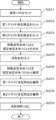
- 4 is a flowchart corresponding to an example of a molding method for a molded product according to the embodiment.
- FIG. 2 is a diagram showing an example of the appearance of a molded product according to the embodiment.
- 13A to 13C are diagrams showing examples of how slide mold parts are used to explain a molding method for a molded product.
- FIG. 4 is a diagram for explaining the correspondence between the surfaces constituting the molded product and the slide mold parts.
- FIG. 13 is a diagram showing an example of a runner configuration for ensuring an insertion/removal path for slide mold parts.
- thermoplastic resins such as polystyrene, polyethylene, and ABS, thermosetting resins, metals, etc.
- Figure 1 shows a cross-sectional view of a molding device 10 corresponding to an embodiment of the invention.
- the molding device 10 of this embodiment has a movable mold body 102 attached to the moving side of a molding material injection device (not shown) that injects molding material, and a fixed mold body 103 attached to the fixed side of the molding material injection device.
- the movable mold body 102 and the fixed mold body 103 each have a runner groove formed therein through which the molding material flows.
- the movable mold body 102 has a male mold mounting plate 107 to which a male mold 106 is attached, a fixed base 108 to which the male mold mounting plate 107 is fixed, a movable side mounting plate 109 to which the molding material injection device is attached, and a spacer 110 provided between the fixed base 108 and the movable side mounting plate 109.
- the male mold 106 and the male mold mounting plate 107 may be integrally configured, or may be configured separately and independently.
- a vacant chamber 111 is formed in the fixed base 108, and a movable push plate 112 is provided in the vacant chamber 111.
- the push plate 112 is fixed to a pressing shaft 116 provided in openings 114, 115 formed in the fixed base 108 and the movable side mounting plate 109.
- a knockout pin 113 that penetrates the male mold mounting plate 107 and the male mold 106 is formed in the push plate 112.
- the tip of the knock-out pin 113 is formed to protrude into the runner groove.
- the fixed mold body 103 has a fixed mounting plate 117 attached to the molding material injection device, a female mold mounting plate 119 to which a female mold 118 is attached, and a spacer 120 provided between the fixed mounting plate 117 and the female mold mounting plate 119.
- the female mold 118 and the female mold mounting plate 119 may be integrally configured, or may be configured as separate, independent bodies.
- a sprue bush 104 is attached to the fixed mold body 103 for injecting molten molding material from a molding injection device.
- the sprue bush 104 extends through the fixed mounting plate 117 to the female mold 118, and a sprue 105 is formed inside the sprue bush 104, which serves as a supply flow path for molten resin.
- the sprue 105 is connected to a runner groove formed in the female mold 118 and the male mold 106, and the molding material flows into the molding space (cavity) formed in the female mold 118 and the male mold 106 through this runner groove.
- the male mold 106 and the female mold 118 each have a concave-convex shape, and these concave-convex shapes combine to form a cavity that defines the outer shape of the molded product.
- the molding material flows into the cavity, and when it cools and hardens, a molded product corresponding to the cavity shape is formed.
- the male mold 106 and the female mold 118 are collectively referred to as the molding die.
- the molding die is configured to include multiple die parts that are configured to be insertable and removable from the molding die.
- the die parts are placed on the contact surface between the male die 106 and the female die 118, and are inserted into the cavity formed in the molding die from the side of the molding die that is perpendicular to the contact surface. This makes it possible to prevent the molding material from flowing into the inside of the cavity defined by the male die 106 and the female die 118, making it possible to form a hollow or cylindrical molded product.
- mold parts by inserting mold parts from multiple directions into a cavity for molding one molded product, it is possible to mold a molded product with a shape that would not be possible with a single mold part.
- the above-mentioned mold parts are called slide mold parts.
- molding material is poured into the runner grooves and the cavities for forming each part to form a molded product, and then the movable mold body 102 is separated from the fixed mold body 103, and then the slide mold parts are separated from the movable mold body 102.
- the pressing shaft 116 is pressed to move the push-out plate 112, and the knock-out pin 113 provided on the push-out plate 112 pushes out the molded product attached to the male mold 106 that constitutes the movable mold body 102, and the molded product can be removed.
- FIG 1 shows an example of the structure of the molding device 10, but the structure of the molding device 10 is not limited to that shown in Figure 1 and various modifications are possible.
- the male mold 106 is set on the movable mold body 102 of the molding device 10, and then in S202, the first slide mold part is set, and in S203, the second slide mold part is set.
- the first slide mold part and the second slide mold part are set as a pair of mold parts, and a hollow molded product can be molded by combining the two slide mold parts and the male mold 106 and female mold 118.
- multiple pairs of the slide mold parts can be included for the male mold 106 and female mold 118. Three or more slide mold parts may also be combined for one molded product.
- the first slide mold part and the second slide mold part can be attached to a specified slide mechanism of the movable mold body 102 of the molding device 10.
- the slide mechanism allows each slide mold to slide (slide) in a specified direction and be inserted into the cavity formed by the male and female molds before the molding material is added, and is removed after the molding material has solidified.
- next step S204 the movable mold body 102 including the slide mold parts is moved towards the fixed mold body 103 and combined with the fixed mold body 103.
- next step S205 molding material is injected from the sprue 105 and flows into the cavity formed by the male mold 106, female mold 118 and slide mold parts. After that, once the molding material has cooled and solidified, the movable mold body 102 is separated from the fixed mold body 103. At this point, the molded product is attached to the movable mold body 102 side.
- the first slide mold part is separated from the interior of the molded product by the slide mechanism of the molding device 10 described above, and in S208, the second slide mold part is separated from the interior of the molded product by the slide mechanism of the molding device 10 described above. Since the molded product may be damaged if an attempt is made to remove the molded product before the slide mold parts are separated, the molded product is removed after all slide mold parts have been separated.
- the pusher plate 112 is moved to protrude the tip of the knockout pin 113 into the runner groove, thereby removing the molded product.
- Figure 3 (A) is a diagram showing an example of the appearance of molded product 300 from a direction in which opening 301 of molded product 300 faces forward.
- Figure 3 (B) is a diagram showing an example of the appearance of molded product 300 from a direction in which opening 301 of molded product 300 faces left.
- Figure 3 (C) is a diagram showing an example of the appearance of molded product 300 from the bottom side of molded product 300.
- Molded object 300 shown in Figure 3 is a hollow model part that has two openings, opening 301 on the front and opening 303 on the bottom, and these openings are connected. Molded object 300 is configured so that it can be connected to other molded objects via openings 301 and 303, thereby forming part of a finished toy body. Openings 301 and 303 are formed on different sides of molded object 300, but the arrangement of the openings is not limited to the form shown in Figure 3.
- first slide mold part that is inserted from the opening 303 side to form a hollow portion
- second slide mold part that is used to form the edge portion 302 of the opening 301
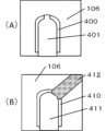
- Figure 4 is a cross-sectional view showing an example of the relationship between the slide mold parts and the male mold 106.
- (A) shows the case where only a single slide mold part 401 is used, and (B) shows the case where slide mold parts 411 and 412 are used.
- the slide mold part 401 is inserted from the bottom side of the male mold 106, with the top side protruding. This allows the molding of a hollow molded product 400. However, at this time, the opening on the top side of the molded product 400 must be shaped in such a way that it does not interfere with the removal of the slide mold part 401.
- the slide mold part 411 is inserted from the bottom side of the male mold 106, and the slide mold part 412 is inserted from the diagonally upward direction of the male mold 106 into the top side.
- This allows the molding of a hollow molded product 410.
- the slide mold part 411 and the slide mold part 412 are inserted and removed from different sides of the molding die.
- the shape of the opening on the top side of the molded product 410 is determined by the combination of the slide mold part 411 and the slide mold part 412.
- the first part of the opening that does not interfere with the withdrawal of the slide mold part 411 can be formed by the slide mold part 411, and the remaining second part can be formed within a range that does not interfere with the withdrawal of the slide mold part 412.
- the entire opening especially the edge part
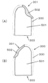
- Figure 5(A) shows an example of the cross-sectional configuration when molded product 300 is viewed from one direction at cross section A-A of molded product 300 in Figure 3(A).
- Figure 5(B) shows an example of the cross-sectional configuration when molded product 300 is viewed from the opposite direction at cross section A-A of molded product 300 in Figure 3(A).
- the area corresponding to the inner wall portion 501 continuing from the lower opening 303 of the molded product 300 can be molded by a first slide mold part corresponding to slide mold part 411 in Figure 4.
- the area corresponding to the portion shown as edge portion 302 of opening 301 of molded product 300 in Figure 3 can be molded by a second slide mold part corresponding to slide mold part 412 in Figure 4. In this way, by combining slide mold parts, it is possible to mold a molded product with a shape that could not be molded with a single slide mold part.
- Figure 6(A) is a diagram showing an example of a state in which a slide mold part has been inserted
- Figure 6(B) is a diagram showing an example of a state in which a slide mold part has been removed. Note that the male mold 106 and female mold 118 are omitted in Figure 6.
- the slide mold part 602 is inserted into the molded product 601.
- the molded product 601 is connected to the runner 603.
- the runner part 603 of the runner that exists in the insertion/removal direction of the slide mold part is shaped to bypass (or straddle) the slide mold part 602.
- the insertion/removal path of the slide mold part 602 is secured, so that the runner part 603 does not get in the way during insertion/removal.
- a runner groove is formed in at least one of the male mold 106 and the female mold 118 so as to bypass the slide mold part 602 or its insertion/removal path.
- Figure 6 shows a case where there is a runner part 603 in only one direction, but when using the two slide mold parts described above or more slide mold parts, the runners located in the insertion/removal direction of each slide mold part are arranged in a detour to ensure an insertion/removal path for the slide mold parts.
- the above embodiment discloses at least the following mold parts, molding dies, and molding methods for molded products.
- a molding mold comprising the mold part according to any one of (1) to (5), the molding mold comprising a first mold and a second mold, and having a runner groove formed in at least one of the first mold and the second mold so as to bypass the insertion and removal paths of the first mold part and the second mold part.
- a molding method for a molded product comprising: a first step of injecting a molding material into the molding die in which the first and second mold parts are arranged in predetermined positions to mold a molded product composed of a plurality of parts connected to a runner; a second step of removing the first mold part from the molding die; a third step of removing the second mold part from the molding die; and a fourth step of taking out the molded product.
Landscapes
- Engineering & Computer Science (AREA)
- Manufacturing & Machinery (AREA)
- Mechanical Engineering (AREA)
- Moulds For Moulding Plastics Or The Like (AREA)
- Injection Moulding Of Plastics Or The Like (AREA)
- Molds, Cores, And Manufacturing Methods Thereof (AREA)
Abstract
【課題】成形可能な成形物の形状や構造が限定されないような金型部品等を提供する。【解決手段】金型部品であって、成形材料を内部のキャビティに注入して、前記キャビティの形状に対応する成形物を生成するための第1の金型と第2の金型とからなる成形用金型に配置される金型部品であって、前記第1の金型と前記第2の金型との接触面に直交する前記成形用金型の側面より摺動により挿抜される第1の金型部品と、第2の金型部品とを含み、前記第1の金型部品と前記第2の金型部品とは、前記成形物の第1の開口から第2の開口に接続する中空部分を形成する。
Description
本発明は、金型部品、成形用金型、成形物の成形方法に関する。
一般に樹脂を用いて成形されたプラスチックモデルのような成形物は、ランナーに組み立ての対象となる複数のパーツが接続されて構成されている(特許文献1を参照)。
そのような成形物は、射出金型は固定側と可動側とで構成され、固定側と可動側との間に形成されたキャビティに流入された成形材料が固まることにより生成される。生成された成形物の形状や構造は射出金型の形態に依存する。
本発明では、成形可能な成形物の形状や構造が限定されないような金型部品、成形用金型、成形物の成形方法を提供することを目的とする。
本発明は、例えば、金型部品であって、成形材料を内部のキャビティに注入して、前記キャビティの形状に対応する成形物を生成するための第1の金型と第2の金型とからなる成形用金型に配置される金型部品であって、前記第1の金型と前記第2の金型との接触面に直交する前記成形用金型の側面より摺動により挿抜される第1の金型部品と、第2の金型部品とを含み、前記第1の金型部品と前記第2の金型部品とは、前記成形物の第1の開口から第2の開口に接続する中空部分を形成する。
本発明の他の一つは、例えば、上述の金型部品を備える成形用金型であって、第1の金型と、第2の金型とを備え、前記第1の金型及び前記第2の金型の少なくともいずれかに、前記第1の金型部品及び前記第2の金型部品の挿抜経路を迂回するように形成されたランナー溝を有する。
本発明の更に他の一つは、例えば成形物の成形方法であって、上述の成形用金型であって前記第1の金型部品と前記第2の金型部品が所定位置に配置された成形用金型に成形材料を注入して、複数のパーツがランナーに接続されて構成される成形物を成形する第1の工程と、前記成形用金型から、前記第1の金型部品を抜去する第2の工程と、前記成形用金型から、前記第2の金型部品を抜去する第3の工程と、前記成形物を取り出す第4の工程とを含む。
本発明では、成形可能な成形物の形状や構造が限定されないような金型部品、成形用金型、成形物の成形方法を提供することができる。
以下、添付図面を参照して実施形態を詳しく説明する。尚、以下の実施形態は特許請求の範囲に係る発明を限定するものではなく、また実施形態で説明されている特徴の組み合わせの全てが発明に必須のものとは限らない。実施形態で説明されている複数の特徴うち二つ以上の特徴が任意に組み合わされてもよい。また、同一若しくは同様の構成には同一の参照番号を付し、重複した説明は省略する。また、各図において、紙面に対する上下左右表裏方向を、本実施形態における部品(またはパーツ)の上下左右表裏方向として、本文中の説明の際に用いることとする。なお本発明は、以下に説明する実施形態おいて成形材料として樹脂材料を想定するがこれに限定されず、他の材質(ポリスチレン、ポリエチレン、ABS等の熱可塑性樹脂、熱硬化性樹脂、金属等)も適用可能である。
図1に発明の実施形態に対応する成形装置10の断面図を示す。本実施形態の成形装置10は図1に示すように、成形材料を射出する不図示の成形材射出装置の移動側に取り付けられる移動金型本体102と、成形材射出装置の固定側に取り付けられる固定金型本体103とを有する。移動金型本体102と固定金型本体103とにはそれぞれ成形材料が流入されるランナー溝が形成されている。
移動金型本体102は、雄型106を取り付ける雄型取付板107と、雄型取付板107を固定する固定台108と、成形材射出装置に取り付けられる移動側取付板109と、固定台108と移動側取付板109との間に設けられたスペーサ110と、を有している。雄型106と雄型取付板107とは一体的に構成されていてもよいし、別体として独立して構成されていてもよい。固定台108には空室111が形成され、空室111内には移動可能な押し出し板112が設けられている。押し出し板112は、固定台108及び移動側取付板109に形成された開口部114、115に設けられた押圧軸116に固定されている。また、押し出し板112には、雄型取付板107及び雄型106を貫通するノックアウトピン113が形成されている。ここで、押し出し板112を移動することにより、ノックアウトピン113の先端がランナー溝内に突出するように形成されている。
固定金型本体103は、成形材射出装置に取り付けられる固定取付板117と、雌型118が取り付けられる雌型取付板119と、固定取付板117と雌型取付板119との間に設けられるスペーサ120とを有している。雌型118と雌型取付板119とは一体的に構成されていてもよいし、別体として独立して構成されていてもよい。固定金型本体103には、成形射出装置から溶融した成形材料を注入するためのスプルーブッシュ104が装着されている。スプルーブッシュ104は固定取付板117を貫通して雌型118にまで延在され、その内部には溶融樹脂の供給流路となるスプルー105が形成されている。スプルー105には、雌型118と雄型106に形成されたランナー溝が連通しており、このランナー溝を介して雌型118と雄型106とに形成された成形空間(キャビティ)に成形材料が流入される。
雄型106と雌型118にはそれぞれ凹凸形状が形成されており、当該凹凸が合わさって成形物の外形を規定するキャビティが形成される。成形材料はキャビティ内に流入し、冷却され固まるとキャビティ形状に対応する成形物が形成される。以下、雄型106と雌型118とを纏めて成形用金型ともいう。
成形用金型は、当該成形用金型に対して挿抜可能に構成された複数の金型部品を含むように構成されている。当該金型部品は、雄型106と雌型118の接触面に配置され、当該接触面に直交する成形用金型の側面から成形用金型に形成されたキャビティ内に挿入される。これにより、雄型106と雌型118で規定されるキャビティの内側への成形材料の流入を防ぐことができ、中空状或いは筒状の成形物を形成することが可能となる。
本実施形態では、1つの成形物を成形するためのキャビティに対して複数の方向から金型部品を挿入することにより、単一の金型部品ではなし得なかった形状の成形物を成形することを可能とする。本実施形態では、上述の金型部品のことをスライド金型部品と称する。
図1に示す成形装置10において、ランナー溝や各パーツを形成するためのキャビティに成形材料を流入させて成形物を形成した後、移動金型本体102を固定金型本体103から離間させ、その後、移動金型本体102からスライド金型部品を分離させていき、全てのスライド金型部品が分離された後に、押圧軸116を押圧して押し出し板112を移動させると、押し出し板112に設けられたノックアウトピン113が移動金型本体102を構成する雄型106に付着した成形物を押し出し、成形物を取り出すことができる。
図1は成形装置10の構造を一例として示す図であって、成形装置10の構造は図1に示すものに限定されず、様々な変更が可能である。
次に図2を参照して、本実施形態に対応する成形物の成形方法を説明する。まず、S201において、成形装置10の移動金型本体102に雄型106をセットし、続くS202において、第1スライド金型部品を、S203において第2スライド金型部品をそれぞれセットする。ここで、第1スライド金型部品と第2スライド金型部品をペアの金型部品とし、当該2つのスライド金型部品の組合せと、雄型106及び雌型118により、中空の成形物を成形可能とするものである。また、雄型106及び雌型118に対して当該スライド金型部品のペアを複数含めることができる。また、1つの成形物についてスライド金型部品を3つ以上組み合わせてもよい。
第1スライド金型部品及び第2スライド金型部品は、成形装置10の移動金型本体102の所定のスライド機構に取り付けることができる。当該スライド機構により、各スライド金型は所定の方向にスライド移動(摺動)して、成形材料の投入前に雄型と雌型で形成されるキャビティ内に挿入され、また、成形材料が固化した後は抜去される。
続くS204において、スライド金型部品を含む移動金型本体102を、固定金型本体103側に移動させ、固定金型本体103と合体する。続くS205において、スプルー105から成形材料を注入し、成形材料が雄型106、雌型118、スライド金型部品で形成されるキャビティ内に流入する。その後、成形材料が冷えて固まったら、移動金型本体102を固定金型本体103から離間する。この時点で成形物は移動金型本体102側に張り付いている。
続くS207において第1スライド金型部品を上述の成形装置10のスライド機構により成形物内部から離間させ、S208において第2スライド金型部品を上述の成形装置10のスライド機構により成形物内部から離間させる。スライド金型部品を離間させる前に成形物を取り出そうとすると成形物を破損しかねないため、成形物の取り出しは全てのスライド金型部品を離間させた後とする。続くS209において、押し出し板112を移動してノックアウトピン113の先端をランナー溝内に突出させることで、成形物の取り出しを行う。
次に、図3を参照して、本実施形態に対応する成形物の構成の一例を示す。図3(A)は成形物300の開口301が正面を向く方向からの成形物300の外観の一例を示す図である。図3(B)は成形物300の開口301が左側を向く方向からの成形物300の外観の一例を示す図である。図3(C)は成形物300の底面側からの成形物300の外観の一例を示す図である。
図3に示す成形物300は、正面の開口301と底面の開口303との2つの開口を有し、当該開口が接続された中空状の模型部品である。成形物300は開口301と開口303を介して他の成形物と結合することが可能に構成されており、これにより完成品の玩具体の一部を構成することができる。開口301と開口303とは、成形物300の異なる面に形成されているが、開口の配置は図3に示す形態に限定されるものではない。
成形物300のような形状の模型部品は、2つの成形物を組み合わせて作ることも可能であるが、本実施形態では単体パーツとして成形することを想定している。従って、開口301から開口303へ接続する中空部分はスライド金型部品により成形材料をキャビティから排除することにより形成する必要がある。その際、単一のスライド金型部品のみで中空部分を成形しようとすると、図3の斜線領域304で示す部分を開口させる必要がある。しかし、開口301が大きくなるとその分だけ内部の構造が外部から視認可能となるため好ましくない。
そこで本実施形態では、開口303側から挿入して中空部分を形成するためのスライド金型部品(第1スライド金型部品)と、開口301の縁部302を形成するためのスライド金型部品
(第2のスライド金型部品)との組み合わせにより、開口301を可能な限り小さく維持しつつ、中空部分を形成することを可能とする。
(第2のスライド金型部品)との組み合わせにより、開口301を可能な限り小さく維持しつつ、中空部分を形成することを可能とする。
図4は、スライド金型部品と雄型106との関係の一例を示す断面図である。図4において(A)は、単一のスライド金型部品401のみを使用した場合を示し、(B)はスライド金型部品411及び412を使用した場合を示す。
図4(A)において、スライド金型部品401は雄型106の底面側から挿入され、頂部側が突出している。これにより、中空状の成形物400を成形することができる。但し、このとき、成形物400の頂部側の開口は、スライド金型部品401を抜去する際に抜去の妨げにならないような形態でなければならない。
これに対し図4(B)において、スライド金型部品411は雄型106の底面側から挿入され、頂部側には雄型106の斜め上方向からスライド金型部品412が挿入されている。これにより、中空状の成形物410を成形することができる。このように、スライド金型部品411とスライド金型部品412とは成形用金型の異なる側面から挿抜される。このとき、成形物410の頂部側の開口は、スライド金型部品411とスライド金型部品412との組み合わせによりその形態が規定される。即ち、当該開口のうち、スライド金型部品411を引き出す際に妨げにならない第1の部分についてはスライド金型部品411により形成し、残りの第2の部分をスライド金型部品412を引き出す際に妨げにならない範囲で形成することができる。或いは、開口(特に縁部)の全部をスライド金型部品412により形成してもよい。これにより、引き出し方向が異なる複数のスライド金型部品により単一のスライド金型部品では形成することができなかった形状を実現することができる。
次に図5を参照して、成形物300の中空部分の構成について説明する。図5(A)は、図3(A)の成形物300のA-A断面において、成形物300を一方方向から見た場合の断面構成の一例を示す。図5(B)は、図3(A)の成形物300のA-A断面において、成形物300を一方方向とは逆の方向から見た場合の断面構成の一例を示す。
このとき、成形物300の下側開口303から連続する内壁部分501に相当する範囲は図4のスライド金型部品411に相当する第1スライド金型部品により成形することができる。また、図3で成形物300の開口301の縁部302として示した部分に相当する範囲は図4のスライド金型部品412に相当する第2スライド金型部品により成形することができる。このようにして、スライド金型部品の組合せにより、単一のスライド金型部品では成形することができなかった形状の成形物を成形することができる。
次に、図6を参照してスライド金型部品の挿抜経路を確保するためのランナー構造の例を説明する。図6(A)は、スライド金型部品が挿入された状態の一例を示す図であり、図6(B)は、スライド金型部品が抜去された状態の一例を示す図である。なお、図6では、雄型106や雌型118は省略している。
図6(A)に示すように、成形物601に対してスライド金型部品602が挿入された状態となっている。このとき成形物601はランナー603と接続されている。ランナーのうちスライド金型部品の挿抜方向に存在しているランナーパーツ603は、スライド金型部品602を迂回する(或いは、跨ぐ)形状となっている。これにより、図6(B)に示すようにスライド金型部品602の挿抜経路が確保されるので、挿抜の際にランナーパーツ603が邪魔になることがない。仮にランナーパーツ603がスライド金型部品602と重なる位置に存在した場合、ランナー溝に成形材料を注入することができなくなるか、或いは、ランナーを破壊してスライド金型部品602を抜去しなければならなくなる。そこで、本実施形態では、雄型106或いは雌型118の少なくともいずれかに、スライド金型部品602或いはその挿抜経路を迂回するようにランナー溝を形成している。
図6では、一方向にのみランナーパーツ603を有する場合を示しているが、上述の2本のスライド金型部品、或いは、それより多くのスライド金型部品を使用する場合、それぞれのスライド金型部品の挿抜方向に位置するランナーを、スライド金型部品の挿抜経路を確保するように迂回して配置する。
以上の実施形態に対応する成形用金型によれば、2つ以上のスライド金型部品を組み合わせることにより、単一のスライド金型部品では成形することのできなかった形状の成形物を成形することができる。
<実施形態のまとめ> 上記実施形態は以下の金型部品、成形用金型、成形物の成形方法を少なくとも開示する。(1) 成形材料を内部のキャビティに注入して、前記キャビティの形状に対応する成形物を生成するための第1の金型と第2の金型とからなる成形用金型に配置される金型部品であって、 前記第1の金型と前記第2の金型との接触面に直交する前記成形用金型の側面より摺動により挿抜される第1の金型部品と、第2の金型部品とを含み、 前記第1の金型部品と前記第2の金型部品とは、前記成形物の第1の開口から第2の開口に接続する中空部分を形成する、金型部品。(2) 前記第1の金型部品が前記成形物の前記第1の開口から連続する内壁を形成し、前記第2の金型部品が前記成形物の前記第2の開口の縁を形成する、(1)に記載の金型部品。(3) 前記第1の開口と前記第2の開口とは、前記成形物の異なる面に形成されている、(2)に記載の金型部品。(4) 前記第1の金型部品と前記第2の金型部品とは挿抜方向が異なる、(1)から(3)のいずれか1つに記載の金型部品。(5) 前記第1の金型部品と前記第2の金型部品とは、前記成形用金型の異なる側面から挿抜される、(1)から(4)のいずれか1つに記載の金型部品。(6) (1)から(5)のいずれか1つに記載の金型部品を備える、成形用金型であって、 第1の金型と、第2の金型とを備え、 前記第1の金型及び前記第2の金型の少なくともいずれかに、前記第1の金型部品及び前記第2の金型部品の挿抜経路を迂回するように形成されたランナー溝を有する、成形用金型。(7) (6)に記載の成形用金型であって、前記第1の金型部品と前記第2の金型部品が所定位置に配置された成形用金型に成形材料を注入して、複数のパーツがランナーに接続されて構成される成形物を成形する第1の工程と、 前記成形用金型から、前記第1の金型部品を抜去する第2の工程と、 前記成形用金型から、前記第2の金型部品を抜去する第3の工程と、 前記成形物を取り出す第4の工程と、を含む、成形物の成形方法。
発明は上記の実施形態に制限されるものではなく、発明の要旨の範囲内で、種々の変形・変更が可能である。
Claims (7)
- 成形材料を内部のキャビティに注入して、前記キャビティの形状に対応する成形物を生成するための第1の金型と第2の金型とからなる成形用金型に配置される金型部品であって、 前記第1の金型と前記第2の金型との接触面に直交する前記成形用金型の側面より摺動により挿抜される第1の金型部品と、第2の金型部品とを含み、 前記第1の金型部品と前記第2の金型部品とは、前記成形物の第1の開口から第2の開口に接続する中空部分を形成する、金型部品。
- 前記第1の金型部品が前記成形物の前記第1の開口から連続する内壁を形成し、前記第2の金型部品が前記成形物の前記第2の開口の縁を形成する、請求項1に記載の金型部品。
- 前記第1の開口と前記第2の開口とは、前記成形物の異なる面に形成されている、請求項2に記載の金型部品。
- 前記第1の金型部品と前記第2の金型部品とは挿抜方向が異なる、請求項1に記載の金型部品。
- 前記第1の金型部品と前記第2の金型部品とは、前記成形用金型の異なる側面から挿抜される、請求項1に記載の金型部品。
- 請求項1から5のいずれか1項に記載の金型部品を備える、成形用金型であって、 第1の金型と、第2の金型とを備え、 前記第1の金型及び前記第2の金型の少なくともいずれかに、前記第1の金型部品及び前記第2の金型部品の挿抜経路を迂回するように形成されたランナー溝を有する、成形用金型。
- 請求項6に記載の成形用金型であって、前記第1の金型部品と前記第2の金型部品が所定位置に配置された成形用金型に成形材料を注入して、複数のパーツがランナーに接続されて構成される成形物を成形する第1の工程と、 前記成形用金型から、前記第1の金型部品を抜去する第2の工程と、 前記成形用金型から、前記第2の金型部品を抜去する第3の工程と、 前記成形物を取り出す第4の工程と、を含む、成形物の成形方法。
Applications Claiming Priority (2)
| Application Number | Priority Date | Filing Date | Title |
|---|---|---|---|
| JP2023077351A JP7407322B1 (ja) | 2023-05-09 | 2023-05-09 | 成形用金型、成形物の成形方法 |
| JP2023-077351 | 2023-05-09 |
Publications (1)
| Publication Number | Publication Date |
|---|---|
| WO2024232175A1 true WO2024232175A1 (ja) | 2024-11-14 |
Family
ID=89321030
Family Applications (1)
| Application Number | Title | Priority Date | Filing Date |
|---|---|---|---|
| PCT/JP2024/011815 Ceased WO2024232175A1 (ja) | 2023-05-09 | 2024-03-26 | 金型部品、成形用金型、成形物の成形方法 |
Country Status (3)
| Country | Link |
|---|---|
| JP (5) | JP7407322B1 (ja) |
| CN (1) | CN117698055A (ja) |
| WO (1) | WO2024232175A1 (ja) |
Families Citing this family (1)
| Publication number | Priority date | Publication date | Assignee | Title |
|---|---|---|---|---|
| JP7407322B1 (ja) * | 2023-05-09 | 2023-12-28 | 株式会社バンダイ | 成形用金型、成形物の成形方法 |
Citations (9)
| Publication number | Priority date | Publication date | Assignee | Title |
|---|---|---|---|---|
| JPS5128861A (ja) * | 1974-09-06 | 1976-03-11 | Tooee Tsugite Seizo Kk | Tasukotoriwankyokukantsugitenoseikeigata |
| JPS5943110U (ja) * | 1982-09-16 | 1984-03-21 | 株式会社東芝 | 合成樹脂成型用金型 |
| JPH10175237A (ja) * | 1996-12-18 | 1998-06-30 | Sekisui Chem Co Ltd | 射出成形用金型 |
| JPH10296831A (ja) * | 1997-04-23 | 1998-11-10 | Kinugawa Rubber Ind Co Ltd | ウエザーストリップの成形金型および成形方法 |
| JP2012121157A (ja) * | 2010-12-06 | 2012-06-28 | Toyota Boshoku Corp | 成形装置及び成形方法 |
| JP2015505263A (ja) * | 2011-12-27 | 2015-02-19 | ナイキ イノヴェイト シーヴィー | 共成形されたコアおよび中間層を備えたゴルフボールおよびこれを製造する方法 |
| JP2015521965A (ja) * | 2012-06-28 | 2015-08-03 | アヴェント インコーポレイテッド | 分枝状チャンネルを形成するための分枝式コアピンアセンブリ及びシステム並びに成形ワークピース |
| JP2015139949A (ja) * | 2014-01-29 | 2015-08-03 | 満行 根建 | 操作ノブの成形用金型 |
| JP2019145538A (ja) * | 2018-02-16 | 2019-08-29 | アサヒ・エンジニアリング株式会社 | 樹脂封止型、樹脂封止装置および樹脂封止方法 |
Family Cites Families (8)
| Publication number | Priority date | Publication date | Assignee | Title |
|---|---|---|---|---|
| US3591669A (en) * | 1968-05-07 | 1971-07-06 | Singer Co | Plastic universal bearings and method of manufacture thereof |
| US6089950A (en) * | 1998-06-01 | 2000-07-18 | C. J. Associates, Ltd. | Toy figure with articulating joints |
| JP4291396B1 (ja) * | 2008-06-16 | 2009-07-08 | 株式会社バンダイ | 模型用樹脂成形部品 |
| JP4979799B2 (ja) * | 2010-09-15 | 2012-07-18 | 株式会社バンダイ | パーツ供給品 |
| JP2015047497A (ja) * | 2014-03-19 | 2015-03-16 | 株式会社バンダイ | プラスチックモデルキット |
| JP2020014811A (ja) * | 2018-07-27 | 2020-01-30 | 株式会社アクアマリン | 模型パーツ供給組立体 |
| JP6744467B1 (ja) * | 2019-08-29 | 2020-08-19 | 株式会社バンダイ | 成形方法 |
| JP7407322B1 (ja) | 2023-05-09 | 2023-12-28 | 株式会社バンダイ | 成形用金型、成形物の成形方法 |
-
2023
- 2023-05-09 JP JP2023077351A patent/JP7407322B1/ja active Active
- 2023-12-18 JP JP2023213177A patent/JP7510561B1/ja active Active
- 2023-12-25 CN CN202311790704.9A patent/CN117698055A/zh active Pending
-
2024
- 2024-03-26 WO PCT/JP2024/011815 patent/WO2024232175A1/ja not_active Ceased
- 2024-06-20 JP JP2024099680A patent/JP7639220B2/ja active Active
-
2025
- 2025-02-19 JP JP2025025210A patent/JP7834907B2/ja active Active
-
2026
- 2026-01-06 JP JP2026000929A patent/JP2026042900A/ja active Pending
Patent Citations (9)
| Publication number | Priority date | Publication date | Assignee | Title |
|---|---|---|---|---|
| JPS5128861A (ja) * | 1974-09-06 | 1976-03-11 | Tooee Tsugite Seizo Kk | Tasukotoriwankyokukantsugitenoseikeigata |
| JPS5943110U (ja) * | 1982-09-16 | 1984-03-21 | 株式会社東芝 | 合成樹脂成型用金型 |
| JPH10175237A (ja) * | 1996-12-18 | 1998-06-30 | Sekisui Chem Co Ltd | 射出成形用金型 |
| JPH10296831A (ja) * | 1997-04-23 | 1998-11-10 | Kinugawa Rubber Ind Co Ltd | ウエザーストリップの成形金型および成形方法 |
| JP2012121157A (ja) * | 2010-12-06 | 2012-06-28 | Toyota Boshoku Corp | 成形装置及び成形方法 |
| JP2015505263A (ja) * | 2011-12-27 | 2015-02-19 | ナイキ イノヴェイト シーヴィー | 共成形されたコアおよび中間層を備えたゴルフボールおよびこれを製造する方法 |
| JP2015521965A (ja) * | 2012-06-28 | 2015-08-03 | アヴェント インコーポレイテッド | 分枝状チャンネルを形成するための分枝式コアピンアセンブリ及びシステム並びに成形ワークピース |
| JP2015139949A (ja) * | 2014-01-29 | 2015-08-03 | 満行 根建 | 操作ノブの成形用金型 |
| JP2019145538A (ja) * | 2018-02-16 | 2019-08-29 | アサヒ・エンジニアリング株式会社 | 樹脂封止型、樹脂封止装置および樹脂封止方法 |
Also Published As
| Publication number | Publication date |
|---|---|
| JP2025068063A (ja) | 2025-04-24 |
| JP2026042900A (ja) | 2026-03-11 |
| CN117698055A (zh) | 2024-03-15 |
| JP7510561B1 (ja) | 2024-07-03 |
| JP2024162984A (ja) | 2024-11-21 |
| JP2024162122A (ja) | 2024-11-21 |
| JP7834907B2 (ja) | 2026-03-24 |
| JP7407322B1 (ja) | 2023-12-28 |
| JP7639220B2 (ja) | 2025-03-04 |
| JP2024163111A (ja) | 2024-11-21 |
Similar Documents
| Publication | Publication Date | Title |
|---|---|---|
| JP2026042900A (ja) | 金型部品、成形用金型、成形物の成形方法 | |
| JPH11105085A (ja) | プラスチックの射出成形用金型 | |
| CN100398296C (zh) | 结合制品的金属模及其成形方法 | |
| BR0110155A (pt) | Método para fabricar uma peça moldada, e, molde para fabricar uma peça moldada | |
| JP2018099795A (ja) | コアを備えた積層成形用金型 | |
| CN101585226B (zh) | 镜片成型模具及其成型方法 | |
| JPS6274615A (ja) | 異材質成形体の製造方法 | |
| JP2003094484A (ja) | 二色成形方法及び金型装置 | |
| JP2908839B2 (ja) | 複合製品の射出成形方法 | |
| JPH0133311Y2 (ja) | ||
| JPH03284920A (ja) | 樹脂成型品の射出成形方法及び装置 | |
| JPH02281918A (ja) | 筒状体の成形方法及び筒状体成形用型 | |
| CN218576869U (zh) | 一种柱状注塑件的成型模具 | |
| CN214188214U (zh) | 一种圣诞树枝注塑模具 | |
| JP2001047475A (ja) | 筒状物の射出成形方法 | |
| TWM666777U (zh) | 一種生產四方構件之模具 | |
| JP4134180B2 (ja) | 射出成形用金型及び射出成形方法 | |
| JP2005246770A (ja) | 射出成形金型 | |
| JPH06155532A (ja) | 射出成形における離型法 | |
| JP2026013893A (ja) | 樹脂成型体の製造方法および樹脂成型体 | |
| JP2008087222A (ja) | 成形金型装置及び軸状成形品の成形方法 | |
| TWM657109U (zh) | 生產三通鎖之模具 | |
| JPH1199540A (ja) | 射出成形用金型 | |
| JP2005193495A (ja) | 成形用金型装置 | |
| JPH082859Y2 (ja) | カセットハーフ |
Legal Events
| Date | Code | Title | Description |
|---|---|---|---|
| 121 | Ep: the epo has been informed by wipo that ep was designated in this application |
Ref document number: 24803290 Country of ref document: EP Kind code of ref document: A1 |
|
| NENP | Non-entry into the national phase |
Ref country code: DE |