WO2024225415A1 - ワイヤセンサ - Google Patents
ワイヤセンサ Download PDFInfo
- Publication number
- WO2024225415A1 WO2024225415A1 PCT/JP2024/016372 JP2024016372W WO2024225415A1 WO 2024225415 A1 WO2024225415 A1 WO 2024225415A1 JP 2024016372 W JP2024016372 W JP 2024016372W WO 2024225415 A1 WO2024225415 A1 WO 2024225415A1
- Authority
- WO
- WIPO (PCT)
- Prior art keywords
- housing
- wire
- strain
- guidewire
- strain body
- Prior art date
- Legal status (The legal status is an assumption and is not a legal conclusion. Google has not performed a legal analysis and makes no representation as to the accuracy of the status listed.)
- Ceased
Links
Images





Classifications
-
- A—HUMAN NECESSITIES
- A61—MEDICAL OR VETERINARY SCIENCE; HYGIENE
- A61M—DEVICES FOR INTRODUCING MEDIA INTO, OR ONTO, THE BODY; DEVICES FOR TRANSDUCING BODY MEDIA OR FOR TAKING MEDIA FROM THE BODY; DEVICES FOR PRODUCING OR ENDING SLEEP OR STUPOR
- A61M25/00—Catheters; Hollow probes
- A61M25/01—Introducing, guiding, advancing, emplacing or holding catheters
- A61M25/09—Guide wires
Definitions
- the present invention relates to a wire sensor.
- Catheter therapy in which a flexible, long, thin tube called a catheter is inserted into the patient's body to treat the affected area, is widely used.
- Specific examples include balloon therapy, in which a catheter is inserted into a blood vessel, and stent therapy.
- balloon therapy a balloon is inflated via the catheter to expand the affected area (for example, the area where a blood vessel has narrowed).
- stent therapy a stent (metal mesh) is placed in the area expanded by the balloon to prevent the affected area from narrowing again.
- the doctor Before inserting a catheter into the patient's body, the doctor first inserts a metal wire called a guidewire into the patient's body. The doctor then inserts the catheter along the guidewire.
- a metal wire called a guidewire
- Patent Document 1 discloses a sensor that includes a wire-passage section that includes a through hole through which a wire-shaped member passes and that is formed to allow bending of the wire-shaped member inside, and a load detection section that detects the force acting on the inner wall of the through hole by the curved portion of the wire-shaped member.
- the present invention aims to provide a wire sensor that can effectively detect the force applied to a wire-shaped (linear) member.
- a wire sensor for detecting a force applied to a wire a housing that houses the wire extending in a first direction; a first strain body provided in the housing so as to be located on one side of the wire housed in the housing in a second direction perpendicular to the first direction; a second strain body provided in the housing so as to be located on one side of the wire housed in the housing in a third direction perpendicular to the first direction and the second direction; a first strain gauge attached to the first strain element; and a second strain gauge attached to the second strain element.
- a wire sensor for detecting a force applied to a wire a housing that houses the wire extending in a first direction; a first strain body provided in the housing so as to be located on one side of the wire housed in the housing in a second direction perpendicular to the first direction; a first strain gauge attached to the first strain body; There is provided a wire sensor in which the wire housed in the housing abuts against the first strain element when no force to be detected is applied to the wire.
- the wire sensor of the present invention can effectively detect the force applied to a wire-shaped (linear) member.
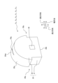
- FIG. 1 is a perspective view of a wire sensor according to an embodiment of the present invention, in which a sensor unit disposed inside a housing is clearly shown by seeing through the housing.
- FIG. 2 is an exploded perspective view of the housing.
- FIG. 3 is a perspective view of the sensor unit.
- 4(a) and 4(b) are explanatory diagrams showing the arrangement of the sensor unit in the housing.
- Fig. 4(a) shows the inside of the housing as viewed from the positive side in the Y direction
- Fig. 4(b) shows the inside of the housing as viewed from the negative side in the X direction.
- FIG. 5 is an explanatory diagram showing the positional relationship between the tops and guide grooves of each of the six sensor units arranged in the housing.
- Fig. 1 is a perspective view of a wire sensor according to an embodiment of the present invention, in which a sensor unit disposed inside a housing is clearly shown by seeing through the housing.
- FIG. 2 is an exploded perspective view of the housing.
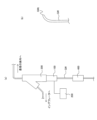
- FIG. 6(a) is an explanatory diagram showing the arrangement of devices at the doctor's hand when performing catheter treatment
- Fig. 6(b) is a plan view showing the shape of the tip of a guide wire.
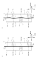
- 7(a) and 7(b) are explanatory diagrams for explaining the principle of force detection in a guidewire.
- Fig. 7(a) shows the state of the preload applied to the sensor unit abutting against the guidewire in the X direction when no force is applied in the longitudinal direction of the guidewire.
- Fig. 7(b) shows the state of the load applied to the sensor unit abutting against the guidewire in the X direction when force is applied in the longitudinal direction of the guidewire.
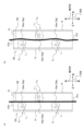
- FIGS. 8(a) and 8(b) are explanatory diagrams for explaining the principle of force detection in a guidewire.
- Fig. 8(a) shows the state of a preload applied to a sensor unit abutting against a guidewire in the Y direction when no force is applied in the longitudinal direction of the guidewire.
- Fig. 8(b) shows the state of a load applied to a sensor unit abutting against a guidewire in the Y direction when force is applied in the longitudinal direction of the guidewire.
- 9(a) and 9(b) are explanatory diagrams for explaining preload.
- Fig. 9(a) shows a state in which no force is applied to the wire sensor in the longitudinal direction of the guide wire.
- Fig. 9(b) shows a state in which force is applied to the wire sensor in the longitudinal direction of the guide wire.
- the wire sensor 100 mainly includes a rectangular housing 10 and six sensor units S X1 , S X2 , S X3 , S Y1 , S Y2 , and S Y3 housed inside the housing 10 .
- the longitudinal direction of the housing 10 will be referred to as the axial direction below.
- One direction in an orthogonal plane perpendicular to the axial direction is the X direction
- the direction perpendicular to the X direction in the orthogonal plane is the Y direction.
- the axial direction, X direction, and Y direction are mutually perpendicular.
- the axial direction is the direction extending between the lower left and upper right of the page
- the X direction is the direction extending between the upper left and lower right of the page
- the Y direction is the direction extending vertically on the page.
- the front and rear sides of the axial direction, the positive and negative sides of the X direction, and the positive and negative sides of the Y direction are defined as shown in FIG. 1.
- the axial direction is an example of a first direction
- the X direction is an example of a second direction
- the Y direction is an example of a third direction.
- the housing 10 is a box that houses six sensor units inside and forms the external appearance of the wire sensor 100.
- the housing 10 is made of resin, metal, etc.
- the housing 10 is a rectangular parallelepiped having a central axis CA extending in the axial direction.
- the housing 10 has a first plate 11 located at the front side in the axial direction, a second plate 12 located at the rear side in the axial direction, a third plate 13 located at the positive side in the X direction, a fourth plate 14 located at the negative side in the X direction, a fifth plate 15 located at the positive side in the Y direction, and a sixth plate 16 located at the negative side in the Y direction.
- the first plate 11 and the second plate 12 are each perpendicular to the axial direction.
- the third plate 13 and the fourth plate 14 are each perpendicular to the X direction.
- the fifth plate 15 and the sixth plate 16 are each perpendicular to the Y direction.
- the first plate 11 is a square flat plate.
- a pinhole (opening) PH1 is formed in the center of the first plate 11, penetrating the first plate 11 in the axial direction. When viewed in the axial direction, the center of the pinhole PH1 is located on the central axis CA.
- a slit SL1 extending in the Y direction is formed in the center of the first plate 11 in the X direction. One end of the slit SL1 opens to the edge of the first plate 11 on the positive side in the Y direction, and the other end of the slit SL1 communicates with the pinhole PH1.
- the second plate 12 is a square flat plate.
- a pinhole (opening) PH2 is formed in the center of the second plate 12, penetrating the second plate 12 in the axial direction. When viewed in the axial direction, the center of the pinhole PH2 is located on the central axis CA.
- a slit SL2 extending in the Y direction is formed in the center of the second plate 12 in the X direction. One end of the slit SL2 opens to the side of the second plate 12 on the positive side in the Y direction, and the other end of the slit SL2 communicates with the pinhole PH2.
- the third plate 13 and the fourth plate 14 are rectangular flat plates whose long sides run in the axial direction and whose short sides run in the Y direction.
- the fifth plate 15 and the sixth plate 16 are rectangular flat plates whose long sides run in the axial direction and whose short sides run in the X direction.
- the first plate 11, the second plate 12, the third plate 13, the fourth plate 14, and the sixth plate 16 are fixedly connected to each other to form a bathtub-shaped structure (a box shape with one side open).
- the fifth plate 15 is detachable from the bathtub-shaped structure.
- the six sensor units S X1 , S X2 , S X3 , S Y1 , S Y2 , and S Y3 have the same configuration as one another.
- Each of the six sensor units S X1 , S X2 , S X3 , S Y1 , S Y2 , and S Y3 has a strain body 20 and a strain gauge 30 attached to the strain body 20, as shown in FIG.
- the strain body 20 is a member that generates strain when it receives a load from a guide wire GW (described later) that passes through the inside of the housing 10.
- the strain body 20 is formed, for example, from resin, metal, etc.
- the strain body 20 has a rectangular base 21 and a thick semicircular head 22.
- the direction in which the base 21 and head 22 are aligned is called the height direction
- the longitudinal direction of the base 21 is called the length direction
- the direction perpendicular to the height direction and length direction is called the width direction.
- the upper surface of the head 22 is the top surface 20a of the strain generating body 20.
- the top surface 20a is a curved surface that curves in an arc shape along the length direction so that it is convex upward in the height direction.
- a guide groove 20g that extends in the length direction is formed in the center in the width direction at the apex (contact portion) 20at (the uppermost position in the height direction) of the top surface 20a.
- the lower surface of the base portion 21 is the bottom surface (base) 20b of the strain generating body 20.
- the strain gauges 30 are attached to one side and the other side of the width direction of the base 21, one on each side. When the wire sensor 100 is in use, the strain gauges 30 are connected to the control unit 200 ( Figure 6(a)) by wiring (not shown).
- the lengthwise dimension of the lower end of the head 22 is greater than the lengthwise dimension of the upper end of the base 21. Therefore, at the connection between the base 21 and the head 22, a protrusion 20p is formed where the head 22 protrudes from the base 21 on both sides in the lengthwise direction.
- the sensors S X1 and S X3 are fixed to the fourth plate 14 of the housing 10. Specifically, the sensor unit S X1 is fixed near the axial front end of the fourth plate 14 with the bottom surface 20b of the strain body 20 abutting against the inner side of the fourth plate 14. The sensor unit S X3 is fixed near the axial rear end of the fourth plate 14 with the bottom surface 20b of the strain body 20 abutting against the inner side of the fourth plate 14.
- the height direction of the sensor units S X1 and S X3 coincides with the X direction of the wire sensor 100, and the length direction and width direction of the sensor units S X1 and S X3 coincide with the axial direction and Y direction, respectively, of the wire sensor 100.
- the guide grooves 20g of the sensor units S X1 and S X3 extend in the axial direction.
- the sensor units S X1 and S X3 are disposed inside the housing 10 with the top 20at of the top surface 20a of the strain body 20 facing the positive side in the X direction.
- the sensor unit S 102 is fixed to the third plate 13 of the housing 10. Specifically, the sensor unit S 102 is fixed near the center of the third plate 13 in the axial direction with the bottom surface 20b of the strain body 20 abutting against the inner surface of the third plate 13.
- the height direction of the sensor unit S 12 coincides with the X direction of the wire sensor 100, and the length direction and width direction of the sensor unit S 12 coincide with the axial direction and Y direction, respectively, of the wire sensor 100.
- the guide groove 20g of the sensor unit S 12 extends in the axial direction.
- the sensor unit S 12 is disposed inside the housing 10 with the top portion 20at of the top surface 20a of the strain body 20 facing the negative side in the X direction.
- the sensor units S Y1 and S Y3 are fixed to the fifth plate 15 of the housing 10. Specifically, the sensor unit S Y1 is fixed near the axial front end of the fifth plate 15 with the bottom surface 20b of the strain body 20 abutting against the inner side of the fifth plate 15. The sensor unit S Y3 is fixed near the axial rear end of the fifth plate 15 with the bottom surface 20b of the strain body 20 abutting against the inner side of the fifth plate 15.
- the height direction of the sensor units S Y1 and S Y3 coincides with the Y direction of the wire sensor 100, and the length direction and width direction of the sensor units S Y1 and S Y3 coincide with the axial direction and X direction, respectively, of the wire sensor 100.
- the guide grooves 20g of the sensor units S Y1 and S Y3 extend in the axial direction.
- the sensor units S Y1 and S Y3 are disposed inside the housing 10 with the top 20at of the top surface 20a of the strain body 20 facing the negative side in the Y direction.
- the sensor unit S Y2 is fixed to the sixth plate 16 of the housing 10. Specifically, the sensor unit S Y2 is fixed near the center of the sixth plate 16 in the axial direction with the bottom surface 20b of the strain body 20 abutting against the inner surface of the sixth plate 16.
- the height direction of the sensor part S Y2 coincides with the Y direction of the wire sensor 100, and the length direction and width direction of the sensor part S Y2 coincide with the axial direction and X direction, respectively, of the wire sensor 100.
- the guide groove 20g of the sensor part S Y2 extends in the axial direction.
- the sensor part S Y2 is disposed inside the housing 10 with the top part 20at of the top surface 20a of the strain body 20 facing the positive side in the Y direction.
- the sensors S X1 , S X2 , S X3 , S Y1 , S Y2 and S Y3 are arranged in the axial direction in the order of sensor unit S X1 , sensor unit S Y1 , sensor unit S X2 , sensor unit S Y2 , sensor unit S X3 and sensor unit S Y3 .
- the sensor units S X1 , S X2 , and S X3 are arranged in this order along the axial direction from the front to the rear in the axial direction.
- the sensor unit S X2 is located at the center of the sensor units S X1 and S X3 . Therefore, in the axial direction, the distance from the longitudinal center of the sensor unit S X1 to the longitudinal center of the sensor unit S X2 is equal to the distance from the longitudinal center of the sensor unit S X2 to the longitudinal center of the sensor unit S X3 .
- the top 20at (and guide groove 20g) of the flexure body 20 of sensor unit S X1 and sensor unit S X3 is located on the positive side in the X direction of the central axis CA of the housing 10, and the top 20at (and guide groove 20g) of the flexure body 20 of sensor unit S X2 is located on the negative side in the X direction of the central axis CA of the housing 10. That is, each of sensor units S X1 , S X2 , and S X3 is provided such that the top 20at (and guide groove 20g) of the flexure body 20 is located on the opposite side in the X direction to the bottom surfaces 20b of the first and second pinholes PH1 and PH2.
- the sensor units S Y1 , S Y2 , and S Y3 are arranged in this order along the axial direction from the front to the rear in the axial direction.
- the sensor unit S Y2 is located at the center of the sensor units S Y1 and S Y3 . Therefore, in the axial direction, the distance from the center of the sensor unit S Y1 to the center of the sensor unit S Y2 is equal to the distance from the center of the sensor unit S Y2 to the center of the sensor unit S Y3 .
- the top 20at (and guide groove 20g) of the flexure body 20 of sensor unit S Y1 and sensor unit S Y3 is located on the negative side in the Y direction from the central axis CA of the housing 10, and the top 20at (and guide groove 20g) of the flexure body 20 of sensor unit S Y2 is located on the positive side in the Y direction from the central axis CA of the housing 10. That is, each of sensor units S Y1 , S Y2 , and S Y3 is provided such that the top 20at (and guide groove 20g) of the flexure body 20 is located on the opposite side in the Y direction from the bottom surfaces 20b of the first and second pinholes PH1 and PH2.
- the apex 20at (and guide groove 20g) of each of the six sensor units S X1 , S X2 , S X3 , S Y1 , S Y2 , and S Y3 is disposed at a position shifted in a predetermined direction from the central axis CA.
- the apex 20at (and guide groove 20g) of each of the six sensor units S X1 , S X2 , S X3 , S Y1 , S Y2 , and S Y3 is located on a circumference centered on the central axis CA when viewed in the axial direction.
- the guide groove 20g of the sensor unit S X1 can be seen.
- the guide grooves 20g of the other sensor units are located behind the sensor unit S X1 and therefore cannot be seen.
- a method of using the wire sensor 100 will be described taking as an example a case where the wire sensor 100 is used in vascular catheter treatment in which a catheter is inserted into a blood vessel.
- a doctor inserts a metal wire called a guidewire into a patient's blood vessel and then inserts a catheter along the guidewire.
- the wire sensor 100 is used to detect (sense) the force applied in the longitudinal direction of the guidewire when the guidewire is fed into the patient's blood vessel.
- Figure 6(a) shows the equipment configuration at the doctor's hand when inserting the guidewire GW into the patient's body and sending it to the affected area.
- the guidewire GW extends into the patient's body, passing through the torquer 400, the wire sensor 100, and the Y-connector 300, in that order from the position closest to the doctor.
- the wire sensor 100 is attached to the Y - connector 300 while being connected to a control unit 200 that receives the outputs of the strain gauges 30 of the six sensor units S X1 , S X2 , S X3 , S Y1 , S Y2 , and S Y3 .
- a branch pipe of the Y-connector 300 is connected to an indeflator (not shown) for expanding and contracting the balloon.
- the torquer 400 has, for example, a built-in collet chuck (not shown).
- the torquer 400 is configured to easily transition between a gripping state in which the collet chuck grips the guidewire GW and a release state in which the collet chuck releases the grip of the guidewire GW.
- the guide wire GW can be placed on the wire sensor 100, for example, as follows:
- the fifth plate 15 (FIG. 1) is removed, and a guide wire GW is placed in the pinholes PH1 and PH2 through the slit SL1 in the first plate 11 and the slit SL2 in the second plate 12. Then, the guide wire GW extending between the pinholes PH1 and PH2 is placed in the guide grooves 20g of each of the four sensor units S X1 , S X2 , S X3 , and S Y2 . Finally, the fifth plate 15 is attached. At this time, the guide wire GW extending between the pinholes PH1 and PH2 is placed in the guide grooves 20g of each of the two sensor units S Y1 and S Y3 fixed to the fifth plate 15.
- the guidewire GW is housed inside the guide sensor 100 in a state of extending along the central axis CA.
- the strain bodies 20 of the sensor units S X1 and S X3 abut against the guidewire GW arranged inside the housing 10 from the negative side in the X direction (FIG. 7(a)).
- the strain body 20 of the sensor unit S X2 abuts against the guidewire GW arranged inside the housing 10 from the positive side in the X direction (FIG. 7(a)).
- the strain body 20 of the sensor units S Y1 and S Y3 abuts against the guidewire GW arranged inside the housing 10 from the positive side in the Y direction (FIG. 8(a)).
- the strain body 20 of the sensor unit S Y2 abuts against the guidewire GW arranged inside the housing 10 from the negative side in the Y direction (FIG. 8(a)).
- the apex 20at (and guide groove 20g) of the flexure body 20 of sensor unit S X1 and sensor unit S X3 is located on the positive side of the central axis CA of the housing 10 in the X direction
- the apex 20at (and guide groove 20g) of the flexure body 20 of sensor unit S X2 is located on the negative side of the central axis CA of the housing 10 in the X direction. Therefore, as shown in Fig. 7(a), loads (loads) L X1 and L X3 are applied to the sensor units S X1 and S X3 by the guide wire GW toward the negative side in the X direction.
- a load L X2 is applied to the sensor unit S X2 by the guide wire GW toward the positive side in the X direction.
- the tops 20at (and guide grooves 20g) of the flexure bodies 20 of sensor units S Y1 and S Y3 are located on the negative side of the central axis CA of the housing 10 in the Y direction
- the tops 20at (and guide grooves 20g) of the flexure bodies 20 of sensor unit S Y2 are located on the positive side of the central axis CA of the housing 10 in the Y direction. Therefore, as shown in Fig. 8(a), loads L Y1 and L Y3 are applied to sensor units S Y1 and S Y3 by the guide wire GW toward the positive side of the Y direction. Also, a load L Y2 is applied to sensor unit S Y2 by the guide wire GW toward the negative side of the Y direction.
- a load applied from the guidewire to the sensor units in a state in which the guidewire is not deflected in response to the application of an external force (external force to be detected) i.e., a state in which no external force to be detected is applied to the guidewire
- the preload can be applied, for example, by a force that causes a linear member such as a wire arranged in a curved (bent) state to return to its original linear shape.
- the doctor injects a contrast agent into the patient's blood vessels and advances the guidewire GW to the affected area while checking the position of the blood vessels on an X-ray.
- the area near the tip GWt of the guidewire GW is curved as shown in Figure 6(b).
- the doctor rotates the guidewire GW to change the direction of the tip GWt, and feeds the guidewire GW along the desired path within the blood vessel until the tip GWt of the guidewire reaches the affected area.
- a doctor inserts the guidewire GW into the patient's body while holding the torquer 400 in his right hand and the Y-connector 300 in his left hand.
- the doctor releases the torquer 400, picks up the guidewire GW, and moves it in the forward direction (the direction approaching the affected area).
- the doctor releases the torquer 400, picks up the guidewire GW, and moves it in the return direction (the direction approaching the outside of the body).
- the doctor holds the torquer 400 and rotates it.
- the guidewire GW bends.
- the wire sensor 100 detects the force applied in the longitudinal direction of the guidewire GW based on the fact that the values of the loads LX1 , LX2 , LX3 , LY1 , LY2 , LY3 that the guidewire GW applies to the sensor portions SX1 , SX2 , SX3 , SY1 , SY2 , SY3 change in response to the bending of the guidewire GW.
- the values of the loads LX1 , LX3 that the guidewire GW applies to the sensors S X1 , S X3 may decrease, and the value of the load LX2 that the guidewire GW applies to the sensor unit S X2 may increase.
- the values of the loads L Y1 , L Y3 that the guidewire GW applies to the sensors S Y1 , S Y3 may decrease, and the value of the load L Y2 that the guidewire GW applies to the sensor unit S Y2 may increase.
- the control unit 200 calculates the magnitude of the force applied in the longitudinal direction of the guidewire GW based on the changes in the values of the loads LX1 , LX2 , LX3 , LY1 , LY2 , and LY3 . Note that the manner in which the guidewire GW is bent and the manner in which the values of the loads LX1 , LX2 , LX3 , LY1 , LY2 , and LY3 are changed as shown in Fig. 7B and Fig. 8B are merely examples.
- the magnitude of the force detected by the wire sensor 100 indicates, for example, the magnitude of the force required to feed the guidewire GW.
- the magnitude of the force detected by the wire sensor 100 may be displayed on a display unit (not shown), for example, to assist a doctor in manipulating the guidewire GW.
- the change in the magnitude of the force detected by the wire sensor 100 over time may be stored as data in a memory unit (not shown).
- the guidewire GW accommodated in the wire sensor 100 is in contact with the strain bodies 20 of the sensor units S X1 , S X2 , S X3 , S Y1 , S Y2 , and S Y3 . Therefore, the sensor units S X1 , S X2 , S X3 , S Y1 , S Y2 , and S Y3 can immediately detect bending of the guidewire GW when bending occurs. Therefore, the wire sensor 100 can suitably ( satisfactorily) detect the force applied to the guidewire GW based on the bending of the guidewire GW in response to the application of the force.
- the wire sensor 100 of this embodiment includes both sensor units S X1 , S X2 , and S X3 that face the guidewire GW along the X direction and abut against the guidewire GW, and sensor units S Y1 , S Y2 , and S Y3 that face the guidewire GW along the Y direction and abut against the guidewire GW. Therefore, no matter in what direction the guidewire GW bends in response to the application of a force to be detected to the guidewire GW (i.e., even if the bending occurs only in the X direction or only in the Y direction), it is possible to detect the application of the force to be detected to the guidewire GW. Therefore, it is possible to suitably detect the force applied to the guidewire GW based on the bending of the guidewire GW in response to the application of the force.
- the wire sensor 100 of this embodiment houses the guidewire GW in a state in which the guidewire GW applies a preload to each of the sensor portions S , S , S , S, S, and S. Therefore, regardless of the manner in which the guidewire GW bends in response to the application of a force to be detected to the guidewire GW, the application of the force to be detected to the guidewire GW can be more suitably detected.
- Fig. 9(a) For example, as shown in Fig. 9(a), consider a wire sensor 500 that houses a guidewire GW in a state where no preload is applied from the guidewire GW to each of the sensor units (only sensor units S X1 , S X2 , and S X3 are shown in Fig. 9(a)).
- Fig. 9(b) if the deflection generated in the guidewire GW is in a mode of moving away from each sensor unit (only sensor units S X1 , S X2 , and S X3 are shown in Fig. 9(b)), the load applied to each sensor unit remains zero even though the guidewire GW is deflected (i.e., the force to be detected is applied to the guidewire GW).
- the guide sensor 100 of the present embodiment is configured such that the guidewire GW applies a preload to each sensor portion, so that when a force to be detected is applied to the guidewire GW, the values of the loads LX1 , LX2 , LX3 , LY1 , LY2 , and LY3 change regardless of the state of bending of the guidewire GW. Therefore, the force applied to the guidewire GW can be more suitably detected based on the bending of the guidewire GW in response to the application of the force.
- the strain bodies 20 of the sensor units S X1 , S X2 , S X3 , S Y1 , S Y2 , and S Y3 each have a guide groove 20g. Therefore, the guide wire GW can be held and guided inside the housing 10 in an excellent manner.
- the fifth plate 15 of the housing 10 is removable. Therefore, the guide wire GW can be easily placed inside the wire sensor 100 while visually checking the inside of the housing 10.
- slits SL1 and SL2 for guiding the guidewire GW to the pinholes PH1 and PH2 are formed in the first plate 11 and the second plate 12. Therefore, even if the end of the guidewire GW cannot be inserted into the pinholes PH1 and PH2, for example, when one end of the guidewire GW has already been inserted into the patient's body, the guidewire GW can be positioned in the pinholes PH1 and PH2 using the slits SL1 and SL2.
- the wire sensor 100 of the above embodiment may also be modified as follows.
- the housing 10 is a rectangular prism, but is not limited to this.
- the housing 10 may have any structure, such as a triangular prism, polygonal prism, or cylinder, that has a space inside in which the sensor unit is placed.
- the housing 10 does not necessarily have to be long in the axial direction.
- the fifth plate 15 is removable, but this is not limited to the above.
- the housing 10 may be in any form in which a part of the housing 10 is movable relative to other parts of the housing 10, and the interior of the housing 10 can be viewed by moving this part.
- the housing 10 may be a box in which the first plate 11 to the sixth plate 16 are all connected in an inseparable manner.
- at least one of the slits SL1 and SL2 may be omitted.
- the wire sensor 100 is used with the housing 10 attached to the Y-shaped connector 300, but this is not limited to the above.
- a handle extending from the housing 10 to the outside of the housing 10 may be provided.
- a user using the wire sensor 100 may operate the torquer 400 with his/her right hand and hold the handle extending from the housing 10 with his/her left hand.
- a user of the wire sensor 100 may hold the wire sensor 100 by directly gripping the housing 10. However, by holding the housing 10 via the Y-shaped connector 300 or a handle, it is possible to suppress the occurrence of distortion and temperature changes in the first plate 11 to the sixth plate 16 of the housing 10. This makes it possible to suppress the influence on detection in the sensor units S X1 , S X2 , S X3 , S Y1 , S Y2 , and S Y3 .
- the shape of the strain body 20 of the sensor units S X1 , S X2 , S X3 , S Y1 , S Y2 , and S Y3 is arbitrary.
- the strain body 20 may be a cylinder, a triangular prism, a square prism, any polygonal prism, etc. extending in the height direction.
- the strain body 20 does not need to have the guide groove 20g.
- strain gauges 30 are attached to the strain body 20 of each of the sensor units S X1 , S X2 , S X3 , S Y1 , S Y2 , and S Y3 , but this is not limited to this.
- the number of strain gauges 30 attached to the strain body 20 of each of the sensor units S X1 , S X2 , S X3 , S Y1 , S Y2 , and S Y3 is arbitrary.
- the wire sensor 100 of the above embodiment is provided with three sensor units S X1 , S X2 , and S X3 that abut against the guidewire GW along the X direction, and three sensor units S Y1 , S Y2 , and S Y3 that abut against the guidewire GW along the Y direction.
- the number of sensor units may be more or less than that of the above embodiment.
- each of the six sensor units S X1 , S X2 , S X3 , S Y1 , S Y2 , and S Y3 includes a strain body 20 and a strain gauge 30, but this is not limited to this.
- the strain gauge 30 may be omitted in at least one of the six sensor units S X1 , S X2 , S X3 , S Y1 , S Y2 , and S Y3 .
- the strain body 20 to which the strain gauge 30 is not attached essentially acts as a support unit that supports the guide wire GW.
- the sensor units S X1 , S X2 , S X3 , S Y1 , S Y2 , and S Y3 are configured to be preloaded, but are not limited to this.
- Each of the sensor units S X1 , S X2 , S X3 , S Y1 , S Y2 , and S Y3 may be configured to abut against the guidewire GW (the guidewire GW in a state where no force to be detected is applied) extending between the first pinhole PH1 and the second pinhole PH2 without receiving a preload from the guidewire GW.
- the bend when the guidewire GW is bent, the bend can be detected immediately, and the force applied to the guidewire GW can be suitably detected.
- the sensor units S X1 , S X2 , S X3 , S Y1 , S Y2 , and S Y3 may be configured to be positioned with a gap from the guidewire GW (the guidewire GW in a state where no force to be detected is applied) extending between the first pinhole PH1 and the second pinhole PH2.
- the deflection of the guidewire GW can be detected by the sensor units arranged in the X and Y directions, and the force applied to the guidewire GW can be suitably detected.
- the wire sensor 100 of the above embodiment may have only one of the three sensor units S X1 , S X2 , and S X3 and one of the three sensor units S Y1 , S Y2 , and S Y3 . In this case as well, it is possible to detect the application of a force in the longitudinal direction of the guidewire GW regardless of the direction in which the guidewire GW is bent, and it is possible to suitably detect the force applied in the longitudinal direction of the guidewire GW.
- the wire sensor 100 of the above embodiment may have only one of the six sensor units S, S , S , S , S, S.
- the force applied to the guidewire GW can be suitably detected based on the configuration in which the guidewire GW that is not subjected to the force to be detected abuts against the sensor unit or the configuration in which a preload is applied.
- control unit 200 may be provided integrally with the wire sensor 100 as a part of the wire sensor 100.
- control unit 200 may be provided inside the housing 10 or on the outer surface of the housing 10.
- the detection of the force to be detected may be the detection of the magnitude of the force to be detected (detection of the magnitude of the force applied to the guidewire GW) and/or the presence or absence of the force to be detected (presence or absence of force being applied to the guidewire GW).
- the wire sensor 100 is used with a guidewire GW used in vascular catheter treatment.
- the use of the wire sensor 100 is not limited to this, and the wire sensor 100 can be used with any linear member.
- the wire sensor 100 can be used with an endoscope cable.
- a wire means a linear member that has flexibility. Endoscope cables and the like are also included in the wires of the present invention.
- the present invention is not limited to the above-described embodiment, and other forms that are conceivable within the scope of the technical concept of the present invention are also included within the scope of the present invention.
- 10 Housing; 20: Strain generating body; 30: Strain gauge; 100: Wire sensor; 200: Control unit; GW: Guide wire; PH1, PH2: Pinhole; S X1 , S X2 , S X3 , S Y1 , S Y2 , S Y3 : Sensor unit
Landscapes
- Health & Medical Sciences (AREA)
- Life Sciences & Earth Sciences (AREA)
- Biophysics (AREA)
- Pulmonology (AREA)
- Engineering & Computer Science (AREA)
- Anesthesiology (AREA)
- Biomedical Technology (AREA)
- Heart & Thoracic Surgery (AREA)
- Hematology (AREA)
- Animal Behavior & Ethology (AREA)
- General Health & Medical Sciences (AREA)
- Public Health (AREA)
- Veterinary Medicine (AREA)
- Media Introduction/Drainage Providing Device (AREA)
- Force Measurement Appropriate To Specific Purposes (AREA)
Abstract
ワイヤ(GW)に加わった力を検出するワイヤセンサ(100)は、第1方向に延びる前記ワイヤを収容する筐体(10)と、前記筐体内に収容された前記ワイヤに対して前記第1方向に直交する第2方向の一方側に位置するように前記筐体内に設けられた第1起歪体(20)と、前記筐体内に収容された前記ワイヤに対して前記第1方向及び前記第2方向に直交する第3方向の一方側に位置するように前記筐体内に設けられた第2起歪体(20)と、前記第1起歪体に貼り付けられた第1ひずみゲージ(30)と、前記第2起歪体に貼り付けられた第2ひずみゲージ(30)とを備える。
Description
本発明は、ワイヤセンサに関する。
カテーテルと呼ばれる柔軟で細長い管を患者の体内に挿入して患部に処置を施すカテーテル治療が広く行われている。具体的には例えば、血管にカテーテルを挿入するバルーン治療、ステント治療等が行われている。バルーン治療では、カテーテルを介してバルーンを膨らますことにより、患部(例えば血管の狭窄が生じている箇所)を拡張する。ステント治療では、バルーンで拡張した箇所にステント(金属の網)を留置することにより、患部に再び狭窄が生じることを抑制する。
カテーテル治療において、医師は、カテーテルを患者の体内に挿入する前にまずガイドワイヤと呼ばれる金属製のワイヤを患者の体内に挿入する。そしてその後、ガイドワイヤに沿ってカテーテルを挿入する。
ここで、ガイドワイヤとともに使用するセンサとして、特許文献1は、ワイヤ状部材が貫通し、内部において前記ワイヤ状部材の湾曲を許容するように形成された貫通穴を含むワイヤ通過部と、前記ワイヤ状部材の湾曲部分が前記貫通穴の内壁に作用する力を検出する荷重検出部とを備えるセンサを開示している。
本発明は、ワイヤ状(線状)の部材に加わる力を好適に検出することのできるワイヤセンサを提供することを目的とする。
本発明の第1の態様に従えば、
ワイヤに加わった力を検出するワイヤセンサであって、
第1方向に延びる前記ワイヤを収容する筐体と、
前記筐体内に収容された前記ワイヤに対して前記第1方向に直交する第2方向の一方側に位置するように前記筐体内に設けられた第1起歪体と、
前記筐体内に収容された前記ワイヤに対して前記第1方向及び前記第2方向に直交する第3方向の一方側に位置するように前記筐体内に設けられた第2起歪体と、
前記第1起歪体に貼り付けられた第1ひずみゲージと、
前記第2起歪体に貼り付けられた第2ひずみゲージとを備えるワイヤセンサが提供される。
ワイヤに加わった力を検出するワイヤセンサであって、
第1方向に延びる前記ワイヤを収容する筐体と、
前記筐体内に収容された前記ワイヤに対して前記第1方向に直交する第2方向の一方側に位置するように前記筐体内に設けられた第1起歪体と、
前記筐体内に収容された前記ワイヤに対して前記第1方向及び前記第2方向に直交する第3方向の一方側に位置するように前記筐体内に設けられた第2起歪体と、
前記第1起歪体に貼り付けられた第1ひずみゲージと、
前記第2起歪体に貼り付けられた第2ひずみゲージとを備えるワイヤセンサが提供される。
本発明の第2の態様に従えば、
ワイヤに加わった力を検出するワイヤセンサであって、
第1方向に延びる前記ワイヤを収容する筐体と、
前記筐体内に収容された前記ワイヤに対して前記第1方向に直交する第2方向の一方側に位置するように前記筐体内に設けられた第1起歪体と、
前記第1起歪体に貼り付けられた第1ひずみゲージとを備え、
前記ワイヤに検出対象の力が加わっていない状態において、前記筐体内に収容された前記ワイヤが前記第1起歪体に当接するワイヤセンサが提供される。
ワイヤに加わった力を検出するワイヤセンサであって、
第1方向に延びる前記ワイヤを収容する筐体と、
前記筐体内に収容された前記ワイヤに対して前記第1方向に直交する第2方向の一方側に位置するように前記筐体内に設けられた第1起歪体と、
前記第1起歪体に貼り付けられた第1ひずみゲージとを備え、
前記ワイヤに検出対象の力が加わっていない状態において、前記筐体内に収容された前記ワイヤが前記第1起歪体に当接するワイヤセンサが提供される。
本発明のワイヤセンサによれば、ワイヤ状(線状)の部材に加わる力を好適に検出することができる。
<実施形態>
本発明の実施形態のワイヤセンサ100について、図1~図9を参照して説明する。
本発明の実施形態のワイヤセンサ100について、図1~図9を参照して説明する。
[ワイヤセンサ100の構造]
図1に示す通り、ワイヤセンサ100は、長方形の筐体10と、筐体10の内部に収容された6つのセンサ部SX1、SX2、SX3、SY1、SY2、SY3を主に有する。
図1に示す通り、ワイヤセンサ100は、長方形の筐体10と、筐体10の内部に収容された6つのセンサ部SX1、SX2、SX3、SY1、SY2、SY3を主に有する。
以下においては、説明の便宜上、筐体10の長手方向を軸方向と呼ぶ。また、軸方向に直交する直交面内の一方向をX方向とし、当該直交面内でX方向に直交する方向をY方向とする。軸方向、X方向、Y方向は互いに直交する。図1において、軸方向は紙面の左下と右上との間に延びる方向であり、X方向は紙面の左上と右下との間に延びる方向であり、Y方向は紙面の上下方向に延びる方向である。軸方向の前側、後側、X方向の正側、負側、Y方向の正側、負側を図1に記載する通り規定する。軸方向が第1方向の一例であり、X方向が第2方向の一例であり、Y方向が第3方向の一例である。
筐体10は、内部に6つのセンサ部を収容する箱体であり、ワイヤセンサ100の外観を構成するものである。筐体10は一例として、樹脂、金属等により形成される。
図1、図2に示す通り、筐体10は、軸方向に延びる中心軸CAを有する長方体である。筐体10は、軸方向の前側に位置する第1板11、軸方向の後側に位置する第2板12、X方向の正側に位置する第3板13、X方向の負側に位置する第4板14、Y方向の正側に位置する第5板15、及びY方向の負側に位置する第6板16を有する。第1板11、第2板12はそれぞれ、軸方向と直交している。第3板13、第4板14はそれぞれ、X方向と直交している。第5板15、第6板16はそれぞれ、Y方向と直交している。
第1板11は、正方形の平板である。第1板11の中心には、第1板11を軸方向に貫通するピンホール(開口)PH1が形成されている。軸方向に見て、ピンホールPH1の中心は中心軸CA上に位置する。第1板11のX方向の中央部には、Y方向に延びるスリットSL1が形成されている。スリットSL1の一端は第1板11のY方向正側の辺に開口しており、スリットSL1の他端はピンホールPH1に連通している。
第2板12は、正方形の平板である。第2板12の中心には、第2板12を軸方向に貫通するピンホール(開口)PH2が形成されている。軸方向に見て、ピンホールPH2の中心は中心軸CA上に位置する。第2板12のX方向の中央部には、Y方向に延びるスリットSL2が形成されている。スリットSL2の一端は第2板12のY方向正側の辺に開口しており、スリットSL2の他端はピンホールPH2に連通している。
第3板13、第4板14はそれぞれ、軸方向を長辺方向、Y方向を短辺方向とする矩形の平板である。第5板15、第6板16はそれぞれ、軸方向を長辺方向、X方向を短辺方向とする矩形の平板である。
本実施形態では、第1板11、第2板12、第3板13、第4板14、第6板16が互いに固定的に接続されて浴槽形(一方が開口した箱形)の構造を成している。第5板15は、当該浴槽形の構造に対して着脱可能である。
6つのセンサ部SX1、SX2、SX3、SY1、SY2、SY3は、互いに同一の構成を有する。6つのセンサ部SX1、SX2、SX3、SY1、SY2、SY3の各々は、図3に示す通り、起歪体20と、起歪体20に貼り付けられたひずみゲージ30とを有する。
起歪体20は、筐体10の内部を通過するガイドワイヤGW(後述)からの荷重を受けてひずみを生じる部材である。起歪体20は、一例として樹脂、金属等で形成されている。
図3に示す通り、起歪体20は、長方体の台部21と厚手の半円盤状の頭部22とを有する。起歪体20については、台部21と頭部22とが並ぶ方向を高さ方向、台部21の長手方向を長さ方向、高さ方向及び長さ方向に直交する方向を幅方向と呼ぶ。
頭部22の上面が、起歪体20の頂面20aである。頂面20aは、高さ方向の上方に凸となるように長さ方向に沿って円弧状に湾曲した曲面である。頂面20aの頂部(当接部)20at(高さ方向の最も上方の位置)には、幅方向の中央部に、長さ方向に延びるガイド溝20gが形成されている。台部21の下面が、起歪体20の底面(基部)20bである。
ひずみゲージ30は、台部21の幅方向の一方側の面及び他方側の面に、1つずつ貼り付けられている。ワイヤセンサ100の使用時には、ひずみゲージ30は、不図示の配線により制御部200(図6(a))に接続される。
本実施形態では、頭部22の下端部の長さ方向の寸法が、台部21の上端部の長さ方向の寸法よりも大きい。したがって、台部21と頭部22との接続部に、頭部22が台部21から長さ方向の両側に突出する突出部20pが形成されている。
図1に示す通り、センサ部SX1、SX3は、筐体10の第4板14に固定されている。具体的には、センサ部SX1は、起歪体20の底面20bを第4板14の内側面に当接させた状態で、第4板14の軸方向の前端近傍に固定されている。センサ部SX3は、起歪体20の底面20bを第4板14の内側面に当接させた状態で、第4板14の軸方向の後端近傍に固定されている。
センサ部SX1、SX3が第4板14に固定された状態において、センサ部SX1、SX3の高さ方向がワイヤセンサ100のX方向に一致しており、センサ部SX1、SX3の長さ方向、幅方向がそれぞれ、ワイヤセンサ100の軸方向、Y方向に一致している。センサ部SX1、SX3のガイド溝20gは軸方向に延びている。センサ部SX1、SX3は、筐体10の内部に、起歪体20の頂面20aの頂部20atをX方向の正側に向けて配置されている。
図1に示す通り、センサ部SX2は、筐体10の第3板13に固定されている。センサ部SX2は、具体的には、起歪体20の底面20bを第3板13の内側面に当接させた状態で、第3板13の軸方向の中央部近傍に固定されている。
センサ部SX2が第3板13に固定された状態において、センサ部SX2の高さ方向がワイヤセンサ100のX方向に一致しており、センサ部SX2の長さ方向、幅方向がそれぞれ、ワイヤセンサ100の軸方向、Y方向に一致している。センサ部SX2のガイド溝20gは軸方向に延びている。センサ部SX2は、筐体10の内部に、起歪体20の頂面20aの頂部20atをX方向の負側に向けて配置されている。
図1に示す通り、センサ部SY1、SY3は、筐体10の第5板15に固定されている。具体的には、センサ部SY1は、起歪体20の底面20bを第5板15の内側面に当接させた状態で、第5板15の軸方向の前端近傍に固定されている。センサ部SY3は、起歪体20の底面20bを第5板15の内側面に当接させた状態で、第5板15の軸方向の後端近傍に固定されている。
センサ部SY1、SY3が第5板15に固定された状態において、センサ部SY1、SY3の高さ方向がワイヤセンサ100のY方向に一致しており、センサ部SY1、SY3の長さ方向、幅方向がそれぞれ、ワイヤセンサ100の軸方向、X方向に一致している。センサ部SY1、SY3のガイド溝20gは軸方向に延びている。センサ部SY1、SY3は、筐体10の内部に、起歪体20の頂面20aの頂部20atをY方向の負側を向けて配置されている。
図1に示す通り、センサ部SY2は、筐体10の第6板16に固定されている。センサ部SY2は、具体的には、起歪体20の底面20bを第6板16の内側面に当接させた状態で、第6板16の軸方向の中央部近傍に固定されている。
センサ部SY2が第6板16に固定された状態において、センサ部SY2の高さ方向がワイヤセンサ100のY方向に一致しており、センサ部SY2の長さ方向、幅方向がそれぞれ、ワイヤセンサ100の軸方向、X方向に一致している。センサ部SY2のガイド溝20gは軸方向に延びている。センサ部SY2は、筐体10の内部に、起歪体20の頂面20aの頂部20atをY方向の正側に向けて配置されている。
センサ部SX1、SX2、SX3、SY1、SY2、SY3は、軸方向においては、センサ部SX1、センサ部SY1、センサ部SX2、センサ部SY2、センサ部SX3、センサ部SY3の順で並んでいる。
図4(a)に示す通り、センサ部SX1、SX2、SX3は、軸方向の前側から後側に向かって、軸方向に沿ってこの順番に並んでいる。軸方向において、センサ部SX2は、センサ部SX1、SX3の中央部に位置する。したがって、軸方向において、センサ部SX1の長さ方向中央部からセンサ部SX2の長さ方向中央部までの距離と、センサ部SX2の長さ方向中央部からセンサ部SX3の長さ方向中央部までの距離とは互いに等しい。
また、図4(a)に示す通り、センサ部SX1、センサ部SX3の起歪体20の頂部20at(及びガイド溝20g)は筐体10の中心軸CAよりもX方向正側に位置し、センサ部SX2の起歪体20の頂部20at(及びガイド溝20g)は筐体10の中心軸CAよりもX方向負側に位置する。即ち、センサ部SX1、SX2、SX3の各々は、起歪体20の頂部20at(及びガイド溝20g)が、X方向において、第1、第2ピンホールPH1、PH2の底面20bとは反対側に位置するように設けられている。
図4(b)に示す通り、センサ部SY1、SY2、SY3は、軸方向の前側から後側に向かって、軸方向に沿ってこの順番に並んでいる。軸方向において、センサ部SY2は、センサ部SY1、SY3の中央部に位置する。したがって、軸方向において、センサ部SY1の長さ方向中央部からセンサ部SY2の長さ方向中央部までの距離と、センサ部SY2の長さ方向中央部からセンサ部SY3の長さ方向中央部までの距離とは互いに等しい。
また、図4(b)に示す通り、センサ部SY1、センサ部SY3の起歪体20の頂部20at(及びガイド溝20g)は筐体10の中心軸CAよりもY方向負側に位置し、センサ部SY2の起歪体20の頂部20at(及びガイド溝20g)は筐体10の中心軸CAよりもY方向正側に位置する。即ち、センサ部SY1、SY2、SY3の各々は、起歪体20の頂部20at(及びガイド溝20g)が、Y方向において、第1、第2ピンホールPH1、PH2の底面20bとは反対側に位置するように設けられている。
このように、6つのセンサ部SX1、SX2、SX3、SY1、SY2、SY3の各々の頂部20at(及びガイド溝20g)は、中心軸CAから所定の方向にずれた位置に配置されている。図5に示す通り、6つのセンサ部SX1、SX2、SX3、SY1、SY2、SY3の各々の頂部20at(及びガイド溝20g)は、軸方向に見ると、中心軸CAを中心とする円周上に位置する。本実施形態では、軸方向の前側から見た場合、センサ部SX1のガイド溝20gのみを視認することができる。その他のセンサ部のガイド溝20gはセンサ部SX1の後ろに位置するため、視認することができない。
[ワイヤセンサ100の使用方法]
ワイヤセンサ100の使用方法を、血管にカテーテルを挿入する血管カテーテル治療においてワイヤセンサ100を用いる場合を例として説明する。
ワイヤセンサ100の使用方法を、血管にカテーテルを挿入する血管カテーテル治療においてワイヤセンサ100を用いる場合を例として説明する。
血管カテーテル治療において、医師は、ガイドワイヤと呼ばれる金属製のワイヤを患者の血管に挿入し、その後、ガイドワイヤに沿ってカテーテルを挿入する。ワイヤセンサ100は、ガイドワイヤを患者の血管内に送りこむ際に、ガイドワイヤの長手方向に加わる力を検出(検知)するために用いられる。
図6(a)は、ガイドワイヤGWを患者の体内に挿入し、患部へと送り込む際の、医師の手元の機器構成を示す。
ガイドワイヤGWは、医師の手元に近い位置から順番に、トルカー400、ワイヤセンサ100、Y字コネクタ300を通って、患者の体内へと延びる。ワイヤセンサ100は、6つのセンサ部SX1、SX2、SX3、SY1、SY2、SY3のひずみゲージ30の出力を受け取る制御部200に接続された状態で、Y字コネクタ300に取り付けられている。Y字コネクタ300の分岐管は、バルーンの拡張及び収縮を行うためのインデフレータ(不図示)に接続されている。
トルカー400は例えば、コレットチャック(不図示)を内蔵している。トルカー400は、コレットチャックによりガイドワイヤGWを把持した把持状態と、コレットチャックによるガイドワイヤGWの把持を解除した解除状態との間の変位を容易に行えるよう構成されている。
ワイヤセンサ100へのガイドワイヤGWの配置は、例えば次のようにして行うことができる。
まず、第5板15(図1)を取外し、第1板11のスリットSL1、第2板12のスリットSL2を介して、ピンホールPH1、PH2にガイドワイヤGWを配置する。そして、ピンホールPH1とピンホールPH2との間に延びるガイドワイヤGWを、4つのセンサ部SX1、SX2、SX3、SY2の各々のガイド溝20gに配置する。そして最後に、第5板15を取り付ける。この時、ピンホールPH1とピンホールPH2との間に延びるガイドワイヤGWが、第5板15に固定された2つのセンサ部SY1、SY3の各々のガイド溝20gに配置される。
これにより、ガイドワイヤGWは、ガイドセンサ100の内部に、中心軸CAに沿って延びた状態で収容される。この状態において、センサ部SX1、SX3の起歪体20は、筐体10の内部に配置されたガイドワイヤGWにX方向の負側から当接する(図7(a))。センサ部SX2の起歪体20は、筐体10の内部に配置されたガイドワイヤGWにX方向の正側から当接する(図7(a))。センサ部SY1、SY3の起歪体20は、筐体10の内部に配置されたガイドワイヤGWにY方向の正側から当接する(図8(a))。センサ部SY2の起歪体20は、筐体10の内部に配置されたガイドワイヤGWにY方向の負側から当接する(図8(a))。
ここで、上述の通り、センサ部SX1、センサ部SX3の起歪体20の頂部20at(及びガイド溝20g)は筐体10の中心軸CAよりもX方向正側に位置しており、センサ部SX2の起歪体20の頂部20at(及びガイド溝20g)は筐体10の中心軸CAよりもX方向負側に位置している。したがって、図7(a)に示す通り、センサ部SX1、SX3には、ガイドワイヤGWにより、X方向の負側に向けて荷重(負荷)LX1、LX3が加えられている。また、センサ部SX2には、ガイドワイヤGWにより、X方向の正側に向けて荷重LX2が加えられている。
同様に、上述の通り、センサ部SY1、センサ部SY3の起歪体20の頂部20at(及びガイド溝20g)は筐体10の中心軸CAよりもY方向負側に位置しており、センサ部SY2の起歪体20の頂部20at(及びガイド溝20g)は筐体10の中心軸CAよりもY方向正側に位置している。したがって、図8(a)に示す通り、センサ部SY1、SY3には、ガイドワイヤGWにより、Y方向の正側に向けて荷重LY1、LY3が加えられている。また、センサ部SY2には、ガイドワイヤGWにより、Y方向の負側に向けて荷重LY2が加えられている。
このように、ワイヤセンサ100のセンサ部SX1、SX2、SX3、SY1、SY2、SY3には、ガイドワイヤGWに外力(検出対象の外力)が加わっていない状態においても、ガイドワイヤGWからの荷重が加えられる。本発明及び本明細書において、ガイドワイヤに外力(検出対象の外力)の付加に応じた撓みが生じていない状態(則ちガイドワイヤに検出対象の外力が付加されていない状態)において、ガイドワイヤからセンサ部に与えられる荷重を、予荷重(予負荷)と呼ぶ。予荷重は例えば、湾曲(屈曲)して配置されたワイヤ等の線状部材が元の直線的な形状に戻ろうとする力により与えられ得る。
医師は、患者の血管内に造影剤を注入し、X線写真で血管の位置を把握しながらガイドワイヤGWを患部へと進める。ガイドワイヤGWの先端GWtの近傍の領域は、図6(b)に示すように湾曲している。医師は、ガイドワイヤGWを回転させて先端GWtの向きを変えながら、血管内の所望の経路に沿ってガイドワイヤGWを送り込み、ガイドワイヤの先端GWtを患部に至らせる。
医師は例えば、右手でトルカー400を、左手でY字コネクタ300を保持した状態で、ガイドワイヤGWを患者の体内に挿入していく。ガイドワイヤGWを患部へと進める際には、トルカー400を解除状態としてガイドワイヤGWを摘み、送り方向(患部に近づく方向)に移動させる。ガイドワイヤGWを患者の体外へと戻す際には、トルカー400を解除状態としてガイドワイヤGWを摘み、戻し方向(体外に近づく方向)に移動させる。ガイドワイヤGWの先端の向きを変える際には、トルカー400を把持状態としてトルカー400を回転させる。
この時、ガイドワイヤGWの長手方向に力が加わった場合、ガイドワイヤGWには撓みが生じる。ワイヤセンサ100は、ガイドワイヤGWがセンサ部SX1、SX2、SX3、SY1、SY2、SY3に加える荷重LX1、LX2、LX3、LY1、LY2、LY3の値がガイドワイヤGWの撓みに応じて変化することに基づいて、ガイドワイヤGWの長手方向に加わる力を検出する。
具体的には例えば、図7(b)に示す通り、ガイドワイヤGWの撓みに応じて、ガイドワイヤGWがセンサ部SX1、SX3に加える荷重LX1、LX3の値が小さくなり、ガイドワイヤGWがセンサ部SX2に加える荷重LX2の値が大きくなる場合がある。同様に、図8(b)に示す通り、ガイドワイヤGWの撓みに応じて、ガイドワイヤGWがセンサ部SY1、SY3に加える荷重LY1、LY3の値が小さくなり、ガイドワイヤGWがセンサ部SY2に加える荷重LY2の値が大きくなる場合がある。
制御部200は、荷重LX1、LX2、LX3、LY1、LY2、LY3の各々の値の変化に基づいて、ガイドワイヤGWの長手方向に加えられた力の大きさを算出する。なお、図7(b)、図8(b)に示すガイドワイヤGWの撓みの態様、及び荷重LX1、LX2、LX3、LY1、LY2、LY3の値の変化の態様は単なる一例である。ガイドワイヤGWには様々な態様の撓みが生じ、荷重LX1、LX2、LX3、LY1、LY2、LY3の各値は、ガイドワイヤGWの撓みの態様に応じた様々な変化を示す。
ワイヤセンサ100により検出された力の大きさは、例えば、ガイドワイヤGWを送るために要する力の大きさを示す。ワイヤセンサ100により検出された力の大きさは、例えば医師によるガイドワイヤGWの操作を補助するために、不図示の表示部に表示されてもよい。あるいは、ワイヤセンサ100により検出された力の大きさの変動の推移をデータとして不図示の記憶部に記憶してもよい。
本実施形態のワイヤセンサ100の有利な効果を以下にまとめる。
本実施形態のワイヤセンサ100は、ガイドワイヤGWに検出対象の力が加わっていない状態において、ワイヤセンサ100に収容されたガイドワイヤGWと、センサ部SX1、SX2、SX3、SY1、SY2、SY3の各々の起歪体20とが当接している。したがって、センサ部SX1、SX2、SX3、SY1、SY2、SY3は、ガイドワイヤGWに撓みが生じた際にはすぐに撓みを検出することができる。よって、ワイヤセンサ100は、ガイドワイヤGWに加わる力を、当該力の付加に応じたガイドワイヤGWに撓みに基づき好適(良好)に検出することが出来る。
本実施形態のワイヤセンサ100は、X方向に沿ってガイドワイヤGWと対向してガイドワイヤGWと当接するセンサ部SX1、SX2、SX3、及びY方向に沿ってガイドワイヤGWと対向してガイドワイヤGWと当接するセンサ部SY1、SY2、SY3の両方を備える。したがって、ガイドワイヤGWへの検出対象の力の付加に応じたガイドワイヤGWの撓みがどのような向きに生じていても(即ち、撓みがX方向又はY方向のみに生じていても)、ガイドワイヤGWに検出対象の力が加わったことを検出できる。したがって、ガイドワイヤGWに加わる力を、当該力の付加に応じたガイドワイヤGWに撓みに基づき好適に検出することが出来る。
本実施形態のワイヤセンサ100は、ガイドワイヤGWがセンサ部SX1、SX2、SX3、SY1、SY2、SY3の各々に予荷重を加えた状態でガイドワイヤGWを収容している。したがって、ガイドワイヤGWへの検出対象の力の付加に応じたガイドワイヤGWの撓みがどのような態様であっても、ガイドワイヤGWに検出対象の力が加わったことをより好適に検出できる。
この点につき、より詳しくは次の通りである。例えば図9(a)に示すように、ガイドワイヤGWから各センサ部(図9(a)ではセンサ部SX1、SX2、SX3のみを示す)の各々に予荷重を加えない状態でガイドワイヤGWを収容するワイヤセンサ500を考える。この場合、図9(b)のように、ガイドワイヤGWに生じた撓みが各センサ部(図9(b)ではセンサ部SX1、SX2、SX3のみを示す)から離間する態様であった場合、ガイドワイヤGWに撓みが生じている(則ち、ガイドワイヤGWに検出対象の力が加えられている)にもかかわらず、各センサ部に加えられる荷重はゼロのままである。
このように、本実施形態のガイドセンサ100は、ガイドワイヤGWが各センサ部に予荷重を加えるよう構成されているため、ガイドワイヤGWに検出対象の力が加わった場合、ガイドワイヤGWの撓みの態様にかかわらず荷重LX1、LX2、LX3、LY1、LY2、LY3の各値が変化する。したがって、ガイドワイヤGWに加わる力を、当該力の付加に応じたガイドワイヤGWに撓みに基づきより好適に検出することが出来る。
本実施形態のガイドセンサ100は、センサ部SX1、SX2、SX3、SY1、SY2、SY3の各々の起歪体20がガイド溝20gを有する。したがって、筐体10の内部におけるガイドワイヤGWの保持及び案内を良好に行うことが出来る。
本実施形態のガイドセンサ100は、筐体10の第5板15が取り外し可能である。したがって、ワイヤセンサ100の内部へのガイドワイヤGWの配置を、筐体10の内部を視認しながら容易に行うことができる。
本実施形態のガイドセンサ100は、第1板11、第2板12に、ピンホールPH1、PH2にガイドワイヤGWを案内するためのスリットSL1、SL2が形成されている。したがって例えば、ガイドワイヤGWの一端をすでに患者の体内に挿入している状況等、ガイドワイヤGWの端部をピンホールPH1、PH2に挿入できない場合であっても、スリットSL1、SL2を用いてピンホールPH1、PH2にガイドワイヤGWを配置することが出来る。
<変形例>
上記実施形態のワイヤセンサ100において、次の変形態様を用いることもできる。
上記実施形態のワイヤセンサ100において、次の変形態様を用いることもできる。
上記実施形態において、筐体10は長方体であるがこれには限られない。筐体10は、センサ部を配置する空間を内部に有する三角柱、多角柱、円柱等の任意の構造とし得る。筐体10は、必ずしも軸方向に長尺でなくてもよい。
上記実施形態の筐体10においては、第5板15が取り外し可能であるがこれには限られない。筐体10は、筐体10の一部が筐体10の他の部分に対して可動であり、当該一部を移動することにより筐体10の内部が視認可能となる任意の態様とし得る。或いは筐体10は、第1板11~第6板16の全てが分離不可能な状態で連結された箱体であってもよい。上記実施形態の筐体10において、スリットSL1、SL2の少なくとも一方を省略してもよい。
上記実施形態においては、筐体10をY字コネクタ300に取り付けた状態でワイヤセンサ100を用いているがこれには限られない。例えば、筐体10から筐体10の外側へと延びる把手を設けてもよい。この場合、ワイヤセンサ100を用いる使用者は、右手でトルカー400を操作し、左手で筐体10から延びる把手を保持してもよい。
なお、ワイヤセンサ100を用いる使用者は筐体10を直接把持することにより、ワイヤセンサ100を保持してもよい。しかしながら、Y字コネクタ300や把手を介して筐体10を保持することにより、筐体10の第1板11~第6板16におけるひずみや温度変化の発生を抑制することができる。これにより、センサ部SX1、SX2、SX3、SY1、SY2、SY3における検出への影響を抑制することができる。
上記実施形態のワイヤセンサ100において、センサ部SX1、SX2、SX3、SY1、SY2、SY3の起歪体20の形状は任意である。例えば、起歪体20は、高さ方向に延びる円柱、三角柱、四角柱、任意の多角柱等であってもよい。また、起歪体20はガイド溝20gを有さなくてもよい。
上記実施形態のワイヤセンサ100においては、センサ部SX1、SX2、SX3、SY1、SY2、SY3の各々の起歪体20に2つのひずみゲージ30が貼り付けられているがこれには限られない。センサ部SX1、SX2、SX3、SY1、SY2、SY3の各々の起歪体20に貼り付けるひずみゲージ30の数は任意である。
上記実施形態のワイヤセンサ100においては、X方向に沿ってガイドワイヤGWに当接する3つのセンサ部SX1、SX2、SX3と、Y方向に沿ってガイドワイヤGWに当接する3つのセンサ部SY1、SY2、SY3を設けている。しかしながら、センサ部の数は、上記実施形態よりも多くてもよく、少なくてもよい。
上記実施形態のワイヤセンサ100においては、6つのセンサ部SX1、SX2、SX3、SY1、SY2、SY3の各々が、起歪体20及びひずみゲージ30を備えるが、これには限られない。例えば、6つのセンサ部SX1、SX2、SX3、SY1、SY2、SY3の少なくとも一つにおいて、ひずみゲージ30を省略してもよい。この場合、ひずみゲージ30が取り付けられていない起歪体20は、実質的にはガイドワイヤGWを支持する支持部として作用する。
上記実施形態のワイヤセンサ100においては、センサ部SX1、SX2、SX3、SY1、SY2、SY3は、各々に予荷重がかかるように構成されているが、これには限られない。センサ部SX1、SX2、SX3、SY1、SY2、SY3の各々は、第1ピンホールPH1と第2ピンホールPH2との間に延びるガイドワイヤGW(検出対象の力が加わっていない状態のガイドワイヤGW)に対して、ガイドワイヤGWから予荷重を受けることなく当接するように構成されていてもよい。この態様でも、ガイドワイヤGWに撓みが生じた際にはすぐに撓みを検出することができ、ガイドワイヤGWに加わる力を好適に検出することが出来る。あるいは第1ピンホールPH1と第2ピンホールPH2との間に延びるガイドワイヤGW(検出対象の力が加わっていない状態のガイドワイヤGW)に対して隙間を有して位置するように構成されていてもよい。この態様でも、X方向及びY方向に配置されたセンサ部によりガイドワイヤGWの撓みを検出することができ、ガイドワイヤGWに加わる力を好適に検出することが出来る。
上記実施形態のワイヤセンサ100は、3つのセンサ部SX1、SX2、SX3のいずれか1つと、3つのセンサ部SY1、SY2、SY3のいずれか1つを有するのみでも良い。この場合も、ガイドワイヤGWの撓みがどのような向きに生じていてもガイドワイヤGWの長手方向に力が加わったこと検出でき、ガイドワイヤGWの長手方向に加わる力を好適に検出することが出来る。
上記実施形態のワイヤセンサ100は、6つのセンサ部SX1、SX2、SX3、SY1、SY2、SY3のいずれか1つを有するのみでも良い。この場合も、検出対象の力を受けないガイドワイヤGWがセンサ部に当接する構成、又は予荷重を加える構成に基づき、ガイドワイヤGWに加わる力を好適に検出することが出来る。
上記実施形態において、制御部200をワイヤセンサ100の一部としてワイヤセンサ100と一体に設けてもよい。例えば、制御部200を筐体10の内部、筐体10の外面に設けてもよい。
上記実施形態において、検出対象の力の検出は、検出対象の力の大きさの検出(ガイドワイヤGWに付加された力の大きさの検出)及び/又は検出対象の力の有無(ガイドワイヤGWへの力の付加の有無)であってよい。
上記実施形態においては、血管カテーテル治療に用いるガイドワイヤGWに対してワイヤセンサ100を用いる場合を例として説明した。しかしながらワイヤセンサ100の用途はこれには限られず、任意の線状部材に対してワイヤセンサ100を用いることができる。具体的には例えば、内視鏡のケーブルに対してワイヤセンサ100を用いることができる。本発明において、ワイヤとは可撓性を有する線状部材を意味する。内視鏡のケーブル等も本発明のワイヤに含まれる。
本発明の特徴を維持する限り、本発明は上記実施の形態に限定されるものではなく、本発明の技術的思想の範囲内で考えられるその他の形態についても、本発明の範囲内に含まれる。
10: 筐体; 20: 起歪体; 30: ひずみゲージ; 100: ワイヤセンサ; 200: 制御部; GW: ガイドワイヤ; PH1、PH2: ピンホール; SX1、SX2、SX3、SY1、SY2、SY3: センサ部
Claims (17)
- ワイヤに加わった力を検出するワイヤセンサであって、
第1方向に延びる前記ワイヤを収容する筐体と、
前記筐体内に収容された前記ワイヤに対して前記第1方向に直交する第2方向の一方側に位置するように前記筐体内に設けられた第1起歪体と、
前記筐体内に収容された前記ワイヤに対して前記第1方向及び前記第2方向に直交する第3方向の一方側に位置するように前記筐体内に設けられた第2起歪体と、
前記第1起歪体に貼り付けられた第1ひずみゲージと、
前記第2起歪体に貼り付けられた第2ひずみゲージとを備えるワイヤセンサ。 - 前記ワイヤに検出対象の力が加わっていない状態において、前記筐体内に収容された前記ワイヤが前記第1起歪体及び/又は前記第2起歪体に当接する請求項1に記載のワイヤセンサ。
- 前記筐体内に収容された前記ワイヤが前記第1起歪体及び/又は前記第2起歪体に予荷重を加える請求項2に記載のワイヤセンサ。
- 前記筐体が、各々が前記筐体の内部と外部とを連通させる一対の開口であって、前記第1方向に並び且つ各々に前記ワイヤが配置される一対の開口を有し、
前記第1起歪体は、前記筐体に固定された第1基部及び前記ワイヤに当接する第1当接部を有し、且つ前記第2方向において前記一対の開口の前記第1基部とは反対側に前記第1当接部が位置するように設けられており、
前記第2起歪体は、前記筐体に固定された第2基部及び前記ワイヤに当接する第2当接部を有し、且つ前記第3方向において前記一対の開口の前記第2基部とは反対側に前記第2当接部が位置するように設けられている請求項3に記載のワイヤセンサ。 - 前記第1起歪体と前記第2起歪体とが、前記第1方向において互いに異なる位置に設けられた請求項1~4のいずれか一項に記載のワイヤセンサ。
- 前記第1起歪体及び/又は前記第2起歪体が、前記ワイヤを前記第1方向に沿ってガイドするガイド溝を有する請求項1~5のいずれか一項に記載のワイヤセンサ。
- 前記筐体内に収容された前記ワイヤに対して前記第2方向の他方側に位置するように前記筐体内に設けられた第3起歪体と、
前記筐体内に収容された前記ワイヤに対して前記第3方向の他方側に位置するように前記筐体内に設けられた第4起歪体と、
前記第3起歪体に貼り付けられた第3ひずみゲージと、
前記第4起歪体に貼り付けられた第4ひずみゲージとを更に備える請求項1~6のいずれか一項に記載のワイヤセンサ。 - 前記筐体内に収容された前記ワイヤに対して前記第2方向の一方側に位置するように前記筐体内に設けられた第5起歪体と、
前記筐体内に収容された前記ワイヤに対して前記第3方向の一方側に位置するように前記筐体内に設けられた第6起歪体と、
前記第5起歪体に貼り付けられた第5ひずみゲージと、
前記第6起歪体に貼り付けられた第6ひずみゲージとを更に備え
前記第1方向において、前記第3起歪体が前記第1起歪体と前記第5起歪体との間に設けられており、
前記第1方向において、前記第4起歪体が前記第2起歪体と前記第6起歪体との間に設けられている請求項7に記載のワイヤセンサ。 - ワイヤに加わった力を検出するワイヤセンサであって、
第1方向に延びる前記ワイヤを収容する筐体と、
前記筐体内に収容された前記ワイヤに対して前記第1方向に直交する第2方向の一方側に位置するように前記筐体内に設けられた第1起歪体と、
前記第1起歪体に貼り付けられた第1ひずみゲージとを備え、
前記ワイヤに検出対象の力が加わっていない状態において、前記筐体内に収容された前記ワイヤが前記第1起歪体に当接するワイヤセンサ。 - 前記筐体内に収容された前記ワイヤが前記第1起歪体に予荷重を加える請求項9に記載のワイヤセンサ。
- 前記第1起歪体が、前記ワイヤを前記第1方向に沿ってガイドするガイド溝を有する請求項9又は10に記載のワイヤセンサ。
- 前記筐体が、各々が前記筐体の内部と外部とを連通させる一対の開口であって、前記第1方向に並び且つ各々に前記ワイヤが配置される一対の開口を有し、
前記第1起歪体は、前記筐体に固定された第1基部及び前記ワイヤに当接する第1当接部を有し、且つ前記第2方向において前記一対の開口の前記第1基部とは反対側に前記第1当接部が位置するように設けられている請求項9~11のいずれか一項に記載のワイヤセンサ。 - 前記筐体に収容された前記ワイヤに対して前記第1方向及び前記第2方向に直交する第3方向の一方側に位置するように前記筐体内に設けられた第2起歪体と、
前記第2起歪体に貼り付けられた第2ひずみゲージとを更に備え、
前記第2起歪体は、前記筐体に固定された第2基部及び前記ワイヤに当接する第2当接部を有し、且つ前記第3方向において前記一対の開口の前記第2基部とは反対側に前記第2当接部が位置するように設けられている請求項12に記載のワイヤセンサ。 - 前記筐体に収容された前記ワイヤに対して前記第2方向の他方側に位置するように前記筐体内に設けられた第3起歪体と、
前記筐体に収容された前記ワイヤに対して前記第3方向の他方側に位置するように前記筐体内に設けられた第4起歪体と、
前記第3起歪体に貼り付けられた第3ひずみゲージと、
前記第4起歪体に貼り付けられた第4ひずみゲージとを更に備え、
前記第3起歪体は、前記筐体に固定された第3基部及び前記ワイヤに当接する第3当接部を有し、且つ前記第2方向において前記一対の開口の前記第3基部とは反対側に前記第3当接部が位置するように設けられており、
前記第4起歪体は、前記筐体に固定された第4基部及び前記ワイヤに当接する第4当接部を有し、且つ前記第3方向において前記一対の開口の前記第4基部とは反対側に前記第4当接部が位置するように設けられている請求項13に記載のワイヤセンサ。 - 前記筐体に収容された前記ワイヤに対して前記第2方向の一方側に位置するように前記筐体内に設けられた第5起歪体と、
前記筐体に収容された前記ワイヤに対して前記第3方向の一方側に位置するように前記筐体内に設けられた第6起歪体と、
前記第5起歪体に貼り付けられた第5ひずみゲージと、
前記第6起歪体に貼り付けられた第6ひずみゲージとを更に備え、
前記第5起歪体は、前記筐体に固定された第5基部及び前記ワイヤに当接する第5当接部を有し、且つ前記第2方向において前記一対の開口の前記第5基部とは反対側に前記第5当接部が位置するように設けられており、
前記第6起歪体は、前記筐体に固定された第6基部及び前記ワイヤに当接する第6当接部を有し、且つ前記第3方向において前記一対の開口の前記第6基部とは反対側に前記第6当接部が位置するように設けられており、
前記第1方向において、前記第3起歪体が前記第1起歪体と前記第5起歪体との間に設けられており、
前記第1方向において、前記第4起歪体が前記第2起歪体と前記第6起歪体との間に設けられている請求項14に記載のワイヤセンサ。 - 前記筐体の一部が前記筐体の他の部分に対して可動であり、前記一部を移動することにより前記筐体の内部が視認可能となる請求項1~15のいずれか一項に記載のワイヤセンサ。
- 前記筐体に、前記筐体内に前記ワイヤを収容するためのスリットが形成された請求項1~16のいずれか一項に記載のワイヤセンサ。
Applications Claiming Priority (2)
| Application Number | Priority Date | Filing Date | Title |
|---|---|---|---|
| JP2023-074546 | 2023-04-28 | ||
| JP2023074546A JP2024158917A (ja) | 2023-04-28 | 2023-04-28 | ワイヤセンサ |
Publications (1)
| Publication Number | Publication Date |
|---|---|
| WO2024225415A1 true WO2024225415A1 (ja) | 2024-10-31 |
Family
ID=93256549
Family Applications (1)
| Application Number | Title | Priority Date | Filing Date |
|---|---|---|---|
| PCT/JP2024/016372 Ceased WO2024225415A1 (ja) | 2023-04-28 | 2024-04-26 | ワイヤセンサ |
Country Status (2)
| Country | Link |
|---|---|
| JP (1) | JP2024158917A (ja) |
| WO (1) | WO2024225415A1 (ja) |
Citations (4)
| Publication number | Priority date | Publication date | Assignee | Title |
|---|---|---|---|---|
| JP2007202675A (ja) * | 2006-01-31 | 2007-08-16 | Nagoya Institute Of Technology | センサならびにそれを備えた医療装置および訓練装置 |
| JP2011517421A (ja) * | 2008-03-27 | 2011-06-09 | セント・ジュード・メディカル・エイトリアル・フィブリレーション・ディヴィジョン・インコーポレーテッド | ロボットカテーテル装置用カートリッジ |
| JP2014095885A (ja) * | 2012-10-09 | 2014-05-22 | Panasonic Corp | 力呈示装置、力呈示方法、並びに、力呈示プログラム |
| WO2023162629A1 (ja) * | 2022-02-25 | 2023-08-31 | キヤノン株式会社 | 連続体ロボットシステム、その制御方法及びプログラム |
-
2023
- 2023-04-28 JP JP2023074546A patent/JP2024158917A/ja active Pending
-
2024
- 2024-04-26 WO PCT/JP2024/016372 patent/WO2024225415A1/ja not_active Ceased
Patent Citations (4)
| Publication number | Priority date | Publication date | Assignee | Title |
|---|---|---|---|---|
| JP2007202675A (ja) * | 2006-01-31 | 2007-08-16 | Nagoya Institute Of Technology | センサならびにそれを備えた医療装置および訓練装置 |
| JP2011517421A (ja) * | 2008-03-27 | 2011-06-09 | セント・ジュード・メディカル・エイトリアル・フィブリレーション・ディヴィジョン・インコーポレーテッド | ロボットカテーテル装置用カートリッジ |
| JP2014095885A (ja) * | 2012-10-09 | 2014-05-22 | Panasonic Corp | 力呈示装置、力呈示方法、並びに、力呈示プログラム |
| WO2023162629A1 (ja) * | 2022-02-25 | 2023-08-31 | キヤノン株式会社 | 連続体ロボットシステム、その制御方法及びプログラム |
Also Published As
| Publication number | Publication date |
|---|---|
| JP2024158917A (ja) | 2024-11-08 |
Similar Documents
| Publication | Publication Date | Title |
|---|---|---|
| EP3410975B1 (en) | Instrument force sensor using strain gauges in a faraday cage | |
| EP2938253B1 (en) | Guidewire with an in-wall hypotube sensor mount and the associated manufacturing method | |
| JP4878526B2 (ja) | 可撓性線状体の圧縮力計測装置 | |
| US9523821B2 (en) | Fixture for shape-sensing optical fiber in a kinematic chain | |
| TWI458509B (zh) | 插入體內用導管 | |
| JP5933872B1 (ja) | 内視鏡 | |
| JP2002153465A (ja) | 超音波内視鏡 | |
| US20190053737A1 (en) | System and method of cancellation of source induced errors | |
| WO2024225415A1 (ja) | ワイヤセンサ | |
| JP5444522B1 (ja) | プローブ及び内視鏡 | |
| CN118717001A (zh) | 一种具有末端位置姿态及形状感知的内窥镜 | |
| CN108472074A (zh) | 用于传感器使能的医疗设备的连接器护罩 | |
| WO2018043483A1 (ja) | 圧力測定装置、ガイドワイヤ用コネクタ、ガイドワイヤ及びガイドワイヤの製造方法 | |
| JP2013192691A (ja) | 医療用チューブの制御ハンドルおよび医療用チューブの導入装置 | |
| WO2012098788A1 (ja) | 先端偏向操作可能カテーテル | |
| US11911004B2 (en) | Bending and extending device and bending and extending method | |
| JP7299348B2 (ja) | 医療器具把持器 | |
| EP1556925B1 (en) | Cable connector assembly and system | |
| JP5979720B2 (ja) | ガイドワイヤ成形器具 | |
| JP2009254463A (ja) | 内視鏡先端フード | |
| JP2020192267A (ja) | インサータ | |
| WO2021246287A1 (ja) | ガイドワイヤ | |
| JPWO2016189646A1 (ja) | 湾曲機構および軟性医療器具 | |
| WO2017010232A1 (ja) | 計測装置および医療機器、医療操作訓練装置 | |
| WO2019181102A1 (ja) | 先端偏向操作可能カテーテル |
Legal Events
| Date | Code | Title | Description |
|---|---|---|---|
| 121 | Ep: the epo has been informed by wipo that ep was designated in this application |
Ref document number: 24797160 Country of ref document: EP Kind code of ref document: A1 |
|
| NENP | Non-entry into the national phase |
Ref country code: DE |