WO2024225343A1 - プロジェクション溶接継手及びその製造方法 - Google Patents
プロジェクション溶接継手及びその製造方法 Download PDFInfo
- Publication number
- WO2024225343A1 WO2024225343A1 PCT/JP2024/016150 JP2024016150W WO2024225343A1 WO 2024225343 A1 WO2024225343 A1 WO 2024225343A1 JP 2024016150 W JP2024016150 W JP 2024016150W WO 2024225343 A1 WO2024225343 A1 WO 2024225343A1
- Authority
- WO
- WIPO (PCT)
- Prior art keywords
- less
- steel plate
- nut
- point
- current
- Prior art date
- Legal status (The legal status is an assumption and is not a legal conclusion. Google has not performed a legal analysis and makes no representation as to the accuracy of the status listed.)
- Ceased
Links
Images


Classifications
-
- C—CHEMISTRY; METALLURGY
- C22—METALLURGY; FERROUS OR NON-FERROUS ALLOYS; TREATMENT OF ALLOYS OR NON-FERROUS METALS
- C22C—ALLOYS
- C22C38/00—Ferrous alloys, e.g. steel alloys
- C22C38/60—Ferrous alloys, e.g. steel alloys containing lead, selenium, tellurium, or antimony, or more than 0.04% by weight of sulfur
-
- B—PERFORMING OPERATIONS; TRANSPORTING
- B23—MACHINE TOOLS; METAL-WORKING NOT OTHERWISE PROVIDED FOR
- B23K—SOLDERING OR UNSOLDERING; WELDING; CLADDING OR PLATING BY SOLDERING OR WELDING; CUTTING BY APPLYING HEAT LOCALLY, e.g. FLAME CUTTING; WORKING BY LASER BEAM
- B23K11/00—Resistance welding; Severing by resistance heating
- B23K11/16—Resistance welding; Severing by resistance heating taking account of the properties of the material to be welded
-
- B—PERFORMING OPERATIONS; TRANSPORTING
- B23—MACHINE TOOLS; METAL-WORKING NOT OTHERWISE PROVIDED FOR
- B23K—SOLDERING OR UNSOLDERING; WELDING; CLADDING OR PLATING BY SOLDERING OR WELDING; CUTTING BY APPLYING HEAT LOCALLY, e.g. FLAME CUTTING; WORKING BY LASER BEAM
- B23K11/00—Resistance welding; Severing by resistance heating
- B23K11/24—Electric supply or control circuits therefor
-
- C—CHEMISTRY; METALLURGY
- C22—METALLURGY; FERROUS OR NON-FERROUS ALLOYS; TREATMENT OF ALLOYS OR NON-FERROUS METALS
- C22C—ALLOYS
- C22C38/00—Ferrous alloys, e.g. steel alloys
- C22C38/002—Ferrous alloys, e.g. steel alloys containing In, Mg, or other elements not provided for in one single group C22C38/001 - C22C38/60
-
- C—CHEMISTRY; METALLURGY
- C22—METALLURGY; FERROUS OR NON-FERROUS ALLOYS; TREATMENT OF ALLOYS OR NON-FERROUS METALS
- C22C—ALLOYS
- C22C38/00—Ferrous alloys, e.g. steel alloys
- C22C38/008—Ferrous alloys, e.g. steel alloys containing tin
-
- C—CHEMISTRY; METALLURGY
- C22—METALLURGY; FERROUS OR NON-FERROUS ALLOYS; TREATMENT OF ALLOYS OR NON-FERROUS METALS
- C22C—ALLOYS
- C22C38/00—Ferrous alloys, e.g. steel alloys
- C22C38/02—Ferrous alloys, e.g. steel alloys containing silicon
-
- C—CHEMISTRY; METALLURGY
- C22—METALLURGY; FERROUS OR NON-FERROUS ALLOYS; TREATMENT OF ALLOYS OR NON-FERROUS METALS
- C22C—ALLOYS
- C22C38/00—Ferrous alloys, e.g. steel alloys
- C22C38/04—Ferrous alloys, e.g. steel alloys containing manganese
-
- C—CHEMISTRY; METALLURGY
- C22—METALLURGY; FERROUS OR NON-FERROUS ALLOYS; TREATMENT OF ALLOYS OR NON-FERROUS METALS
- C22C—ALLOYS
- C22C38/00—Ferrous alloys, e.g. steel alloys
- C22C38/06—Ferrous alloys, e.g. steel alloys containing aluminium
-
- C—CHEMISTRY; METALLURGY
- C22—METALLURGY; FERROUS OR NON-FERROUS ALLOYS; TREATMENT OF ALLOYS OR NON-FERROUS METALS
- C22C—ALLOYS
- C22C38/00—Ferrous alloys, e.g. steel alloys
- C22C38/18—Ferrous alloys, e.g. steel alloys containing chromium
- C22C38/34—Ferrous alloys, e.g. steel alloys containing chromium with more than 1.5% by weight of silicon
-
- C—CHEMISTRY; METALLURGY
- C22—METALLURGY; FERROUS OR NON-FERROUS ALLOYS; TREATMENT OF ALLOYS OR NON-FERROUS METALS
- C22C—ALLOYS
- C22C38/00—Ferrous alloys, e.g. steel alloys
- C22C38/18—Ferrous alloys, e.g. steel alloys containing chromium
- C22C38/40—Ferrous alloys, e.g. steel alloys containing chromium with nickel
- C22C38/42—Ferrous alloys, e.g. steel alloys containing chromium with nickel with copper
-
- C—CHEMISTRY; METALLURGY
- C22—METALLURGY; FERROUS OR NON-FERROUS ALLOYS; TREATMENT OF ALLOYS OR NON-FERROUS METALS
- C22C—ALLOYS
- C22C38/00—Ferrous alloys, e.g. steel alloys
- C22C38/18—Ferrous alloys, e.g. steel alloys containing chromium
- C22C38/40—Ferrous alloys, e.g. steel alloys containing chromium with nickel
- C22C38/44—Ferrous alloys, e.g. steel alloys containing chromium with nickel with molybdenum or tungsten
-
- C—CHEMISTRY; METALLURGY
- C22—METALLURGY; FERROUS OR NON-FERROUS ALLOYS; TREATMENT OF ALLOYS OR NON-FERROUS METALS
- C22C—ALLOYS
- C22C38/00—Ferrous alloys, e.g. steel alloys
- C22C38/18—Ferrous alloys, e.g. steel alloys containing chromium
- C22C38/40—Ferrous alloys, e.g. steel alloys containing chromium with nickel
- C22C38/46—Ferrous alloys, e.g. steel alloys containing chromium with nickel with vanadium
-
- C—CHEMISTRY; METALLURGY
- C22—METALLURGY; FERROUS OR NON-FERROUS ALLOYS; TREATMENT OF ALLOYS OR NON-FERROUS METALS
- C22C—ALLOYS
- C22C38/00—Ferrous alloys, e.g. steel alloys
- C22C38/18—Ferrous alloys, e.g. steel alloys containing chromium
- C22C38/40—Ferrous alloys, e.g. steel alloys containing chromium with nickel
- C22C38/48—Ferrous alloys, e.g. steel alloys containing chromium with nickel with niobium or tantalum
-
- C—CHEMISTRY; METALLURGY
- C22—METALLURGY; FERROUS OR NON-FERROUS ALLOYS; TREATMENT OF ALLOYS OR NON-FERROUS METALS
- C22C—ALLOYS
- C22C38/00—Ferrous alloys, e.g. steel alloys
- C22C38/18—Ferrous alloys, e.g. steel alloys containing chromium
- C22C38/40—Ferrous alloys, e.g. steel alloys containing chromium with nickel
- C22C38/50—Ferrous alloys, e.g. steel alloys containing chromium with nickel with titanium or zirconium
-
- C—CHEMISTRY; METALLURGY
- C22—METALLURGY; FERROUS OR NON-FERROUS ALLOYS; TREATMENT OF ALLOYS OR NON-FERROUS METALS
- C22C—ALLOYS
- C22C38/00—Ferrous alloys, e.g. steel alloys
- C22C38/18—Ferrous alloys, e.g. steel alloys containing chromium
- C22C38/40—Ferrous alloys, e.g. steel alloys containing chromium with nickel
- C22C38/54—Ferrous alloys, e.g. steel alloys containing chromium with nickel with boron
-
- C—CHEMISTRY; METALLURGY
- C22—METALLURGY; FERROUS OR NON-FERROUS ALLOYS; TREATMENT OF ALLOYS OR NON-FERROUS METALS
- C22C—ALLOYS
- C22C38/00—Ferrous alloys, e.g. steel alloys
- C22C38/18—Ferrous alloys, e.g. steel alloys containing chromium
- C22C38/40—Ferrous alloys, e.g. steel alloys containing chromium with nickel
- C22C38/58—Ferrous alloys, e.g. steel alloys containing chromium with nickel with more than 1.5% by weight of manganese
-
- B—PERFORMING OPERATIONS; TRANSPORTING
- B23—MACHINE TOOLS; METAL-WORKING NOT OTHERWISE PROVIDED FOR
- B23K—SOLDERING OR UNSOLDERING; WELDING; CLADDING OR PLATING BY SOLDERING OR WELDING; CUTTING BY APPLYING HEAT LOCALLY, e.g. FLAME CUTTING; WORKING BY LASER BEAM
- B23K11/00—Resistance welding; Severing by resistance heating
- B23K11/14—Projection welding
Definitions
- the present invention relates to a projection welded joint in which a steel plate and a nut having a protrusion are projection welded via the protrusion, and to a method for manufacturing the same.
- peel strength also simply called peel strength.
- peel strength As steel plates have become stronger in recent years, the joint between the steel plate and the nut tends to become brittle, making it difficult to ensure peel strength.
- Patent Document 1 describes a projection welded joint in which the area ratio between the joint and the nominal diameter part of the nut or bolt satisfies a specified relationship, and the maximum hardness of the joint and heat-affected zone is 550 HV or less. Furthermore, Patent Document 1 reports that high joint strength can be obtained by increasing the pressure during projection welding. Patent Document 2 reports that high joint strength can be obtained by tempering the joint by post-current application at a current value lower than the current value during welding after projection welding.
- the present invention aims to provide a projection welded joint with improved peel strength and a manufacturing method thereof.
- High-strength steel plates have a higher carbon content than conventional steel plates, and are more susceptible to embrittlement at the joint, which reduces the peel strength of projection-welded joints.
- it is effective to alleviate stress concentration by softening the joint surface between the nut and the steel plate to be welded.
- area b the area near the boundary between the steel plate and the nut and including part of the joint is designated as area b, and the peel strength can be improved by reducing the hardness of area b. This is because softening the hardness of area b improves the toughness of area b and further reduces residual stress.
- the gist of the present invention is as follows:
- a projection welded joint formed by projection welding a steel plate and a nut having a protrusion via the protrusion The steel plate comprises, in mass%, C: 0.05-0.50%, Si: 0.1-2.0%, Mn: 1.5-4.0%, P: 0.10% or less, S: 0.005% or less, N: 0.010% or less; and O: 0.030% or less, and optionally Al: 2.00% or less, B: 0.0050% or less, Ca: 0.005% or less, Cr: 1.00% or less, Cu: 0.80% or less, Ni: 1.00% or less, Mo: 1.00% or less, Ti: 0.200% or less, V: 0.500% or less, Nb: 0.080% or less, Sb: 0.200% or less; and Sn: 0.200% or less.
- the balance is composed of Fe and unavoidable impurities.
- a projection welded joint wherein the minimum hardness Hvb (HV) of the steel plate in a region b defined below and the base metal hardness Hvm (HV) of the steel plate satisfy the following formula (1).
- the region b is specified as follows in a cross section of the projection welded joint that includes the center line of the nut and passes through the center of the joint between the steel plate and the nut:
- An end point on the inner circumferential surface side of the nut that contacts the steel plate is defined as A
- an end point on the outer circumferential surface side is defined as B
- a point inside the steel plate that is moved 0.50 mm in the thickness direction of the steel plate from point B is defined as C
- a point inside the steel plate that is moved 0.50 mm in the thickness direction of the steel plate from point A is defined as D
- the inside of a rectangle formed by connecting points A, B, C, and D is defined as region b.
- a method for manufacturing a projection welded joint by projection welding a steel plate and a nut having a protrusion via the protrusion comprises, in mass%, C: 0.05-0.50%, Si: 0.1-2.0%, Mn: 1.5-4.0%, P: 0.10% or less, S: 0.005% or less, N: 0.010% or less; and O: 0.030% or less, and optionally Al: 2.00% or less, B: 0.0050% or less, Ca: 0.005% or less, Cr: 1.00% or less, Cu: 0.80% or less, Ni: 1.00% or less, Mo: 1.00% or less, Ti: 0.200% or less, V: 0.500% or less, Nb: 0.080% or less, Sb: 0.200% or less; and Sn: 0.200% or less.
- the balance is composed of Fe and unavoidable impurities.
- the projection welding is a main current application process in which a current is applied at a current value I1 (kA) for a current application time t1 (ms) to form a joint between the steel plate and the nut; a non-energization step of providing a non-energization period of a non-energization time t c1 (ms) that satisfies the following formula (2); a first post-current application step of applying current at a current value I2 (kA) that satisfies the following formula (3) for a current application time t2 (ms) that satisfies the following formula (4); a second post-current application step of applying current at a current value I 3 (kA) that satisfies the following formula (5) for a current application time t 3 (ms) that satisfies the following formula (6); A method for manufacturing a projection welded joint having the above structure. 400 ⁇
- the present invention can provide a projection welded joint with improved peel strength.
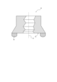
- FIG. 2 is a cross-sectional view including a center line of a nut used in one embodiment of the present invention.
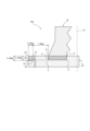
- 1 is a partial cross-sectional view of a projection welded joint according to one embodiment of the present invention, the cross-sectional view including the center line of a nut and passing through the center of a joint between a steel plate and a nut.
- 1A is a top view of a nut provided with three protrusions
- FIG. 1B is a top view of a nut provided with four protrusions, both used in one embodiment of the present invention.
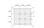
- FIG. 1 is a diagram showing region b and hardness measurement points in region b of a cross section of a projection welded joint according to one embodiment of the present invention.
- FIG. 1 is a diagram showing a measurement area 30 for base metal hardness Hvm and hardness measurement points in the area 30 in a cross section of a projection welded joint according to one embodiment of the present invention.
- C 0.05-0.50% C is an element that contributes to strengthening the steel plate. If the C content of the steel plate is less than 0.05%, the strength of the steel plate is low, and it is extremely difficult to manufacture a steel plate with a tensile strength of 780 MPa or more.
- the C content of the steel plate is set to 0.05% or more.
- the C content of the steel plate is preferably set to 0.10% or more.
- the C content of the steel plate exceeds 0.50%, the steel plate Although the strength is increased, the amount of hard martensite becomes excessive, and the number of microvoids increases. Furthermore, the joint becomes excessively hard and embrittlement progresses, making it difficult to improve the peel strength. Therefore,
- the C content of the steel plate is set to 0.50% or less, and preferably to 0.45% or less.
- the Si content of the steel sheet is 0.1% or more, the steel sheet is effectively strengthened.
- Si is a ferrite forming element, it is advantageous in forming ferrite at the end of the joint. Therefore, the Si content of the steel plate is set to 0.1% or more.
- the Si content of the steel plate is preferably set to 0.2% or more.
- the Si content of the steel plate exceeds 2.0%, although the steel plate is strengthened, it may have a negative effect on the toughness. Therefore, the Si content of the steel plate is set to 2.0% or less.
- the Si content is preferably set to 1.8% or less.
- Mn 1.5-4.0% If the Mn content is 1.5% or more, a high peel strength can be obtained without long-term cooling. Therefore, the Mn content of the steel sheet is set to 1.5% or more. On the other hand, if the Mn content of the steel plate exceeds 4.0%, embrittlement of the welded portion or cracks associated with the embrittlement become prominent, so that the peel strength is reduced. Therefore, the Mn content of the steel plate is set to 4.0% or less, and preferably to 3.5% or less.
- P 0.10% or less
- P is an inevitable impurity, but if the P content of the steel plate exceeds 0.10%, strong segregation appears at the end of the joint of the welded portion, making it difficult to improve the peel strength. Therefore, the P content of the steel plate is set to 0.10% or less.
- the P content of the steel plate is preferably 0.05% or less, and more preferably 0.02% or less.
- the lower limit of the P content of the steel plate is not particularly limited. However, since excessive reduction leads to an increase in costs, the P content of the steel plate is preferably 0.005% or more.
- S 0.005% or less
- S is an element that segregates at grain boundaries and embrittles the steel sheet, and is an element that is inevitably included.
- the S content of the steel sheet exceeds 0.005%, it reduces the sulfides and the local deformability of the steel sheet. Therefore, the S content of the steel sheet is set to 0.005% or less.
- the S content of the steel sheet is preferably 0.004% or less, and more preferably 0.003% or less.
- the lower limit of the S content of the steel sheet is not particularly limited. However, since excessive reduction leads to an increase in costs, the S content of the steel sheet is preferably 0.001% or more.
- N 0.010% or less
- N is an element that is inevitably contained, and if the N content of the steel plate exceeds 0.010%, the aging resistance of the steel plate is deteriorated. Therefore, the N content of the steel plate is set to 0.010% or less.
- the N content of the steel plate is preferably set to 0.008% or less.
- the lower limit of the N content of the steel plate is not particularly limited. However, since an excessive reduction leads to an increase in costs, the N content of the steel plate is preferably set to 0.001% or more.
- the O content of the steel plate is set to 0.030% or less.
- the O content of the steel plate is preferably set to 0.020% or less. There is no particular lower limit for the O content of the steel plate. However, since excessive reduction leads to an increase in costs, the O content of the steel plate is preferably set to 0.005% or more.
- the steel sheet used in the present invention may contain one or more elements selected from Al, B, Ca, Cr, Cu, Ni, Mo, Ti, V, Nb, Sb, and Sn, if necessary.
- the remainder of the composition is Fe and unavoidable impurities.
- Al 2.00% or less
- Al is an element that can control the structure by refining austenite grains, but adding a large amount of Al deteriorates toughness. Therefore, when adding Al, the Al content is set to 2.00% or less.
- the Al content is preferably set to 1.50% or less.
- the Al content is preferably set to 0.01% or more, and more preferably set to 1.20% or more.
- B 0.0050% or less
- B is an element that can improve hardenability and strengthen steel sheets, but if a large amount is added, the effect is saturated. Therefore, when B is added, the B content is set to 0.0050% or less.
- the B content is preferably set to 0.0010% or less.
- the B content is preferably set to 0.0003% or more.
- Ca 0.005% or less
- Ca is an element that can contribute to improving the workability of steel plate, but adding a large amount of Ca deteriorates toughness. Therefore, when Ca is added, the Ca content is set to 0.005% or less.
- the Ca content is preferably set to 0.004% or less.
- the lower limit of the Ca content is not particularly limited, but from the viewpoint of fully obtaining the effect of adding Ca, the Ca content is preferably set to 0.001% or more.
- Cr 1.00% or less
- Cr is an element that can improve the strength of the steel plate by improving the hardenability, but if added in large amounts, the toughness of the joint may deteriorate. Therefore, when Cr is added, the Cr content is set to 1.00% or less.
- the Cr content is preferably set to 0.80% or less.
- the lower limit of the Cr content is not particularly limited, but from the viewpoint of fully obtaining the effect of the addition of Cr, the Cr content is preferably set to 0.01% or more.
- Cu 0.80% or less
- Cu is an element that can contribute to improving the strength of the steel plate, but adding a large amount of Cu deteriorates the toughness. Therefore, when Cu is added, the Cu content is set to 0.80% or less.
- the Cu content is preferably set to 0.60% or less.
- the Cu content is preferably set to 0.006% or more.
- Ni 1.00% or less
- Ni is an element that can contribute to improving the strength of steel plate, but adding a large amount of Ni deteriorates toughness. Therefore, when Ni is added, the Ni content is set to 1.00% or less.
- the Ni content is preferably set to 0.80% or less.
- the lower limit of the Ni content is not particularly limited, but from the viewpoint of fully obtaining the effect of the addition of Ni, the Ni content is preferably set to 0.005% or more.
- Mo 1.00% or less
- Mo is an element that can contribute to improving the strength of steel plate, but adding a large amount of Mo deteriorates toughness. Therefore, when Mo is added, the Mo content is set to 1.00% or less.
- the Mo content is preferably set to 0.80% or less.
- the lower limit of the Mo content is not particularly limited, but from the viewpoint of fully obtaining the effect of adding Mo, the Mo content is preferably set to 0.006% or more.
- Ti 0.200% or less
- Ti is an element that can improve hardenability and strengthen the steel plate, but if added in large amounts, it forms carbides, which undergo precipitation hardening and significantly deteriorate toughness. Therefore, when Ti is added, the Ti content is set to 0.200% or less.
- the Ti content is preferably set to 0.150% or less.
- the Ti content is preferably set to 0.003% or more.
- V 0.500% or less
- V is an element that can strengthen steel by controlling the structure through precipitation hardening, but adding a large amount of V leads to deterioration of the toughness of the joint. Therefore, when V is added, the V content is set to 0.500% or less.
- the V content is preferably set to 0.300% or less.
- the lower limit of the V content is not particularly limited, but from the viewpoint of fully obtaining the effect of the addition of V, the V content is preferably set to 0.005% or more.
- Nb 0.080% or less
- Nb is an element that can improve the cross tensile strength and delayed fracture resistance after resistance welding by forming fine carbonitrides, but if added in a large amount, not only does it significantly reduce elongation but also significantly impairs toughness. Therefore, when Nb is added, the Nb content is set to 0.080% or less.
- the Nb content is preferably set to 0.070% or less, and more preferably set to 0.060% or less.
- the lower limit of the Nb content is not particularly limited, but from the viewpoint of fully obtaining the effect of the addition of Nb, the Nb content is preferably set to 0.005% or more.
- Sb 0.200% or less
- Sb is an element that can suppress nitridation and oxidation of the steel sheet surface, but adding a large amount of Sb reduces toughness. Therefore, when Sb is added, the Sb content is set to 0.200% or less. There is no particular lower limit for the Sb content, but from the viewpoint of fully obtaining the effect of the addition of Sb, the Sb content is preferably set to 0.002% or more.
- Sn 0.200% or less
- Sn is an element that can suppress nitridation and oxidation of the steel sheet surface, and adding Sn stabilizes the material, but adding a large amount of Sn reduces toughness. Therefore, when Sn is added, the Sn content is set to 0.200% or less.
- the lower limit of the Sn content is not particularly limited, but from the viewpoint of fully obtaining the effect of adding Sn, the Sn content is preferably set to 0.002% or more.
- the steel plate having the above-mentioned composition preferably has a tensile strength of 980 MPa or more, and more preferably 1180 MPa or more.
- the tensile strength of the steel plate is 980 MPa or more
- the carbon content is high, and when conventional projection welding is performed, there is a problem that the joint is easily embrittled and the push-in peel strength is reduced.
- the present invention even in the case of a high-strength steel plate having a tensile strength of 980 MPa or more, the hardness of region b is softened, and the stress concentration is alleviated, thereby suppressing the decrease in peel strength.
- the peel strength of the projection weld can be improved by reducing the residual stress in region b.
- the above-mentioned effect can be obtained even when a steel plate having a tensile strength of less than 980 MPa is used.
- the upper limit of the tensile strength of the steel plate is not particularly limited, but the tensile strength is generally 2000 MPa or less.
- the thickness of the steel plate is preferably 0.8 mm to 2.3 mm, considering that it is intended for general automotive steel plates.
- the steel sheet used in the present invention may have a plating layer on the surface of the steel sheet, and may be, for example, a steel sheet having a zinc plating layer (galvanized steel sheet).
- the zinc plating layer includes known zinc plating layers, such as a hot-dip galvanized layer, an electrolytic zinc plating layer, a Zn-Al plating layer, and a Zn-Ni layer.
- the steel sheet used in the present invention may also be a steel sheet having an alloyed zinc plating layer by performing an alloying process after performing a zinc plating process.
- the zinc plating layer may be formed on only one side of the steel sheet, or on both sides.
- FIG. 1 shows a cross section including a center line 12 of a nut 10 used in one embodiment of the present invention.
- the nut 10 has a protrusion 16 on a surface 14 perpendicular to the center line 12.
- two protrusions 16 are provided symmetrically at 180° intervals with the center line 12 as the rotation axis on the surface 14 perpendicular to the center line 12.
- the protrusions 16 may be provided at three or four points symmetrically with the center line 12 as the rotation axis.
- the shapes of the nut 10 and the protrusions 16 may be, for example, a square welded nut (1C type) and various protrusion shapes described in JIS B 1196:2010, respectively.
- the composition of the nut is not particularly limited, but for example, S25C (JIS G4051) may be used.
- the C content in the composition of the nut is 0.05 mass% or more
- the hardness of region b is preferably obtained. Therefore, the C content of the nut is preferably 0.05 mass% or more, and more preferably 0.07 mass% or more.
- the C content in the composition of the nut is 0.40 mass% or less
- the hardness of region b is preferably obtained. Therefore, the C content of the nut is preferably 0.40 mass% or less, and more preferably 0.38 mass% or less.
- the number of protrusions provided on the surface perpendicular to the center line of the nut used in the present invention is three or more.
- the number of protrusions provided on the surface perpendicular to the center line of the nut used in the present invention is four or less.
- the projection welded joint according to the present invention is a projection welded joint formed by projection welding the above-mentioned steel plate and nut via the protrusion of the nut to form a joint between the steel plate and the nut.
- the "joint between the steel plate and the nut” refers to the portion where the steel plate and the nut are joined by fusion joining or solid-state joining, and is a portion originating from the protrusion of the nut.
- the projection welded joint according to the present invention is characterized in that the minimum hardness Hvb (HV) of the steel plate in region b defined below and the base metal hardness Hvm (HV) of the steel plate satisfy the following formula (1). Hvb/Hvm ⁇ 0.90...(1)
- Figure 2 shows a cross section of a projection welded joint 100 according to one embodiment of the present invention, which includes the center line 12 of the nut 10 and passes through the center of the joint between the steel plate 20 and the nut 10.
- the end point on the inner peripheral side of the nut 10 that contacts the steel plate 20 is designated as A, and the end point on the outer peripheral side is designated as B.
- the point inside the steel plate 20 that is moved 0.50 mm from point B in the thickness direction of the steel plate 20 is designated as C
- the point inside the steel plate 20 that is moved 0.50 mm from point A in the thickness direction of the steel plate 20 is designated as D
- region b the inside of the rectangle formed by connecting points A, B, C, and D is designated as region b.
- Figure 2 also shows the measurement region 30 for the base material hardness Hvm.
- Figure 3 shows a top view of (a) a nut 10A having three protrusions 16 and (b) a nut 10B having four protrusions 16, which are used in one embodiment of the present invention.
- the cutting line shown in Figure 3 is a line passing through the center line of the nut and the center of the protrusions 16. After projection welding the steel plate and the nut, the projection welded joint is cut along the cutting line shown in Figure 3, thereby obtaining a cross section as shown in Figure 2.
- Hvb/Hvm of the projection welded joint according to the present invention is set to 0.90 or less.
- Hvb/Hvm is preferably 0.87 or less, and more preferably 0.85 or less.
- Hvb/Hvm is preferably 0.60 or more.
- the minimum hardness Hvb of region b is determined as follows.
- Figure 4 shows an enlarged view of region b.
- hardness measurement points 32 are set at 0.20 mm pitches in a direction perpendicular to the thickness direction of the steel plate from a point moved 0.20 mm or 0.40 mm in the direction from point B to point C.
- a measurement load of 300 gf is applied with an indenter for 15 seconds in accordance with JIS Z 2244 (2020), and the Vickers hardness is measured. The lowest value among the measurement results obtained is the minimum hardness Hvb of region b.
- the minimum hardness Hvb of region b is 300 HV or more, the softening effect can be suitably obtained in region b. Therefore, the minimum hardness Hvb of region b is preferably 300 HV or more, and more preferably 320 HV or more. On the other hand, when the minimum hardness Hvb of region b is 650 HV or less, the softening effect can be suitably obtained in region b. Therefore, the minimum hardness Hvb of region b is preferably 650 HV or less, and more preferably 600 HV or less.
- the base material hardness Hvm of the steel plate is obtained as follows. As shown in FIG. 2, in the cross section of the projection welded joint 100, a point E1 is located 7.00 mm away from point B on the line formed by the surface of the steel plate 20. A point E2 is located 0.60 mm away from point E1 on the line formed by the surface of the steel plate 20, a point E3 is located inside the steel plate 20 located 0.60 mm away from point E2 in the thickness direction of the steel plate 20, and a point E4 is located inside the steel plate 20 located 0.60 mm away from point E1 in the thickness direction of the steel plate 20. The inside of the square formed by connecting points E1, E2, E3, and E4 is the measurement area 30 of the base material hardness Hvm.
- FIG. 5 shows an enlarged view of the measurement area 30 of the base material hardness Hvm.
- the hardness measurement points 32 are set at 0.20 mm intervals in the thickness direction of the steel plate 20 and in the direction perpendicular to the thickness direction from a point 0.20 mm away from point E1.
- a measurement load of 300 gf is applied for 15 seconds with an indenter in accordance with JIS Z 2244 (2020), and the Vickers hardness is measured at each point.
- the average value obtained is the base material hardness Hvm.
- the base material hardness Hvm of the steel plate is measured at its cross section, so the presence or absence of a plating layer does not affect it.
- the base material hardness Hvm of the steel plate is 400HV or more, the softening effect can be suitably obtained in region b. Therefore, it is preferable that the base material hardness Hvm of the steel plate is 400HV or more.
- the base material hardness Hvm of the steel plate is 700HV or less, the softening effect can be suitably obtained in region b. Therefore, it is preferable that the base material hardness Hvm of the steel plate is 700HV or less, and it is more preferable that it is 650HV or less.
- the method for manufacturing a projection welded joint is a method for manufacturing a projection welded joint by projection welding a steel plate and a nut having a protrusion via the protrusion, the steel plate having the above-mentioned component composition, and the projection welding includes a main current application step of applying current at a current value I1 (kA) for a current application time t1 (ms) to form a joint between the steel plate and the nut, a non-current application step of providing a non-current application period of a non-current application time tc1 (ms) that satisfies the following formula (2), a first post-current application step of applying current at a current value I2 (kA) that satisfies the following formula (3) for a current application time t2 (ms) that satisfies the following formula (4), and a second post-current application step of applying current at a current value I3 (kA) that sati
- the main current application process is a process for forming a joint between a steel plate and a nut.
- a current is applied at a current value I1 for a current application time t1 to form a joint. Note that, as long as a joint can be formed, the conditions of the main current application process described below are not particularly limited.
- the current value I1 in the main current application process is 7.0 kA or more
- the steel plate and the nut can be suitably joined.
- the current value I1 is less than 7.0 kA, after joining the steel plate and the nut, when the center of the joint is cut and the cross section is checked with a microscope, a gap is often observed between the steel plate and the nut. Therefore, the current value I1 in the main current application process is preferably 7.0 kA or more, and more preferably 8.0 kA or more.
- the current value I1 is 30.0 kA or less, the joint expands too much, the molten metal splashes out to the outside of the nut as a splash, and the projection part of the nut is completely crushed and does not function as a joint. Therefore, the current value I1 is preferably 30.0 kA or less, and more preferably 28.0 kA or less.
- the energization time t 1 of the main energization step is 70 ms or more, the joint can be suitably and stably obtained. Therefore, the energization time t 1 of the main energization step is preferably 70 ms or more, more preferably 100 ms or more, and even more preferably 160 ms or more. On the other hand, when the energization time t 1 is 500 ms or less, the joint expands too much, the molten metal splashes out of the nut as a splash, and the projection part of the nut is completely crushed and does not function as a joint. This can be suitably prevented. Therefore, the energization time t 1 of the main energization step is preferably 500 ms or less, and more preferably 400 ms or less.
- the pressure applied in the main current application process is 3.0 kN or more, the current diameter is of an appropriate size, and the occurrence of splashing can be suitably prevented. Therefore, the pressure applied in the main current application process is preferably 3.0 kN or more, and more preferably 3.5 kN or more.
- the pressure applied in the main current application process is preferably 6.0 kN or less, and more preferably 5.5 kN or less. Note that the pressure applied may be limited by the capacity of the equipment used, so it may be adjusted as appropriate to obtain the required joint diameter.
- first de-energization step and first post-energization step After the main current step, the projection welded joint is subjected to a softening treatment, particularly to region b. Specifically, after the main current step, a de-current step, a first post-current step, and a second post-current step are performed. By softening region b, stress concentration during a peel test is alleviated and residual stress is reduced, thereby improving the peel strength.
- the projection welded joint is cooled to sufficiently lower the temperature of region b in order to obtain a softening effect.
- the welded portion is cooled by maintaining a de-energized state for a cooling time t c1 (ms) shown in formula (2). 400 ⁇ tc1 ⁇ 800...(2) If the cooling time t c1 of the first de-energization step is less than 400 ms, the effect of the first post-energization step cannot be obtained, and the joint may become an embrittled structure. Therefore, the cooling time t c1 is set to 400 ms or more.
- the cooling time t c1 is preferably set to 450 ms or more, and more preferably set to 500 ms or more.
- the cooling time t c1 exceeds 800 ms, the welding time becomes long, so the cooling time t c1 of the first de-energization step is set to 800 ms or less.
- a first post-current passing step is performed.
- current is passed to raise the temperature of region b to an appropriate temperature range.
- appropriate temperature range refers to a temperature range for softening the hardness of region b.
- current is passed at a current value I2 (kA) that satisfies the following formula (3) for a current passing time t2 (ms) that satisfies the following formula (4).
- region b can be softened by performing the first post-current step at a current value equal to or greater than that of the main current step.
- the post-current step reduces the hardness of region b, making it possible to alleviate the stress concentration applied to region b during the indentation peel test.
- the current value I2 of the first post-current process is set to I1 or more, and preferably to 1.10I1 or more .
- the current value I2 of the first post-current process exceeds 3.00I1 , the temperature of the region b is likely to exceed the Ac3 point (the temperature at which the transformation from ferrite to austenite is completed), and the region b will eventually become embrittled. As a result, the toughness of the joint cannot be obtained. Therefore, the current value I2 of the first post-current process is set to 3.00I1 or less, and preferably to 2.80I1 or less .
- the temperature is raised rapidly in a short time, so the current passing time t2 in the temperature raising process is set to 80 ms or more.
- the current passing time t2 is preferably set to 100 ms or more.
- the current passing time t2 is set to 250 ms or less, and preferably 220 ms or less.
- a second post-current step is performed in which current is applied at a current value I3 (kA) that satisfies the following formula (5) for a current application time t3 (ms) that satisfies the following formula (6).
- the current value I3 of the second post-current passing step is set to be less than I2 .
- the current value I3 is preferably set to 0.90I2 or less , and more preferably set to 0.80I2 or less.
- the current value I3 of the second post-current passing step is preferably set to 0.20I2 or more, and more preferably set to 0.30I2 or more.
- the second post-current process is a process for softening the region b, and in order to effectively soften the region b, the current conduction time is set to be the same as that of the first post-current process. Therefore, the current conduction time t3 of the second post-current process is set to 180 ms or more, and preferably 200 ms or more. On the other hand, for the same reason, the current conduction time t3 of the second post-current process is set to 1000 ms or less. The current conduction time t3 of the second post-current process is preferably 900 ms or less.
- a de-energization step and a post-current step may be repeated. This is preferable because repeating the de-energization step and the post-current step increases the effect of softening region b. On the other hand, if the de-energization step and the post-current step are repeated too many times, the effect becomes saturated, so the number of times the step is repeated is preferably less than 10 times, and more preferably less than 4 times.
- the projection welding method of the present invention can soften region b by appropriately controlling the welding conditions in the post heat treatment process, thereby mitigating stress concentration and reducing residual stress.
- the projection welded joint obtained by this welding method can improve the push-in peel strength. Therefore, even when welding steel plates that contain a relatively large amount of C in their composition, specifically high-strength steel plates with a tensile strength of 980 MPa or more and a C content of 0.05 to 0.50 mass % as described above, the peel strength can be further improved.
- a projection welded joint was produced by projection welding a steel plate and a nut.
- the test pieces used were steel plates (Steel Plates A to M) with tensile strengths of 780 MPa to 1800 MPa and thicknesses of 1.0 to 1.8 mm.
- Table 1 shows the tensile strength (TS), thickness, and composition of the steel plates A to M used. The remainder of the composition shown in Table 1 is Fe and unavoidable impurities, and "-" indicates that the content of that element is below the lower detection limit.
- Test pieces Cold-rolled steel sheets or GA steel sheets (galvannealed steel sheets) of each steel sheet were prepared as test pieces.
- the size of the test piece was 50 mm on the long side and 50 mm on the short side, and a hole with a diameter of 11 mm was drilled in the center of the test piece.
- an M8 welding nut was prepared with three protrusions symmetrically provided at 120° intervals on the center line of the nut.
- the test piece was set in the AC welding machine so that the center of the hole in the test piece and the center of the screw hole in the nut were aligned, and the welded body was obtained by welding under the welding conditions shown in Table 2.
- the steel type of the M8 welding nut was S25C (JIS G4051).
- the resistance welding conditions were welding using a servo motor pressure type single-phase AC (50 Hz) resistance welding machine attached to a welding gun, and a projection welded joint was produced.
- the pair of electrode tips used were flat electrodes with a diameter of 30 mm.
- a bolt was fixed into the nut hole of the resulting projection welded joint to prepare a bolted test specimen.
- the hardness and peel strength characteristics of the base material and area b of the obtained projection welded joints and bolted test pieces were measured using the method described below.
- the hardness of the base material and region b was measured as follows.
- the projection welded joint was cut at a position including the center line of the nut and passing through the center of the joint between the steel plate and the nut to obtain a test piece, which was ultrasonically cleaned and then filled with resin to obtain a sample.
- the plate thickness cross section of the obtained sample was polished and etched using a picric acid solution.
- the hardness measurement was performed on the plate thickness cross section of the sample after etching as described above, and the results are shown in Table 2.
- the projection welded joints of the invention examples were good welded joints with excellent peel strength. In contrast, good projection welded joints were not obtained in the comparative examples.
- the present invention can provide a projection welded joint with improved peel strength.
Landscapes
- Chemical & Material Sciences (AREA)
- Engineering & Computer Science (AREA)
- Mechanical Engineering (AREA)
- Materials Engineering (AREA)
- Metallurgy (AREA)
- Organic Chemistry (AREA)
- Heat Treatment Of Steel (AREA)
- Butt Welding And Welding Of Specific Article (AREA)
- Heat Treatment Of Articles (AREA)
Priority Applications (5)
| Application Number | Priority Date | Filing Date | Title |
|---|---|---|---|
| EP24797089.0A EP4656321A1 (en) | 2023-04-24 | 2024-04-24 | Projection welded joint and manufacturing method therefor |
| JP2024541743A JP7831611B2 (ja) | 2023-04-24 | 2024-04-24 | プロジェクション溶接継手及びその製造方法 |
| KR1020257028951A KR20250139379A (ko) | 2023-04-24 | 2024-04-24 | 프로젝션 용접 이음매 및 그 제조 방법 |
| CN202480027030.3A CN121001845A (zh) | 2023-04-24 | 2024-04-24 | 凸焊接头及其制造方法 |
| MX2025012415A MX2025012415A (es) | 2023-04-24 | 2025-10-16 | Union soldada por proyeccion y metodo para producir la misma |
Applications Claiming Priority (2)
| Application Number | Priority Date | Filing Date | Title |
|---|---|---|---|
| JP2023-071101 | 2023-04-24 | ||
| JP2023071101 | 2023-04-24 |
Publications (1)
| Publication Number | Publication Date |
|---|---|
| WO2024225343A1 true WO2024225343A1 (ja) | 2024-10-31 |
Family
ID=93256509
Family Applications (1)
| Application Number | Title | Priority Date | Filing Date |
|---|---|---|---|
| PCT/JP2024/016150 Ceased WO2024225343A1 (ja) | 2023-04-24 | 2024-04-24 | プロジェクション溶接継手及びその製造方法 |
Country Status (6)
| Country | Link |
|---|---|
| EP (1) | EP4656321A1 (https=) |
| JP (1) | JP7831611B2 (https=) |
| KR (1) | KR20250139379A (https=) |
| CN (1) | CN121001845A (https=) |
| MX (1) | MX2025012415A (https=) |
| WO (1) | WO2024225343A1 (https=) |
Citations (4)
| Publication number | Priority date | Publication date | Assignee | Title |
|---|---|---|---|---|
| JP2004050280A (ja) * | 2002-07-24 | 2004-02-19 | Aisin Takaoka Ltd | プロジェクション溶接方法 |
| JP2010116592A (ja) * | 2008-11-12 | 2010-05-27 | Kobe Steel Ltd | ナットプロジェクション溶接継手 |
| JP7020597B1 (ja) * | 2020-06-25 | 2022-02-16 | Jfeスチール株式会社 | プロジェクション溶接継手及びプロジェクション溶接方法 |
| WO2023047840A1 (ja) * | 2021-09-27 | 2023-03-30 | 日本製鉄株式会社 | リベット継手の製造方法、リベット継手、及び自動車部品 |
Family Cites Families (2)
| Publication number | Priority date | Publication date | Assignee | Title |
|---|---|---|---|---|
| JP5708350B2 (ja) | 2011-01-13 | 2015-04-30 | 新日鐵住金株式会社 | プロジェクション溶接継手およびその製造方法 |
| JP5834740B2 (ja) | 2011-10-04 | 2015-12-24 | 新日鐵住金株式会社 | プロジェクション溶接継手の製造方法 |
-
2024
- 2024-04-24 JP JP2024541743A patent/JP7831611B2/ja active Active
- 2024-04-24 WO PCT/JP2024/016150 patent/WO2024225343A1/ja not_active Ceased
- 2024-04-24 KR KR1020257028951A patent/KR20250139379A/ko active Pending
- 2024-04-24 CN CN202480027030.3A patent/CN121001845A/zh active Pending
- 2024-04-24 EP EP24797089.0A patent/EP4656321A1/en active Pending
-
2025
- 2025-10-16 MX MX2025012415A patent/MX2025012415A/es unknown
Patent Citations (4)
| Publication number | Priority date | Publication date | Assignee | Title |
|---|---|---|---|---|
| JP2004050280A (ja) * | 2002-07-24 | 2004-02-19 | Aisin Takaoka Ltd | プロジェクション溶接方法 |
| JP2010116592A (ja) * | 2008-11-12 | 2010-05-27 | Kobe Steel Ltd | ナットプロジェクション溶接継手 |
| JP7020597B1 (ja) * | 2020-06-25 | 2022-02-16 | Jfeスチール株式会社 | プロジェクション溶接継手及びプロジェクション溶接方法 |
| WO2023047840A1 (ja) * | 2021-09-27 | 2023-03-30 | 日本製鉄株式会社 | リベット継手の製造方法、リベット継手、及び自動車部品 |
Non-Patent Citations (1)
| Title |
|---|
| See also references of EP4656321A1 * |
Also Published As
| Publication number | Publication date |
|---|---|
| EP4656321A1 (en) | 2025-12-03 |
| CN121001845A (zh) | 2025-11-21 |
| MX2025012415A (es) | 2025-11-03 |
| JP7831611B2 (ja) | 2026-03-17 |
| JPWO2024225343A1 (https=) | 2024-10-31 |
| KR20250139379A (ko) | 2025-09-23 |
Similar Documents
| Publication | Publication Date | Title |
|---|---|---|
| RU2633414C2 (ru) | Точечно-сварное соединение и способ точечной сварки | |
| JP6447752B2 (ja) | 抵抗溶接部を有する自動車用部材 | |
| EP3736076B1 (en) | Resistance spot welding method, and method for producing resistance-spot-welded joint | |
| JP5142068B2 (ja) | 抵抗スポット溶接用高張力鋼板及びその接合方法 | |
| JP7468825B1 (ja) | 抵抗スポット溶接継手の製造方法 | |
| WO2023080076A1 (ja) | 抵抗スポット溶接部材およびその抵抗スポット溶接方法 | |
| WO2023063097A1 (ja) | 抵抗スポット溶接継手およびその抵抗スポット溶接方法 | |
| JP7327676B2 (ja) | 抵抗スポット溶接部材およびその抵抗スポット溶接方法 | |
| JP7473861B1 (ja) | 抵抗スポット溶接方法 | |
| WO2024127866A1 (ja) | 抵抗スポット溶接継手およびその抵抗スポット溶接方法 | |
| JP7473009B2 (ja) | 抵抗スポット溶接継手およびその抵抗スポット溶接方法 | |
| JP7560006B1 (ja) | プロジェクション溶接継手及びその製造方法 | |
| JP7831611B2 (ja) | プロジェクション溶接継手及びその製造方法 | |
| WO2024225344A1 (ja) | プロジェクション溶接継手及びその製造方法 | |
| JP7831612B2 (ja) | プロジェクション溶接継手及びその製造方法 | |
| JP5008173B2 (ja) | 抵抗溶接用高張力鋼板及びその接合方法 | |
| JP7480929B1 (ja) | 抵抗スポット溶接継手およびその抵抗スポット溶接方法 | |
| JP7823801B1 (ja) | 抵抗スポット溶接継手の製造方法 | |
| JP5008172B2 (ja) | 抵抗溶接用高張力鋼板及びその接合方法 | |
| WO2024127865A1 (ja) | 抵抗スポット溶接継手の製造方法 | |
| WO2024111224A1 (ja) | 抵抗スポット溶接方法 | |
| KR20240119314A (ko) | 프로젝션 용접 조인트 및 프로젝션 용접 방법 | |
| WO2026069947A1 (ja) | 抵抗スポット溶接継手の製造方法 |
Legal Events
| Date | Code | Title | Description |
|---|---|---|---|
| WWE | Wipo information: entry into national phase |
Ref document number: 2024541743 Country of ref document: JP |
|
| 121 | Ep: the epo has been informed by wipo that ep was designated in this application |
Ref document number: 24797089 Country of ref document: EP Kind code of ref document: A1 |
|
| ENP | Entry into the national phase |
Ref document number: 1020257028951 Country of ref document: KR Free format text: ST27 STATUS EVENT CODE: A-0-1-A10-A15-NAP-PA0105 (AS PROVIDED BY THE NATIONAL OFFICE) |
|
| WWE | Wipo information: entry into national phase |
Ref document number: 202517088107 Country of ref document: IN |
|
| WWE | Wipo information: entry into national phase |
Ref document number: 2501006985 Country of ref document: TH |
|
| WWE | Wipo information: entry into national phase |
Ref document number: MX/A/2025/012415 Country of ref document: MX |
|
| WWP | Wipo information: published in national office |
Ref document number: MX/A/2025/012415 Country of ref document: MX |
|
| NENP | Non-entry into the national phase |
Ref country code: DE |
|
| WWP | Wipo information: published in national office |
Ref document number: 202517088107 Country of ref document: IN |
|
| WWP | Wipo information: published in national office |
Ref document number: 2024797089 Country of ref document: EP |