WO2024225330A1 - ブランク、構造部材の製造方法、及び構造部材 - Google Patents
ブランク、構造部材の製造方法、及び構造部材 Download PDFInfo
- Publication number
- WO2024225330A1 WO2024225330A1 PCT/JP2024/016120 JP2024016120W WO2024225330A1 WO 2024225330 A1 WO2024225330 A1 WO 2024225330A1 JP 2024016120 W JP2024016120 W JP 2024016120W WO 2024225330 A1 WO2024225330 A1 WO 2024225330A1
- Authority
- WO
- WIPO (PCT)
- Prior art keywords
- blank
- steel
- steel plate
- coating
- structural member
- Prior art date
- Legal status (The legal status is an assumption and is not a legal conclusion. Google has not performed a legal analysis and makes no representation as to the accuracy of the status listed.)
- Ceased
Links
Images


Classifications
-
- B—PERFORMING OPERATIONS; TRANSPORTING
- B62—LAND VEHICLES FOR TRAVELLING OTHERWISE THAN ON RAILS
- B62D—MOTOR VEHICLES; TRAILERS
- B62D25/00—Superstructure or monocoque structure sub-units; Parts or details thereof not otherwise provided for
- B62D25/02—Side panels
-
- B—PERFORMING OPERATIONS; TRANSPORTING
- B21—MECHANICAL METAL-WORKING WITHOUT ESSENTIALLY REMOVING MATERIAL; PUNCHING METAL
- B21D—WORKING OR PROCESSING OF SHEET METAL OR METAL TUBES, RODS OR PROFILES WITHOUT ESSENTIALLY REMOVING MATERIAL; PUNCHING METAL
- B21D22/00—Shaping without cutting, by stamping, spinning, or deep-drawing
- B21D22/20—Deep-drawing
- B21D22/26—Deep-drawing for making peculiarly, e.g. irregularly, shaped articles
-
- C—CHEMISTRY; METALLURGY
- C23—COATING METALLIC MATERIAL; COATING MATERIAL WITH METALLIC MATERIAL; CHEMICAL SURFACE TREATMENT; DIFFUSION TREATMENT OF METALLIC MATERIAL; COATING BY VACUUM EVAPORATION, BY SPUTTERING, BY ION IMPLANTATION OR BY CHEMICAL VAPOUR DEPOSITION, IN GENERAL; INHIBITING CORROSION OF METALLIC MATERIAL OR INCRUSTATION IN GENERAL
- C23C—COATING METALLIC MATERIAL; COATING MATERIAL WITH METALLIC MATERIAL; SURFACE TREATMENT OF METALLIC MATERIAL BY DIFFUSION INTO THE SURFACE, BY CHEMICAL CONVERSION OR SUBSTITUTION; COATING BY VACUUM EVAPORATION, BY SPUTTERING, BY ION IMPLANTATION OR BY CHEMICAL VAPOUR DEPOSITION, IN GENERAL
- C23C2/00—Hot-dipping or immersion processes for applying the coating material in the molten state without affecting the shape; Apparatus therefor
- C23C2/04—Hot-dipping or immersion processes for applying the coating material in the molten state without affecting the shape; Apparatus therefor characterised by the coating material
- C23C2/06—Zinc or cadmium or alloys based thereon
-
- C—CHEMISTRY; METALLURGY
- C23—COATING METALLIC MATERIAL; COATING MATERIAL WITH METALLIC MATERIAL; CHEMICAL SURFACE TREATMENT; DIFFUSION TREATMENT OF METALLIC MATERIAL; COATING BY VACUUM EVAPORATION, BY SPUTTERING, BY ION IMPLANTATION OR BY CHEMICAL VAPOUR DEPOSITION, IN GENERAL; INHIBITING CORROSION OF METALLIC MATERIAL OR INCRUSTATION IN GENERAL
- C23C—COATING METALLIC MATERIAL; COATING MATERIAL WITH METALLIC MATERIAL; SURFACE TREATMENT OF METALLIC MATERIAL BY DIFFUSION INTO THE SURFACE, BY CHEMICAL CONVERSION OR SUBSTITUTION; COATING BY VACUUM EVAPORATION, BY SPUTTERING, BY ION IMPLANTATION OR BY CHEMICAL VAPOUR DEPOSITION, IN GENERAL
- C23C2/00—Hot-dipping or immersion processes for applying the coating material in the molten state without affecting the shape; Apparatus therefor
- C23C2/04—Hot-dipping or immersion processes for applying the coating material in the molten state without affecting the shape; Apparatus therefor characterised by the coating material
- C23C2/12—Aluminium or alloys based thereon
-
- C—CHEMISTRY; METALLURGY
- C23—COATING METALLIC MATERIAL; COATING MATERIAL WITH METALLIC MATERIAL; CHEMICAL SURFACE TREATMENT; DIFFUSION TREATMENT OF METALLIC MATERIAL; COATING BY VACUUM EVAPORATION, BY SPUTTERING, BY ION IMPLANTATION OR BY CHEMICAL VAPOUR DEPOSITION, IN GENERAL; INHIBITING CORROSION OF METALLIC MATERIAL OR INCRUSTATION IN GENERAL
- C23C—COATING METALLIC MATERIAL; COATING MATERIAL WITH METALLIC MATERIAL; SURFACE TREATMENT OF METALLIC MATERIAL BY DIFFUSION INTO THE SURFACE, BY CHEMICAL CONVERSION OR SUBSTITUTION; COATING BY VACUUM EVAPORATION, BY SPUTTERING, BY ION IMPLANTATION OR BY CHEMICAL VAPOUR DEPOSITION, IN GENERAL
- C23C2/00—Hot-dipping or immersion processes for applying the coating material in the molten state without affecting the shape; Apparatus therefor
- C23C2/26—After-treatment
- C23C2/28—Thermal after-treatment, e.g. treatment in oil bath
-
- C—CHEMISTRY; METALLURGY
- C23—COATING METALLIC MATERIAL; COATING MATERIAL WITH METALLIC MATERIAL; CHEMICAL SURFACE TREATMENT; DIFFUSION TREATMENT OF METALLIC MATERIAL; COATING BY VACUUM EVAPORATION, BY SPUTTERING, BY ION IMPLANTATION OR BY CHEMICAL VAPOUR DEPOSITION, IN GENERAL; INHIBITING CORROSION OF METALLIC MATERIAL OR INCRUSTATION IN GENERAL
- C23C—COATING METALLIC MATERIAL; COATING MATERIAL WITH METALLIC MATERIAL; SURFACE TREATMENT OF METALLIC MATERIAL BY DIFFUSION INTO THE SURFACE, BY CHEMICAL CONVERSION OR SUBSTITUTION; COATING BY VACUUM EVAPORATION, BY SPUTTERING, BY ION IMPLANTATION OR BY CHEMICAL VAPOUR DEPOSITION, IN GENERAL
- C23C28/00—Coating for obtaining at least two superposed coatings either by methods not provided for in a single one of groups C23C2/00 - C23C26/00 or by combinations of methods provided for in subclasses C23C and C25C or C25D
- C23C28/30—Coatings combining at least one metallic layer and at least one inorganic non-metallic layer
- C23C28/32—Coatings combining at least one metallic layer and at least one inorganic non-metallic layer including at least one pure metallic layer
- C23C28/322—Coatings combining at least one metallic layer and at least one inorganic non-metallic layer including at least one pure metallic layer only coatings of metal elements only
- C23C28/3225—Coatings combining at least one metallic layer and at least one inorganic non-metallic layer including at least one pure metallic layer only coatings of metal elements only with at least one zinc-based layer
-
- C—CHEMISTRY; METALLURGY
- C23—COATING METALLIC MATERIAL; COATING MATERIAL WITH METALLIC MATERIAL; CHEMICAL SURFACE TREATMENT; DIFFUSION TREATMENT OF METALLIC MATERIAL; COATING BY VACUUM EVAPORATION, BY SPUTTERING, BY ION IMPLANTATION OR BY CHEMICAL VAPOUR DEPOSITION, IN GENERAL; INHIBITING CORROSION OF METALLIC MATERIAL OR INCRUSTATION IN GENERAL
- C23C—COATING METALLIC MATERIAL; COATING MATERIAL WITH METALLIC MATERIAL; SURFACE TREATMENT OF METALLIC MATERIAL BY DIFFUSION INTO THE SURFACE, BY CHEMICAL CONVERSION OR SUBSTITUTION; COATING BY VACUUM EVAPORATION, BY SPUTTERING, BY ION IMPLANTATION OR BY CHEMICAL VAPOUR DEPOSITION, IN GENERAL
- C23C28/00—Coating for obtaining at least two superposed coatings either by methods not provided for in a single one of groups C23C2/00 - C23C26/00 or by combinations of methods provided for in subclasses C23C and C25C or C25D
- C23C28/30—Coatings combining at least one metallic layer and at least one inorganic non-metallic layer
- C23C28/34—Coatings combining at least one metallic layer and at least one inorganic non-metallic layer including at least one inorganic non-metallic material layer, e.g. metal carbide, nitride, boride, silicide layer and their mixtures, enamels, phosphates and sulphates
- C23C28/345—Coatings combining at least one metallic layer and at least one inorganic non-metallic layer including at least one inorganic non-metallic material layer, e.g. metal carbide, nitride, boride, silicide layer and their mixtures, enamels, phosphates and sulphates with at least one oxide layer
Definitions
- This disclosure relates to a blank for hot stamping. This disclosure also relates to a method for manufacturing a structural member using the blank, and to the structural member.
- Structures such as the body of an automobile are made up of multiple structural members.
- Structural members are manufactured, for example, by press-forming a blank.
- structural members are sometimes manufactured using a press-forming method known as hot stamping.
- Hot stamping is a technique in which a blank, which is a steel plate, is heated to a temperature in the austenite range, and then the blank is press-formed using a die, and the blank is held in the die and quenched by removing heat (rapid cooling).
- Patent Document 1 discloses a steel sheet (blank) for hot stamping.
- the steel sheet of Patent Document 1 has a surface treatment film having an emissivity of 60% or more at a wavelength of 8.0 ⁇ m at 25° C. on at least one entire surface.
- the surface of the steel sheet to which the surface treatment film is applied has an increased emissivity, and the heat transfer effect by radiation is large. Therefore, when the steel sheet is heated during hot stamping, the steel sheet is quickly heated to a temperature of A c3 point or higher at which the metal structure transforms into the austenite phase.
- Patent Document 1 describes that this can shorten the heating time and improve the productivity of hot stamped members.
- Patent Document 2 discloses a method for manufacturing an automobile body side structural frame from multiple blanks. In this method, multiple blanks are joined to form a composite blank, and the composite blank is press-formed to manufacture the body side structural frame. Patent Document 2 also describes hot forming (hot stamping) the composite blank.
- Patent Document 2 discloses that a composite blank having an annular shape in a plan view is subjected to hot stamping to form an annular body side structural frame in which pillars, rockers, etc. are integrated. Patent Document 2 describes that adjacent steel plates in a composite blank are overlapped and joined by spot welding. When a composite blank includes an overlapping portion in this way, it is difficult to ensure a process window in the manufacturing of structural members. To be more specific, during hot stamping, the blank is heated until its microstructure is austenitized.
- the overlapping portion formed by partial overlapping of steel plates has a larger plate thickness than the non-overlapping portion, and is therefore difficult to heat up.
- the steel sheet having the smallest sheet thickness in the blank is a plated steel sheet
- the overlap portion having the largest sheet thickness in the blank is being heated to ensure its strength by hot stamping
- the alloying of the plating layer in the thinnest plated steel sheet that was heated first may progress excessively, causing the diffusion layer to thicken and reducing or losing the corrosion resistance (rust prevention) of the plating layer. Therefore, when an overlap portion is present in the blank, it is difficult to ensure the process window of the heating conditions.
- the rate of temperature rise in the overlap portion having the largest sheet thickness in the blank may become a bottleneck, which may reduce the productivity of the structural member.
- the objective of this disclosure is to provide a blank for hot stamping that can be used to manufacture structural components that combine the strength of the overlapping portion with the maximum plate thickness and the rust prevention function of the portion with the minimum plate thickness.
- the hot stamping blank according to the present disclosure includes a plurality of steel sheets.
- the plurality of steel sheets are arranged and joined to have an annular shape in a plan view of the blank.
- the plurality of steel sheets include a first steel sheet and a second steel sheet.
- the second steel sheet has an end portion.
- the end portion of the second steel sheet is overlapped and joined to the end portion of the first steel sheet to form an overlap portion together with the end portion of the first steel sheet.
- the steel sheet constituting the portion having the smallest sheet thickness in the blank is a plated steel sheet having a base steel sheet and a plating layer provided on the base steel sheet.
- the overlap portion has the largest sheet thickness in the blank.
- the emissivity of the surface located outside the overlap portion in each of the first steel sheet and the second steel sheet is greater than the emissivity of at least one of the other surfaces in the plurality of steel sheets.
- the hot stamping blank disclosed herein makes it possible to manufacture a structural component that combines the strength of the overlap portion with the maximum thickness and the rust prevention function of the portion with the minimum thickness.
- FIG. 1 is a plan view of a structural member according to an embodiment.
- FIG. 2 is a cross-sectional view taken along line II-II of FIG.
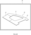
- FIG. 3A is a schematic diagram for explaining a manufacturing method of a structural member according to an embodiment, and is a diagram showing a blank according to an embodiment.
- FIG. 3B is a schematic diagram for explaining the manufacturing method of a structural member according to the embodiment, and is a diagram showing a blank according to the embodiment.
- FIG. 3C is a schematic diagram for explaining the manufacturing method of a structural member according to the embodiment, and shows a blank according to the embodiment.
- FIG. 3D is a schematic diagram for explaining the manufacturing method of a structural member according to the embodiment, and shows a blank according to the embodiment.
- FIG. 3A is a schematic diagram for explaining a manufacturing method of a structural member according to an embodiment, and is a diagram showing a blank according to an embodiment.
- FIG. 3B is a schematic diagram for explaining the manufacturing method of a
- FIG. 3E is a schematic diagram for explaining a manufacturing method of a structural member according to an embodiment.
- FIG. 3F is a schematic diagram for explaining the manufacturing method of the structural member according to the embodiment.
- FIG. 3G is a schematic diagram for explaining the manufacturing method of the structural member according to the embodiment.
- FIG. 4 is a cross-sectional view of a structural member manufactured by the manufacturing method according to the embodiment.
- FIG. 5 is a plan view of a structural member according to a modified example of the above embodiment.
- FIG. 6A is a diagram showing a division pattern of a structural member in the first embodiment.
- FIG. 6B is a diagram showing another division pattern of the structural member in the first embodiment.
- FIG. 6C is a diagram showing still another division pattern of the structural member in the first embodiment.
- FIG. 6D is a diagram showing still another division pattern of the structural member in the first embodiment.
- FIG. 6E is a diagram showing still another division pattern of the structural member in the first embodiment.
- FIG. 6F is a diagram showing yet another division pattern of the structural member in the first embodiment.
- FIG. 6G is a diagram showing yet another division pattern of the structural member in the first embodiment.
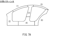
- FIG. 7A is a diagram showing a division pattern of a structural member in the second embodiment.
- FIG. 7B is a diagram showing another division pattern of the structural member in the second embodiment.
- FIG. 7C is a diagram showing yet another division pattern of the structural member in the second embodiment.
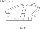
- FIG. 7D is a diagram showing still another division pattern of the structural member in the second embodiment.
- the blank for hot stamping includes a plurality of steel sheets.
- the plurality of steel sheets are arranged and joined to have a ring shape in a plan view of the blank.
- the plurality of steel sheets include a first steel sheet and a second steel sheet.
- the second steel sheet has an end portion.
- the end portion of the second steel sheet is overlapped and joined to the end portion of the first steel sheet to form an overlap portion together with the end portion of the first steel sheet.
- the steel sheet constituting the portion having the smallest sheet thickness in the blank is a plated steel sheet having a base steel sheet and a plating layer provided on the base steel sheet.
- the overlap portion has the largest sheet thickness in the blank.
- the emissivity of the surface located outside the overlap portion in each of the first steel sheet and the second steel sheet is greater than the emissivity of at least one of the other surfaces in the plurality of steel sheets (first configuration).
- the end of the first steel sheet and the end of the second steel sheet form an overlap portion having the maximum sheet thickness in the blank.
- the emissivity of the surface located outside the overlap portion in each of the first steel sheet and the second steel sheet is greater than the emissivity of at least one other surface in the blank. That is, in the blank, the emissivity of both outer surfaces of the overlap portion is relatively high.
- the heating of the blank required for hot stamping can be completed before the alloying of the plating layer in the steel sheet with the minimum sheet thickness, which has been heated in advance, progresses excessively and the diffusion layer becomes thick.
- the strength of the overlap portion with the maximum sheet thickness can be ensured by hot stamping, and the corrosion resistance (rust resistance) of the steel sheet with the minimum sheet thickness can be ensured.
- the blank according to the first configuration makes it possible to manufacture a structural component that combines the strength of the overlap portion having the greatest plate thickness with the rust prevention function of the portion having the smallest plate thickness.
- the blank can increase the heating rate of the overlap portion having the greatest plate thickness, and as a result, it becomes easier to ensure the process window of the heating conditions in the manufacture of the structural component.
- the heating time of the blank for hot stamping can be shortened, thereby improving the productivity of the structural component.
- by shortening the heating time of the blank energy consumption in the manufacture of the structural component is suppressed, and the amount of greenhouse gases generated when the blank is heated for hot stamping can be reduced.
- each of the multiple steel sheets may be a plated steel sheet.
- the plated steel sheet has a base steel sheet and a plating layer provided on the base steel sheet (second configuration).
- each steel sheet included in the blank is a plated steel sheet.
- the generation of oxide scale can be suppressed. Therefore, after hot stamping, there is no need to subject the structural component to a process for removing oxide scale, such as shot blasting. This makes it possible to increase the productivity of the structural component.
- the plating layer may be an aluminum-based plating layer (third configuration).
- each steel sheet is a plated steel sheet having an aluminum-based plating layer as in the third configuration
- a difference in the heating rate is likely to occur, particularly between the overlapping portion having the greatest sheet thickness and the steel sheet having the smallest sheet thickness.
- the aluminum-based plating layer is close to white, it is likely to reflect heat energy and inhibit the heating of the overlapping portion.
- the heating of the overlapping portion can be promoted when the blank is heated during hot stamping, and the heating time of the overlapping portion can be shortened. As a result, the corrosion resistance of the steel sheet with the smallest sheet thickness can be ensured, and the productivity of structural members manufactured from the blank can be improved.
- the surfaces of the first and second steel plates located outside the overlapping portion may be coated with a coating.
- This coating has, for example, an emissivity of 60% or more at a wavelength of 8.0 ⁇ m at 25°C (fourth configuration).
- the surfaces of the first and second steel plates located outside the overlapping portion may be covered with a coating.
- This coating may contain carbon black, one or more oxides selected from the group consisting of Zr oxide, Zn oxide, and Ti oxide, and 0 to 0.30 g/ m2 of silica.
- the carbon black and the oxide may be present in a dispersed state throughout the coating.
- XCB and XOxide satisfy the following formula (1) (see Patent Document 1) (fifth configuration). 118.9 ⁇ 24280/ ⁇ 6700/(100+76 ⁇ X CB )+18000/(130+65 ⁇ X Oxide ) ⁇ 332.0 (1)
- the plurality of steel plates may include two or more steel plates having different thicknesses.
- the thickness of the overlap portion is tmax and the thickness of the steel plate constituting the portion having the smallest thickness in the blank is tmin , it is preferable that tmax / tmin ⁇ 3.2 (sixth configuration).
- the difference in thickness between the overlap portion and the steel sheet constituting the portion having the smallest thickness in the blank becomes larger compared to when all the steel sheets included in the blank have the same thickness.
- the difference in thickness is excessive, when manufacturing a structural member from a blank by hot stamping, the temperature rise of the overlap portion becomes slower than that of the steel sheet constituting the portion having the smallest thickness in the blank, and it is easy to ensure the process window of the heating conditions. Therefore, in the sixth configuration, the ratio of the thickness t max of the overlap portion to the minimum thickness t min : t max /t min is set to 3.2 or less.
- the manufacturing method for a structural member according to the embodiment includes the steps of preparing a blank according to any one of the first to sixth configurations, heating the multiple steel plates contained in the blank to an austenite transformation completion temperature or higher, and using a die to form the heated blank into a structural member that is annular in plan view and quenching it (seventh configuration).
- a structural member includes a member body and a coating.
- the member body is formed by a plurality of steel plates joined together and has an annular shape in a plan view.
- the plurality of steel plates include a first steel plate and a second steel plate.
- the second steel plate has an end portion.
- the end portion of the second steel plate is overlapped and joined to the end portion of the first steel plate to form an overlap portion together with the end portion of the first steel plate.
- the coating is provided on a surface located outside the overlap portion of each of the first steel plate and the second steel plate.
- the coating contains 0.001 g/ m2 or more of one or more oxides selected from the group consisting of Zr oxide, Zn oxide, and Ti oxide (eighth configuration).
- a structural member includes a member body and a coating.
- the member body is formed by a plurality of steel plates joined together and has an annular shape in a plan view.
- the plurality of steel plates include a first steel plate and a second steel plate.
- the second steel plate has an end portion.
- the end portion of the second steel plate is overlapped and joined to the end portion of the first steel plate to form an overlap portion together with the end portion of the first steel plate.
- the coating is provided on a surface located outside the overlap portion of each of the first steel plate and the second steel plate.
- the coating contains 0.500 g/ m2 or less of carbon black (ninth configuration).
- the structural member may be a door ring part of an automobile.
- the member body may include a front pillar, a center pillar, and a rocker connecting the front pillar and the center pillar (tenth configuration).
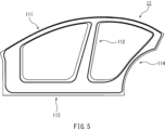
- [Structural Members] 1 is a diagram (plan view) of a structural member 10 according to the present embodiment, viewed from above in a state in which the structural member 10 is placed on a horizontal surface.
- the structural member 10 is used, for example, in the body of an automobile.
- the structural member 10 is typically a door ring part of an automobile. In the present embodiment, an example in which the structural member 10 is a door ring part will be described.
- the structural member 10 is a hot stamped member. That is, the structural member 10 is formed by hot stamping (hot press processing) a blank made of multiple steel plates.
- the structural member 10 includes a member body 11.
- the member body 11 has an annular shape in a plan view of the structural member 10.
- the member body 11 includes a front pillar 111, a center pillar 112, and a rocker 113.
- the center pillar 112 is disposed behind the front pillar 111.
- the center pillar 112 extends generally in the vertical direction of the vehicle body.
- the front pillar 111 extends toward the center pillar 112.
- the rocker 113 is disposed below the front pillar 111 and the center pillar 112.
- the rocker 113 connects the front pillar 111 and the center pillar 112.
- the member body 11 is formed from a plurality of steel plates 21, 22, and 23 joined together.
- the front pillar 111 is mainly composed of the steel plates 21 and 23.
- the center pillar 112 is mainly composed of the steel plate 22.
- the rocker 113 is composed of the steel plates 22 and 23.
- FIG. 2 is a cross-sectional view taken along line II-II of FIG. 1.
- FIG. 2 shows a cross-section of the structural member 10 cut along the thickness direction at the position of the steel plate 21.
- the steel plate 21 has an open cross-section.
- the steel plate 21 has, for example, a roughly hat-shaped shape in the cross-sectional view of the structural member 10. More specifically, the steel plate 21 includes a top plate 211, vertical walls 212 and 213, and flanges 214 and 215.
- the vertical wall 212 is disposed on the opposite side of the vertical wall 213 with respect to the top plate 211. In the cross-sectional view of the structural member 10, one end of the vertical walls 212 and 213 is connected by the top plate 211.
- the other end of the vertical walls 212 and 213 is connected to the flanges 214 and 215, respectively.
- the flanges 214 and 215 protrude from the vertical walls 212 and 213 to the outside of the structural member 10.
- the width W of the steel plate 21, i.e., the portion located above the front pillar 111 may be 15 mm or more and 300 mm or less.
- the height H of the steel plate 21, i.e., the portion located above the front pillar 111 may be 10 mm or more and 150 mm or less.
- the width W is the distance from the end of the R on the vertical wall 212 side of the corner portion between the top plate 211 and the vertical wall 212 to the end of the R on the vertical wall 213 side of the corner portion between the top plate 211 and the vertical wall 213 in the cross section of the structural member 10.
- the height H is the distance from the top plate 211 to the flanges 214, 215 along the plate thickness direction of the top plate 211.
- the other steel plates 22 and 23 have an open cross section like the steel plate 21.
- the steel plates 22 and 23 can also have, for example, a roughly hat-shaped cross section in the cross section of the structural member 10.
- the width of the part of the steel plate 22 that corresponds to the center pillar 112 (FIG. 1) may be 15 mm or more and 300 mm or less.
- the height of the part of the steel plate 22 that corresponds to the center pillar 112 may be 10 mm or more and 150 mm or less.
- the width of the part of the steel plate 23 that corresponds to the lower part of the front pillar 111 (FIG. 1) may be, for example, 30 mm or more and 750 mm or less.
- the height of the part of the steel plate 23 that corresponds to the lower part of the front pillar 111 may be 25 mm or more and 150 mm or less.
- the width of the part of the steel plate 23 that corresponds to the locker 113 (FIG. 1) may be, for example, 30 mm or more and 300 mm or less.
- the height of the part of the steel plate 23 that corresponds to the locker 113 may be 25 mm or more and 150 mm or less.
- the size of the structural member 10, which is annular in plan view, is, for example, 1.0 m or more.
- the size of the structural member 10 may be, for example, 4.0 m or less.
- the size of the structural member 10 is the length of the line segment connecting any two points on the outer periphery of the structural member 10 that are farthest apart when the structural member 10 is placed on a horizontal surface and viewed vertically.
- the method for manufacturing the structural member 10 includes the steps of preparing a blank 20, heating the blank 20, and forming the heated blank 20 into the structural member 10.
- a blank 20 having a shape obtained by developing the structural member 10 is prepared.
- the blank 20 includes a plurality of steel plates 21, 22, and 23.
- the steel plates 21, 22, and 23 are arranged and joined to have an annular shape in a plan view of the blank 20.
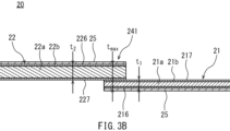
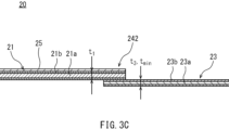
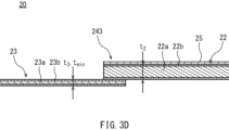
- FIGS. 3B, 3C, and 3D are cross-sectional views of blank 20 showing the joints of steel plates 21, 22, and 23.
- FIGS. 3B, 3C, and 3D are cross-sectional views taken along lines IIIB-IIIB, IIIC-IIIC, and IIID-IIID in FIG. 3A, respectively.
- steel plate 21 is overlap-joined to each of steel plates 22 and 23. That is, the end of steel plate 22 is overlap-joined to the end of steel plate 21, thereby forming overlap portion 241 together with the end of steel plate 21. Similarly, the end of steel plate 23 is overlap-joined to the end of steel plate 21, thereby forming overlap portion 242 together with the end of steel plate 21.
- steel plate 22 is overlap-joined to steel plate 23 in addition to steel plate 21.
- the end of steel plate 22 is overlapped and joined to the end of steel plate 23 to form an overlap portion 243 together with the end of steel plate 23.
- Steel plates 21, 22, and 23 are joined by, for example, spot welding or laser welding.
- the steel plate 21 has a plate thickness t1 .
- the steel plate 22 has a plate thickness t2 .
- the steel plate 23 has a plate thickness t3 .
- the plate thickness t1 of the steel plate 21 and the plate thickness t2 of the steel plate 22 are greater than the plate thickness t3 of the steel plate 23. Therefore, the overlap portion 241 of the steel plates 21 and 22 has a maximum plate thickness tmax in the blank 20.
- the plate thickness tmax of the overlap portion 241 is greater than the plate thickness of the overlap portion 242 of the steel plates 21 and 23 and the plate thickness of the overlap portion 243 of the steel plates 22 and 23.
- the steel plate 23 has the smallest plate thickness t3 among the multiple steel plates 21, 22, and 23 included in the blank 20. Therefore, the steel plate 23 constitutes a portion having the smallest plate thickness tmin in the blank 20. In other words, the portion of the steel plate 23 that is not overlapped with the other steel plates 21 and 22 is the portion having the smallest plate thickness tmin in the blank 20, and the plate thickness t3 of the steel plate 23 is the smallest plate thickness tmin in the blank 20.
- the ratio of the maximum plate thickness tmax and the minimum plate thickness tmin in the blank 20, tmax / tmin is greater than 2.0.
- the maximum plate thickness tmax and the minimum plate thickness tmin satisfy, for example , tmax / tmin ⁇ 4.0. It is preferable that the maximum plate thickness tmax and the minimum plate thickness tmin satisfy tmax / tmin ⁇ 3.2.
- the maximum plate thickness tmax and the minimum plate thickness tmin may be tmax / tmin ⁇ 2.5.
- the maximum plate thickness tmax is, for example, 4.2 mm or less.
- the plate thickness tmax may be 1.6 mm or more.
- the steel plates 21 and 22 form an overlap portion 241 having a maximum plate thickness t max in the blank 20.
- the emissivity of the surfaces 216 and 226 located outside the overlap portion 241 in each of the steel plates 21 and 22 is higher than the emissivity of at least one of the other surfaces of the steel plates 21, 22, and 23 included in the blank 20. That is, the emissivity of the surfaces 216 and 226 located outside the overlap portion 241 in the steel plates 21 and 22 is higher than the emissivity of the surfaces 217 and 227 located inside the overlap portion 241 in the steel plates 21 and 22 and/or the emissivity of one or both surfaces of the other steel plate 23.
- the surfaces 216 and 226 located outside the overlap portion 241 in each of the steel plates 21 and 22 are surfaces that constitute the front and back surfaces of the overlap portion 241 having the maximum plate thickness t max .
- the emissivity of the surfaces 216, 226 located outside the overlap portion 241 of the steel plates 21, 22 is greater than the emissivity of the surfaces 217, 227 located inside the overlap portion 241.
- the emissivity of the surfaces 216, 226 located outside the overlap portion 241 of the steel plates 21, 22 is greater than the emissivity of both surfaces of the steel plate 23 constituting the portion having the minimum plate thickness t min .
- the emissivity at a wavelength of 8.0 ⁇ m at 25° C. of the surfaces 216, 226 of the steel plates 21, 22 is more preferably 70% or more, and even more preferably 80% or more.
- the emissivity at a wavelength of 8.0 ⁇ m at 25° C. of at least one of the surfaces other than the surfaces 216, 226 of the steel plates 21, 22, 23 included in the blank 20 may be less than 60%.
- the emissivity can be measured in accordance with JIS R 1801 (2002). In this case, a sample taken from the steel plate to be measured is set in a Fourier transform infrared spectrophotometer, and the radiation intensity at a wavelength of 8.0 ⁇ m is measured at 25° C. to calculate the emissivity. Alternatively, it is also possible to measure the radiation intensity of a portion of interest at 25° C. using a radiation thermometer set to a measurement wavelength of 8.0 ⁇ m, and calculate the emissivity from the ratio to the radiation intensity of a black body.
- the entire surface 216 of the steel plate 21 opposite the steel plate 22 is covered with the coating 25. Also, the entire surface 226 of the steel plate 22 opposite the steel plate 21 is covered with the coating 25. On the other hand, the coating 25 is not provided on the steel plate 23. As a result, the emissivity of both outer surfaces of the overlap portion 241 is higher than the emissivity of the surface of the steel plate 23.
- the coating 25 is, for example, a black coating.
- the coating 25 may be a carbon-based surface treatment coating (a coating containing carbon (C)).
- a coating containing carbon (C) For example, when the lightness L * value (CIE 1976 lightness index L * defined in JIS Z8781-4 (2013)) from the surface of the coating 25 is 60 or less, the coating 25 can be determined to be black.
- the emissivity of the coating 25 at a wavelength of 8.0 ⁇ m at 25 ° C. is 60% or more, preferably 70% or more, and more preferably 80% or more. That is, the emissivity of the surfaces 216, 226 of the steel plates 21, 22 to which the coating 25 is applied at a wavelength of 8.0 ⁇ m at 25 ° C.
- the coating 25 is 60% or more, preferably 70% or more, and more preferably 80% or more.
- the coating 25 may have an emissivity of 60% or more at a wavelength of 8.0 ⁇ m at 700 ° C.
- a surface treatment coating described in Patent Document 1 can be used.
- the coating 25 may contain carbon black and one or more oxides selected from the group consisting of Zr oxide, Zn oxide, and Ti oxide.
- the coating 25 may or may not contain silica. That is, the silica content of the coating 25 is 0 g/ m2 or more.
- the silica content of the coating 25 may be 0.30 g/m2 or less .
- the silica content is more preferably 0.10 g/m2 or less, and even more preferably 0.05 g/m2 or less .
- the carbon black and the oxides can be present dispersedly throughout a surface of the coating 25 perpendicular to the thickness direction of the steel sheet 21.
- the carbon black content is X CB (g/m 2 )
- the content of one or more oxides (metal oxides) selected from the group consisting of Zr oxide, Zn oxide, and Ti oxide is X Oxide (g/m 2 )
- X CB and X Oxide preferably satisfy the following formula (1): 118.9 ⁇ 24280/ ⁇ 6700/(100+76 ⁇ X CB )+18000/(130+65 ⁇ X Oxide ) ⁇ 332.0 (1)
- the value calculated by the central formula: 24280/ ⁇ 6700/(100+76 ⁇ XCB )+18000/(130+65 ⁇ XOxide ) ⁇ is preferably 119.0 or more, more preferably 170.0 or more, and even more preferably 220.0 or more.
- the value calculated by the central formula is preferably 330.0 or less, more preferably 310.0 or less, and even more preferably 300.0 or less.
- the dispersion state of the carbon black and the metal oxide in the coating 25 can be confirmed by performing a surface analysis of the coating 25 for elements derived from the carbon black (e.g., C) and elements derived from the oxide (Zr, Zn, and Ti) using an electron probe microanalyzer (EPMA).
- the carbon black content X CB can be measured by a cross-sectional analysis of the coating 25 using a transmission electron microscope (TEM). That is, a cross-sectional analysis of the coating 25 is performed by TEM-EDS analysis on an area of a predetermined size (thickness of the coating 25 ⁇ 5 ⁇ m), and the thickness of the coating 25 and the area ratio of particles having a carbon content of 70 mass% or more in the area are measured.
- TEM transmission electron microscope
- the oxide content X Oxide can be obtained by performing elemental analysis on the surface of the coating 25 using an X-ray fluorescence analyzer (ZSX Primus, manufactured by RIGAKU Corporation) and quantifying the amounts of metallic Zr, metallic Zn, and metallic Ti.
- the carbon black content X CB in the coating 25 is preferably 0.030 g/m 2 or more, and more preferably 0.100 g/m 2 or more.
- the carbon black content X CB may be set within a range that satisfies formula (1), and is preferably 0.800 g/m 2 or less, and more preferably 0.600 g/m 2 or less.
- the coating 25 can contain 5.0% or more of carbon black by volume, and preferably contains 8.0% or more of carbon black by volume.
- the coating 25 can also contain 40.0% or less of carbon black by volume, and preferably contains 30.0% or less of carbon black by volume.
- the content X Oxide of the metal oxide in the coating 25 is preferably 0.030 g/m 2 or more, and more preferably 0.060 g/m 2 or more.
- the content X Oxide may be set within a range that satisfies the formula (1), and is preferably 0.500 g/m 2 or less, and more preferably 0.300 g/m 2 or less.
- the coating 25 can contain 1.0 or more volume percent of metal oxide.
- the coating 25 can also contain 30.0 or less volume percent of metal oxide, and preferably contains 25.0 or less volume percent of metal oxide.
- the ratio of the carbon black content XCB (g/ m2 ) to the metal oxide content XOxide (g/ m2 ): XOxide / XCB is preferably 0.20 or more and 200.00 or less, more preferably 0.40 or more and 10.00 or less , and further preferably 0.60 or more and 5.00 or less .
- the coating 25 may contain various binder components and additives in addition to the carbon black and metal oxides described above.
- the binder component is preferably a water-dispersible or water-soluble resin.
- the content of the binder component is preferably 40% by volume or more with respect to the total volume of the film 25.
- the binder component selected from the water-dispersible or water-soluble resins various known resins exhibiting water dispersibility or water solubility can be used. Examples of such resins exhibiting water dispersibility or water solubility include polyurethane resins, polyester resins, acrylic resins, epoxy resins, fluororesins, polyamide resins, polyolefin resins, and polymer compounds obtained by hydrolysis and condensation polymerization of silane coupling agents.
- the binder component is one or more selected from the group consisting of polyester resins, polyurethane resins, polyolefin resins, acrylic resins, epoxy resins, fluororesins, and polyamide resins.
- the polyurethane resin is preferably a polyether-based polyurethane resin.
- the additives include, for example, a leveling agent, a water-soluble solvent, a metal stabilizer, and an etching inhibitor.
- the leveling agent is, for example, a nonionic or cationic surfactant.
- nonionic or cationic surfactants include polyethylene oxide or polypropylene oxide adducts, and acetylene glycol compounds.
- water-soluble solvents examples include alcohols such as ethanol, isopropyl alcohol, t-butyl alcohol, and propylene glycol, cellosolves such as ethylene glycol monobutyl ether and ethylene glycol monoethyl ether, esters such as ethyl acetate and butyl acetate, and ketones such as acetone, methyl ethyl ketone, and methyl isobutyl ketone.
- metal stabilizers include chelate compounds such as EDTA (ethylenediaminetetraacetic acid) and DTPA (diethylenetriaminepentaacetic acid).
- etching inhibitors include amine compounds such as ethylenediamine, triethylenepentamine, guanidine, and pyrimidine.
- the coating 25 can be formed by applying an organic or inorganic treatment liquid containing, for example, carbon black and a metal oxide to the entire surfaces 216, 226 of the steel sheets 21, 22, and then drying the volatile components in the treatment liquid.
- the treatment liquid can be applied to the surfaces 216, 226 of the steel sheets 21, 22, for example, by a roll coater, a curtain coater, or an inkjet.
- the thickness of the coating 25 can be changed continuously.
- the thickness of the coating 25 is, for example, 0.5 ⁇ m or more and 5.0 ⁇ m or less.
- the thickness of the coating 25 is preferably 1.0 ⁇ m or more and 3.0 ⁇ m or less.
- the thickness of the coating 25 is negligibly small compared to the sheet thicknesses t 1 , t 2 of the steel sheets 21, 22. Therefore, the sheet thicknesses of the steel sheets 21, 22 measured including the coating 25 can be treated as the sheet thicknesses t 1 , t 2, respectively.
- the steel sheet 23 having the minimum sheet thickness t min in the blank 20 is a plated steel sheet.
- the steel sheet 23 has a base steel sheet 23a and a plated layer 23b.
- the type of the base steel sheet 23a is not particularly limited.
- the plated layer 23b is provided on the base steel sheet 23a.
- the plated layer 23b covers the entire or almost the entire both sides of the base steel sheet 23a.
- the plated layer 23b is a metal plated layer.
- the plated layer 23b may be, for example, hot-dip aluminum plating, hot-dip galvanizing, alloyed hot-dip galvanizing, or electrolytic galvanizing.
- As the steel sheet 23, a known aluminum-plated steel sheet, zinc-plated steel sheet, or the like can be used.
- the sheet thickness t min of the steel sheet 23 is the combined sheet thickness of the base steel sheet 23a and the plated layer 23b.
- the steel sheets 21 and 22 may be known plated steel sheets, similar to the steel sheet 23. That is, the steel sheet 21 may have a base steel sheet 21a and a plated layer 21b provided on the base steel sheet 21a.
- the steel sheet 22 may have a base steel sheet 22a and a plated layer 22b provided on the base steel sheet 22a.
- the type of the base steel sheets 21a and 22a is not particularly limited.
- the plated layers 21b and 22b cover the entire or almost the entire surfaces of the base steel sheets 21a and 22a, respectively.
- the plated layers 21b and 22b are metal plated layers. As the plated layers 21b and 22b, the same plated layers as those exemplified for the steel sheet 23 may be used.
- the steel sheets 21 and 22 may be aluminum plated steel sheets or zinc plated steel sheets, similar to the steel sheet 23.
- the sheet thickness t1 of the steel sheet 21 is the combined sheet thickness of the base steel sheet 21a and the plated layer 21b.
- the sheet thickness t2 of the steel sheet 22 is the combined sheet thickness of the base steel sheet 22a and the plated layer 22b.
- the plating layers 21b, 22b, and 23b are typically plating layers whose main component is aluminum (aluminum-based plating layers).
- the composition of the aluminum-based plating layers is not particularly limited. Known aluminum-based plating layers can be used as the plating layers 21b, 22b, and 23b.
- Steel sheets 21, 22, and 23 may each be a plated steel sheet of the same type as the other steel sheets, or a plated steel sheet of a different type from the other steel sheets.
- Steel sheets 21 and 22 may be steel sheets (bare materials) that do not have plating layers 21b and 22b on their surfaces.
- the coating weight of each steel sheet may be the same as or different from the other steel sheets.
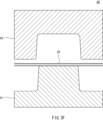
- the prepared blank 20 is formed into the structural member 10 (FIGS. 1 and 2) by hot stamping. During the hot stamping, the blank 20 is subjected to a heating step. Referring to FIG. 3E, in the heating step, the blank 20 is heated, for example, by a heating furnace 30.
- the multiple steel plates 21, 22, and 23 included in the blank 20 are heated to an austenite transformation completion temperature (A c3 point) or higher.
- the steel plates 21, 22, and 23 are heated, for example, to 900° C. or higher.
- the microstructures of the steel plates 21, 22, and 23 are transformed, for example, entirely or almost entirely into the austenite phase.
- the heated blank 20 is formed into an annular structural member 10 (Figs. 1 and 2) in a plan view using a die 40 and quenched.
- the blank 20 heated in the heating process is removed from the heating furnace 30 (Fig. 3E) and transported to the die 40.
- the die 40 is attached to a known press device.
- the die 40 includes, for example, a punch 41 and a die 42.
- the blank 20 is disposed between the punch 41 and the die 42.
- the die 42 approaches relatively to the punch 41.
- the blank 20 is clamped (pressed) by the punch 41 and the die 42 and formed into a shape that conforms to the forming surfaces of the punch 41 and the die 42.
- the blank 20 remains clamped between the punch 41 and the die 42.
- the blank 20 is cooled (quenched) by the die 40 and its microstructure is transformed into martensite. This allows the structural member 10 to be manufactured from the blank 20.
- FIG. 4 is a cross-sectional view of the structural member 10 after hot stamping.
- FIG. 4 shows a cross-section of the structural member 10 at the position of the steel plate 21 (FIGS. 3B and 3C) to which the black coating 25 was applied at the stage of the blank 20.
- This structural member 10 includes a member body 11 and a coating 12.
- the coating 12 is provided on the steel plate 21.
- the black coating 25 (FIGS. 3B and 3C) applied to the steel plate 21 in the blank 20 becomes the coating 12 through hot stamping.
- the black coating 25 (FIGS. 3B and 3D) applied to the steel plate 22 in the blank 20 becomes the coating 12 through hot stamping.
- the coating 12 is provided on the surfaces 216, 226 (FIG.
- the coating 25 before hot stamping contains carbon black, the carbon black is almost completely removed by high-temperature heating during hot stamping, but may remain on the member body 11. If the coating 25 before hot stamping satisfies the above formula (1), the coating 12 after hot stamping may not contain carbon black or may contain 0.500 g/m 2 or less of carbon black. If the coating 12 after hot stamping contains carbon black, the content of carbon black in the coating 12 is more than 0 g/m 2.
- the value calculated by the central formula: 24280/ ⁇ 6700/(100+76 ⁇ X CB )+18000/(130+65 ⁇ X Oxide ) ⁇ in the coating 12 after hot stamping is, for example, 120.0 or more and 150.0 or less.
- the coating 12 after hot stamping contains, for example, more than 0 g/m 2, more preferably 0.001 g/m 2 or more of one or more oxides (metal oxides) selected from the group consisting of Zr oxide, Zn oxide, and Ti oxide.
- the content of the metal oxide in the coating 12 is, for example, 0.500 g/m 2 or less .
- the coating 12 after hot stamping contains 0 to 0.30 g/m 2 of silica.
- the carbon black content, metal oxide content, and silica content in the coating 12 can be measured in the same manner as the coating 25 at the blank 20 stage.
- the vehicle body part is disassembled to obtain the ring-shaped structural member 10, and an analysis sample is obtained from this structural member 10, for example, by laser cutting.
- an analysis sample is obtained from each of the multiple steel plates included in the structural member 10.
- the analysis sample is obtained from the center or its vicinity of the top plate of each steel plate having an open cross section.
- the obtained analysis sample is adjusted by polishing the cross section to the outside of the heat-affected zone during laser cutting, etc., to prepare a sample for coating analysis.
- the dispersion state of carbon black and metal oxide in the coating 12 can be confirmed. Since the coating 12 is present on the front side and/or back side of the structural member 10 depending on the part of the structural member 10, the front side and back side of the analysis sample are analyzed.
- the outermost layer of the structural member 10 is, for example, an electrodeposition coating film.
- the coating layer that is present below the electrodeposition coating film layer and above the alloyed metal plating layer is analyzed.
- the carbon black content XCB in the coating 12 can be measured by a cross-sectional analysis of the coating 25 using a TEM. That is, a cross-sectional analysis of the coating 12 is performed by TEM-EDS analysis for an area of a predetermined size (thickness of the coating 12 ⁇ 5 ⁇ m), and the thickness of the coating 12 and the area ratio of particles having a carbon content of 70 mass% or more in the area are measured.
- the oxide content X Oxide can be determined by performing elemental analysis of the coating layer that is present under the electrodeposition coating layer and over the alloyed metal plating layer using the above-mentioned X-ray fluorescence analyzer, and quantifying the amounts of metal Zr, metal Zn, and metal Ti.
- steel plate 21 can have a tensile strength of, for example, 0.5 GPa or more, and preferably has a tensile strength of 1.0 GPa or more.
- steel plates 22 and 23 (FIG. 1) can have a tensile strength of, for example, 0.5 GPa or more, and preferably has a tensile strength of 1.0 GPa or more.
- At least one of steel plates 21, 22, and 23 may have a tensile strength of 1.5 GPa or more after the forming process.
- the tensile strength of each of steel plates 21, 22, and 23 may be the same as or different from the tensile strength of the other steel plates.
- the thickness of the diffusion layer is suppressed to a predetermined value or less.
- the thickness of the diffusion layer is preferably 15 ⁇ m or less.
- the thickness of the diffusion layer is preferably 10 ⁇ m or less. Therefore, in the blank 20 according to the present embodiment, the emissivity of the surfaces 216, 226 of the steel sheets 21, 22 located outside the overlap portion 241 having the maximum sheet thickness t max is greater than the emissivity of at least one of the other surfaces of the steel sheets 21, 22, 23. That is, the surfaces 216, 217 on both outer sides of the overlap portion 241 in the steel sheets 21, 22 are treated to increase the emissivity.
- the heating rate of the overlap portion 241 can be increased, and the heating time of the overlap portion 241 can be shortened. Therefore, the heating of the blank 20 can be terminated before the alloying of the plating layer 23b in the thinnest steel sheet 23, which has been heated first, progresses excessively and the diffusion layer grows to exceed a predetermined thickness.
- the strength of the overlap portion 241 having the maximum sheet thickness t max can be ensured by hot stamping, and the corrosion resistance (rust resistance) of the steel sheet 23 having the minimum sheet thickness t min can be ensured. Furthermore, by suppressing the thickness of the diffusion layer, the weldability of the steel plate 23 is more easily ensured.
- the heating rate of the overlap portion 241 having the maximum sheet thickness t max can be increased. Therefore, it is possible to heat the entire blank 20 to a temperature required for hot stamping before the alloying of the plating layer 23b in the thinnest steel sheet 23 progresses excessively, and the process window of the heating conditions in the manufacture of the structural member 10 can be secured. Therefore, it is possible to manufacture a structural member 10 that has both the strength of the overlap portion 241 having the maximum sheet thickness t max and the rust prevention function at the position of the steel sheet 23 having the minimum sheet thickness t min .
- the heating time of the blank 20 can be shortened, and the productivity of the structural member 10 can be improved. Furthermore, by shortening the heating time of the blank 20, the energy consumption in the manufacture of the structural member 10 can be suppressed, and the amount of greenhouse gas generated during heating can be reduced.
- the steel sheets 21, 22, and 23 included in the blank 20 may all be plated steel sheets.
- the generation of oxide scale can be suppressed. Therefore, after hot stamping, it is not necessary to subject the structural member 10 to a process for removing oxide scale, such as a shot blasting process. This makes it possible to increase the productivity of the structural member 10.
- the plating layers 21b, 22b, and 23b of the steel sheets 21, 22, and 23 are aluminum-based plating layers
- a difference in temperature rise rate is likely to occur between the overlap portion 241 having the maximum sheet thickness t max and the steel sheet 23 having the minimum sheet thickness t min in the heating process.
- the aluminum-based plating layer is white, it is likely to reflect heat energy and inhibit the temperature rise of the overlap portion 241.
- the surfaces 216 and 226 of the steel sheets 21 and 22 arranged on both outer sides of the overlap portion 241 are treated to increase the emissivity.
- the steel sheets 21 and 22 forming the overlap portion 241 are plated steel sheets having aluminum-based plating layers, the temperature rise of the overlap portion 241 in the heating process can be promoted and the heating time of the overlap portion 241 can be shortened. Therefore, the corrosion resistance and weldability of the thin steel sheet 23 can be ensured, and the productivity of the structural member 10 can be improved.
- the steel plate 23 having the smallest thickness t min in the blank 20 first reaches the temperature in the austenite region, and then the thinner portions reach the temperature in the austenite region in order.
- the overlap portion 241 having the largest thickness t max reaches the temperature in the austenite region last.
- the minimum thickness t min and the maximum thickness t max are too far apart, the temperature rise of the overlap portion 241 having the thickness t max is significantly delayed compared to the steel plate 23 having the thickness t min , and the process window of the heating conditions may not be secured.
- the ratio of the minimum thickness t min to the maximum thickness t max : t max /t min is 3.2 or less.
- a coating 25 can be applied to the surfaces 216, 226 of the steel plates 21, 22 opposite the mating steel plate.
- the emissivity of the coating 25 is, for example, 60% or more. This allows the overlap portion 241 to be efficiently radiated and makes it easier to increase the temperature rise rate of the overlap portion 241 during the heating process.
- the coating 25 may contain carbon black, one or more oxides selected from the group consisting of Zr oxide, Zn oxide, and Ti oxide, and 0 to 0.30 g/m2 or less of silica.
- the carbon black content XCB (g/ m2 ) and the oxide content XOxide (g/ m2 ) preferably satisfy the above formula (1).
- formula (1) specifies the relationship between the rate of increase (%) of the temperature rise rate (°C/s), the carbon black content XCB, and the oxide content XOxide .
- Formula (1) indicates that carbon black mainly functions as a heat absorbing material in the range up to 700°C, and oxide mainly functions as a heat absorbing material in the range of 700°C or more.
- the emissivity at 25° C. and a wavelength of 8.0 ⁇ m for both outer surfaces 216 , 226 of overlap portion 241 to which coating 25 is applied tends to be 60% or more.
- the carbon black and oxides can be dispersed throughout the entire surface of the coating 25 that is perpendicular to the thickness direction of the steel plate 21. This makes it easier to homogenize the emissivity of the surfaces 216, 226 of the steel plates 21, 22 located on both outsides of the overlap portion 241. Therefore, the thickest overlap portion 241 can be heated quickly and uniformly during the heating process.
- the coating 25 may be a substantially black coating in order to increase the emissivity of both outer surfaces 216, 226 of the overlapping portion 241 compared to an untreated case.
- the coating 25 may contain graphite or soot instead of or in addition to carbon black.
- the coating 25 may contain, for example, an acicular compound having a hexagonal crystal structure with an aspect ratio of 4 to 50 inclusive in order to increase the emissivity of both outer surfaces 216, 226 of the overlapping portion 241.
- the compound having a hexagonal crystal structure is typically graphite (C), but may also be lanthanum silicate, magnesium diboride, beryllium oxide (beryllia), zinc oxide, ⁇ -quartz, goethite (NiS), wurtzite (ZnS), or the like.
- the emissivity of both surfaces of the steel plate 23 having the minimum plate thickness t min is smaller than the emissivity of the surfaces 216, 226 located outside the overlap portion 241 in each of the steel plates 21, 22. That is, the steel plate 23 is not provided with a coating 25 such as the overlap portion 241.
- the emissivity of at least one surface of the steel plate 23 having the minimum plate thickness t min may be substantially equal to the emissivity of the surfaces 216, 226 on both outer sides of the overlap portion 241.
- one or both sides of the steel plate 23 may be covered with a coating 25 similar to that of the overlap portion 241.
- the black coating 25 is not provided on at least one surface of the steel plate 23. That is, it is preferable that the emissivity of the surfaces 216, 226 located outside the overlap portion 241 in each of the steel plates 21, 22 is larger than the emissivity of at least one surface of the steel plate 23 having the minimum plate thickness t min .
- the emissivity of the surfaces 217 and 227 located inside the overlap portion 241 is smaller than the emissivity of the surfaces 216 and 226 located outside the overlap portion 241. That is, in the steel plates 21 and 22, the surfaces 217 and 227 located inside the overlap portion 241 are not provided with the coating 25. However, in the steel plate 21, the surface 217 located inside the overlap portion 241 may be covered with the coating 25. Similarly, in the steel plate 22, the surface 227 located inside the overlap portion 241 may be covered with the coating 25.
- the outer surfaces 216 and 226 of the overlap portion 241 are substantially covered with the black coating 25, and the surfaces 217 and 227 located inside the overlap portion 241 are not covered with the coating 25.
- both surfaces 216, 217 of the steel plate 21 are covered with the coating 25, the heating of the portion of the steel plate 21 that is not overlapped with the steel plate 22 progresses, the diffusion layer becomes thick, and it may be difficult to ensure the corrosion resistance and weldability of the steel plate 21.
- both surfaces 226, 227 of the steel plate 22 are covered with the coating 25, the heating of the portion of the steel plate 22 that is not overlapped with the steel plate 21 progresses, the diffusion layer becomes thick, and the corrosion resistance and weldability of the steel plate 22 may be reduced. Therefore, in order to more easily ensure good corrosion resistance and weldability, it is preferable that the coating 25 is provided on the surfaces 216, 226 located outside the overlap portion 241 of the steel plates 21, 22, while the coating 25 is not provided on the surfaces 217, 227 located inside the overlap portion 241.
- the presence of the substantially black coating 25 increases the emissivity of both outer surfaces 216, 226 of the overlap portion 241 having the maximum sheet thickness t max compared to the emissivity of one or more other surfaces of the steel sheets 21, 22, 23.
- the method of increasing the emissivity of a selected portion of the blank 20 is not limited to the coating 25.
- the emissivity of the selected portion can be increased more than that of the other portions by increasing the surface roughness of the selected portion compared to the surface roughness of the other portions.
- the steel plates 21, 22, and 23 included in the blank 20 may each be a single layer or multiple layers. That is, the steel plates 21, 22, and 23 may each be a single steel plate, or a plate material formed by stacking multiple steel plates.
- the ends of the steel plates 21, 22 are overlapped and joined to each other to form an overlap portion 241.
- the ends of the steel plates 21, 23 are overlapped and joined to each other to form an overlap portion 242.
- the ends of the steel plates 22, 23 are overlapped and joined to each other to form an overlap portion 243.
- the blank 20 includes at least one overlap portion.
- the steel plate 23 does not necessarily have to be overlapped and joined to the steel plates 21, 22.
- the steel plate 23 may be butt-joined to one or both of the steel plates 21, 22.
- the blank 20 includes three steel plates 21, 22, and 23.
- the blank 20 may be composed of two steel plates, or may include four or more steel plates.
- the blank 20, which is annular in plan view, typically includes three or more steel plates.
- the steel plates 21 and 22 forming the overlap portion 241 having the maximum plate thickness t max are treated to increase the emissivity on the surfaces 216 and 226 located outside the overlap portion 241.
- the other steel plates may or may not be treated to increase the emissivity.
- the blank 20 may include one or more steel plates that are not treated to increase the emissivity on one or both sides.
- the steel plates 21 and 22 different from the steel plate 23 constituting the portion having the minimum plate thickness t min form the overlap portion 241 having the maximum plate thickness t max .
- the steel plate 21 or the steel plate 22 forming the overlap portion 241 may be the steel plate having the minimum plate thickness t min in the blank 20.
- the steel plates 21, 22, and 23 have different thicknesses.
- two or more of the steel plates included in the blank 20 may have the same thickness, or all of the steel plates may have the same thickness.
- the portion of each steel plate that does not form an overlap portion in the blank 20 has the minimum thickness t min , and each overlap portion has the maximum thickness t max .
- the emissivity of both outer surfaces of the overlap portion with the maximum thickness t max is greater than the emissivity of at least one of the other surfaces.
- t max /t min is 2.0.
- the die 40 used for hot stamping the blank 20 includes a punch 41 and a die 42.
- the configuration of the die 40 is not limited to the example described in the above embodiment.
- the die 40 can further include, for example, a pad and a blank holder.
- the main body 11 of the structural member 10 includes a front pillar 111, a center pillar 112, and a rocker 113.
- the member main body 11 can further include other components.
- the member main body 11 can further include a rear pillar 114.
- the structural member 10 according to the above embodiment is a door ring part having a single ring shape (single door ring part).
- the structural member shown in FIG. 5 is a door ring part having a double ring shape (double door ring part).
- the blank that serves as the material also has a double ring shape.
- the material type is listed in the following order: plating type, tensile strength, and application (hot stamping).
- the black coating is a black coating that contains carbon black and metal oxides.
- Black coating - one side means that one entire side of the steel sheet is covered with a black coating.
- Black coating - both sides means that both entire sides of the steel sheet are covered with a black coating.
- Figures 6A to 6G show the division pattern of the structural members.
- Figures 6A to 6G show the number of steel plates (materials) contained in the structural members that are single door ring parts, and the positions of the joints between the steel plates in the structural members.
- each steel plate is given a number in parentheses.
- the structural member is formed from three pieces of material (1) to (3). Each of materials (1) to (3) is overlapped and joined with the adjacent material.
- 910°C arrival time refers to the time required for the material having the minimum sheet thickness t min among the materials contained in the blank to reach 910°C (A c3 point or more) from the start of heating the blank.
- Heating completion time refers to the time required for the part of the blank with the slowest temperature rise to reach 910°C from the start of heating the blank and become hot stampable.
- Process window (PW) refers to the value obtained by subtracting the heating completion time from the time obtained by adding the allowable heating time (245 seconds) after the material having the minimum sheet thickness t min reaches 910°C to the time to reach 910°C. The larger this value, the wider the process window of the heating conditions in hot stamping of structural members.
- Comparative Example 1 which has the same combination of material type and thickness as Example 1, a black coating is not applied to any of the materials (1) to (3).
- Example 1 a black coating is arranged on both outsides of the thickest overlap portion, which promotes the temperature rise of the overlap portion, and the heating completion time of the blank is significantly shortened compared to Comparative Example 1.
- Example 1 although the time to reach 910° C. was shorter than in Comparative Example 1 due to the black coating applied to the thinnest material (3), the process window was extended by nearly 60 seconds compared to Comparative Example 1.
- Comparative Example 2 which has the same combination of material type and thickness as Example 3, a black coating is not applied to any of the materials (1) to (3).
- Example 3 a black coating is arranged on both outsides of the thickest overlap portion, which promotes the temperature rise of the overlap portion, and the heating completion time of the blank is significantly shortened compared to Comparative Example 2.
- the thinnest material (2) was provided with a black coating, the time to reach 910°C was shorter than in Comparative Example 2, but the process window was extended by 70 seconds or more compared to Comparative Example 2.
- the process window of the heating conditions was eliminated (negative).
- the structural member is formed from four pieces of material (1) to (4). Each of materials (1) to (4) is overlapped and joined with the adjacent material.
- Example 4 to 10 in Table 3 similarly to Examples 1 to 3 (Table 2), black coatings are disposed on both outer surfaces of the overlapping portion having at least the maximum plate thickness t max . Therefore, the process window of the heating conditions was sufficiently secured in Examples 4 to 10. When each Example is compared with the corresponding Comparative Example, it is found that the process window is expanded.
- Comparative Example 4 the combination of material type and sheet thickness is the same as in Example 8, but a black coating is not applied to any of the materials, including the overlap portion.
- the temperature rise of the overlap portion is promoted, and the heating completion time of the blank is significantly shortened compared to Comparative Example 4.
- the process window is expanded by more than 100 seconds compared to Comparative Example 4.
- Comparative Example 4 the process window of the heating conditions is eliminated (negative).
- Comparative Example 7 the combination of material type and sheet thickness is the same as in Example 9, but the materials (1) and (3) forming the overlap portion are not provided with a black coating.
- the temperature rise of the overlap portion is promoted, and the blank heating completion time is significantly shortened compared to Comparative Example 7.
- the process window is expanded by 80 seconds or more compared to Comparative Example 7.
- Comparative Example 7 the black coating is applied to both sides of the thinnest material (4), and the 910 ° C. arrival time was slightly more than 10 seconds earlier than in Example 9, but in Example 9, the blank heating completion time is shortened by 70 seconds or more compared to Comparative Example 7, so it can be said that the process window is expanded compared to Comparative Example 7 even when the difference in the 910 ° C. arrival time is taken into account.
- Table 4 shows the analysis conditions and results for division patterns 5 and 6 shown in Figures 6E and 6F.
- the structural member is formed from five pieces of material (1) to (5). Each of the materials (1) to (5) is overlapped and joined with the adjacent material.
- Examples 11 to 16 in Table 4 similar to Examples 1 to 10 (Tables 2 and 3), black coatings are provided on both outer surfaces of the overlapping portion having at least the maximum plate thickness t max . Therefore, the process window of the heating conditions was sufficiently secured in Examples 11 to 16. When each Example is compared with the corresponding Comparative Example, it is found that the process window is expanded.
- Comparative Example 9 the combination of material type and sheet thickness is the same as in Example 13, but a black coating is not applied to any of the materials, including the overlap portion.
- the temperature rise of the overlap portion is promoted, and the heating completion time of the blank is significantly shortened compared to Comparative Example 9.
- the process window is expanded by more than 90 seconds compared to Comparative Example 9.
- Comparative Example 9 the process window of the heating conditions is eliminated (negative).
- Comparative Example 11 the combination of material type and plate thickness is the same as in Example 15, but a black coating is not applied to any of the materials, including the overlap portion.
- the temperature rise of the overlap portion was promoted, and the heating completion time of the blank was significantly shortened compared to Comparative Example 11.
- the process window was expanded by more than 60 seconds compared to Comparative Example 11.
- the steel plates used as materials were selected from those shown in Table 1.
- the division pattern of the structural members is as shown in Figures 7A to 7D.
- Figures 7A to 7D show the number of steel plates (materials) contained in the structural members that are double door ring parts, and the positions of the joints between the steel plates in the structural members.
- each steel plate used as material is given a number in parentheses.
- Table 5 shows the analysis conditions and results for division patterns 8 and 9 shown in Figures 7A and 7B.
- the structural member is formed from six pieces of material (1) to (6). Each of the materials (1) to (6) is overlapped and joined with the adjacent material.
- a black coating is applied to any of materials (1) to (6) including the overlapping portions.
- the structural member is formed from seven pieces of material (1) to (7). Each of the materials (1) to (7) is overlapped and joined with the adjacent material.
- a black coating is applied to any of materials (1) to (7), including the overlapping portions.
- the division patterns of Test Examples 1 and 3 are division patterns 7 shown in FIG. 6G.
- the division patterns of Test Example 2 and the Reference Example are division patterns 5 shown in FIG. 6E.
- each material forms an overlap portion at the joint with the other material.
- a black coating is applied to both outer surfaces of the overlap portion having the maximum plate thickness t max .
- each of the materials (1) to (5) has a plate thickness difference with one or more other materials.
- the materials (1) to (5) all have the same plate thickness.
- a black coating is not applied to any of the materials (1) to (5), including the overlap portion.
- the ratio of the maximum thickness t max (thickness of the overlapping portion) to the minimum thickness t min (thickness of the materials (1) to (5)): t max /t min is 2.0.
- the difference (t max /t min ) between the maximum thickness t max and the minimum thickness t min is not large, it is possible to secure a certain process window of the heating conditions without increasing the emissivity of both outer surfaces of the overlapping portion.
- the difference (t max /t min ) between the maximum thickness t max and the minimum thickness t min exceeds 2.0. In this case, the effect of increasing the emissivity of both outer surfaces of the overlapping portion (applying a black coating) is likely to be significantly manifested.
- test examples 1 to 3 the productivity of the structural members and the greenhouse gas emissions ratio were evaluated. In addition, for test examples 1 to 3, the rust prevention performance of the structural members was evaluated. The evaluation results are shown in Table 8.
- the amount of greenhouse gases generated in the heating process was calculated by setting the power consumption of the multi-stage electric heating furnace for hot stamp blank heating at 450 kWh per hour, the furnace temperature at 920 °C, the daily operating time at 15 hours, and the heating and waiting time in the heating furnace at 3 hours, assuming the production of parts with the productivity shown in Table 8, allocating it to the power consumption per structural part, and multiplying it by the greenhouse gas intensity per kWh of the average electricity in Japan in 2018 (from the LCA database AIST IDEAv3.2).
- Test Examples 1 and 2 the blank heating completion time was shorter than in Test Example 3, so that the alloying of the thinnest plating layer of the material did not progress excessively during blank heating, and the deterioration of the rust prevention performance (corrosion resistance) of the material was suppressed.
- Test Examples 1 and 2 were able to maintain high rust prevention performance compared to Test Example 3.
- the rust prevention performance was evaluated by cutting out corrosion evaluation test pieces (evaluation samples) from the overlapping part and other parts of the hot stamped structural member, adopting cycle conditions close to the actual environment specified in the accelerated corrosion test method (VDA233-102) of the German Association of the Automotive Industry (VDA), and conducting a combined cycle test (CCT).
- VDA233-102 accelerated corrosion test method
- VDA German Association of the Automotive Industry
- CCT combined cycle test
- Test Example 3 was rated low in comparison with Test Examples 1 and 2. However, as explained in the first to third examples, by increasing the emissivity of both outer surfaces of the overlap part having the maximum plate thickness t max , it is possible to obtain the effect of accelerating the temperature rise of the overlap part and shortening the heating completion time. In Test Example 3, the emissivity of both outer surfaces of the overlap part having the maximum plate thickness t max is also increased, so that, compared to a case in which the combination of material type and plate thickness is the same as in Test Example 3 and the treatment to increase the emissivity is not applied to both outer surfaces of the overlap part, it is presumed that the blank heating completion time is shorter, and the productivity, greenhouse gas generation rate, and rust prevention performance are higher.
- Structural member 11 Member body 111: Front pillar 112: Center pillar 113: Rocker 12: Film 20: Blank 21: Steel plate (first steel plate) 22: Steel plate (second steel plate) 23: Steel plate 21a, 22a, 23a: Base steel plate 21b, 22b, 23b: Plating layer 241, 242, 243: Overlap portion 25: Coating 40: Mold
Landscapes
- Chemical & Material Sciences (AREA)
- Engineering & Computer Science (AREA)
- Mechanical Engineering (AREA)
- Chemical Kinetics & Catalysis (AREA)
- Materials Engineering (AREA)
- Metallurgy (AREA)
- Organic Chemistry (AREA)
- Inorganic Chemistry (AREA)
- Physics & Mathematics (AREA)
- Oil, Petroleum & Natural Gas (AREA)
- Thermal Sciences (AREA)
- Combustion & Propulsion (AREA)
- Transportation (AREA)
- Rod-Shaped Construction Members (AREA)
- Shaping Metal By Deep-Drawing, Or The Like (AREA)
- Heat Treatment Of Articles (AREA)
Priority Applications (4)
| Application Number | Priority Date | Filing Date | Title |
|---|---|---|---|
| JP2024576465A JP7656249B2 (ja) | 2023-04-28 | 2024-04-24 | ブランク、構造部材の製造方法、及び構造部材 |
| CN202480027951.XA CN121001834A (zh) | 2023-04-28 | 2024-04-24 | 毛坯、结构部件的制造方法和结构部件 |
| EP24797076.7A EP4703060A1 (en) | 2023-04-28 | 2024-04-24 | Blank, method for manufacturing structural member, and structural member |
| MX2025012833A MX2025012833A (es) | 2023-04-28 | 2025-10-27 | Pieza en bruto, metodo de produccion de miembro estructural y miembro estructural |
Applications Claiming Priority (2)
| Application Number | Priority Date | Filing Date | Title |
|---|---|---|---|
| JP2023075318 | 2023-04-28 | ||
| JP2023-075318 | 2023-04-28 |
Publications (1)
| Publication Number | Publication Date |
|---|---|
| WO2024225330A1 true WO2024225330A1 (ja) | 2024-10-31 |
Family
ID=93256659
Family Applications (1)
| Application Number | Title | Priority Date | Filing Date |
|---|---|---|---|
| PCT/JP2024/016120 Ceased WO2024225330A1 (ja) | 2023-04-28 | 2024-04-24 | ブランク、構造部材の製造方法、及び構造部材 |
Country Status (5)
| Country | Link |
|---|---|
| EP (1) | EP4703060A1 (https=) |
| JP (1) | JP7656249B2 (https=) |
| CN (1) | CN121001834A (https=) |
| MX (1) | MX2025012833A (https=) |
| WO (1) | WO2024225330A1 (https=) |
Citations (6)
| Publication number | Priority date | Publication date | Assignee | Title |
|---|---|---|---|---|
| JP2021154370A (ja) * | 2020-03-30 | 2021-10-07 | 日本製鉄株式会社 | 重ね合わせブランク、および、それを用いたホットスタンプ成形体の製造方法 |
| JP2021528248A (ja) * | 2018-06-25 | 2021-10-21 | オートテック・エンジニアリング・ソシエダッド・リミターダAutotech Engineering, S.L. | 車両のボディサイド構造フレーム |
| WO2022215229A1 (ja) | 2021-04-08 | 2022-10-13 | 日本製鉄株式会社 | ホットスタンプ用鋼板及びホットスタンプ部材 |
| JP7260765B2 (ja) * | 2019-03-29 | 2023-04-19 | 日本製鉄株式会社 | 熱間プレス成形品の製造方法、および鋼板 |
| WO2023224122A1 (ja) * | 2022-05-19 | 2023-11-23 | 日本製鉄株式会社 | ホットスタンプ用重ね合わせブランク、及び、重ね合わせホットスタンプ成形体 |
| JP2023180687A (ja) * | 2022-06-10 | 2023-12-21 | 株式会社キーレックス | 熱間プレス用ブランク材の製造方法及び熱間プレス用ブランク材 |
Family Cites Families (4)
| Publication number | Priority date | Publication date | Assignee | Title |
|---|---|---|---|---|
| KR101033767B1 (ko) * | 2010-11-03 | 2011-05-09 | 현대하이스코 주식회사 | 열처리 경화 강판을 이용한 국부적으로 이종강도를 가지는 자동차 부품 제조방법 |
| JP6681239B2 (ja) * | 2016-03-28 | 2020-04-15 | 日本製鉄株式会社 | プレス成形方法 |
| KR102454267B1 (ko) * | 2018-06-22 | 2022-10-17 | 닛폰세이테츠 가부시키가이샤 | 강판, 테일러드 블랭크, 열간 프레스 성형품, 강관, 중공형 ??칭 성형품, 및 강판의 제조 방법 |
| CN217893040U (zh) * | 2022-08-12 | 2022-11-25 | 浙江吉利控股集团有限公司 | 侧围加强板、侧围加强板总成和车辆 |
-
2024
- 2024-04-24 CN CN202480027951.XA patent/CN121001834A/zh active Pending
- 2024-04-24 JP JP2024576465A patent/JP7656249B2/ja active Active
- 2024-04-24 EP EP24797076.7A patent/EP4703060A1/en active Pending
- 2024-04-24 WO PCT/JP2024/016120 patent/WO2024225330A1/ja not_active Ceased
-
2025
- 2025-10-27 MX MX2025012833A patent/MX2025012833A/es unknown
Patent Citations (6)
| Publication number | Priority date | Publication date | Assignee | Title |
|---|---|---|---|---|
| JP2021528248A (ja) * | 2018-06-25 | 2021-10-21 | オートテック・エンジニアリング・ソシエダッド・リミターダAutotech Engineering, S.L. | 車両のボディサイド構造フレーム |
| JP7260765B2 (ja) * | 2019-03-29 | 2023-04-19 | 日本製鉄株式会社 | 熱間プレス成形品の製造方法、および鋼板 |
| JP2021154370A (ja) * | 2020-03-30 | 2021-10-07 | 日本製鉄株式会社 | 重ね合わせブランク、および、それを用いたホットスタンプ成形体の製造方法 |
| WO2022215229A1 (ja) | 2021-04-08 | 2022-10-13 | 日本製鉄株式会社 | ホットスタンプ用鋼板及びホットスタンプ部材 |
| WO2023224122A1 (ja) * | 2022-05-19 | 2023-11-23 | 日本製鉄株式会社 | ホットスタンプ用重ね合わせブランク、及び、重ね合わせホットスタンプ成形体 |
| JP2023180687A (ja) * | 2022-06-10 | 2023-12-21 | 株式会社キーレックス | 熱間プレス用ブランク材の製造方法及び熱間プレス用ブランク材 |
Non-Patent Citations (2)
| Title |
|---|
| MASAHIRO KUBO: "JSAE Annual Congress", 2022, NATIONAL INSTITUTE OF ADVANCED INDUSTRIAL SCIENCE AND TECHNOLOGY, article "Evaluation of the Life Cycle Greenhouse Gas (GHG) Emissions of a Lightweight Steel Body and Part" |
| See also references of EP4703060A1 |
Also Published As
| Publication number | Publication date |
|---|---|
| MX2025012833A (es) | 2025-12-01 |
| JP7656249B2 (ja) | 2025-04-03 |
| CN121001834A (zh) | 2025-11-21 |
| JPWO2024225330A1 (https=) | 2024-10-31 |
| EP4703060A1 (en) | 2026-03-04 |
Similar Documents
| Publication | Publication Date | Title |
|---|---|---|
| KR101411665B1 (ko) | 복사 전열 가열용 금속판 및 그 제조 방법 및 강도가 다른 부분을 갖는 금속 가공품 및 그 제조 방법 | |
| JP7477753B2 (ja) | 重ね合わせブランク、および、それを用いたホットスタンプ成形体の製造方法 | |
| KR101762555B1 (ko) | 열간 프레스용 Al 도금 강판 및 열간 프레스용 Al 도금 강판의 제조 방법 | |
| TW202000358A (zh) | 鋼板、拼焊毛胚、熱壓製成形品、鋼管、中空狀淬火成形品、鋼板的製造方法、拼焊毛胚的製造方法、熱壓製成形品的製造方法、鋼管的製造方法、及中空狀淬火成形品的製造方法 | |
| CN104388927B (zh) | 一种在铝合金表面制备高硬度涂层的方法 | |
| TW202005787A (zh) | 鋼板、拼焊毛胚、熱壓製成形品、鋼管、中空狀淬火成形品及鋼板之製造方法 | |
| JP5888430B2 (ja) | 熱間プレス用鋼板、熱間プレス部材及び熱間プレス部材の製造方法 | |
| CA2871325C (en) | Automotive components formed of sheet metal coated with a non-metallic coating | |
| CN102449183A (zh) | 热镀Al-Zn系钢板 | |
| WO2012169389A1 (ja) | 熱間プレス用鋼板およびそれを用いた熱間プレス部材の製造方法 | |
| JP5365157B2 (ja) | 表面処理鋼板および電子機器筐体 | |
| WO2024235300A1 (zh) | 具有优良耐蚀性的锌基镀层钢板、热冲压部件及其制造方法 | |
| CN113814654A (zh) | 一种使用含铝镀层热成形板制备热成形零件的方法 | |
| JP7656249B2 (ja) | ブランク、構造部材の製造方法、及び構造部材 | |
| JP7425391B1 (ja) | ホットスタンプ用重ね合わせブランク、及び、重ね合わせホットスタンプ成形体 | |
| KR101898729B1 (ko) | 아연도금강판 및 그 제조방법 | |
| JP7518463B1 (ja) | テーラードブランク、プレス成形品、テーラードブランクの製造方法、及びプレス成形品の製造方法 | |
| JP7810935B2 (ja) | ブランク、構造部材の製造方法、及び構造部材 | |
| JP7741456B2 (ja) | ブランク、構造部材の製造方法、及び構造部材 | |
| JP7656248B2 (ja) | ブランク、構造部材の製造方法、及び構造部材 | |
| JP2021091928A (ja) | 鋼材、ブランク、及びホットスタンプ部材の製造方法 | |
| CA3289852A1 (en) | Blank, production method for structural member and structural member | |
| JP7769278B1 (ja) | ブランク、構造部材の製造方法、及び構造部材 | |
| JP2025146839A (ja) | ブランク、構造部材の製造方法、及び構造部材 | |
| EP4265350A1 (en) | Steel sheet for hot stamping and hot-stamped member |
Legal Events
| Date | Code | Title | Description |
|---|---|---|---|
| 121 | Ep: the epo has been informed by wipo that ep was designated in this application |
Ref document number: 24797076 Country of ref document: EP Kind code of ref document: A1 |
|
| WWE | Wipo information: entry into national phase |
Ref document number: 2024576465 Country of ref document: JP |
|
| WWE | Wipo information: entry into national phase |
Ref document number: MX/A/2025/012833 Country of ref document: MX |
|
| REG | Reference to national code |
Ref country code: BR Ref legal event code: B01A Ref document number: 112025022388 Country of ref document: BR |
|
| WWE | Wipo information: entry into national phase |
Ref document number: 202517112712 Country of ref document: IN |
|
| WWE | Wipo information: entry into national phase |
Ref document number: 2024797076 Country of ref document: EP |
|
| NENP | Non-entry into the national phase |
Ref country code: DE |
|
| ENP | Entry into the national phase |
Ref document number: 2024797076 Country of ref document: EP Effective date: 20251128 |
|
| WWP | Wipo information: published in national office |
Ref document number: MX/A/2025/012833 Country of ref document: MX |
|
| ENP | Entry into the national phase |
Ref document number: 2024797076 Country of ref document: EP Effective date: 20251128 |
|
| WWP | Wipo information: published in national office |
Ref document number: 202517112712 Country of ref document: IN |
|
| ENP | Entry into the national phase |
Ref document number: 2024797076 Country of ref document: EP Effective date: 20251128 |
|
| ENP | Entry into the national phase |
Ref document number: 2024797076 Country of ref document: EP Effective date: 20251128 |
|
| ENP | Entry into the national phase |
Ref document number: 2024797076 Country of ref document: EP Effective date: 20251128 |
|
| ENP | Entry into the national phase |
Ref document number: 2024797076 Country of ref document: EP Effective date: 20251128 |
|
| ENP | Entry into the national phase |
Ref document number: 2024797076 Country of ref document: EP Effective date: 20251128 |
|
| ENP | Entry into the national phase |
Ref document number: 2024797076 Country of ref document: EP Effective date: 20251128 |
|
| ENP | Entry into the national phase |
Ref document number: 2024797076 Country of ref document: EP Effective date: 20251128 |
|
| WWP | Wipo information: published in national office |
Ref document number: 2024797076 Country of ref document: EP |