WO2024224569A1 - 車線識別システム、車線識別装置、及び車線識別方法 - Google Patents
車線識別システム、車線識別装置、及び車線識別方法 Download PDFInfo
- Publication number
- WO2024224569A1 WO2024224569A1 PCT/JP2023/016732 JP2023016732W WO2024224569A1 WO 2024224569 A1 WO2024224569 A1 WO 2024224569A1 JP 2023016732 W JP2023016732 W JP 2023016732W WO 2024224569 A1 WO2024224569 A1 WO 2024224569A1
- Authority
- WO
- WIPO (PCT)
- Prior art keywords
- vehicle
- observation point
- passed
- lane
- traveling
- Prior art date
- Legal status (The legal status is an assumption and is not a legal conclusion. Google has not performed a legal analysis and makes no representation as to the accuracy of the status listed.)
- Ceased
Links
Images






Classifications
-
- G—PHYSICS
- G08—SIGNALLING
- G08G—TRAFFIC CONTROL SYSTEMS
- G08G1/00—Traffic control systems for road vehicles
- G08G1/01—Detecting movement of traffic to be counted or controlled
Definitions
- This disclosure relates to a lane identification system, a lane identification device, and a lane identification method.
- Optical fiber sensing uses optical fiber buried in the road as a line sensor, and a sensing device connected to the optical fiber can measure the amplitude of vibrations of vehicles traveling on the road throughout the entire section where the optical fiber is buried.
- the sensing device can also visualize the vehicle's trajectory by plotting the measured amplitude of vehicle vibrations in a graph of distance and time from the sensing device.
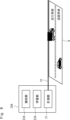
- FIG. 1 an example of an autonomous vehicle merging onto an expressway will be described.
- the example in FIG. 1 is an example in which an autonomous vehicle AC merges onto road R, which is an expressway with two lanes on each side (a driving lane and an overtaking lane).
- optical fiber 10 for optical fiber sensing is buried along the shoulder of road R.
- optical fiber sensing using the optical fiber 10 as a line sensor is capable of determining whether or not a vehicle is traveling in a region of interest, but it has been difficult for optical fiber sensing to determine whether a vehicle traveling in the region of interest is traveling in the driving lane or the overtaking lane.
- a fixed-point monitoring system such as a camera is installed just before the junction of road R.
- the area that can be monitored by the camera is the area centered on the junction, and it is not possible to monitor the entire area of interest.
- Patent Documents 1 and 2 For this reason, recently, techniques have been proposed for identifying the lane in which a vehicle is traveling by using optical fiber sensing (for example, see Patent Documents 1 and 2). For example, the technology described in Patent Document 1 identifies the lane in which a vehicle is traveling by utilizing the fact that when vibrations are applied in a lane close to the optical fiber, the signal strength obtained by optical fiber sensing becomes large, and when vibrations are applied in a lane far from the optical fiber, the signal strength obtained by optical fiber sensing becomes small.
- Patent Document 2 also identifies the lane in which a vehicle is traveling by utilizing the observation information that can be obtained by optical fiber sensing to identify the lane in which the vehicle is traveling when the road pavement differs for each lane.
- Patent Document 1 identifies the lane in which a vehicle is traveling by utilizing the fact that signal strength differs depending on the distance between the optical fiber and each lane.
- signal strength also differs depending on the size of the vehicle, there is a problem in that identifying the lane in which a vehicle is traveling using only signal strength results in poor identification accuracy.
- Patent Document 2 identifies the lane in which the vehicle is traveling by utilizing the fact that observation information that can identify the lane in which the vehicle is traveling can be acquired when the road pavement differs for each lane. Therefore, the technology described in Patent Document 2 has the problem that, even if it can identify the lane in which the vehicle is traveling when the road pavement is the same for each lane, the identification accuracy is poor.
- the objective of this disclosure is to provide a lane identification system, a lane identification device, and a lane identification method that can more accurately identify the lane in which a vehicle is traveling.
- a lane identification system includes: Optical fiber buried in the road, a measurement unit that measures vibration characteristics of vibrations generated on the road based on an optical signal received from the optical fiber; The system further includes an identification unit that derives vibration intensity when a vehicle passes through an observation point on the road based on vibration characteristics among the vibration characteristics when the vehicle passes through the observation point, and identifies the lane in which the vehicle that passed the observation point is traveling based on the derived vibration intensity and the vehicle classification of the vehicle that passed the observation point.
- a lane identification device includes: a measurement unit that measures vibration characteristics of vibrations generated on a road based on an optical signal received from an optical fiber buried in the road; The system further includes an identification unit that derives vibration intensity when a vehicle passes through an observation point on the road based on vibration characteristics among the vibration characteristics when the vehicle passes through the observation point, and identifies the lane in which the vehicle that passed the observation point is traveling based on the derived vibration intensity and the vehicle classification of the vehicle that passed the observation point.
- a lane identification method includes the steps of: A lane identification method executed by a lane identification device, comprising: a measuring step of measuring vibration characteristics of vibrations generated on a road based on an optical signal received from an optical fiber buried in the road; The method includes an identification step of deriving a vibration intensity when a vehicle passes an observation point on the road based on the vibration characteristics among the vibration characteristics when the vehicle passes the observation point, and identifying the lane in which the vehicle that passed the observation point is traveling based on the derived vibration intensity and the vehicle classification of the vehicle that passed the observation point.
- the above-mentioned aspects have the effect of providing a lane identification system, lane identification device, and lane identification method that can more accurately identify the lane in which a vehicle is traveling.
- FIG. 1 is a diagram showing an example of an autonomous vehicle merging into a driving lane on a highway.
- 1 is a diagram showing a schematic configuration example of a lane identification system according to a first embodiment
- 5A to 5C are diagrams illustrating an example of vibration measurement data generated by a learning unit and a recognition unit according to the first embodiment
- 5A to 5C are diagrams illustrating examples of vibration intensities derived by a learning unit and a recognition unit according to the first embodiment.
- FIG. 13 is a diagram showing an example of statistical data representing the relationship, for each vehicle classification, between the vibration intensity when a vehicle passes an observation point on a road and the lane in which the vehicle that passed the observation point on the road is traveling.
- 5A to 5C are diagrams illustrating examples of waveform lengths derived by a learning unit and a discrimination unit according to the first embodiment.
- 6A and 6B are diagrams illustrating an example of the number of peaks derived by a learning unit and a discrimination unit according to the first embodiment;
- 1 is a diagram showing a schematic operation example of a lane identification system according to a first embodiment;
- FIG. 11 is a diagram illustrating a schematic configuration example of a lane identification system according to a second embodiment.
- FIG. 11 is a diagram showing an example of statistical data representing the relationship, for each vehicle classification, between the vibration intensity and the vehicle's traveling speed when the vehicle passes an observation point on the road, and the lane in which the vehicle that passed the observation point on the road is traveling.
- FIG. 13A to 13C are diagrams illustrating another example of the vibration measurement data generated by the learning unit and the identification unit according to the second embodiment.
- FIG. 11 is a diagram showing a schematic operation example of a lane identification system according to a second embodiment
- FIG. 11 is a diagram illustrating a schematic configuration example of a lane identification system according to a third embodiment.
- FIG. 11 is a flow diagram showing an example of a schematic operation flow of a lane identification system according to a third embodiment.
- FIG. 2 is a block diagram showing a schematic hardware configuration example of a computer that realizes the lane identification device according to each embodiment.
- the lane identification system according to the first embodiment includes an optical fiber 10 and a lane identification device 20 .
- the optical fiber 10 is buried in the road R.
- the road R is a road with two lanes on each side (a driving lane and an overtaking lane), and the optical fiber 10 is buried under the shoulder of the road R along the road R.
- the road R may be a road with three or more lanes, and the optical fiber 10 may be buried under the central reservation.
- the lane identification device 20 is realized by a sensing device such as a Distributed Fiber Optic Sensing (DFOS) device.
- the lane identification device 20 includes a measurement unit 21, a learning unit 22, and an identification unit 23.
- DFOS Distributed Fiber Optic Sensing
- the optical fiber 10 is connected to the measuring unit 21 .
- the measuring unit 21 transmits pulsed light to the optical fiber 10.
- the measuring unit 21 receives backscattered light generated as the pulsed light is transmitted through the optical fiber 10 from the optical fiber 10 as an optical signal.
- the measurement unit 21 can detect vibrations occurring on the road R based on the optical signal received from the optical fiber 10. In addition, the measurement unit 21 can measure the amplitude of vibrations occurring on the road R based on the degree of change in the characteristics of the optical signal received from the optical fiber 10.
- the optical fiber 10 functions as a sensor when the measuring unit 21 detects vibrations.
- the sensors are distributed linearly along the optical fiber 10, so the optical fiber 10 functions as a line sensor.
- the measurement unit 21 can determine the position where the optical signal was generated, i.e., the position where the vibration on the road R detected based on the optical signal was generated (the distance of the optical fiber 10 from the lane identification device 20).
- the measurement unit 21 can measure the amplitude and the location of occurrence of the vibration (the distance of the optical fiber 10 from the lane identification device 20) as the vibration characteristics of the vibration occurring on the road R.
- the learning unit 22 generates measurement data in advance, in a learning phase, based on the measurement results of the measurement unit 21, which indicates the time-series vibration characteristics of vibrations occurring at an observation point, which is an arbitrary point on the road R.
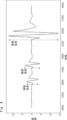
- Figure 3 shows an example of measurement data of vibrations occurring at an observation point on the road R.
- the horizontal axis indicates time
- the vertical axis indicates the amplitude of vibration.
- the waveform of the vibration generated as the vehicle travels has a unique waveform pattern in terms of the strength of the vibration, the vibration position, and the transition of the vibration frequency fluctuation.
- the learning unit 22 detects that a vehicle corresponding to that waveform has passed the observation point and extracts that waveform. For example, in the example of Figure 3, there are three waveforms corresponding respectively to three vehicles. Therefore, the learning unit 22 detects three vehicles and extracts three waveforms corresponding respectively to the three vehicles.
- the learning unit 22 derives the vibration intensity of the waveform as a feature based on the waveform corresponding to a vehicle that has passed an observation point on road R.
- Figure 4 shows an example of the vibration intensity derived based on the waveform corresponding to a vehicle. As shown in Figure 4, the vibration intensity corresponds to the difference between the maximum peak value and the minimum peak value of the waveform.
- the learning unit 22 generates a feature model that models the relationship between the vibration intensity when the vehicle passes an observation point on the road R and the lane in which the vehicle that passed the observation point is traveling, for each vehicle classification of the vehicle.
- the feature model is a model that represents the boundaries of the vibration intensity of each lane for each vehicle classification of the vehicle.
- the vehicle classification refers to the size (weight) of the vehicle, such as small, normal, large, etc.
- Figure 5 shows an example of statistical data that indicates the relationship between the vibration intensity when a vehicle passes an observation point on road R and the lane in which the vehicle that passed the observation point is traveling, for each vehicle classification.
- Figure 5 shows an example in which there are two vehicle classes: small vehicles and large vehicles.
- the horizontal axis indicates vibration intensity
- the vertical axis indicates the number of vehicles.
- vibration strength is characterized by being dependent on the lane in which the vehicle is traveling and the vehicle classification.
- the learning unit 22 can identify the lane in which a vehicle that has passed an observation point on road R is traveling and the vehicle classification of that vehicle based on the camera data.
- the learning unit 22 can identify the lane. For example, a driving test in which the vehicle travels on a predetermined lane meets the above conditions because the lane can be known in advance.
- the learning unit 22 may estimate the vehicle classification of the vehicle based on the measurement results of the measurement unit 21. For example, the learning unit 22 extracts a waveform corresponding to a vehicle that passed an observation point on road R from the measurement data used to derive the vibration intensity, and then derives the waveform length of the waveform as a feature based on the extracted waveform.
- FIG. 6 shows an example of the waveform length derived based on the waveform corresponding to a vehicle. As shown in FIG. 6, the waveform length corresponds to the vibration duration.
- the learning unit 22 may estimate the vehicle classification based on the waveform length.
- the learning unit 22 extracts from the measurement data a waveform corresponding to a vehicle that has passed an observation point on road R, and then derives the number of peaks in the waveform as a feature based on the extracted waveform.
- Figure 7 shows an example of the number of peaks derived based on a waveform corresponding to a vehicle.
- the area surrounded by a dashed circle corresponds to the peak. It is considered that a peak occurs when the axle of the vehicle passes an observation point on road R.
- the learning unit 22 may estimate the vehicle classification based on the number of peaks.
- the identification unit 23 In the operation phase, the identification unit 23 generates measurement data that indicates the time-series vibration characteristics of the vibrations that occur at the observation point on the road R based on the measurement results of the measurement unit 21.
- An example of this measurement data is the same as that shown in FIG. 3.
- the identification unit 23 detects a vehicle that has passed the observation point on road R based on the waveform of the measurement data of the vibration generated at the observation point, and if a vehicle that has passed the observation point is detected, it extracts the waveform corresponding to the vehicle that has passed the observation point.
- the identification unit 23 derives the vibration intensity of the waveform as a feature based on the waveform corresponding to the vehicle that passed the observation point on road R. The identification unit 23 then identifies the lane in which the vehicle that passed the observation point is traveling based on the derived vibration intensity, the vehicle classification of the vehicle that passed the observation point, and the feature model generated by the learning unit 22.
- the identification unit 23 outputs the identified lane as the identification result.
- the identification result may be output to a management system that manages the road R, or a terminal in a management room that manages the road R, etc.
- the identification unit 23 may estimate the vehicle classification of the vehicle based on the measurement results of the measurement unit 21.
- the method of estimating the vehicle classification in the identification unit 23 may be the same as that of the learning unit 22 described above.
- the learning unit 22 generates measurement data indicating time-series vibration characteristics of vibrations occurring at observation points on the road R based on the measurement results of the measurement unit 21 (step X11).
- the learning unit 22 detects a vehicle that has passed the observation point on road R based on the waveform of the measurement data of the vibration generated at the observation point (step X12). If a vehicle that has passed the observation point is detected, the measurement unit 21 extracts a waveform corresponding to the vehicle that has passed the observation point (step X13).
- the learning unit 22 derives the vibration intensity of the waveform as a feature based on the waveform corresponding to the vehicle that passed the observation point on road R (step X14).
- the learning unit 22 generates a feature model that models the relationship between the vibration intensity when the vehicle passes an observation point on the road R and the lane in which the vehicle that passed the observation point is traveling, for each vehicle classification (step X15).
- the identification unit 23 generates measurement data indicating time-series vibration characteristics of vibrations occurring at the observation point on the road R based on the measurement results of the measurement unit 21 (step Y11).
- the measurement unit 21 detects a vehicle that has passed the observation point on road R based on the waveform of the measurement data of the vibration generated at the observation point (step Y12). If a vehicle that has passed the observation point is detected, the measurement unit 21 extracts a waveform corresponding to the vehicle that has passed the observation point (step Y13).
- the identification unit 23 derives the vibration intensity of the waveform as a feature based on the waveform corresponding to the vehicle that passed the observation point on road R (step Y14).
- the identification unit 23 identifies the lane in which the vehicle that passed the observation point on road R is traveling based on the derived waveform length, the vehicle classification of the vehicle that passed the observation point, and the feature model generated by the learning unit 22 (step Y15).
- the identification unit 23 outputs the identified lane as the identification result for the vehicle that passed the observation point on the road R (step Y16).
- the measurement unit 21 measures the vibration characteristics of the vibration generated on the road R based on the optical signal received from the optical fiber 10.
- the learning unit 22 derives the vibration strength based on the vibration characteristics when the vehicle passes the observation point on the road R among the vibration characteristics measured by the measurement unit 21, and generates a feature quantity model that models the relationship between the vibration strength when the vehicle passes the observation point on the road R and the lane in which the vehicle is traveling for each vehicle classification of the vehicle.
- the identification unit 23 derives the vibration strength based on the vibration characteristics when the vehicle passes the observation point among the vibration characteristics measured by the measurement unit 21, and identifies the lane in which the vehicle is traveling based on the derived vibration strength, the vehicle classification of the vehicle, and the feature quantity model. In this way, the lane in which the vehicle is traveling is identified using the vehicle classification of the vehicle in addition to the vibration strength when the vehicle passes the observation point. Therefore, the lane in which the vehicle is traveling can be identified more accurately compared to the related technology.
- the lane in which the vehicle is traveling is identified by utilizing the vibration intensity when the vehicle passes an observation point on the road R and the vehicle classification of the vehicle.
- the vehicle's traveling speed is also used to identify the lane in which the vehicle is traveling.
- the lane identification system according to the second embodiment is configured such that the lane identification device 20 is replaced with a lane identification device 20A, as compared with the lane identification system according to the first embodiment described above.
- the lane identification device 20A has a configuration in which the learning unit 22 and the identification unit 23 are replaced with a learning unit 22A and an identification unit 23A.
- the learning unit 22A generates measurement data (as shown in FIG. 3) in advance during the learning phase, based on the measurement results of the measurement unit 21, which indicates the time-series vibration characteristics of the vibrations occurring at the observation points on the road R.
- the learning unit 22A detects a vehicle that has passed the observation point on road R based on the waveform of the measurement data of the vibration generated at the observation point, and if a vehicle that has passed the observation point is detected, it extracts the waveform corresponding to the vehicle that has passed the observation point.
- the learning unit 22A derives the vibration intensity of the waveform as a feature based on the waveform corresponding to the vehicle that passed the observation point on the road R.
- the learning unit 22A generates a feature quantity model that models the relationship between the vibration intensity when the vehicle passes an observation point on the road R, the traveling speed of the vehicle that passed the observation point, and the lane in which the vehicle that passed the observation point is traveling, for each vehicle classification of the vehicle.
- the feature quantity model is a model that represents the boundaries of the vibration intensity and traveling speed of each lane, for each vehicle classification of the vehicle.
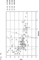
- Figure 10 shows an example of statistical data that indicates the relationship between the vibration intensity when a vehicle passes an observation point on road R, the traveling speed of the vehicle that passed the observation point, and the lane in which the vehicle that passed the observation point is traveling, for each vehicle classification of the vehicle.
- Figure 10 shows an example in which there are two vehicle classes: small vehicles and large vehicles.
- the horizontal axis indicates vibration intensity
- the vertical axis indicates the traveling speed of the vehicle.
- the vibration strength is characterized by being dependent on the lane in which the vehicle is traveling and the vehicle classification.
- the traveling speed is characterized by being dependent on the lane in which the vehicle is traveling.
- the learning unit 22A can identify the lane in which a vehicle that has passed an observation point on road R is traveling and the vehicle classification of the vehicle based on the camera data.
- the learning unit 22A can identify the lane. For example, a driving test in which the vehicle travels on a predetermined lane meets the above conditions because the lane can be known in advance.
- the learning unit 22A may estimate the vehicle classification and traveling speed of the vehicle based on the measurement results of the measurement unit 21. For example, the learning unit 22A generates measurement data as shown in Fig. 11 based on the measurement results of the measurement unit 21.
- the horizontal axis indicates the distance of the optical fiber 10 from the lane identification device 20, and the vertical axis indicates the time lapse from the time when the vibration occurred. The data becomes older as the vertical axis moves in the positive direction.
- one vehicle traveling on road R is represented by a single diagonal line.
- the absolute value of the slope of the line represents the vehicle's traveling speed, and the smaller the absolute value of the slope of the line, the faster the vehicle is traveling.
- the positive or negative slope of the line represents the vehicle's traveling direction.
- the interval between the lines in the horizontal direction represents the distance between the vehicles, and the shorter the interval, the shorter the distance between the vehicles.
- the learning unit 22A may identify a vehicle based on the time when the vehicle passed the observation point in the measurement data shown in Figure 11, and estimate the vehicle's traveling speed based on the absolute value of the slope of the line corresponding to that vehicle.
- the method for estimating the vehicle classification in the learning unit 22A may be the same as that in the first embodiment described above.
- the identification unit 23A In the operation phase, the identification unit 23A generates measurement data (measurement data as shown in FIG. 3) that indicates the time-series vibration characteristics of the vibrations occurring at the observation point on the road R based on the measurement results of the measurement unit 21.
- the identification unit 23A detects a vehicle that has passed the observation point on road R based on the waveform of the measurement data of the vibrations that have occurred at the observation point, and if a vehicle that has passed the observation point is detected, it extracts the waveform corresponding to the vehicle that has passed the observation point.
- the identification unit 23A derives the vibration intensity of the waveform as a feature based on the waveform corresponding to the vehicle that passed the observation point on road R. The identification unit 23A then identifies the lane in which the vehicle that passed the observation point is traveling based on the derived vibration intensity, the vehicle classification and traveling speed of the vehicle that passed the observation point, and the feature model generated by the learning unit 22A.
- the identification unit 23A outputs the identified lane as the identification result.
- the output destination of the identification result may be the same as in the first embodiment described above.
- the identification unit 23A may estimate the vehicle classification and traveling speed of the vehicle based on the measurement results of the measurement unit 21.
- the method of estimating the vehicle classification and traveling speed in the identification unit 23A may be the same as that of the learning unit 22A described above.
- the learning unit 22A performs the processes of steps X21 to X24 similar to steps X11 to X14 in FIG. 8 of the above-mentioned first embodiment.
- the learning unit 22A generates a feature model that models the relationship between the vibration intensity when the vehicle passes an observation point on the road R, the traveling speed of the vehicle that passed the observation point, and the lane in which the vehicle that passed the observation point is traveling, for each vehicle classification of the vehicle (step X25).
- the recognition unit 23A performs the processes of steps Y21 to Y24 similar to steps Y11 to Y14 in FIG. 8 of the above-mentioned first embodiment.
- the identification unit 23A identifies the lane in which the vehicle that passed the observation point is traveling based on the derived vibration intensity, the vehicle classification and traveling speed of the vehicle that passed the observation point on the road R, and the feature model generated by the learning unit 22A (step Y25).
- the identification unit 23A outputs the identified lane as the identification result for the vehicle that passed the observation point on the road R (step Y26).
- the measurement unit 21 measures the vibration characteristics of the vibration generated on the road R, as in the first embodiment.
- the learning unit 22A derives the vibration intensity based on the vibration characteristics when the vehicle passes the observation point on the road R among the vibration characteristics measured by the measurement unit 21, and generates a feature quantity model that models the relationship between the vibration intensity when the vehicle passes the observation point on the road R, the traveling speed of the vehicle, and the lane in which the vehicle is traveling, for each vehicle classification of the vehicle.
- the identification unit 23A derives the vibration intensity based on the vibration characteristics when the vehicle passes the observation point among the vibration characteristics measured by the measurement unit 21, and identifies the lane in which the vehicle is traveling based on the derived vibration intensity, the vehicle classification and traveling speed of the vehicle, and the feature quantity model. In this way, the lane in which the vehicle is traveling is identified using the vehicle classification and traveling speed of the vehicle in addition to the vibration intensity when the vehicle passes the observation point. Therefore, compared to the related art and the above-mentioned embodiment 1, the lane in which the vehicle is traveling can be identified with greater accuracy.
- the third embodiment corresponds to an embodiment that is a superordinate concept of the first and second embodiments described above.
- the lane identification system according to the third embodiment includes an optical fiber 10 and a lane identification device 20B.
- the lane identification device 20B includes a measurement unit 21B and an identification unit 23B.
- the measuring unit 21B measures the vibration characteristics of the vibration generated on the road R based on the optical signal received from the optical fiber 10 buried in the road R.
- the identification unit 23B derives the vibration intensity when the vehicle passes the observation point on road R, based on the vibration characteristics measured by the measurement unit 21B when the vehicle passes the observation point. Furthermore, the identification unit 23B identifies the lane in which the vehicle that passed the observation point is traveling, based on the derived vibration intensity and the vehicle classification of the vehicle that passed the observation point.
- the measurement unit 21B measures the vibration characteristics of the vibration generated on the road R based on the optical signal received from the optical fiber 10 buried in the road R (step S11).
- the identification unit 23B derives the vibration intensity when the vehicle passes the observation point on road R based on the vibration characteristics measured by the measurement unit 21B when the vehicle passes the observation point (step S12).
- the identification unit 23B identifies the lane in which the vehicle that passed the observation point is traveling based on the derived vibration intensity and the vehicle classification of the vehicle that passed the observation point (step S13).
- the measurement unit 21B measures the vibration characteristics of the vibrations generated on the road R based on the optical signal received from the optical fiber 10 buried in the road R.
- the identification unit 23B derives the vibration intensity when the vehicle passes the observation point on the road R based on the vibration characteristics measured by the measurement unit 21B when the vehicle passes the observation point.
- the identification unit 23B also identifies the lane in which the vehicle that passed the observation point is traveling based on the derived vibration intensity and the vehicle classification of the vehicle that passed the observation point. In this way, the lane in which the vehicle is traveling is identified using the vehicle classification of the vehicle in addition to the vibration intensity when the vehicle passed the observation point. Therefore, the lane in which the vehicle is traveling can be identified with greater accuracy compared to the related technology.
- the identification unit 23B may also estimate the vehicle classification of a vehicle that has passed an observation point on road R based on the vibration characteristics when the vehicle passes the observation point, and identify the lane in which the vehicle that has passed the observation point is traveling based on the derived vibration intensity and the estimated vehicle classification.
- the lane identification device 20B may further include a learning unit that generates a feature model that models the relationship between the vibration intensity when a vehicle passes an observation point on road R and the lane in which the vehicle that passed the observation point is traveling, for each vehicle classification of the vehicle in advance.
- the identification unit 23B may identify the lane in which the vehicle that passed the observation point is traveling, based on the derived vibration intensity, the vehicle classification of the vehicle that passed the observation point, and the feature model.
- the identification unit 23B may also identify the lane in which a vehicle that has passed the observation point is traveling, based on the derived vibration intensity and the vehicle classification and traveling speed of the vehicle that has passed the observation point on the road R.
- the identification unit 23B may also estimate the vehicle classification and traveling speed of a vehicle that has passed the observation point based on the vibration characteristics of the vibrations that have occurred on the road R, and identify the lane in which the vehicle that has passed the observation point is traveling based on the derived vibration strength and the estimated vehicle classification and traveling speed.
- the lane identification device 20B may further include a learning unit that generates a feature quantity model that models the relationship between the vibration intensity when the vehicle passes an observation point on the road R and the traveling speed of the vehicle that passed the observation point, and the lane in which the vehicle that passed the observation point is traveling, for each vehicle classification of the vehicle.
- the identification unit 23B may identify the lane in which the vehicle that passed the observation point is traveling, based on the derived vibration intensity, the vehicle classification and traveling speed of the vehicle that passed the observation point, and the feature quantity model.
- the learning unit 22 and the identification unit 23 are provided inside the lane identification device 20, but this is not limiting.
- the learning unit 22 and the identification unit 23 may be provided in a device separate from the lane identification device 20, or may be provided on the cloud.
- the computer 90 includes a processor 91, a memory 92, a storage 93, an input/output interface (input/output I/F) 94, and a communication interface (communication I/F) 95.
- the processor 91, the memory 92, the storage 93, the input/output interface 94, and the communication interface 95 are connected by a data transmission path for transmitting and receiving data to and from each other.
- the processor 91 is, for example, an arithmetic processing device such as a CPU (Central Processing Unit) or a GPU (Graphics Processing Unit).
- the memory 92 is, for example, a memory such as a RAM (Random Access Memory) or a ROM (Read Only Memory).
- the storage 93 is, for example, a storage device such as a HDD (Hard Disk Drive), an SSD (Solid State Drive), or a memory card.
- the storage 93 may also be a memory such as a RAM or ROM.
- Storage 93 stores programs that realize the functions of the components of lane identification devices 20, 20A, and 20B.
- Processor 91 executes each of these programs to realize the functions of the components of lane identification devices 20, 20A, and 20B.
- processor 91 may read these programs onto memory 92 before executing them, or may execute them without reading them onto memory 92.
- Memory 92 and storage 93 also serve to store information and data held by the components of lane identification devices 20, 20A, and 20B.
- Non-transitory computer readable medium includes various types of tangible storage medium.
- Examples of non-transitory computer readable medium include magnetic recording media (e.g., flexible disks, magnetic tapes, hard disk drives), magneto-optical recording media (e.g., magneto-optical disks), Compact Disc-ROM (CD-ROM), CD-Recordable (CD-R), CD-ReWritable (CD-R/W), and semiconductor memory (e.g., mask ROM, Programmable ROM (PROM), Erasable PROM (EPROM), flash ROM, RAM).
- magnetic recording media e.g., flexible disks, magnetic tapes, hard disk drives
- magneto-optical recording media e.g., magneto-optical disks
- CD-ROM Compact Disc-ROM
- CD-R CD-Recordable
- CD-R/W CD-ReWritable
- semiconductor memory e.g., mask ROM, Programmable ROM (PROM), Erasable PROM (EPROM), flash ROM,
- the program may also be supplied to a computer by various types of transitory computer readable medium.
- Examples of transitory computer readable medium include electrical signals, optical signals, and electromagnetic waves.
- the temporary computer-readable medium can provide the program to the computer via a wired communication path, such as an electric wire or optical fiber, or via a wireless communication path.
- the input/output interface 94 is connected to a display device 941, an input device 942, a sound output device 943, etc.
- the display device 941 is a device that displays a screen corresponding to drawing data processed by the processor 91, such as an LCD (Liquid Crystal Display), a CRT (Cathode Ray Tube) display, or a monitor.
- the input device 942 is a device that accepts operational input from an operator, such as a keyboard, a mouse, or a touch sensor.
- the display device 941 and the input device 942 may be integrated and realized as a touch panel.
- the sound output device 943 is a device that acoustically outputs sound corresponding to the audio data processed by the processor 91, such as a speaker.
- the communication interface 95 transmits and receives data to and from an external device.
- the communication interface 95 communicates with the external device via a wired communication path or a wireless communication path.
- (Appendix 1) Optical fiber buried in the road, a measurement unit that measures vibration characteristics of vibrations generated on the road based on an optical signal received from the optical fiber; an identification unit that derives a vibration intensity when a vehicle passes through an observation point on the road based on vibration characteristics among the vibration characteristics when the vehicle passes through the observation point, and identifies a lane in which the vehicle that passed the observation point is traveling based on the derived vibration intensity and a vehicle classification of the vehicle that passed the observation point. Lane identification system.
- the identification unit is estimating a vehicle classification of a vehicle that has passed the observation point based on vibration characteristics when the vehicle has passed the observation point; identifying a lane in which a vehicle that has passed the observation point is traveling based on the derived vibration strength and the estimated vehicle classification; 2.
- (Appendix 3) a learning unit that generates a feature quantity model that models a relationship between a vibration intensity when a vehicle passes the observation point and a lane in which the vehicle that has passed the observation point is traveling, for each vehicle classification of the vehicle in advance; the identification unit identifies a lane in which a vehicle that has passed the observation point is traveling, based on the derived vibration intensity, a vehicle classification of the vehicle that has passed the observation point, and the feature model. 3.
- the lane identification system of claim 1. (Appendix 5)
- the identification unit is estimating a vehicle classification and a traveling speed of a vehicle that has passed the observation point based on the vibration characteristics; identifying a lane in which a vehicle that has passed the observation point is traveling based on the derived vibration strength and the estimated vehicle classification and traveling speed; 5.
- a learning unit that generates a feature quantity model that models a relationship between a vibration intensity when a vehicle passes the observation point, a traveling speed of the vehicle that passed the observation point, and a lane in which the vehicle that passed the observation point is traveling, for each vehicle classification of the vehicle in advance; the identification unit identifies a lane in which a vehicle that has passed the observation point is traveling, based on the derived vibration intensity, a vehicle classification and a traveling speed of the vehicle that has passed the observation point, and the feature model. 6.
- a lane identification system according to claim 4 or 5.
- (Appendix 7) a measurement unit that measures vibration characteristics of vibrations generated on a road based on an optical signal received from an optical fiber buried in the road; an identification unit that derives a vibration intensity when a vehicle passes through an observation point on the road based on vibration characteristics among the vibration characteristics when the vehicle passes through the observation point, and identifies a lane in which the vehicle that passed the observation point is traveling based on the derived vibration intensity and a vehicle classification of the vehicle that passed the observation point.
- Lane identification device
- the identification unit is estimating a vehicle classification of a vehicle that has passed the observation point based on vibration characteristics when the vehicle has passed the observation point; identifying a lane in which a vehicle that has passed the observation point is traveling based on the derived vibration strength and the estimated vehicle classification; 8.
- a learning unit that generates a feature quantity model that models a relationship between a vibration intensity when a vehicle passes the observation point and a lane in which the vehicle that has passed the observation point is traveling, for each vehicle classification of the vehicle in advance; the identification unit identifies a lane in which a vehicle that has passed the observation point is traveling, based on the derived vibration intensity, a vehicle classification of the vehicle that has passed the observation point, and the feature model.
- the identification unit identifies a lane in which a vehicle that has passed the observation point is traveling, based on the derived vibration intensity, and a vehicle classification and a traveling speed of the vehicle that has passed the observation point.
- the lane identification device of claim 7. (Appendix 11)
- the identification unit is estimating a vehicle classification and a traveling speed of a vehicle that has passed the observation point based on the vibration characteristics; identifying a lane in which a vehicle that has passed the observation point is traveling based on the derived vibration strength and the estimated vehicle classification and traveling speed; 11.
- (Appendix 12) a learning unit that generates a feature quantity model that models a relationship between a vibration intensity when a vehicle passes the observation point, a traveling speed of the vehicle that passed the observation point, and a lane in which the vehicle that passed the observation point is traveling, for each vehicle classification of the vehicle in advance; the identification unit identifies a lane in which a vehicle that has passed the observation point is traveling, based on the derived vibration intensity, a vehicle classification and a traveling speed of the vehicle that has passed the observation point, and the feature model. 12.
- the lane identification device according to claim 10 or 11.
- a lane identification method executed by a lane identification device comprising: a measuring step of measuring vibration characteristics of vibrations generated on a road based on an optical signal received from an optical fiber buried in the road; and an identification step of deriving a vibration intensity when a vehicle passes an observation point on the road based on the vibration characteristics among the vibration characteristics when the vehicle passes the observation point, and identifying a lane in which the vehicle that passed the observation point is traveling based on the derived vibration intensity and a vehicle classification of the vehicle that passed the observation point.
- Lane identification methods executed by a lane identification device, comprising: a measuring step of measuring vibration characteristics of vibrations generated on a road based on an optical signal received from an optical fiber buried in the road; and an identification step of deriving a vibration intensity when a vehicle passes an observation point on the road based on the vibration characteristics among the vibration characteristics when the vehicle passes the observation point, and identifying a lane in which the vehicle that passed the observation point is traveling based on the derived vibration intensity and a vehicle classification of the
- a lane in which a vehicle that has passed the observation point is traveling is identified based on the derived vibration intensity, a vehicle classification of the vehicle that has passed the observation point, and the feature model.
- Appendix 16 In the identification step, a lane in which a vehicle that has passed the observation point is traveling is identified based on the derived vibration intensity, and a vehicle classification and a traveling speed of the vehicle that has passed the observation point. 14.
- the lane identification method according to claim 13. (Appendix 17) In the identifying step, estimating a vehicle classification and a traveling speed of a vehicle that has passed the observation point based on the vibration characteristics; identifying a lane in which a vehicle that has passed the observation point is traveling based on the derived vibration strength and the estimated vehicle classification and traveling speed; 17. The lane identification method according to claim 16.
- (Appendix 18) a learning step of generating, in advance, a feature model that models a relationship between a vibration intensity when a vehicle passes the observation point, a traveling speed of the vehicle that has passed the observation point, and a lane in which the vehicle that has passed the observation point is traveling, for each vehicle classification of the vehicle;
- a lane in which a vehicle that has passed the observation point is traveling is identified based on the derived vibration intensity, a vehicle classification and a traveling speed of the vehicle that has passed the observation point, and the feature model.
Landscapes
- Physics & Mathematics (AREA)
- General Physics & Mathematics (AREA)
- Traffic Control Systems (AREA)
Priority Applications (2)
| Application Number | Priority Date | Filing Date | Title |
|---|---|---|---|
| PCT/JP2023/016732 WO2024224569A1 (ja) | 2023-04-27 | 2023-04-27 | 車線識別システム、車線識別装置、及び車線識別方法 |
| JP2025516423A JPWO2024224569A1 (https=) | 2023-04-27 | 2023-04-27 |
Applications Claiming Priority (1)
| Application Number | Priority Date | Filing Date | Title |
|---|---|---|---|
| PCT/JP2023/016732 WO2024224569A1 (ja) | 2023-04-27 | 2023-04-27 | 車線識別システム、車線識別装置、及び車線識別方法 |
Publications (1)
| Publication Number | Publication Date |
|---|---|
| WO2024224569A1 true WO2024224569A1 (ja) | 2024-10-31 |
Family
ID=93256235
Family Applications (1)
| Application Number | Title | Priority Date | Filing Date |
|---|---|---|---|
| PCT/JP2023/016732 Ceased WO2024224569A1 (ja) | 2023-04-27 | 2023-04-27 | 車線識別システム、車線識別装置、及び車線識別方法 |
Country Status (2)
| Country | Link |
|---|---|
| JP (1) | JPWO2024224569A1 (https=) |
| WO (1) | WO2024224569A1 (https=) |
Citations (6)
| Publication number | Priority date | Publication date | Assignee | Title |
|---|---|---|---|---|
| JP2004523042A (ja) * | 2001-02-15 | 2004-07-29 | キネテイツク・リミテツド | 道路交通モニタリングシステム |
| JP2004252520A (ja) * | 2003-02-18 | 2004-09-09 | Sumitomo Electric Ind Ltd | 道路監視システム |
| US20180342156A1 (en) * | 2015-10-30 | 2018-11-29 | Optasense Holdings Limited | Monitoring Traffic Flow |
| JP2021121917A (ja) * | 2020-01-30 | 2021-08-26 | 日本電気株式会社 | 交通監視装置および交通監視方法 |
| WO2022024208A1 (ja) * | 2020-07-28 | 2022-02-03 | 日本電気株式会社 | 交通監視装置、交通監視システム、交通監視方法及びプログラム |
| WO2023053184A1 (ja) * | 2021-09-28 | 2023-04-06 | 日本電気株式会社 | 光ファイバセンシングシステム、光ファイバセンシング機器、及び道路監視方法 |
-
2023
- 2023-04-27 JP JP2025516423A patent/JPWO2024224569A1/ja active Pending
- 2023-04-27 WO PCT/JP2023/016732 patent/WO2024224569A1/ja not_active Ceased
Patent Citations (6)
| Publication number | Priority date | Publication date | Assignee | Title |
|---|---|---|---|---|
| JP2004523042A (ja) * | 2001-02-15 | 2004-07-29 | キネテイツク・リミテツド | 道路交通モニタリングシステム |
| JP2004252520A (ja) * | 2003-02-18 | 2004-09-09 | Sumitomo Electric Ind Ltd | 道路監視システム |
| US20180342156A1 (en) * | 2015-10-30 | 2018-11-29 | Optasense Holdings Limited | Monitoring Traffic Flow |
| JP2021121917A (ja) * | 2020-01-30 | 2021-08-26 | 日本電気株式会社 | 交通監視装置および交通監視方法 |
| WO2022024208A1 (ja) * | 2020-07-28 | 2022-02-03 | 日本電気株式会社 | 交通監視装置、交通監視システム、交通監視方法及びプログラム |
| WO2023053184A1 (ja) * | 2021-09-28 | 2023-04-06 | 日本電気株式会社 | 光ファイバセンシングシステム、光ファイバセンシング機器、及び道路監視方法 |
Also Published As
| Publication number | Publication date |
|---|---|
| JPWO2024224569A1 (https=) | 2024-10-31 |
Similar Documents
| Publication | Publication Date | Title |
|---|---|---|
| JP2021121917A (ja) | 交通監視装置および交通監視方法 | |
| JP2023184539A (ja) | 道路監視システム、道路監視装置、道路監視方法、及びプログラム | |
| CN110696826B (zh) | 用于控制车辆的方法和装置 | |
| CN109472885A (zh) | 轮胎安全管理方法、装置、轮胎安全管理设备及汽车 | |
| JP2017111813A (ja) | 不確実性ベースの交通渋滞指標を生成するための方法、コンピュータ可読ストレージ媒体、およびシステム | |
| CN109696664B (zh) | 一种超声波同频干扰的检测方法及检测装置 | |
| WO2022024208A1 (ja) | 交通監視装置、交通監視システム、交通監視方法及びプログラム | |
| CN111127793A (zh) | 电缆防盗监测方法和系统、计算机可读存储介质 | |
| JP7424394B2 (ja) | 車両監視システム、車両監視方法、及び車両監視装置 | |
| JP2024516568A (ja) | 光ファイバセンシングを用いたマッピング | |
| CN109637148B (zh) | 车载鸣笛监控系统、方法、存储介质及设备 | |
| CN110703753A (zh) | 路径规划方法及装置、电子设备、存储介质 | |
| CN112651535A (zh) | 局部路径规划方法、装置、存储介质、电子设备及车辆 | |
| US12535353B2 (en) | Position evaluation apparatus, position evaluation method, and non-transitory computer readable medium | |
| WO2018019144A1 (zh) | 一种导航对象确定方法及装置 | |
| WO2024224569A1 (ja) | 車線識別システム、車線識別装置、及び車線識別方法 | |
| US20250137839A1 (en) | Vehicle vibration extraction system, vehicle vibration extraction apparatus, and vehicle vibration extraction method | |
| CN117227792B (zh) | 一种轨道邻线干扰处理方法、装置、电子设备及存储介质 | |
| CN114842431A (zh) | 一种识别道路护栏的方法、装置、设备及存储介质 | |
| US20230349750A1 (en) | Structure deterioration detection system, structure deterioration detection method, and structure deterioration detection device | |
| CN113450794B (zh) | 导航播报的检测方法、装置、电子设备和介质 | |
| US20250191464A1 (en) | Lane change detection apparatus, lane change detection method, and non-transitory computer-readable medium | |
| JP7505645B2 (ja) | 敷設状態特定システム、敷設状態特定装置、及び敷設状態特定方法 | |
| US20260018049A1 (en) | Traffic monitoring device, traffic monitoring method, and non-transitory computer-readable medium | |
| WO2024224570A1 (ja) | 車両区分識別システム、車両区分識別装置、及び車両区分識別方法 |
Legal Events
| Date | Code | Title | Description |
|---|---|---|---|
| 121 | Ep: the epo has been informed by wipo that ep was designated in this application |
Ref document number: 23935347 Country of ref document: EP Kind code of ref document: A1 |
|
| ENP | Entry into the national phase |
Ref document number: 2025516423 Country of ref document: JP Kind code of ref document: A |
|
| WWE | Wipo information: entry into national phase |
Ref document number: 2025516423 Country of ref document: JP |
|
| NENP | Non-entry into the national phase |
Ref country code: DE |