WO2024224500A1 - 内燃機関の制御装置 - Google Patents
内燃機関の制御装置 Download PDFInfo
- Publication number
- WO2024224500A1 WO2024224500A1 PCT/JP2023/016400 JP2023016400W WO2024224500A1 WO 2024224500 A1 WO2024224500 A1 WO 2024224500A1 JP 2023016400 W JP2023016400 W JP 2023016400W WO 2024224500 A1 WO2024224500 A1 WO 2024224500A1
- Authority
- WO
- WIPO (PCT)
- Prior art keywords
- gas pressure
- crank angle
- cylinder
- combustion
- angle
- Prior art date
- Legal status (The legal status is an assumption and is not a legal conclusion. Google has not performed a legal analysis and makes no representation as to the accuracy of the status listed.)
- Ceased
Links
Images






Classifications
-
- F—MECHANICAL ENGINEERING; LIGHTING; HEATING; WEAPONS; BLASTING
- F02—COMBUSTION ENGINES; HOT-GAS OR COMBUSTION-PRODUCT ENGINE PLANTS
- F02D—CONTROLLING COMBUSTION ENGINES
- F02D45/00—Electrical control not provided for in groups F02D41/00 - F02D43/00
Definitions
- This application relates to a control device for an internal combustion engine.
- Pre-ignition known as abnormal combustion, is a phenomenon in which deposits remaining in the spark plug or cylinder become hot, acting as a heat source and causing self-ignition before ignition by the spark plug.
- the technology in Patent Document 1 detects pre-ignition based on the range of fluctuations in the rotational speed of the internal combustion engine.
- the output of the internal combustion engine decreases and the rotation speed of the internal combustion engine fluctuates.
- the occurrence of pre-ignition is detected by determining whether the fluctuation range of this rotation speed is smaller than a predetermined range (fluctuation range for detecting pre-ignition).
- pre-ignition including LSPI (Low Speed Pre-Ignition), which occurs especially at low revolutions and high loads, not only advances the timing of the start of combustion, but also involves rapid combustion, which leads to an earlier increase in gas pressure in the cylinder and a sudden increase in gas pressure in the cylinder.
- LSPI Low Speed Pre-Ignition
- the conversion of the force acting on the piston due to the increase in gas pressure caused by pre-ignition into crank angular acceleration is angle-dependent, and near top dead center where pre-ignition occurs, the conversion coefficient approaches 0, and the impact of pre-ignition on crank angular acceleration is small. For this reason, it is difficult to detect the occurrence of pre-ignition with accuracy using detection methods that capture rotational fluctuations.
- methods that directly detect gas pressure in the cylinder by adding an internal cylinder pressure sensor increase costs.
- the present application therefore aims to provide a control device for an internal combustion engine that can determine the occurrence of abnormal combustion using parameters that have little angle dependency and that are strongly influenced by the occurrence of abnormal combustion.
- the control device for an internal combustion engine comprises: an angle information detection unit that detects a crank angle and a crank angular acceleration based on an output signal of the crank angle sensor; a gas pressure calculation unit that calculates, for each of the crank angles, an increment in gas pressure torque due to combustion, among the gas pressure torque applied to the crankshaft by the gas pressure in a cylinder, based on the crank angle and the crank angular acceleration, and calculates, for each of the crank angles, an increment in gas pressure torque due to combustion, based on the increment in gas pressure torque due to combustion and the crank angle; an abnormal combustion determination unit that determines whether or not abnormal combustion has occurred in the internal combustion engine based on an increment in gas pressure due to the combustion at each crank angle within a determination angle section that is set corresponding to a combustion period; It is equipped with the following:
- the increase in gas pressure due to combustion has little angle dependency and is a good indicator of the effects of abnormal combustion. Therefore, the presence or absence of abnormal combustion can be accurately determined based on the increase in gas pressure due to combustion.
- FIG. 1 is a schematic configuration diagram of an internal combustion engine and a control device for the internal combustion engine according to a first embodiment
- 1 is a schematic configuration diagram of an internal combustion engine and a control device for the internal combustion engine according to a first embodiment
- 1 is a block diagram of a control device for an internal combustion engine according to a first embodiment.
- 1 is a hardware configuration diagram of a control device for an internal combustion engine according to a first embodiment
- 4 is a time chart for explaining an angle information detection process according to the first embodiment.
- FIG. 2 is a diagram for explaining the determination of the occurrence of pre-ignition according to the first embodiment.
- FIG. 2 is a diagram for explaining the determination of the occurrence of pre-ignition according to the first embodiment.
- FIG. 5 is a diagram for explaining the behavior of gas pressure in a cylinder during normal combustion according to the first embodiment.
- FIG. 4 is a diagram for explaining the behavior of gas pressure in a cylinder when pre-ignition occurs in the first embodiment.
- FIG. FIG. 2 is a diagram for explaining the determination of the occurrence of pre-ignition according to the first embodiment.
- FIG. 2 is a diagram for explaining the determination of the occurrence of pre-ignition according to the first embodiment.
- FIG. 4 is a diagram for explaining a misfire occurrence determination according to the first embodiment.
- FIG. 4 is a diagram for explaining a misfire occurrence determination according to the first embodiment.
- 5 is a diagram for explaining the behavior of gas pressure in a cylinder when a misfire occurs in the first embodiment.
- FIG. 5 is a diagram for explaining the behavior of gas pressure in a cylinder according to the first embodiment.
- FIG. FIG. 11 is a diagram for explaining the determination of the occurrence of pre-ignition according to the second embodiment.
- FIG. 11 is a diagram for explaining a misfire occurrence determination according to the second embodiment.
- FIG. 11 is a diagram for explaining the determination of the occurrence of pre-ignition according to the second embodiment.
- FIG. 11 is a diagram for explaining a misfire occurrence determination according to the second embodiment.
- FIG. 1 A control device 50 for an internal combustion engine 1 according to a first embodiment (hereinafter simply referred to as the control device 50) will be described with reference to the drawings.
- Figures 1 and 2 are schematic configuration diagrams of the internal combustion engine 1 and the control device 50 according to this embodiment
- Figure 3 is a block diagram of the control device 50 according to this embodiment.
- the internal combustion engine 1 and the control device 50 are mounted on a vehicle, and the internal combustion engine 1 serves as a driving force source for the vehicle (wheels).
- the internal combustion engine 1 has a cylinder 7 that burns a mixture of air and fuel.
- the internal combustion engine 1 has an intake pipe 23 that supplies air to the cylinder 7, and an exhaust pipe 17 that discharges exhaust gas burned in the cylinder 7.
- the internal combustion engine 1 is a gasoline engine.
- the internal combustion engine 1 has a throttle valve 4 that opens and closes the intake pipe 23.
- the throttle valve 4 is an electronically controlled throttle valve that is driven to open and close by an electric motor controlled by a control device 50.
- the throttle valve 4 is provided with a throttle opening sensor 19 that outputs an electric signal according to the opening of the throttle valve 4.
- the intake pipe 23 upstream of the throttle valve 4 is provided with an airflow sensor 3 that outputs an electrical signal according to the amount of intake air drawn into the intake pipe 23.
- the internal combustion engine 1 is provided with an exhaust gas recirculation device 20.
- the exhaust gas recirculation device 20 has an EGR flow path 21 that recirculates exhaust gas from the exhaust pipe 17 to the intake manifold 12, and an EGR valve 22 that opens and closes the EGR flow path 21.
- the intake manifold 12 is the part of the intake pipe 23 downstream of the throttle valve 4.
- the EGR valve 22 is an electronically controlled EGR valve that is driven to open and close by an electric motor controlled by the control device 50.
- the exhaust pipe 17 is provided with an air-fuel ratio sensor 18 that outputs an electrical signal according to the air-fuel ratio of the exhaust gas in the exhaust pipe 17.
- the intake manifold 12 is provided with a gas pressure sensor 8 that outputs an electrical signal corresponding to the pressure inside the intake manifold 12.
- An injector 13 that injects fuel is provided in the downstream portion of the intake manifold 12. The injector 13 may be provided so as to inject fuel directly into the cylinders 7.
- the internal combustion engine 1 is provided with an atmospheric pressure sensor 33 that outputs an electrical signal corresponding to the atmospheric pressure Patm.
- the internal combustion engine 1 is provided with a water temperature sensor 34 that detects the coolant temperature.
- the intake valve 14 is provided with an intake variable valve timing mechanism that varies the valve opening and closing timing.
- the exhaust valve 15 is provided with an exhaust variable valve timing mechanism that varies the valve opening and closing timing.
- the variable valve timing mechanisms 14, 15 have electric actuators.
- the internal combustion engine 1 has a number of cylinders 7 (three in this example). Each cylinder 7 has a piston 5 inside. The piston 5 of each cylinder 7 is connected to the crankshaft 2 via a connecting rod 9 and a crank 32. The crankshaft 2 is rotationally driven by the reciprocating motion of the piston 5. The combustion gas pressure generated in each cylinder 7 presses against the top surface of the piston 5, and rotates the crankshaft 2 via the connecting rod 9 and the crank 32.
- the crankshaft 2 is connected to a power transmission mechanism that transmits driving force to the wheels.
- the power transmission mechanism is composed of a transmission, a differential gear, etc. Note that a vehicle equipped with the internal combustion engine 1 may be a hybrid vehicle equipped with a motor generator in the power transmission mechanism.
- the internal combustion engine 1 is equipped with a signal plate 10 that rotates integrally with the crankshaft 2.
- the signal plate 10 has multiple teeth at multiple predetermined crank angles.
- the signal plate 10 has teeth arranged at 10 degree intervals.
- the teeth of the signal plate 10 have missing teeth.
- the internal combustion engine 1 is equipped with a crank angle sensor 11 that is fixed to the engine block 24 and detects the teeth of the signal plate 10.
- the internal combustion engine 1 is equipped with a camshaft 29 connected to the crankshaft 2 by a chain 28.
- the camshaft 29 drives the intake valve 14 and the exhaust valve 15 to open and close.
- the camshaft 29 rotates once while the crankshaft 2 rotates twice.
- the internal combustion engine 1 is equipped with a cam signal plate 31 that rotates together with the camshaft 29.
- the cam signal plate 31 has a number of teeth at a number of predetermined camshaft angles.
- the internal combustion engine 1 is equipped with a cam angle sensor 30 that is fixed to the engine block 24 and detects the teeth of the cam signal plate 31.
- the control device 50 detects the crank angle based on the top dead center of each piston 5 and determines the stroke of each cylinder 7 based on two types of output signals from the crank angle sensor 11 and the cam angle sensor 30.
- the internal combustion engine 1 is a four-stroke engine with an intake stroke, a compression stroke, a combustion stroke, and an exhaust stroke.
- the crank angle sensor 11 and cam angle sensor 30 output an electrical signal according to the change in the distance between each sensor and the teeth due to the rotation of the crankshaft 2.
- the output signal of each angle sensor 11, 30 is a square wave that turns on and off depending on whether the sensor is close to the teeth or far away.
- an electromagnetic pickup type sensor is used for each angle sensor 11, 30.
- the control device 50 is a control device that controls the internal combustion engine 1.
- the control device 50 includes control units such as an angle information detection unit 51, a gas pressure calculation unit 52, an abnormal combustion determination unit 53, an avoidance control unit 54, and a basic control unit 55.
- the control units 51 to 55 of the control device 50 are realized by processing circuits included in the control device 50. Specifically, as shown in FIG.
- the control device 50 includes, as processing circuits, an arithmetic processing device 90 (computer) such as a CPU (Central Processing Unit), a storage device 91 connected to the arithmetic processing device 90 via a signal line such as a bus, an input circuit 92 that inputs an external signal to the arithmetic processing device 90, and an output circuit 93 that outputs a signal from the arithmetic processing device 90 to the outside.
- an arithmetic processing device 90 such as a CPU (Central Processing Unit)
- a storage device 91 connected to the arithmetic processing device 90 via a signal line such as a bus
- an input circuit 92 that inputs an external signal to the arithmetic processing device 90
- an output circuit 93 that outputs a signal from the arithmetic processing device 90 to the outside.
- the arithmetic processing device 90 may be an ASIC (Application Specific Integrated Circuit), an IC (Integrated Circuit), a DSP (Digital Signal Processor), an FPGA (Field Programmable Gate Array), various logic circuits, and various signal processing circuits.
- ASIC Application Specific Integrated Circuit
- IC Integrated Circuit
- DSP Digital Signal Processor
- FPGA Field Programmable Gate Array
- various logic circuits and various signal processing circuits.
- multiple arithmetic processing devices 90 of the same type or different types may be provided, and each process may be shared and executed.
- the memory device 91 includes volatile and non-volatile memory devices such as RAM (Random Access Memory), ROM (Read Only Memory), and EEPROM (Electrically Erasable Programmable ROM).
- the input circuit 92 is connected to various sensors and switches and includes A/D converters and the like that input the output signals of these sensors and switches to the arithmetic processing device 90.
- the output circuit 93 is connected to electrical loads and includes drive circuits and the like that output control signals from the arithmetic processing device 90 to these electrical loads.
- control units 51 to 55 of the control device 50 are realized by the arithmetic processing device 90 executing software (programs) stored in a storage device 91 such as a ROM or EEPROM, and working in cooperation with other hardware of the control device 50 such as the storage device 91, input circuit 92, and output circuit 93.
- the setting data of the thresholds and the like used by the control units 51 to 55 are stored in the storage device 91 such as a ROM or EEPROM.
- crank angular velocity ⁇ d crank angular acceleration ⁇ d
- gas pressure in the cylinder Pcyl gas pressure in the cylinder when uncombusted Pcyl_unbrn, and increase in gas pressure due to combustion ⁇ Pcyl_brn, and the data of the detected values, etc., calculated by the control units 51 to 55 are stored in a rewritable storage device 91 such as a RAM.
- the input circuit 92 is connected to the crank angle sensor 11, cam angle sensor 30, water temperature sensor 34, air flow sensor 3, throttle opening sensor 19, gas pressure sensor 8, atmospheric pressure sensor 33, air-fuel ratio sensor 18, accelerator position sensor 26, etc.
- the output circuit 93 is connected to the throttle valve 4 (electric motor), EGR valve 22 (electric motor), injector 13, ignition coil 16, intake variable valve timing mechanism 14, exhaust variable valve timing mechanism 15, etc.
- various sensors, switches, actuators, etc. are connected to the control device 50.
- the control device 50 detects the operating state of the internal combustion engine 1, such as the intake air volume, pressure in the intake manifold, atmospheric pressure Patm, air-fuel ratio, and accelerator opening, based on the output signals of the various sensors.
- Basic control unit 55 As a basic control, the basic control unit 55 calculates the fuel injection amount, ignition timing, etc. based on the input output signals of various sensors, and drives and controls the injector 13, the ignition coil 16, etc. The basic control unit 55 calculates the output torque of the internal combustion engine 1 required by the driver based on the output signal of the accelerator position sensor 26, etc., and controls the throttle valve 4, etc. so that the intake air amount realizes the required output torque. Specifically, the basic control unit 55 calculates a target throttle opening, and drives and controls the electric motor of the throttle valve 4 so that the throttle opening detected based on the output signal of the throttle opening sensor 19 approaches the target throttle opening.
- the basic control unit 55 also calculates a target opening of the EGR valve 22 based on the input output signals of various sensors, and drives and controls the electric motor of the EGR valve 22.
- the basic control unit 55 calculates the target opening/closing timing of the intake valve and the target opening/closing timing of the exhaust valve based on the output signals of various sensors input thereto, and controls the drive of the intake and exhaust variable valve timing mechanisms 14, 15 based on each target opening/closing timing.
- Angle information detection unit 51 detects the crank angle ⁇ d based on the output signal of the crank angle sensor 11, and calculates a crank angular velocity ⁇ d, which is a time rate of change of the detected crank angle ⁇ d, and a crank angular acceleration ⁇ d, which is a time rate of change of the crank angular velocity ⁇ d.
- the crank angular velocity ⁇ d corresponds to the rotation speed.
- the angle information detection unit 51 detects the crank angle ⁇ d based on the output signal of the crank angle sensor 11, and detects the detection time Td at which the crank angle ⁇ d is detected. Then, the angle information detection unit 51 calculates the angle interval ⁇ d and the time interval ⁇ Td corresponding to the detection angle ⁇ d based on the detection angle ⁇ d, which is the detected crank angle ⁇ d, and the detection time Td.
- the angle information detection unit 51 determines the crank angle ⁇ d when it detects the falling edge (or rising edge) of the output signal (rectangular wave) of the crank angle sensor 11. Using a known method, the angle information detection unit 51 detects the crank angle ⁇ d based on the top dead center of the piston 5 of the first cylinder #1 based on two types of output signals from the crank angle sensor 11 and the cam angle sensor 30, and determines the stroke of each cylinder 7.
- the angle information detection unit 51 calculates the crank angular velocity ⁇ d based on each crank angle ⁇ d and the detection time Td at which each crank angle ⁇ d was detected. For example, as shown in the following formula, the angle information detection unit 51 calculates the crank angular velocity ⁇ d(n) of the currently detected angle based on the angle interval ⁇ d(n) between the currently detected crank angle ⁇ d(n) and the previously detected crank angle ⁇ d(n-1) and the time interval ⁇ Td(n) between the currently detected time Td(n) and the previously detected time Td(n-1). Note that various other known methods may be used.
- the angle information detection unit 51 calculates the crank angular acceleration ⁇ d(n) based on the crank angular velocity ⁇ d. For example, as shown in the following formula, the angle information detection unit 51 calculates the crank angular acceleration ⁇ d(n) of the current detection angle based on the crank angular velocity ⁇ d(n) calculated at the current detection angle, the crank angular velocity ⁇ d(n-1) calculated at the previous detection angle, and the time interval ⁇ Td(n) of the current detection angle. Note that various other known methods may be used.
- the angle information detection unit 51 associates the calculated angle information such as the crank angular velocity ⁇ d and the crank angular acceleration ⁇ d with the corresponding crank angle ⁇ d and stores it in a storage device 91 such as a RAM for at least a period equal to or greater than the determination angle range described below.
- Gas pressure calculation unit 52 The gas pressure calculation unit 52 calculates an increment ⁇ Tgas_brn of the gas pressure torque due to combustion, which is included in the gas pressure torque applied to the crankshaft by the gas pressure in the cylinder, based on the crank angle ⁇ d and the crank angular acceleration ⁇ d at each crank angle ⁇ d. The gas pressure calculation unit 52 also calculates an increment ⁇ Pcyl_brn of the gas pressure due to combustion, based on the increment ⁇ Tgas_brn of the gas pressure torque due to combustion and the crank angle ⁇ d at each crank angle ⁇ d. This will be described in detail below.
- the gas pressure calculation unit 52 calculates, at each crank angle ⁇ d, the gas pressure Pcyl_unbrn in the cylinder when uncombusted assuming that the combustion is unspent, and the axial torque Tcrk_unbrn when uncombusted, which is the axial torque applied to the crankshaft due to the reciprocating motion of the piston, based on the crank angle ⁇ d, the crank angular velocity ⁇ d, and the state of the intake gas amount in the cylinder.
- the gas pressure calculation unit 52 calculates the gas pressure torque Tgas_unbrn at the time of uncombustion, which is the axial torque applied to the crankshaft due to the gas pressure in the cylinder at the time of uncombustion when it is assumed that uncombustion occurs, based on the crank angle ⁇ d and the state of the intake gas amount in the cylinder at each crank angle ⁇ d.
- the gas pressure calculation unit 52 calculates the reciprocating inertia torque Tpstn, which is the axial torque applied to the crankshaft due to the reciprocating motion of the piston, based on the crank angle ⁇ d and the crank angular velocity ⁇ d at each crank angle ⁇ d.
- the gas pressure calculation unit 52 adds the gas pressure torque Tgas_unbrn at the time of uncombustion and the reciprocating inertia torque Tpstn at each crank angle ⁇ d to calculate the axial torque Tcrk_unbrn at the time of uncombustion. This will be explained in detail below.
- the gas pressure calculation unit 52 calculates the gas pressure Pcyl_unbrn in the cylinder when uncombusted, assuming that uncombusted fuel is not yet burned, based on the current state of the amount of intake gas in the cylinder (in this example, the current gas pressure Pin in the intake pipe) and the crank angle ⁇ d at each crank angle ⁇ d.
- the gas pressure calculation unit 52 calculates the gas pressure Pcyl_unbrn_i in each cylinder i when the combustion is not yet performed by using the following formula.
- a formula for calculating the gas pressure by polytropic change is used to calculate the gas pressure Pcyl_unbrn_i in each cylinder i when the combustion is not yet performed based on the gas pressure Pin in the intake pipe and the crank angle ⁇ d.
- the gas pressure calculation unit 52 calculates the gas pressure Pcyl_unbrn_i in the cylinder when the combustion is not yet performed based on the gas pressure Pin in the intake pipe, and for the cylinder i in which the exhaust valve is open, calculates the gas pressure Pcyl_unbrn_i in the cylinder when the combustion is not yet performed based on the gas pressure Pex in the exhaust pipe.
- Nply is a polytropic index
- a preset value is used.
- Vcyl0 is the cylinder volume of the combustion cylinder when the intake valve is closed, and a preset value may be used or it may be changed according to the intake valve closing timing by the intake variable valve timing mechanism 14.
- Vcly_ ⁇ _i is the cylinder volume of each cylinder at the crank angle ⁇ d_i of each cylinder i, and is a function of the crank angle ⁇ d_i of each cylinder i. Note that in the case of an offset crank, an offset may be taken into account in calculating the cylinder volume Vcly_ ⁇ .
- the cylinder volume Vcly_ ⁇ _i of each cylinder i may be set based on the third and fourth equations of equation (3).
- Vcyltop is the cylinder volume when the piston is at top dead center
- Sp is the projected area of the top surface of the piston
- r is the crank length
- L is the connecting rod length
- ⁇ _i is the angle of the connecting rod for each cylinder i.
- the crank angle ⁇ d_i for each cylinder i used in the calculation of trigonometric functions is the crank angle obtained by shifting the crank angle ⁇ d so that the top dead center of the compression stroke for each cylinder i is 0 degrees.
- the gas pressure calculation unit 52 calculates the gas pressure torque Tgas_unbrn when unburned, which is the shaft torque applied to the crankshaft due to the gas pressure in the cylinder when unburned, assuming that there is no combustion, at each crank angle ⁇ d, based on the gas pressure Pcyl_unbrn in the cylinder when unburned and the crank angle ⁇ d.
- the gas pressure calculation unit 52 uses the following equation to convert gas pressure into torque, and calculates the gas pressure torque Tgas_unbrn in the uncombusted state based on the gas pressure Pcyl_unbrn_i in each cylinder i in the uncombusted state and the crank angle ⁇ d_i of each cylinder i.
- R_i is a conversion coefficient that converts the force acting on the piston of each cylinder i into torque, and is a function of the crank angle ⁇ d_i of each cylinder i.
- the conversion coefficient R_i of each cylinder i may be set based on the third and fourth equations of equation (4).
- map data in which the relationship between the crank angle ⁇ d and the conversion coefficient R is preset may be used. Note that in the case of an offset crank, an offset may be taken into consideration when calculating the conversion coefficient R_i of each cylinder i.
- the gas pressure calculation unit 52 calculates the reciprocating inertia torque Tpstn, which is the axial torque applied to the crankshaft due to the reciprocating motion of the piston, at each crank angle ⁇ d based on the crank angle ⁇ d and the crank angular velocity ⁇ d.
- the gas pressure calculation unit 52 calculates the reciprocating inertia torque Tpstn by using the following equation.
- Ka_i is a coefficient for calculating the acceleration of the piston based on the crank angular velocity ⁇ d, and is a function of the crank angle ⁇ d_i of each cylinder i.
- the acceleration calculation coefficient Ka_i of each cylinder i may be set based on the third formula of formula (5).
- the third formula of formula (5) is an approximation, but an exact value may be calculated.
- map data in which the relationship between the crank angle ⁇ d and the acceleration calculation coefficient Ka is preset may be used.
- an offset may be taken into account in the calculation of the acceleration calculation coefficient Ka_i of each cylinder i.
- the conversion coefficient R_i of each cylinder i is the same as formula (4).
- an inertia torque generated by the inertia of the connecting rod, etc. may be added to the inertia torque Tin.
- the gas pressure calculation unit 52 calculates the shaft torque Tcrk_unbrn in the uncombusted state by adding the gas pressure torque Tgas_unbrn in the uncombusted state and the reciprocating inertia torque Tpstn at each crank angle ⁇ d.
- the gas pressure calculation unit 52 may refer to uncombusted map data in which the relationship between the crank angle ⁇ d, crank angular velocity ⁇ d, and the amount of intake gas in the cylinder and the uncombusted axial torque Tcrk_unbrn is set, and calculate the uncombusted axial torque Tcrk_unbrn corresponding to each crank angle ⁇ d, crank angular velocity ⁇ d, and amount of intake gas in the cylinder.
- the uncombusted map data is set for each operating state (in this example, the state of the crank angular velocity ⁇ d and the amount of gas intake gas in the cylinder) that affects the gas pressure torque and reciprocating inertia torque in the uncombusted state.
- the gas pressure calculation unit 52 refers to the uncombusted map data corresponding to the current operating state and calculates the uncombusted axial torque Tcrk_unbrn corresponding to each crank angle ⁇ d.
- the uncombusted map data may be set in advance based on experimental data, or may be set in advance based on the theoretical formulas (3) to (6).
- the uncombusted map data may be updated based on the actual axial torque Tcrkd that is actually calculated in an uncombusted state.
- the gas pressure calculation unit 52 calculates an actual torque Tcrkd acting on the crankshaft at each crank angle ⁇ d based on the crank angular acceleration ⁇ d.
- the gas pressure calculation unit 52 calculates the actual shaft torque Tcrkd by multiplying the crank angular acceleration ⁇ d by the moment of inertia Icrk of the crankshaft system at each crank angle ⁇ d, as shown in the following equation.
- the gas pressure calculation unit 52 calculates an external load torque Tload, which is a torque applied to the crankshaft from outside the internal combustion engine, based on the actual torque Tcrkd_tdc calculated at the crank angle ⁇ d_tdc near the top dead center and the unburned torque Tcrk_unbrn_tdc.
- Tload an external load torque
- the vicinity of the top dead center is, for example, within an angle range from 10 degrees before the top dead center to 10 degrees after the top dead center.
- the crank angle ⁇ d_tdc near the top dead center is preset to the crank angle at the top dead center.
- the gas pressure calculation unit 52 calculates the external load torque Tload during combustion by subtracting the actual shaft torque Tcrkd_tdc near the top dead center from the shaft torque Tcrk_unbrn_tdc near the top dead center during uncombustion, as shown in the following equation.
- the external load torque Tload can be calculated with a small computational load based on the unburned axial torque Tcrk_unbrn_tdc near the top dead center and the actual axial torque Tcrkd_tdc near the top dead center when the engine is burned.
- the gas pressure calculation unit 52 calculates the increase in gas pressure torque ⁇ Tgas_brn due to combustion based on the actual shaft torque Tcrkd, the shaft torque Tcrk_unbrn in the uncombusted state, and the external load torque Tload at each crank angle ⁇ d. In this embodiment, the gas pressure calculation unit 52 calculates the increase in gas pressure torque ⁇ Tgas_brn due to combustion by subtracting the shaft torque Tcrk_unbrn in the uncombusted state from the actual shaft torque Tcrkd and adding the external load torque Tload, as shown in the following formula.
- the gas pressure calculation unit 52 calculates the increase in gas pressure due to combustion ⁇ Pcyl_brn based on the increase in gas pressure torque due to combustion ⁇ Tgas_brn and the crank angle ⁇ d at each crank angle ⁇ d. In this embodiment, the gas pressure calculation unit 52 calculates the increase in gas pressure in the cylinder due to combustion ⁇ Pcyl_brn using the following equation.
- the conversion coefficient R_brn is the conversion coefficient of the combustion cylinder among the conversion coefficients R_i of each cylinder i in equation (4).
- the gas pressure calculation unit 52 may calculate the average value of ⁇ Pcyl_brn calculated at the crank angles before and after top dead center as ⁇ Pcyl_brn at top dead center.
- the gas pressure calculation unit 52 calculates the gas pressure Pcyl in the cylinder by adding the gas pressure Pcyl_unbrn in the uncombusted cylinder to the increase in gas pressure in the cylinder due to combustion ⁇ Pcyl_brn at each crank angle ⁇ d, as shown in the following equation.
- the gas pressure calculation unit 52 stores each calculated value, such as the actual shaft torque Tcrkd calculated at each crank angle ⁇ d, the shaft torque Tcrk_unbrn when uncombusted, the increase in gas pressure torque due to combustion ⁇ Tgas_brn, the increase in gas pressure in the cylinder due to combustion ⁇ Pcyl_brn, and the gas pressure Pcyl in the cylinder, together with the corresponding angle identification number n and angle information such as the crank angle ⁇ d, in a storage device 91 such as a RAM.
- a storage device 91 such as a RAM.
- Abnormal combustion determination unit 53 Principal combustion determination unit 53 ⁇ Principle for determining abnormal combustion> The principle of abnormal combustion determination will be described below. 6 plots the relationship between the peak value dQ/d ⁇ _max of the actual heat release rate and the peak value ⁇ _max of the crank angular acceleration in each combustion cycle when there is a mixture of combustion cycles in which pre-ignition occurs and combustion cycles in which pre-ignition does not occur.
- the peak value dQ/d ⁇ _max of the actual heat release rate is a value calculated from the actual gas pressure in the cylinder (for example, a value measured by a gas pressure sensor in the cylinder), and the peak value ⁇ _max of the crank angular acceleration is a value calculated by the control device 50.
- the increase in the peak value of the crank angular acceleration ⁇ _max is not proportional to the increase in the peak value of the actual heat release rate dQ/d ⁇ _max. Therefore, to the right of the dashed dotted line, which is the region of the peak value of the actual heat release rate dQ/d ⁇ _max where it is desired to determine that pre-ignition is occurring, the peak value of the crank angular acceleration ⁇ _max does not increase proportionally, making it difficult to set a determination threshold value (dashed line in Figure 6) that accurately determines the occurrence of pre-ignition.
- Figure 7 plots the relationship between the peak value dQ/d ⁇ _max of the actual heat release rate in each combustion cycle and the peak value Pcyl_max of the gas pressure in the cylinder calculated by the control device 50 when there is a mixture of combustion cycles in which pre-ignition occurs and combustion cycles in which pre-ignition does not occur.
- Figure 8 shows an example of changes in the gas pressure Pcyl in the cylinder relative to the crank angle ⁇ d in a combustion cycle (compression stroke and combustion stroke) in which pre-ignition is not occurring.
- the peak value Pcyl_max of the gas pressure in the cylinder is the gas pressure Pcyl in the cylinder at the position of the dashed dotted line A.
- the gas pressure Pcyl in the cylinder at the position of the dashed dotted line A is the same as the gas pressure Pcyl_unbrn (dashed line) in the cylinder when uncombusted, assuming that there is no combustion.
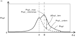
- Figure 9 shows an example of the change in the gas pressure Pcyl in the cylinder relative to the crank angle ⁇ d in a combustion cycle (compression stroke and combustion stroke) in which pre-ignition is occurring.
- the peak value Pcyl_max of the gas pressure in the cylinder is the gas pressure Pcyl in the cylinder at the position of the two-dot chain line B. Since the difference between the peak value Pcyl_max of the gas pressure in the cylinder in Figure 9 and Figure 8 is small, it becomes difficult to determine whether pre-ignition has occurred.
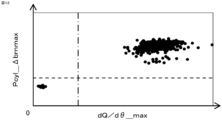
- Figure 10 plots the relationship between the peak value dQ/d ⁇ _max of the actual heat release rate and the gas pressure Pcyl_ ⁇ brnmax in the cylinder at the crank angle corresponding to the peak value of the increase in gas pressure in the cylinder due to combustion ⁇ Pcyl_brn in each combustion cycle when there is a mixture of combustion cycles in which pre-ignition occurs and combustion cycles in which pre-ignition does not occur.
- the peak value dQ/d ⁇ _max of the actual heat release rate is a value calculated from the actual gas pressure in the cylinder (for example, a value measured by a gas pressure sensor in the cylinder), and ⁇ Pcyl_brn and Pcyl_ ⁇ brnmax are values calculated by the control device 50.
- the gas pressure Pcyl_ ⁇ brnmax in the cylinder at the crank angle corresponding to the peak value of the increase in gas pressure in the cylinder due to combustion ⁇ Pcyl_brn is the gas pressure Pcyl in the cylinder at the position of the two-dot chain line B.
- Figure 11 plots the relationship between the crank angle ⁇ _dQ/d ⁇ max corresponding to the peak value dQ/d ⁇ _max of the actual heat release rate and the crank angle ⁇ d_ ⁇ brnmax corresponding to the peak value of the increase in gas pressure in the cylinder due to combustion ⁇ Pcyl_brn in each combustion cycle when there is a mixture of combustion cycles in which pre-ignition occurs and combustion cycles in which pre-ignition does not occur.
- the peak value dQ/d ⁇ _max of the actual heat release rate is a value calculated from the actual gas pressure in the cylinder (for example, a value measured by a gas pressure sensor in the cylinder), and the crank angle ⁇ d_ ⁇ brnmax corresponding to the peak value of the increase in gas pressure in the cylinder due to combustion ⁇ Pcyl_brn is a value calculated by the control device 50.
- crank angle ⁇ d_ ⁇ brnmax (above the dashed line in FIG. 11) corresponding to the peak value of ⁇ Pcyl_brn to the right of the dashed dotted line, which is the region of the crank angle ⁇ _dQ/d ⁇ max corresponding to the peak value of the actual heat release rate for which it is desired to determine that pre-ignition is occurring, and the crank angle ⁇ d_ ⁇ brnmax (below the dashed line in FIG.
- Figure 12 plots the relationship between the peak value dQ/d ⁇ _max of the actual heat release rate and the gas pressure Pcyl_ ⁇ brnmax in the cylinder at the crank angle corresponding to the peak value of the increase in gas pressure in the cylinder due to combustion ⁇ Pcyl_brn in each combustion cycle when there is a mixture of combustion cycles in which misfires occur and combustion cycles in which misfires do not occur. Note that the scales of the horizontal and vertical axes in Figure 12 are larger than those of the horizontal and vertical axes in Figure 10.
- the peak value dQ/d ⁇ _max of the actual heat release rate is a value calculated from the actual gas pressure in the cylinder (for example, a value measured by a gas pressure sensor in the cylinder), and ⁇ Pcyl_brn and Pcyl_ ⁇ brnmax are values calculated by the control device 50.
- Figure 13 plots the relationship between the crank angle ⁇ _dQ/d ⁇ max corresponding to the peak value dQ/d ⁇ _max of the actual heat release rate and the crank angle ⁇ d_ ⁇ brnmax corresponding to the peak value of the increase in gas pressure in the cylinder due to combustion ⁇ Pcyl_brn in each combustion cycle when there is a mixture of combustion cycles in which misfires occur and combustion cycles in which misfires do not occur. Note that the scales of the horizontal and vertical axes in Figure 13 are larger than those of the horizontal and vertical axes in Figure 11.
- the peak value dQ/d ⁇ _max of the actual heat release rate is a value calculated from the actual gas pressure in the cylinder (for example, a value measured by a gas pressure sensor in the cylinder), and the crank angle ⁇ d_ ⁇ brnmax corresponding to the peak value of the increase in gas pressure in the cylinder due to combustion ⁇ Pcyl_brn is a value calculated by the control device 50.
- crank angle ⁇ d_ ⁇ brnmax (below the dashed line in FIG. 13) corresponding to the peak value of ⁇ Pcyl_brn to the left of the dashed line, which is the region of the crank angle ⁇ _dQ/d ⁇ max corresponding to the peak value of the actual heat release rate for which it is desired to determine that a misfire is occurring, can be clearly separated from the crank angle ⁇ d_ ⁇ brnmax (above the dashed line in FIG.
- the occurrence of abnormal combustion such as pre-ignition and misfire can be determined by the increase in gas pressure in the cylinder due to combustion that has little angle dependency, ⁇ Pcyl_brn.
- the abnormal combustion determination unit 53 determines whether or not abnormal combustion has occurred in the internal combustion engine based on the increment ⁇ Pcyl_brn of gas pressure due to combustion at each crank angle ⁇ d in the determination angle interval ⁇ det set corresponding to the combustion period.
- the increase in gas pressure due to combustion ⁇ Pcyl_brn has little angle dependency and is a good indicator of the effects of abnormal combustion. Therefore, the presence or absence of abnormal combustion can be accurately determined based on the increase in gas pressure due to combustion ⁇ Pcyl_brn.
- the judgment angle interval ⁇ det is set to an angle interval within the compression stroke and the combustion stroke so that it can be determined whether or not abnormal combustion has occurred. Note that the compression stroke does not have to be included.
- the abnormal combustion judgment unit 53 judges the peak value of the increase in gas pressure due to combustion ⁇ Pcyl_brn in the judgment angle interval ⁇ det, and determines whether or not pre-ignition has occurred by comparing the gas pressure Pcyl_ ⁇ brnmax in the cylinder at the crank angle ⁇ d corresponding to the peak value with the gas pressure threshold value ThP_pre for pre-ignition.
- the abnormal combustion determination unit 53 determines that pre-ignition has occurred if the gas pressure Pcyl_ ⁇ brnmax in the cylinder corresponding to the peak value of ⁇ Pcyl_brn exceeds the gas pressure threshold value ThP_pre for pre-ignition, and determines that pre-ignition has not occurred if Pcyl_ ⁇ brnmax falls below the gas pressure threshold value ThP_pre for pre-ignition.
- the abnormal combustion determination unit 53 sets the gas pressure threshold value ThP_pre for pre-ignition based on the operating state of the internal combustion engine. For example, the abnormal combustion determination unit 53 references gas pressure threshold value data for pre-ignition in which the relationship between the operating state and the gas pressure threshold value ThP_pre is set, and sets the gas pressure threshold value ThP_pre for pre-ignition that corresponds to the current operating state.
- the operating state of the internal combustion engine may include the state of the amount of intake gas in the cylinder (e.g., the gas pressure Pin in the intake pipe, the amount of intake air, etc.), the air-fuel ratio, the rotational speed (rotational angular velocity), etc.
- the abnormal combustion determination unit 53 may determine the peak value of the increase in gas pressure due to combustion ⁇ Pcyl_brn in the determination angle interval ⁇ det, and compare the crank angle ⁇ d_ ⁇ brnmax corresponding to the peak value with the angle threshold value for pre-ignition Th ⁇ _pre to determine whether pre-ignition has occurred.
- the abnormal combustion determination unit 53 determines that pre-ignition has occurred if the crank angle ⁇ d_ ⁇ brnmax corresponding to the peak value of ⁇ Pcyl_brn exceeds the angle threshold value Th ⁇ _pre for pre-ignition, and determines that pre-ignition has not occurred if ⁇ d_ ⁇ brnmax falls below the angle threshold value Th ⁇ _pre for pre-ignition.
- the abnormal combustion determination unit 53 sets the angle threshold value Th ⁇ _pre for pre-ignition based on the operating state of the internal combustion engine. For example, the abnormal combustion determination unit 53 references gas pressure threshold data for pre-ignition in which the relationship between the operating state and the angle threshold value Th ⁇ _pre is set, and sets the angle threshold value Th ⁇ _pre for pre-ignition that corresponds to the current operating state.
- the operating state of the internal combustion engine may include the state of the amount of intake gas in the cylinder (e.g., the gas pressure Pin in the intake pipe, the amount of intake air, etc.), the air-fuel ratio, the rotational speed (rotational angular velocity), etc.
- the abnormal combustion judgment unit 53 judges the peak value of the increase in gas pressure due to combustion ⁇ Pcyl_brn in the judgment angle range ⁇ det, and judges whether or not a misfire has occurred by comparing the gas pressure Pcyl_ ⁇ brnmax in the cylinder at the crank angle corresponding to the peak value with the gas pressure threshold value ThP_mf for misfire.
- the abnormal combustion determination unit 53 determines that a misfire has occurred if the gas pressure Pcyl_ ⁇ brnmax in the cylinder corresponding to the peak value of ⁇ Pcyl_brn falls below the gas pressure threshold ThP_mf for misfire, and determines that a misfire has not occurred if Pcyl_ ⁇ brnmax exceeds the gas pressure threshold ThP_mf for misfire.
- the abnormal combustion determination unit 53 sets the gas pressure threshold value ThP_mf for misfire based on the operating state of the internal combustion engine. For example, the abnormal combustion determination unit 53 references gas pressure threshold value data for misfire in which the relationship between the operating state and the gas pressure threshold value ThP_mf is set, and sets the gas pressure threshold value ThP_mf that corresponds to the current operating state.
- the operating state of the internal combustion engine may include the state of the amount of intake gas in the cylinder (e.g., the gas pressure Pin in the intake pipe, the amount of intake air, etc.), the air-fuel ratio, the rotational speed (rotational angular velocity), etc.
- the abnormal combustion determination unit 53 may determine the peak value of the increase in gas pressure due to combustion ⁇ Pcyl_brn in the determination angle interval ⁇ det, and compare the crank angle ⁇ d_ ⁇ brnmax corresponding to the peak value with the angle threshold value for misfire Th ⁇ _mf to determine whether or not a misfire has occurred.
- the abnormal combustion determination unit 53 determines that a misfire has occurred if the crank angle ⁇ d_ ⁇ brnmax corresponding to the peak value of ⁇ Pcyl_brn falls below the angle threshold value Th ⁇ _mf for misfire, and determines that a misfire has not occurred if ⁇ d_ ⁇ brnmax exceeds the angle threshold value Th ⁇ _mf for misfire.
- the abnormal combustion determination unit 53 sets the angle threshold Th ⁇ _mf for misfire based on the operating state of the internal combustion engine. For example, the abnormal combustion determination unit 53 references gas pressure threshold data for misfire in which the relationship between the operating state and the angle threshold Th ⁇ _mf is set, and sets the angle threshold Th ⁇ _mf for misfire that corresponds to the current operating state.
- the operating state of the internal combustion engine may include the state of the amount of intake gas in the cylinder (e.g., the gas pressure Pin in the intake pipe, the amount of intake air, etc.), the air-fuel ratio, the rotational speed (rotational angular velocity), etc.
- ⁇ Calculation of Peak Value of ⁇ Pcyl_brn Taking Misfire into Account> 14 shows an example of changes in the gas pressure Pcyl in the cylinder relative to the crank angle ⁇ d in a combustion cycle (compression stroke and combustion stroke) in which a misfire occurs.
- the increase ⁇ Pcyl_brn in the gas pressure in the cylinder due to combustion becomes close to 0, making it difficult to determine its peak value, and the crank angle ⁇ d_ ⁇ brnmax corresponding to the peak value fluctuates for each combustion cycle, making it easy for errors in misfire determination to occur.
- the abnormal combustion determination unit 53 therefore determines the peak value of the increase in gas pressure due to combustion ⁇ Pcyl_brn in the determination angle interval ⁇ det, and if the peak value is smaller than the misfire state corresponding threshold Th ⁇ P_mf, sets the angle ⁇ d_mf corresponding to the misfire state, which is preset within the determination angle interval ⁇ det, as the crank angle ⁇ d_ ⁇ brnmax corresponding to the peak value.
- the angle ⁇ d_mf corresponding to the misfire state can be set as the crank angle ⁇ d_ ⁇ brnmax corresponding to the peak value, and ⁇ d_ ⁇ brnmax can be prevented from fluctuating with each combustion cycle, thereby suppressing the occurrence of errors in misfire determination.
- the misfire state corresponding threshold value Th ⁇ P_mf is set to a value greater than 0, taking into consideration the fluctuation range of ⁇ Pcyl_brn due to noise, variation factors, etc., when a misfire occurs.
- the misfire state corresponding angle ⁇ d_mf is set to the end angle of the judgment angle interval ⁇ det, or is preset to correspond to the crank angle ⁇ d_ ⁇ brnmax that corresponds to the peak value when no misfire occurs.
- ⁇ Measures to deal with fluctuations in ⁇ Pcyl_brn> 15 is an example of changes in the gas pressure Pcyl in the cylinder with respect to the crank angle ⁇ d in a combustion cycle (compression stroke and combustion stroke) in which no misfire occurs.
- the increase in gas pressure in the cylinder due to combustion ⁇ Pcyl_brn is greater than 0 before the start of combustion (hatched portion).
- the gas pressure calculation unit 52 determines the crank angle ⁇ d at which the increase in gas pressure due to combustion ⁇ Pcyl_brn becomes greater than the zero-over-zero determination threshold Th ⁇ P_0 for the first time during the compression stroke as the first crank angle ⁇ d1, determines the crank angle ⁇ d at which the increase in gas pressure due to combustion ⁇ Pcyl_brn becomes equal to or less than the zero-over-zero determination threshold Th ⁇ P_0 after the first crank angle ⁇ d1 as the second crank angle ⁇ d2, and determines the crank angle ⁇ d at which the increase in gas pressure due to combustion ⁇ Pcyl_brn becomes greater than the zero-over-zero determination threshold Th ⁇ P_0 after the second crank angle ⁇ d2 in the combustion stroke following the compression stroke as the third crank angle ⁇ d3.
- the gas pressure calculation unit 52 sets the increase in gas pressure due to combustion ⁇ Pcyl_brn in the angle section corresponding to the first crank angle ⁇ d1 to the second crank angle ⁇ d2 to 0.
- the zero excess determination threshold value Th ⁇ P_0 is set to a value equal to or greater than 0.
- Avoidance control unit 54 When the abnormal combustion determination unit 53 determines that abnormal combustion has occurred, the avoidance control unit 54 changes control parameters of the internal combustion engine to suppress the occurrence of abnormal combustion, and controls the internal combustion engine.
- the control parameters to be changed include one or more of the fuel injection amount, the amount of intake gas in the cylinder, the ignition timing, the EGR amount, and the control amount of the variable valve timing mechanism.
- the avoidance control unit 54 when it is determined that pre-ignition has occurred, enriches (increases) the fuel injection amount from the reference injection amount, and suppresses the occurrence of pre-ignition by cooling the fuel.
- the avoidance control unit 54 when it is determined that pre-ignition has occurred, reduces the intake gas amount in the cylinder to less than the reference intake gas amount, and suppresses the occurrence of pre-ignition by reducing the temperature of the compressed gas near the top dead center.
- the throttle valve 4 is controlled to the closing side.
- the avoidance control unit 54 when it is determined that pre-ignition has occurred, changes the ignition timing to the retard side from the reference ignition timing, and suppresses the occurrence of pre-ignition by reducing the combustion temperature.
- the avoidance control unit 54 increases the EGR amount above the reference EGR amount when it is determined that pre-ignition has occurred, thereby suppressing the occurrence of pre-ignition by reducing the ignitability of the mixture and reducing the combustion temperature. For example, the EGR valve 22 is controlled to the open side. If the control parameters to be changed include the control amount of the variable valve timing mechanism, the avoidance control unit 54 changes the control amount of the variable valve timing mechanism to a side that suppresses the occurrence of pre-ignition more than the reference control amount when it is determined that pre-ignition has occurred, thereby suppressing the occurrence of pre-ignition.
- the control amount of the variable valve timing mechanism becomes the opening and closing timing of the exhaust valve when controlling the variable valve timing mechanism of the exhaust valve, and becomes the opening and closing timing of the intake valve when controlling the variable valve timing mechanism of the intake valve.
- the control amount is changed so that the overlap period between the opening period of the exhaust valve and the opening period of the intake valve increases, the internal EGR amount is increased, and the occurrence of pre-ignition is suppressed by reducing the ignitability of the mixture and reducing the combustion temperature.
- the avoidance control unit 54 changes the reference control parameters calculated by the basic control unit 55 for the control parameters to be changed, transmits the changed control parameters to the basic control unit 55, and reflects them in the control of the basic control unit 55. If it is determined that pre-ignition has occurred, the avoidance control unit 54 gradually changes the control parameters to be changed to the side that suppresses the occurrence of pre-ignition, and if it is determined that pre-ignition has not occurred, gradually returns the control parameters to the opposite side from the side that suppresses the occurrence of pre-ignition.
- the avoidance control unit 54 may increase the amount of change in the control parameters to be changed to the side that suppresses the occurrence of pre-ignition as the intensity of the occurrence of pre-ignition increases. If the control parameters to be changed can be changed for each cylinder, the control parameters to be changed for the cylinder in which pre-ignition has occurred may be changed.
- the avoidance control unit 54 makes the fuel injection amount richer (increases it) than the reference injection amount when it is determined that a misfire has occurred, thereby suppressing the occurrence of a misfire. If the control parameters to be changed include the intake gas amount in the cylinder, the avoidance control unit 54 increases the intake gas amount in the cylinder to more than the reference intake gas amount when it is determined that a misfire has occurred, thereby suppressing the occurrence of a misfire. For example, the throttle valve 4 is controlled to open. If the control parameters to be changed include the ignition timing, the avoidance control unit 54 changes the ignition timing to the advanced side from the reference ignition timing when it is determined that a misfire has occurred, thereby suppressing the occurrence of a misfire.
- the avoidance control unit 54 reduces the EGR amount below the reference EGR amount when it is determined that a misfire has occurred, thereby suppressing the occurrence of a misfire. For example, it controls the EGR valve 22 to the closing side. If the control parameters to be changed include the control amount of the variable valve timing mechanism, the avoidance control unit 54 changes the control amount of the variable valve timing mechanism to a side that suppresses the occurrence of a misfire more than the reference control amount when it is determined that a misfire has occurred, thereby suppressing the occurrence of a misfire.
- the control amount of the variable valve timing mechanism becomes the exhaust valve opening and closing timing when controlling the variable valve timing mechanism of the exhaust valve, and becomes the intake valve opening and closing timing when controlling the variable valve timing mechanism of the intake valve. For example, it changes the control amount so that the overlap period between the exhaust valve opening period and the intake valve opening period is reduced, thereby reducing the internal EGR amount and suppressing the occurrence of a misfire.
- the avoidance control unit 54 changes the reference control parameters calculated by the basic control unit 55 for the control parameters to be changed, transmits the changed control parameters to the basic control unit 55, and reflects them in the control of the basic control unit 55. If it is determined that a misfire has occurred, the avoidance control unit 54 gradually changes the control parameters to be changed to the side that suppresses the occurrence of misfire, and if it is determined that a misfire has not occurred, gradually returns the control parameters to the side opposite to the suppression side. Furthermore, the avoidance control unit 54 may increase the amount of change in the control parameters to be changed to the side that suppresses the occurrence of misfire as the frequency of misfire increases. If the control parameters to be changed can be changed for each cylinder, the control parameters to be changed for the cylinder where a misfire has occurred may be changed.
- control device 50 according to a second embodiment will be described with reference to the drawings. Description of components similar to those of the first embodiment will be omitted.
- the basic configuration of the control device 50 according to this embodiment is similar to that of the first embodiment.
- This embodiment differs from the first embodiment in that a gas pressure calculation unit 52 calculates the heat release rate dQ/d ⁇ d, and an abnormal combustion determination unit 53 uses the heat release rate dQ/d ⁇ d to determine whether or not abnormal combustion has occurred.
- a gas pressure calculation unit 52 calculates a heat generation rate dQ/d ⁇ d per unit crank angle at each crank angle ⁇ d based on the gas pressure Pcyl in the cylinder and the crank angle ⁇ d.
- the gas pressure calculation unit 52 calculates the heat release rate dQ/d ⁇ d per unit crank angle at each crank angle ⁇ d using the following equation.
- ⁇ is the specific heat ratio
- Vcly_ ⁇ is the cylinder volume of the combustion cylinder at each crank angle ⁇ d, and is calculated as described above using equation (3).
- the calculated heat release rate dQ/d ⁇ d for each crank angle ⁇ d is stored in a storage device 91 such as a RAM, like other calculated values.
- crank angle ⁇ d_dQ/d ⁇ dmax (above the dashed line in FIG. 16) corresponding to the peak value of the heat release rate to the right of the dashed dotted line, which is the region of the crank angle ⁇ _dQ/d ⁇ max corresponding to the peak value of the actual heat release rate for which it is desired to determine that pre-ignition is occurring, and the crank angle ⁇ d_dQ/d ⁇ dmax (below the dashed line in FIG.
- the relationship between the crank angle ⁇ _dQ/d ⁇ max corresponding to the peak value dQ/d ⁇ _max of the actual heat release rate and the crank angle ⁇ d_dQ/d ⁇ dmax corresponding to the peak value dQ/d ⁇ d_max of the heat release rate calculated by the control device 50 is plotted in each combustion cycle when there is a mixture of combustion cycles in which misfires occur and combustion cycles in which misfires do not occur.
- the scales of the horizontal and vertical axes in FIG. 17 are larger than those of the horizontal and vertical axes in FIG. 16.
- the peak value dQ/d ⁇ _max of the actual heat release rate is a value calculated from the actual gas pressure in the cylinder (for example, a value measured by a gas pressure sensor in the cylinder).
- crank angle ⁇ d_dQ/d ⁇ dmax (below the dashed line in FIG. 17) corresponding to the peak value of the heat release rate to the left of the dashed line, which is the region of the crank angle ⁇ _dQ/d ⁇ max corresponding to the peak value of the actual heat release rate for which it is desired to determine that a misfire is occurring, from the crank angle ⁇ d_dQ/d ⁇ dmax (above the dashed line in FIG. 17) corresponding to the peak value of the heat release rate to the right of the dashed line, which is the region of the crank angle ⁇ _dQ/d ⁇ max corresponding to the peak value of the actual heat release rate for which it is desired to determine that a misfire is not occurring.
- the occurrence of abnormal combustion such as pre-ignition and misfire can be determined by the heat release rate dQ/d ⁇ d, which has little angle dependency.
- the abnormal combustion judgment unit 53 judges whether or not abnormal combustion has occurred in the internal combustion engine based on the heat generation rate dQ/d ⁇ d at each crank angle ⁇ d in the judgment angle range ⁇ det, which is calculated based on the increase in gas pressure ⁇ Pcyl_brn due to combustion at each crank angle ⁇ d.
- the heat release rate dQ/d ⁇ d has little angle dependency and is highly sensitive to the effects of abnormal combustion. Therefore, the presence or absence of abnormal combustion can be accurately determined based on the heat release rate dQ/d ⁇ d calculated based on the increase in gas pressure due to combustion ⁇ Pcyl_brn.
- the abnormal combustion judgment unit 53 judges the peak value of the heat generation rate dQ/d ⁇ d in the judgment angle interval ⁇ det, and determines whether or not pre-ignition has occurred by comparing the crank angle ⁇ d_dQ/d ⁇ dmax corresponding to the peak value with the angle threshold value Th ⁇ _pre for pre-ignition.
- the abnormal combustion determination unit 53 determines that pre-ignition has occurred if the crank angle ⁇ d_dQ/d ⁇ dmax corresponding to the peak value of dQ/d ⁇ d exceeds the angle threshold value Th ⁇ _pre for pre-ignition, and determines that pre-ignition has not occurred if ⁇ d_dQ/d ⁇ dmax falls below the angle threshold value Th ⁇ _pre for pre-ignition.
- the abnormal combustion determination unit 53 sets the angle threshold value Th ⁇ _pre for pre-ignition based on the operating state of the internal combustion engine. For example, the abnormal combustion determination unit 53 references gas pressure threshold data for pre-ignition in which the relationship between the operating state and the angle threshold value Th ⁇ _pre is set, and sets the angle threshold value Th ⁇ _pre for pre-ignition that corresponds to the current operating state.
- the operating state of the internal combustion engine may include the state of the amount of intake gas in the cylinder (e.g., the gas pressure Pin in the intake pipe, the amount of intake air, etc.), the air-fuel ratio, the rotational speed (rotational angular velocity), etc.
- the abnormal combustion judgment unit 53 judges the peak value of the heat release rate dQ/d ⁇ d in the judgment angle range ⁇ det, and judges whether or not a misfire has occurred by comparing the crank angle ⁇ d_dQ/d ⁇ dmax corresponding to the peak value with the angle threshold value Th ⁇ _mf for misfire.
- the abnormal combustion determination unit 53 determines that a misfire has occurred if the crank angle ⁇ d_dQ/d ⁇ dmax corresponding to the peak value of the heat release rate dQ/d ⁇ d falls below the angle threshold value Th ⁇ _mf for misfire, and determines that a misfire has not occurred if ⁇ d_dQ/d ⁇ dmax exceeds the angle threshold value Th ⁇ _mf for misfire.
- the abnormal combustion determination unit 53 sets the angle threshold Th ⁇ _mf for misfire based on the operating state of the internal combustion engine. For example, the abnormal combustion determination unit 53 references gas pressure threshold data for misfire in which the relationship between the operating state and the angle threshold Th ⁇ _mf is set, and sets the angle threshold Th ⁇ _mf for misfire that corresponds to the current operating state.
- the operating state of the internal combustion engine may include the state of the amount of intake gas in the cylinder (e.g., the gas pressure Pin in the intake pipe, the amount of intake air, etc.), the air-fuel ratio, the rotational speed (rotational angular velocity), etc.
- the abnormal combustion judgment unit 53 judges the peak value of the heat release rate dQ/d ⁇ d in the judgment angle interval ⁇ det, and if the peak value is smaller than the misfire state corresponding threshold value ThdQ_mf, sets the angle ⁇ d_mf corresponding to the misfire state that is preset within the judgment angle interval ⁇ det as the crank angle ⁇ d_dQ/d ⁇ dmax corresponding to the peak value.
- the angle ⁇ d_mf corresponding to the misfire state can be set as the crank angle ⁇ d_dQ/d ⁇ dmax corresponding to the peak value, and ⁇ d_dQ/d ⁇ dmax can be prevented from fluctuating with each combustion cycle, thereby suppressing the occurrence of errors in misfire determination.
- control device 50 according to a third embodiment will be described with reference to the drawings. Descriptions of components similar to those of the first embodiment will be omitted.
- the basic configuration of the control device 50 according to this embodiment is similar to that of the first embodiment.
- This embodiment differs from the first embodiment in that a gas pressure calculation unit 52 calculates the heat release rate dQ/d ⁇ d and the mass fraction burned MFB, and an abnormal combustion determination unit 53 uses the mass fraction burned MFB to determine whether or not abnormal combustion has occurred.
- the gas pressure calculation unit 52 calculates the heat release rate dQ/d ⁇ d per unit crank angle at each crank angle ⁇ d based on the gas pressure Pcyl in the cylinder and the crank angle ⁇ d.
- the gas pressure calculation unit 52 uses equation (12) to calculate the heat generation rate dQ/d ⁇ d per unit crank angle at each crank angle ⁇ d.
- the gas pressure calculation unit 52 calculates the mass fraction burned MFB for each crank angle ⁇ d by integrating the heat release rate dQ/d ⁇ d during the combustion period.
- the gas pressure calculation unit 52 uses the following equation to calculate the mass fraction burned MFB for each crank angle ⁇ d by dividing an interval integral value obtained by integrating the heat release rate dQ/d ⁇ d from the start angle ⁇ 0 to each crank angle ⁇ d by a total integral value Q0 obtained by integrating the heat release rate dQ/d ⁇ d over the entire combustion period.
- the gas pressure calculation unit 52 performs a calculation process to calculate the mass fraction burned MFB at each crank angle ⁇ d.
- the calculated mass fraction burned MFB for each crank angle ⁇ d is stored in the storage device 91, such as a RAM, like other calculated values.
- the peak value dQ/d ⁇ _max of the actual heat release rate is a value calculated from the actual gas pressure in the cylinder (for example, a value measured by a gas pressure sensor in the cylinder).
- crank angle ⁇ d_MFB90 (above the dashed line in FIG. 18) at which the mass burn fraction MFB reaches the determination percentage (90%) on the right side of the dashed line, which is the region of the crank angle ⁇ _dQ/d ⁇ max corresponding to the peak value of the actual heat release rate at which it is desired to determine that pre-ignition is occurring, and the crank angle ⁇ d_MFB90 (below the dashed line in FIG.
- Figure 19 plots the relationship between the crank angle ⁇ _dQ/d ⁇ max corresponding to the peak value dQ/d ⁇ _max of the actual heat release rate in each combustion cycle, and the crank angle ⁇ d_MFB90 at which the mass fraction burned MFB calculated by the control device 50 reaches the judgment rate (90%) when there is a mixture of combustion cycles in which misfires occur and combustion cycles in which misfires do not occur.
- the scales of the horizontal and vertical axes in Figure 19 are larger than those of the horizontal and vertical axes in Figure 18.
- the peak value dQ/d ⁇ _max of the actual heat release rate is a value calculated from the actual gas pressure in the cylinder (for example, a value measured by a gas pressure sensor in the cylinder).
- crank angle ⁇ d_MFB90 (below the dashed line in FIG. 19) at which the mass fraction burned MFB reaches the determination percentage (90%) on the left side of the dashed line, which is the region of the crank angle ⁇ _dQ/d ⁇ max corresponding to the peak value of the actual heat release rate at which it is desired to determine that a misfire is occurring, can be clearly separated from the crank angle ⁇ d_MFB90 (above the dashed line in FIG.
- the occurrence of abnormal combustion such as pre-ignition and misfire can be determined by the mass fraction burned (MFB), which has little angle dependency.
- the abnormal combustion judgment unit 53 judges whether or not abnormal combustion has occurred in the internal combustion engine based on the mass combustion fraction MFB at each crank angle ⁇ d in the judgment angle range ⁇ det, which is calculated based on the increase ⁇ Pcyl_brn in gas pressure due to combustion at each crank angle ⁇ d.
- the mass fraction burned MFB has little angle dependency and is more susceptible to the effects of abnormal combustion. Therefore, the presence or absence of abnormal combustion can be accurately determined based on the mass fraction burned MFB calculated based on the increase in gas pressure due to combustion ⁇ Pcyl_brn.
- the abnormal combustion determination unit 53 determines the crank angle ⁇ d_MFB90 at which the mass fraction burned MFB becomes a determination ratio (e.g., 90%) in the determination angle section ⁇ det, and compares the crank angle ⁇ d_MFB90 corresponding to the determination ratio with the angle threshold value Th ⁇ _pre for pre-ignition to determine whether or not pre-ignition has occurred.
- the determination ratio may be set to a ratio other than 90%.
- the abnormal combustion determination unit 53 determines that pre-ignition has occurred if the crank angle ⁇ d_MFB90 at which the mass burn fraction MFB becomes the determination ratio (90%) exceeds the angle threshold value Th ⁇ _pre for pre-ignition, and determines that pre-ignition has not occurred if ⁇ d_MFB90 falls below the angle threshold value Th ⁇ _pre for pre-ignition.
- the abnormal combustion determination unit 53 sets the angle threshold value Th ⁇ _pre for pre-ignition based on the operating state of the internal combustion engine. For example, the abnormal combustion determination unit 53 references gas pressure threshold data for pre-ignition in which the relationship between the operating state and the angle threshold value Th ⁇ _pre is set, and sets the angle threshold value Th ⁇ _pre for pre-ignition that corresponds to the current operating state.
- the operating state of the internal combustion engine may include the state of the amount of intake gas in the cylinder (e.g., the gas pressure Pin in the intake pipe, the amount of intake air, etc.), the air-fuel ratio, the rotational speed (rotational angular velocity), etc.
- the abnormal combustion judgment unit 53 judges the crank angle ⁇ d_MFB90 at which the mass burned fraction MFB becomes a judgment ratio (e.g., 90%) in the judgment angle range ⁇ det, and judges whether or not a misfire has occurred by comparing the crank angle ⁇ d_MFB90 corresponding to the judgment ratio with the angle threshold value Th ⁇ _mf for misfire.
- a judgment ratio e.g. 90%
- the abnormal combustion determination unit 53 determines that a misfire has occurred if the crank angle ⁇ d_MFB90 at which the mass fraction burned MFB becomes the determination ratio (90%) falls below the misfire angle threshold Th ⁇ _mf, and determines that a misfire has not occurred if ⁇ d_MFB90 exceeds the misfire angle threshold Th ⁇ _mf.
- the abnormal combustion determination unit 53 sets the angle threshold Th ⁇ _mf for misfire based on the operating state of the internal combustion engine. For example, the abnormal combustion determination unit 53 references gas pressure threshold data for misfire in which the relationship between the operating state and the angle threshold Th ⁇ _mf is set, and sets the angle threshold Th ⁇ _mf for misfire that corresponds to the current operating state.
- the operating state of the internal combustion engine may include the state of the amount of intake gas in the cylinder (e.g., the gas pressure Pin in the intake pipe, the amount of intake air, etc.), the air-fuel ratio, the rotational speed (rotational angular velocity), etc.
- the angle information detection unit 51 uses the output signal of the crank angle sensor 11.
- another crank angle sensor that detects the teeth of a link gear or the like may be provided, and the angle information detection unit 51 may use the output signal of the other crank angle sensor.
- a three-cylinder engine is used as an example.
- an engine with any number of cylinders e.g., one, two, four, or six cylinders may be used.
Landscapes
- Engineering & Computer Science (AREA)
- Chemical & Material Sciences (AREA)
- Combustion & Propulsion (AREA)
- Mechanical Engineering (AREA)
- General Engineering & Computer Science (AREA)
- Combined Controls Of Internal Combustion Engines (AREA)
Priority Applications (2)
| Application Number | Priority Date | Filing Date | Title |
|---|---|---|---|
| JP2025516366A JP7814617B2 (ja) | 2023-04-26 | 2023-04-26 | 内燃機関の制御装置 |
| PCT/JP2023/016400 WO2024224500A1 (ja) | 2023-04-26 | 2023-04-26 | 内燃機関の制御装置 |
Applications Claiming Priority (1)
| Application Number | Priority Date | Filing Date | Title |
|---|---|---|---|
| PCT/JP2023/016400 WO2024224500A1 (ja) | 2023-04-26 | 2023-04-26 | 内燃機関の制御装置 |
Publications (1)
| Publication Number | Publication Date |
|---|---|
| WO2024224500A1 true WO2024224500A1 (ja) | 2024-10-31 |
Family
ID=93256125
Family Applications (1)
| Application Number | Title | Priority Date | Filing Date |
|---|---|---|---|
| PCT/JP2023/016400 Ceased WO2024224500A1 (ja) | 2023-04-26 | 2023-04-26 | 内燃機関の制御装置 |
Country Status (2)
| Country | Link |
|---|---|
| JP (1) | JP7814617B2 (https=) |
| WO (1) | WO2024224500A1 (https=) |
Citations (5)
| Publication number | Priority date | Publication date | Assignee | Title |
|---|---|---|---|---|
| JPH02136566A (ja) * | 1988-07-01 | 1990-05-25 | Honda Motor Co Ltd | 内燃エンジンの異常燃焼検知装置及び燃焼制御装置 |
| JPH09317550A (ja) * | 1996-05-24 | 1997-12-09 | Tokyo Gas Co Ltd | 内燃機関の燃焼状態の判定方法及び装置 |
| JP2010190174A (ja) * | 2009-02-20 | 2010-09-02 | Hitachi Automotive Systems Ltd | 内燃機関の燃焼トルク推定装置 |
| JP2022164167A (ja) * | 2021-04-16 | 2022-10-27 | 三菱電機株式会社 | 内燃機関の制御装置及び制御方法 |
| JP7246548B1 (ja) * | 2022-04-19 | 2023-03-27 | 三菱電機株式会社 | 内燃機関の制御装置 |
-
2023
- 2023-04-26 WO PCT/JP2023/016400 patent/WO2024224500A1/ja not_active Ceased
- 2023-04-26 JP JP2025516366A patent/JP7814617B2/ja active Active
Patent Citations (5)
| Publication number | Priority date | Publication date | Assignee | Title |
|---|---|---|---|---|
| JPH02136566A (ja) * | 1988-07-01 | 1990-05-25 | Honda Motor Co Ltd | 内燃エンジンの異常燃焼検知装置及び燃焼制御装置 |
| JPH09317550A (ja) * | 1996-05-24 | 1997-12-09 | Tokyo Gas Co Ltd | 内燃機関の燃焼状態の判定方法及び装置 |
| JP2010190174A (ja) * | 2009-02-20 | 2010-09-02 | Hitachi Automotive Systems Ltd | 内燃機関の燃焼トルク推定装置 |
| JP2022164167A (ja) * | 2021-04-16 | 2022-10-27 | 三菱電機株式会社 | 内燃機関の制御装置及び制御方法 |
| JP7246548B1 (ja) * | 2022-04-19 | 2023-03-27 | 三菱電機株式会社 | 内燃機関の制御装置 |
Also Published As
| Publication number | Publication date |
|---|---|
| JPWO2024224500A1 (https=) | 2024-10-31 |
| JP7814617B2 (ja) | 2026-02-16 |
Similar Documents
| Publication | Publication Date | Title |
|---|---|---|
| US11473517B1 (en) | Controller and control method for internal combustion engine | |
| JP7146131B1 (ja) | 内燃機関の制御装置 | |
| US11480121B2 (en) | Controller and control method for internal combustion engine | |
| US11555462B2 (en) | Controller and control method for internal combustion engine | |
| JP7246548B1 (ja) | 内燃機関の制御装置 | |
| JP7030884B2 (ja) | 内燃機関の制御装置 | |
| US11703418B2 (en) | Controller for internal combustion engine | |
| JP7814617B2 (ja) | 内燃機関の制御装置 | |
| JP2019183786A (ja) | 内燃機関の制御装置及び制御方法 | |
| JP7191187B1 (ja) | 内燃機関の制御装置 | |
| JP7621562B2 (ja) | 内燃機関のトルク推定装置 | |
| JP7250067B2 (ja) | 内燃機関の制御装置 | |
| WO2025197019A1 (ja) | 内燃機関の制御装置 | |
| JP7756839B2 (ja) | 内燃機関の制御装置 | |
| WO2025187039A1 (ja) | 内燃機関の制御装置 | |
| JP7191188B1 (ja) | 内燃機関の制御装置 | |
| WO2025182061A1 (ja) | 内燃機関の制御装置 | |
| WO2025182062A1 (ja) | 内燃機関の制御装置 | |
| JP2018071355A (ja) | 内燃機関のクランク角算出装置 |
Legal Events
| Date | Code | Title | Description |
|---|---|---|---|
| 121 | Ep: the epo has been informed by wipo that ep was designated in this application |
Ref document number: 23935280 Country of ref document: EP Kind code of ref document: A1 |
|
| WWE | Wipo information: entry into national phase |
Ref document number: 2025516366 Country of ref document: JP |
|
| NENP | Non-entry into the national phase |
Ref country code: DE |
|
| 122 | Ep: pct application non-entry in european phase |
Ref document number: 23935280 Country of ref document: EP Kind code of ref document: A1 |