WO2024219322A1 - 冷却システム - Google Patents
冷却システム Download PDFInfo
- Publication number
- WO2024219322A1 WO2024219322A1 PCT/JP2024/014760 JP2024014760W WO2024219322A1 WO 2024219322 A1 WO2024219322 A1 WO 2024219322A1 JP 2024014760 W JP2024014760 W JP 2024014760W WO 2024219322 A1 WO2024219322 A1 WO 2024219322A1
- Authority
- WO
- WIPO (PCT)
- Prior art keywords
- refrigerant
- refrigerant flow
- flow path
- gas
- control valve
- Prior art date
- Legal status (The legal status is an assumption and is not a legal conclusion. Google has not performed a legal analysis and makes no representation as to the accuracy of the status listed.)
- Ceased
Links
Images


Classifications
-
- F—MECHANICAL ENGINEERING; LIGHTING; HEATING; WEAPONS; BLASTING
- F28—HEAT EXCHANGE IN GENERAL
- F28D—HEAT-EXCHANGE APPARATUS, NOT PROVIDED FOR IN ANOTHER SUBCLASS, IN WHICH THE HEAT-EXCHANGE MEDIA DO NOT COME INTO DIRECT CONTACT
- F28D15/00—Heat-exchange apparatus with the intermediate heat-transfer medium in closed tubes passing into or through the conduit walls ; Heat-exchange apparatus employing intermediate heat-transfer medium or bodies
- F28D15/02—Heat-exchange apparatus with the intermediate heat-transfer medium in closed tubes passing into or through the conduit walls ; Heat-exchange apparatus employing intermediate heat-transfer medium or bodies in which the medium condenses and evaporates, e.g. heat pipes
- F28D15/06—Control arrangements therefor
-
- C—CHEMISTRY; METALLURGY
- C09—DYES; PAINTS; POLISHES; NATURAL RESINS; ADHESIVES; COMPOSITIONS NOT OTHERWISE PROVIDED FOR; APPLICATIONS OF MATERIALS NOT OTHERWISE PROVIDED FOR
- C09K—MATERIALS FOR MISCELLANEOUS APPLICATIONS, NOT PROVIDED FOR ELSEWHERE
- C09K5/00—Heat-transfer, heat-exchange or heat-storage materials, e.g. refrigerants; Materials for the production of heat or cold by chemical reactions other than by combustion
- C09K5/02—Materials undergoing a change of physical state when used
- C09K5/04—Materials undergoing a change of physical state when used the change of state being from liquid to vapour or vice versa
- C09K5/041—Materials undergoing a change of physical state when used the change of state being from liquid to vapour or vice versa for compression-type refrigeration systems
- C09K5/044—Materials undergoing a change of physical state when used the change of state being from liquid to vapour or vice versa for compression-type refrigeration systems comprising halogenated compounds
- C09K5/045—Materials undergoing a change of physical state when used the change of state being from liquid to vapour or vice versa for compression-type refrigeration systems comprising halogenated compounds containing only fluorine as halogen
-
- F—MECHANICAL ENGINEERING; LIGHTING; HEATING; WEAPONS; BLASTING
- F25—REFRIGERATION OR COOLING; COMBINED HEATING AND REFRIGERATION SYSTEMS; HEAT PUMP SYSTEMS; MANUFACTURE OR STORAGE OF ICE; LIQUEFACTION SOLIDIFICATION OF GASES
- F25B—REFRIGERATION MACHINES, PLANTS OR SYSTEMS; COMBINED HEATING AND REFRIGERATION SYSTEMS; HEAT PUMP SYSTEMS
- F25B1/00—Compression machines, plants or systems with non-reversible cycle
-
- F—MECHANICAL ENGINEERING; LIGHTING; HEATING; WEAPONS; BLASTING
- F25—REFRIGERATION OR COOLING; COMBINED HEATING AND REFRIGERATION SYSTEMS; HEAT PUMP SYSTEMS; MANUFACTURE OR STORAGE OF ICE; LIQUEFACTION SOLIDIFICATION OF GASES
- F25B—REFRIGERATION MACHINES, PLANTS OR SYSTEMS; COMBINED HEATING AND REFRIGERATION SYSTEMS; HEAT PUMP SYSTEMS
- F25B39/00—Evaporators; Condensers
- F25B39/02—Evaporators
-
- F—MECHANICAL ENGINEERING; LIGHTING; HEATING; WEAPONS; BLASTING
- F25—REFRIGERATION OR COOLING; COMBINED HEATING AND REFRIGERATION SYSTEMS; HEAT PUMP SYSTEMS; MANUFACTURE OR STORAGE OF ICE; LIQUEFACTION SOLIDIFICATION OF GASES
- F25B—REFRIGERATION MACHINES, PLANTS OR SYSTEMS; COMBINED HEATING AND REFRIGERATION SYSTEMS; HEAT PUMP SYSTEMS
- F25B41/00—Fluid-circulation arrangements
- F25B41/20—Disposition of valves, e.g. of on-off valves or flow control valves
-
- F—MECHANICAL ENGINEERING; LIGHTING; HEATING; WEAPONS; BLASTING
- F25—REFRIGERATION OR COOLING; COMBINED HEATING AND REFRIGERATION SYSTEMS; HEAT PUMP SYSTEMS; MANUFACTURE OR STORAGE OF ICE; LIQUEFACTION SOLIDIFICATION OF GASES
- F25B—REFRIGERATION MACHINES, PLANTS OR SYSTEMS; COMBINED HEATING AND REFRIGERATION SYSTEMS; HEAT PUMP SYSTEMS
- F25B43/00—Arrangements for separating or purifying gases or liquids; Arrangements for vaporising the residuum of liquid refrigerant, e.g. by heat
- F25B43/006—Accumulators
-
- F—MECHANICAL ENGINEERING; LIGHTING; HEATING; WEAPONS; BLASTING
- F25—REFRIGERATION OR COOLING; COMBINED HEATING AND REFRIGERATION SYSTEMS; HEAT PUMP SYSTEMS; MANUFACTURE OR STORAGE OF ICE; LIQUEFACTION SOLIDIFICATION OF GASES
- F25B—REFRIGERATION MACHINES, PLANTS OR SYSTEMS; COMBINED HEATING AND REFRIGERATION SYSTEMS; HEAT PUMP SYSTEMS
- F25B49/00—Arrangement or mounting of control or safety devices
- F25B49/02—Arrangement or mounting of control or safety devices for compression type machines, plants or systems
-
- C—CHEMISTRY; METALLURGY
- C09—DYES; PAINTS; POLISHES; NATURAL RESINS; ADHESIVES; COMPOSITIONS NOT OTHERWISE PROVIDED FOR; APPLICATIONS OF MATERIALS NOT OTHERWISE PROVIDED FOR
- C09K—MATERIALS FOR MISCELLANEOUS APPLICATIONS, NOT PROVIDED FOR ELSEWHERE
- C09K2205/00—Aspects relating to compounds used in compression type refrigeration systems
- C09K2205/24—Only one single fluoro component present
-
- F—MECHANICAL ENGINEERING; LIGHTING; HEATING; WEAPONS; BLASTING
- F25—REFRIGERATION OR COOLING; COMBINED HEATING AND REFRIGERATION SYSTEMS; HEAT PUMP SYSTEMS; MANUFACTURE OR STORAGE OF ICE; LIQUEFACTION SOLIDIFICATION OF GASES
- F25B—REFRIGERATION MACHINES, PLANTS OR SYSTEMS; COMBINED HEATING AND REFRIGERATION SYSTEMS; HEAT PUMP SYSTEMS
- F25B2400/00—Component parts or details not otherwise provided for in this subclass
- F25B2400/16—Receivers
-
- F—MECHANICAL ENGINEERING; LIGHTING; HEATING; WEAPONS; BLASTING
- F25—REFRIGERATION OR COOLING; COMBINED HEATING AND REFRIGERATION SYSTEMS; HEAT PUMP SYSTEMS; MANUFACTURE OR STORAGE OF ICE; LIQUEFACTION SOLIDIFICATION OF GASES
- F25B—REFRIGERATION MACHINES, PLANTS OR SYSTEMS; COMBINED HEATING AND REFRIGERATION SYSTEMS; HEAT PUMP SYSTEMS
- F25B2400/00—Component parts or details not otherwise provided for in this subclass
- F25B2400/23—Separators
-
- F—MECHANICAL ENGINEERING; LIGHTING; HEATING; WEAPONS; BLASTING
- F25—REFRIGERATION OR COOLING; COMBINED HEATING AND REFRIGERATION SYSTEMS; HEAT PUMP SYSTEMS; MANUFACTURE OR STORAGE OF ICE; LIQUEFACTION SOLIDIFICATION OF GASES
- F25B—REFRIGERATION MACHINES, PLANTS OR SYSTEMS; COMBINED HEATING AND REFRIGERATION SYSTEMS; HEAT PUMP SYSTEMS
- F25B2600/00—Control issues
- F25B2600/25—Control of valves
- F25B2600/2501—Bypass valves
-
- H—ELECTRICITY
- H10—SEMICONDUCTOR DEVICES; ELECTRIC SOLID-STATE DEVICES NOT OTHERWISE PROVIDED FOR
- H10W—GENERIC PACKAGES, INTERCONNECTIONS, CONNECTORS OR OTHER CONSTRUCTIONAL DETAILS OF DEVICES COVERED BY CLASS H10
- H10W40/00—Arrangements for thermal protection or thermal control
- H10W40/40—Arrangements for thermal protection or thermal control involving heat exchange by flowing fluids
- H10W40/47—Arrangements for thermal protection or thermal control involving heat exchange by flowing fluids by flowing liquids, e.g. forced water cooling
-
- H—ELECTRICITY
- H10—SEMICONDUCTOR DEVICES; ELECTRIC SOLID-STATE DEVICES NOT OTHERWISE PROVIDED FOR
- H10W—GENERIC PACKAGES, INTERCONNECTIONS, CONNECTORS OR OTHER CONSTRUCTIONAL DETAILS OF DEVICES COVERED BY CLASS H10
- H10W40/00—Arrangements for thermal protection or thermal control
- H10W40/70—Fillings or auxiliary members in containers or in encapsulations for thermal protection or control
- H10W40/73—Fillings or auxiliary members in containers or in encapsulations for thermal protection or control for cooling by change of state
Definitions
- the embodiment of the present invention relates to a cooling system that utilizes a decrease in the temperature of a refrigerant caused by reduced pressure.
- Vapor compression refrigeration systems are widely used in many fields.
- the refrigerant is compressed in the compressor, and the refrigerant flowing out of the compressor is cooled in the condenser.
- the refrigerant flowing out of the condenser is expanded in the expansion valve, and the refrigerant flowing out of the expansion valve exchanges heat with the temperature-controlled object in the evaporator.
- the refrigerant cools the object by absorbing heat from it in the evaporator.
- the refrigerant flowing out of the evaporator circulates to the compressor, and then releases heat in the condenser.
- the refrigerants used in vapor compression refrigeration units are usually fluorinated refrigerants. Fluorinated refrigerants are greenhouse gases and can be flammable, but they offer various advantages, such as the ability to achieve highly efficient operation.
- cooling devices that do not use compressors are known, such as boiling cooling devices disclosed in JP2011-142298A, WO2017/119113A, and JP2021-162195A.
- the boiling cooling device When exchanging heat between the liquid and the temperature-controlled object, the boiling cooling device vaporizes the liquid, and can efficiently cool the temperature-controlled object by absorbing heat through latent heat.
- a pump is required to circulate the liquid or its vaporized gas, but the pump does not require lubricating oil, or if it does, only a small amount is required. Furthermore, the energy consumption of the pump is relatively small. Therefore, the boiling cooling device can be said to be a device with excellent environmental performance.
- boiling cooling devices generally cannot cool at temperatures significantly below 0°C, and the cooling temperature and temperature control targets are very limited. For this reason, it is difficult to ensure high refrigeration capacity at low or ultra-low temperature ranges using boiling cooling devices.
- HFO-based solvents that have low GWP and are non-flammable and can be used as antifreeze have been put into practical use. Such solvents have a boiling point of, for example, 70°C or higher under atmospheric pressure, and are therefore not suitable for vapor compression refrigeration equipment.
- a thermal cycle can be realized using such HFO-based solvents, it may be possible to realize a cooling system that can ensure low environmental impact, high safety, and high refrigeration capacity, which are currently strongly desired.
- the inventors therefore conducted intensive research to realize a new cooling system that can enable the use of HFO-based solvents such as those mentioned above as refrigerants in a thermal cycle. More generally, they conducted intensive research to realize a new cooling system that can shift a range of substances that is different from the range of refrigerants that can be used in vapor compression refrigeration devices to refrigerants that can be used in a thermal cycle. They discovered that the above cooling system could be realized by a structure in which the temperature of the refrigerant is lowered by reducing the pressure, the refrigerant is used to cool a temperature-controlled object, and then the heat absorbed by the refrigerant is released under atmospheric pressure, which led to the invention of the present invention.
- the objective of the present invention is to provide a cooling system that allows substances that have not been used in conventional refrigeration methods to be used as refrigerants in a heat cycle, or that can expand the range of substances that can be used as refrigerants in a heat cycle.
- One embodiment of the present invention relates to the following aspects "1" to "10".
- a refrigerant flow device including a refrigerant flow path through which a refrigerant flows and a control valve provided in the refrigerant flow path to control the flow of the refrigerant; a pressure reducing device including an inlet connected to a downstream end of the refrigerant flow path and for drawing in gas from the refrigerant flow path, and an outlet connected to an upstream end of the refrigerant flow path and for allowing the gas drawn in from the inlet to flow into the refrigerant flow path from the upstream end of the refrigerant flow path, the refrigerant flow path allows the refrigerant contained in the gas flowing in from the pressure reducing device to flow;
- the refrigerant flow device includes a temperature control unit, which is located downstream of the control valve in the refrigerant flow path and cools a temperature-controlled object with the refrigerant.
- the refrigerant flow device includes a reservoir tank, located upstream of the control valve in the refrigerant flow path, for storing the refrigerant that has changed from the gas phase to a liquid phase and that has flowed from the pressure reducing device into the refrigerant flow path,
- the cooling system according to claim 1 or 2 wherein the control valve controls the flow of the liquid phase refrigerant flowing in from the reservoir tank.
- the refrigerant flow device includes a two-phase flow separator between the control valve and the temperature control unit in the refrigerant flow path,
- the cooling system according to any one of [1] to [4], wherein the two-phase flow separator includes an inlet through which the refrigerant from the control valve flows in, and an outlet provided below the inlet and through which the refrigerant flowing in from the inlet flows out.
- a cooling system according to any one of [1] to [5], in which the portion of the refrigerant flow path between the control valve and the temperature control unit, and the portion of the refrigerant flow path downstream of the temperature control unit constitute an internal heat exchanger that allows the refrigerants flowing through each of them to exchange heat with each other.
- a cooling system according to any one of [1] to [6], in which the operation of the pressure reducing device and the throttling state of the control valve create a state in which the pressure inside the portion of the refrigerant flow path downstream of the control valve is lower than the pressure inside the portion of the refrigerant flow path upstream of the control valve.
- a cooling system according to any one of [1] to [7], in which the refrigerant is a substance whose boiling point at atmospheric pressure is 30°C or higher.
- a cooling system according to any one of [1] to [8], wherein the refrigerant has a GWP of 10 or less.
- the present invention makes it possible to use substances that have not been used in conventional refrigeration methods as refrigerants in heat cycles, or to expand the range of substances that can be used as refrigerants in heat cycles.
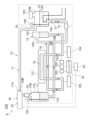
- FIG. 1 is a schematic diagram of a cooling system according to an embodiment.
- 2 is a block diagram showing a functional configuration of a controller constituting the cooling system of FIG. 1 .
- FIG. 2 is a pH diagram of an example of a refrigerant used in the cooling system of FIG. 1.
- FIG. 2 is a schematic diagram of a plasma etching apparatus including the cooling system of FIG. 1 as an application example of the cooling system.
- FIG. 2 is a schematic diagram of a cooking appliance including the cooling system, which is an application example of the cooling system of FIG. 1.
- FIG. 2 is a schematic diagram of a molding apparatus including the cooling system of FIG. 1 , showing an application example of the cooling system.
- FIG. 2 is a schematic diagram of a refrigerated warehouse equipped with the cooling system of FIG. 1 as an application example.
- FIG. 13 is a diagram illustrating a cooling system according to a modified example.
- FIG. 1 is a schematic diagram of a cooling system S according to one embodiment. First, the configuration of the cooling system S will be described.
- the cooling system S includes a refrigerant flow device 10 , a pressure reducing device 20 , and a controller 30 .
- the refrigerant flow device 10 has a refrigerant flow path 11 through which the refrigerant flows.
- the refrigerant flow path 11 includes an upstream end 11U and a downstream end 11D.
- the pressure reducing device 20 includes an inlet 20A that is connected to the downstream end 11D of the refrigerant flow path 11 and draws gas from the refrigerant flow path 11, and an outlet 20B that is connected to the upstream end 11U of the refrigerant flow path 11 and allows the gas drawn from the inlet 20A to flow from the upstream end 11U into the refrigerant flow path 11.
- the refrigerant flow device 10 has a reservoir tank 12, a dryer 13, a control valve 14, a two-phase flow separator 15, a temperature control unit 16, a gas-liquid separator 17, and a butterfly valve 18, which are arranged in this order from the upstream side to the downstream side, in the refrigerant flow path 11. That is, the refrigerant flow path 11 is constructed by connecting the reservoir tank 12, the dryer 13, the control valve 14, the two-phase flow separator 15, the temperature control unit 16, the gas-liquid separator 17, and the butterfly valve 18 in this order with piping members.
- the control valve 14 in the refrigerant flow path 11 is controlled to a narrowed opening state.
- the pressure reducing device 20 sucks in gas present in the refrigerant flow path 11 or gas vaporized within the refrigerant flow path 11 from the downstream end 11D of the refrigerant flow path 11. In this way, the pressure reducing device 20 reduces or maintains a reduced pressure inside the portion of the refrigerant flow path 11 downstream of the control valve 14.
- the pressure inside the portion of the refrigerant flow path 11 downstream of the control valve 14 is reduced to a pressure lower than atmospheric pressure.
- the pressure inside the portion of the refrigerant flow path 11 upstream of the control valve 14 is higher than the pressure inside the portion of the refrigerant flow path 11 downstream of the control valve 14, and is set to, for example, atmospheric pressure.
- the refrigerant flow device 10 flows the refrigerant contained in the gas flowing in from the pressure reducing device 20 through the refrigerant flow path 11.
- the refrigerant flow device 10 liquefies the refrigerant as much as possible before it reaches the control valve 14 in the refrigerant flow path 11.
- the liquefied refrigerant is then depressurized and cooled when it flows into the part of the refrigerant flow path 11 downstream of the control valve 14.
- the refrigerant and the temperature control target exchange heat in the temperature control unit 16, allowing the temperature control target to be cooled by the refrigerant.
- the refrigerant that exchanges heat with the temperature control object in the temperature control unit 16 can evaporate by absorbing the heat of the temperature control object.
- the refrigerant can efficiently cool the temperature control object by the latent heat of vaporization.
- the evaporated refrigerant is in a gaseous state and is sucked in by the pressure reducing device 20.
- the gaseous refrigerant sucked in by the pressure reducing device 20 absorbs heat from the temperature control object.
- the heat absorbed by the refrigerant is released to the outside, mainly in the reservoir tank 12 in the refrigerant flow path 11. This allows the temperature control object to be continuously cooled.
- the refrigerant circulated by the cooling system S is not particularly limited, but is, for example, a substance that becomes liquid under atmospheric pressure and at a standard environmental temperature (e.g., 25°C) and that becomes -5°C or lower when expanded from this state in an environment of, for example, 0.1 atmosphere, and is preferably a substance that becomes -30°C or lower when expanded in an environment of 0.01 atmosphere.
- atmospheric pressure means 1 atmosphere, or in other words, 0.1 MPa (Abs).
- the refrigerant flow device 10 and pressure reduction device 20 that make up the cooling system S are described in detail below.
- the reservoir tank 12 in the refrigerant flow device 10 stores the refrigerant that has become liquid from the gas that has flowed into the refrigerant flow path 11 from the pressure reducing device 20.
- the internal pressure of the portion of the refrigerant flow path 11 upstream of the control valve 14 is greater than the internal pressure of the portion of the refrigerant flow path 11 downstream of the control valve 14. Therefore, the gas that has flowed into the refrigerant flow path 11 from the pressure reducing device 20 becomes pressurized and its temperature increases. At this time, the refrigerant contained in the gas also becomes pressurized from its gas phase, its temperature increases, and it attempts to liquefy.
- the refrigerant contained in the gas flowing in from the pressure reducing device 20 may become at least partially liquid before it reaches the reservoir tank 12.
- the reservoir tank 12 can store the refrigerant that has naturally become liquid in this way. However, it may be difficult to liquefy all of the gas-phase refrigerant flowing in from the pressure reducing device 20 before it reaches the reservoir tank 12. Therefore, the reservoir tank 12 in this embodiment has a cooler 12A that cools and liquefies the gas-phase refrigerant.
- the cooler 12A is provided in the reservoir tank 12 and mainly cools the gas that flows into the reservoir tank 12 from the pressure reducing device 20.
- the cooler 12A may be provided outside the reservoir tank 12, and may be configured to cool, for example, the upstream portion of the reservoir tank 12 in the refrigerant flow path 11.
- the reservoir tank 12 has a gas inlet 12i at its top and an outlet 12e at its bottom for discharging liquid-phase refrigerant downstream.
- the reservoir tank 12 comprises a container body 12B with an opening and a lid 12C for opening and closing the opening, with the inlet 12i provided at the top of the container body 12B and the outlet 12e provided at the bottom of the container body 12B.
- the positions of the inlet 12i and the outlet 12e are not particularly limited.
- opening the lid 12C of the reservoir tank 12 for example, a pressure increase in the reservoir tank 12 can be avoided and power consumption of the pressure reducing device 20 can be reduced.
- opening the lid 12C it is possible to fill or replenish the refrigerant.
- the dryer 13 adsorbs moisture and foreign matter contained in the liquid refrigerant from the reservoir tank 12.
- the dryer 13 may be constructed, for example, by housing a porous material in a canister (container).
- the porous material may be a molecular sieve, activated alumina, or a mixture of these.
- the control valve 14 controls the flow of the refrigerant flowing in from the dryer 13. More specifically, the control valve 14 controls the flow of the refrigerant, mainly in liquid phase, flowing in from the dryer 13.
- the control valve 14 narrows its opening to restrict the flow of the refrigerant as soon as the suction operation of the pressure reducing device 20 begins, thereby controlling the inside of the portion of the refrigerant flow path 11 downstream of the control valve 14 to a desired reduced pressure state.
- the control valve 14 can adjust the flow rate of the refrigerant flowing out downstream from the control valve 14 to adjust, for example, the temperature or cooling capacity of the refrigerant flowing through the temperature control unit 16.
- the pressure inside the portion of the refrigerant flow path 11 upstream of the control valve 14 is greater than the pressure inside the portion of the refrigerant flow path 11 downstream of the control valve 14. Therefore, the refrigerant passing through the control valve 14 is depressurized and its temperature drops when it flows into the portion of the refrigerant flow path 11 downstream of the control valve 14. In other words, the refrigerant passing through the control valve 14 is expanded and its temperature drops when it flows into the portion of the refrigerant flow path 11 downstream of the control valve 14. Therefore, the control valve 14 also functions like an expansion valve in a refrigeration circuit, expanding liquid-phase refrigerant.
- the refrigerant flowing out of the control valve 14 may be partially vaporized by expansion. Therefore, the refrigerant flowing out of the control valve 14 may flow downstream in a gas-liquid mixed phase state. However, the refrigerant flowing out of the control valve 14 may also flow downstream in liquid phase. In either case, the refrigerant is depressurized (expanded), so its temperature decreases.
- control valve 14 is electrically connected to the controller 30. The control valve 14 is controlled by the controller 30.
- the two-phase flow separator 15 includes an inlet 15A through which the refrigerant from the control valve 14 flows in, and an outlet 15B that is located below the inlet 15A and through which the refrigerant flowing in from the inlet 15A flows out.
- the temperature of the refrigerant located in the downstream region is basically lower than the temperature of the refrigerant located in the upstream region.
- the temperature of the refrigerant immediately after it flows out of the control valve 14 is usually higher than the temperature of the refrigerant already present in the downstream region.
- the refrigerant immediately after it flows out of the control valve 14 flows so as to be drawn rapidly downstream. Therefore, the two-phase flow separator 15 is provided to prevent the high-temperature phase of the refrigerant flowing out of the control valve 14 from flowing out rapidly downstream.
- the two-phase flow separator 15 by providing the inlet 15A above the outlet 15B, it becomes difficult for the high-temperature phase of the refrigerant to flow straight toward the outlet 15B. Also, the high-temperature phase of the refrigerant tends to flow upwards relatively more than the lower-temperature phase, and therefore it becomes difficult for it to flow straight toward the outlet 15B. As described above, the two-phase flow separator 15 prevents the high-temperature phase of the refrigerant that has flowed into the two-phase flow separator 15 from flowing straight toward the outlet 15B, thereby preventing the high-temperature phase from suddenly flowing downstream.
- the two-layer flow separator 15 has a container body 15C that defines an internal space to form a flow path cross-sectional area larger than the flow path cross-sectional area of the piping member connecting the inlet 15A and the control valve 14.
- the inlet 15A is provided at the upper part of the side wall of the container body 15C (the part above the center in the vertical direction of the side wall), and the outlet 15B is provided at the bottom wall of the container body 15C.
- the inlet 15A and the outlet 15B do not overlap in the horizontal direction.
- the inlet 15A and the outlet 15B are relatively far apart in the vertical direction. In this configuration, the high-temperature phase of the refrigerant flowing out of the control valve 14 is unlikely to reach the outlet 15B.
- the positions of the inlet 15A and the outlet 15B are not particularly limited.
- the state in which the inlet 15A and the outlet 15B do not overlap in the horizontal direction means that when the inlet 15A is projected horizontally toward the outlet 15B, the two do not overlap at all.
- the positions of the inlet 15A and outlet 15B are not limited to this embodiment.
- FIG 1 the inside of the two-phase flow separator 15 is shown color-coded. This indicates that the part of the refrigerant shown in a darker color (the lower part in the figure) has a lower temperature than the part of the refrigerant shown in a lighter color (the upper part in the figure).
- the temperature control unit 16 allows the refrigerant flowing out of the two-phase flow separator 15 to flow, and uses this refrigerant to cool a temperature-controlled object (not shown).
- the temperature control unit 16 may be formed, for example, in a serpentine shape, a spiral shape, or a curved shape. There are no particular limitations on the configuration of the temperature control unit 16, and the temperature control unit 16 may be formed, for example, by a fin-tube type heat exchanger, or may include a plate-shaped heat transfer body.
- the gas-liquid separator 17 receives the refrigerant that has passed through the temperature control unit 16 and separates the refrigerant into a gas phase portion and a liquid phase portion. More specifically, the gas-liquid separator 17 separates the gas phase portion and the liquid phase portion so that the gas phase portion of the refrigerant that has passed through the temperature control unit 16 flows downstream of the liquid phase portion.
- the temperature control unit 16 exchanges heat with the refrigerant with a temperature control target, some of the refrigerant may evaporate and become gas. Therefore, the refrigerant flowing from the temperature control unit 16 to the gas-liquid separator 17 may include a gas phase portion and a liquid phase portion.
- the gas-liquid separator 17 separates the gas phase refrigerant and liquid phase refrigerant that has passed through the temperature control unit 16 and functions to flow the gas phase refrigerant upward.
- the gas-liquid separator 17 includes an inlet 17A through which the refrigerant from the temperature control unit 16 flows in, and an outlet 17B that is provided above the inlet 17A and through which the refrigerant that flows in from the inlet 17A flows out.
- the gas-liquid separator 17 has a container body 17C that defines an internal space so as to form a flow path cross-sectional area larger than the flow path cross-sectional area of the piping member that connects the inlet 17A and the temperature control unit 16.
- the inlet 17A is provided on the bottom wall of the container body 17C
- the outlet 17B is provided on the top wall of the container body 17C.
- the positions of the inlet 17A and the outlet 17B are not particularly limited, but it is preferable that the inlet 17A and the outlet 17B are largely separated in the vertical direction. In this case, since the gas phase tends to flow upward more than the liquid phase, the gas phase portion of the refrigerant that flows downstream in the gas-liquid separator 17 is easily discharged downstream from the outlet 17B. In addition, the situation in which the liquid phase refrigerant is sucked into the pressure reducing device 20 is suppressed.
- the dark colored parts inside the gas-liquid separator 17 indicate the liquid phase parts, and the parts above them indicate the gas phase parts. It is preferable to introduce the liquid phase refrigerant into the gas-liquid separator 17 so that the gas phase is always formed at the top.
- the environment in which the liquid phase refrigerant and the gas phase parts coexist in the gas-liquid separator 17 can be created by controlling the operation of the pressure reducing device 20, the control valve 14, etc.
- the gas-liquid separator 17 is configured to have a structure that can maintain its shape when the internal pressure is reduced, and may be configured as a so-called vacuum insulated container.
- the maintenance of the shape of the gas-liquid separator 17 during reduction depends on the internal pressure to be reduced, but when the pressure is reduced to, for example, 0.1 atmosphere, it is preferable that the outer shell part of the gas-liquid separator 17 is formed from a thick hard metal or the like.
- the specific structure of the gas-liquid separator 17 may be appropriately determined according to the expected degree of reduction in pressure, and is not particularly limited.
- the gas-liquid separator 17 and the reservoir tank 12 are arranged at the same or approximately the same position in the vertical direction.
- the refrigerant flows so that the liquid level of the liquid phase refrigerant in the gas-liquid separator 17 and the liquid level of the liquid phase refrigerant in the reservoir tank 12 are the same.
- the butterfly valve 18 is a valve that controls the amount of gas sucked into the refrigerant flow path 11 by the pressure reducing device 20.
- the butterfly valve 18 may be configured to control the opening degree by, for example, an electric motor.
- the butterfly valve 18 is electrically connected to the controller 30.
- the butterfly valve 18 is controlled by the controller 30.
- the portion of the refrigerant flow path 11 between the control valve 14 and the temperature control unit 16 and the portion of the refrigerant flow path 11 downstream of the temperature control unit 16 constitute an internal heat exchanger 19 that allows the refrigerants flowing therethrough to exchange heat with each other.
- the portion of the refrigerant flow path 11 between the control valve 14 and the temperature control unit 16 is, in detail, the portion downstream of the control valve 14 and upstream of the two-phase flow separator 15 in the refrigerant flow path 11, and is upstream of the temperature control unit 16.
- the portion downstream of the temperature control unit 16 in the refrigerant flow path 11 is, in detail, the portion between the temperature control unit 16 and the gas-liquid separator 17 in the refrigerant flow path 11.
- the refrigerant flowing through the portion of the refrigerant flow path 11 between the control valve 14 and the temperature control unit 16 can be cooled.
- the refrigerant flowing through the portion of the refrigerant flow path 11 between the temperature control unit 16 and the gas-liquid separator 17 can be heated.
- the refrigerant flow device 10 also includes a first temperature sensor 101, a second temperature sensor 102, a third temperature sensor 103, a first pressure sensor 104, a second pressure sensor 105, a first liquid level sensor 106, and a second liquid level sensor 107.
- the first temperature sensor 101 detects the temperature of the refrigerant flowing through the temperature control unit 16.
- the second temperature sensor 102 detects the temperature of the refrigerant flowing through the portion of the refrigerant flow path 11 between the two-phase flow separator 15 and the temperature control unit 16.
- the third temperature sensor 103 detects the temperature of the refrigerant flowing through the portion of the refrigerant flow path 11 between the temperature control unit 16 and the gas-liquid separator 17 (the portion upstream of the internal heat exchanger 19).
- the first pressure sensor 104 detects the pressure of the refrigerant flowing through the portion of the refrigerant flow path 11 between the two-phase flow separator 15 and the temperature control unit 16.
- the second pressure sensor 105 detects the pressure of the refrigerant flowing through the portion of the refrigerant flow path 11 between the temperature control unit 16 and the gas-liquid separator 17 (the portion upstream of the internal heat exchanger 19).
- the first liquid level sensor 106 detects the level of the liquid-phase refrigerant stored in the reservoir tank 12.
- the second liquid level sensor 107 detects the level of the liquid-phase refrigerant stored in the gas-liquid separator 17.
- the first liquid level sensor 106 and the second liquid level sensor 107 may be configured as an optical sensor, for example a laser displacement meter, in which case light is irradiated onto the liquid surface from above and the reflected light is received to calculate the liquid level.
- the first liquid level sensor 106 and the second liquid level sensor 107 may also be configured as a float-type sensor.
- Each sensor (101-107) is electrically connected to the controller 30, and the detection results of each sensor are sent to the controller 30.
- the pressure reducing device 20 has a gas suction pump 22 that sucks gas from the refrigerant flow path 11.
- the gas suction pump 22 sucks gas from the refrigerant flow path 11 through an inlet 20A connected to the downstream end 11D of the refrigerant flow path 11, and causes the gas sucked from the inlet 20A to flow into the refrigerant flow path 11 through an outlet 20B connected to the upstream end 11U of the refrigerant flow path 11.
- the inlet 20A and the outlet 20B may be formed in the gas suction pump 22, or may be formed in a piping portion connected to the gas suction pump 22.
- the type of the gas suction pump 22 is not particularly limited, but it is preferable that it is a dry vacuum pump in which lubricating oil does not flow out or hardly flows out into the suction path side.
- the dry vacuum pump may be a diaphragm type dry vacuum pump, a rocking piston type dry vacuum pump, a rotary vane type dry vacuum pump, a scroll type dry vacuum pump, etc., and may be a type different from the above examples.
- the gas suction pump 22 may also be a wet vacuum pump.
- the gas suction pump 22 is a dry vacuum pump.
- the gas suction pump 22 includes a motor controlled by an inverter, such as an AC motor or a brushless DC motor.
- the gas suction pump 22 adjusts the amount of gas suctioned by adjusting the rotation speed of the motor, and is therefore capable of adjusting the internal pressure of the portion of the refrigerant flow path 11 downstream of the control valve 14.
- the gas suction pump 22 is electrically connected to the controller 30 and is controlled by the controller 30.
- the gas suction pump 22 is electrically connected to the controller 30 via the inverter 40.
- the rotation speed of the motor is adjusted by the controller 30 adjusting the frequency of the alternating current supplied to the motor using the inverter 40.
- the controller 30 is electrically connected to each of the above-mentioned sensors (101 to 107), and is also electrically connected to the control valve 14, the butterfly valve 18, and the gas suction pump 22.
- the controller 30 may be configured, for example, as a computer having a CPU, ROM, etc. In this case, the controller 30 performs various processes according to the programs stored in the ROM. Note that the controller 30 may also be configured with other processors and electrical circuits (for example, an FPGA (Field Programmable Gate Alley), etc.).
- Fig. 2 is a block diagram showing the functional configuration of the controller 30.
- the controller 30 has a sensor information acquisition unit 31, a rotation speed adjustment unit 32, and a valve opening adjustment unit 33.
- the controller 30 may be configured, for example, by one computer or by multiple computers. When configured by multiple computers, the multiple functional units may be distributed among the multiple computers.
- the sensor information acquisition unit 31 is a part that acquires the detection results from the first temperature sensor 101, the second temperature sensor 102, the third temperature sensor 103, the first pressure sensor 104, the second pressure sensor 105, the first liquid level sensor 106, and the second liquid level sensor 107 described above.
- the sensor information acquisition unit 31 provides one or more pieces of information relating to the acquired detection results to the rotation speed adjustment unit 32 and the valve opening adjustment unit 33.
- the rotation speed adjustment unit 32 is electrically connected to the gas suction pump 22 and controls the operation of the gas suction pump 22. More specifically, the rotation speed adjustment unit 32 is connected to the motor in the gas suction pump 22 via an inverter 40. The rotation speed adjustment unit 32 adjusts the frequency of the alternating current supplied from the inverter 40 to the motor, thereby adjusting the flow rate of gas sucked by the pressure reducing device 20 from the refrigerant flow path 11.
- the target temperature of the refrigerant in the temperature control unit 16 or before it flows into the temperature control unit 16 is input and held in the rotation speed adjustment unit 32, for example, by an input device not shown, and the rotation speed adjustment unit 32 adjusts the rotation speed of the motor of the gas suction pump 22 so that the temperature detected by the first temperature sensor 101 or the second temperature sensor 102 matches the target temperature.
- the gas suction pump 22 may be controlled according to the difference between the temperature of the refrigerant detected by the first temperature sensor 101 or the second temperature sensor 102 and the target temperature.
- the gas suction pump 22 of the pressure reducing device 20 is controlled so that the temperature of the refrigerant matches the target temperature, but instead, the motor rotation speed may be adjusted so that the pressure of the refrigerant in the refrigerant flow path 11 matches the target value.
- the valve opening adjustment unit 33 is electrically connected to the control valve 14 and the butterfly valve 18, and controls the operation of the control valve 14 and the butterfly valve 18.
- the valve opening adjustment unit 33 adjusts the opening of the control valve 14 to adjust the flow rate of the refrigerant flowing through the refrigerant flow path 11.
- the valve opening adjustment unit 33 also adjusts the opening of the butterfly valve 18 to adjust the amount of gas sucked in by the pressure reducing device 20.
- the target temperature of the refrigerant at the temperature control unit 16 or before it flows into the temperature control unit 16 is input and held in the valve opening adjustment unit 33, for example, by an input device not shown, and the opening of the control valve 14 or the opening of the butterfly valve 18 is adjusted so that the temperature detected by the first temperature sensor 101 or the second temperature sensor 102 matches the target temperature.
- Such control of the opening of the control valve 14 or the butterfly valve 18 may be performed after the gas suction pump 22 is controlled so that the temperature of the refrigerant matches the target temperature and the operating state of the gas suction pump 22 is maintained constant.
- the refrigerant is a substance that becomes liquid under atmospheric pressure and at a standard environmental temperature (for example, 25°C), and when expanded from this state in an environment of, for example, 0.1 atmospheric pressure, the temperature becomes -5°C or lower, and preferably becomes -30°C or lower when expanded in an environment of 0.01 atmospheric pressure.
- the refrigerant is preferably a low-environmental-load refrigerant with a global warming potential (GWP) of 10 or lower.
- GWP global warming potential
- the substance becomes liquid under atmospheric pressure and at a standard environmental temperature (for example, 25°C).
- the boiling point of the refrigerant used under atmospheric pressure may be 50°C or higher, 60°C or higher, or 70°C or higher.
- HFO-1336mzz-Z which has a GWP of 2 and is non-flammable, can be suitably used as the refrigerant.
- the refrigerant may be Opteon SF33 (TM) manufactured by Mitsui-Chemours Fluoroproducts, Inc.
- Figure 3 is a pH diagram of HFO-1336mzz-Z.
- HFO-1336mzz-Z When HFO-1336mzz-Z is depressurized from a state (St1) of approximately 33°C, close to room temperature, at approximately 0.100 MPa, close to atmospheric pressure, to 0.0149 MPa, the temperature drops to approximately -10°C (St2).
- St2 a state of approximately 33°C, close to room temperature, at approximately 0.100 MPa, close to atmospheric pressure, to 0.0149 MPa
- the temperature drops to approximately -10°C (St2).
- St2 When it is depressurized to 0.001 MPa, the temperature drops to approximately -50°C or lower. Then, when it absorbs a certain amount of heat from the state St2 where it has been cooled to approximately -10°C, it evaporates (St3).
- Such HFO-1336mzz-Z can be cooled, for example, by cooler 12A in reservoir tank 12, transitioning to state St1 above, and then be depressurized by flowing out of control valve 14, transitioning to state St2, for example.
- HFO-1336mzz-Z can then transition from state St2 to state St3 by exchanging heat with a temperature-controlled object in temperature control unit 16, and then transition from state St3 to state St4 by flowing out of gas-liquid separator 17 to the outside of pressure-reducing device 20. Therefore, HFO-1336mzz-Z can be suitably used in cooling system S.
- refrigerants that can be used in the cooling system S, such as water and ethanol.
- a desired flow rate of refrigerant is stored in the refrigerant flow path 11 from the reservoir tank 12 to the gas-liquid separator 17. Then, for example, a target temperature of the refrigerant flowing through the temperature control unit 16 is input and maintained. Then, the pressure reducing device 20 is driven, and the pressure inside the portion of the refrigerant flow path 11 downstream of the control valve 14 is reduced by the pressure reducing device 20 to a pressure lower than atmospheric pressure. At this time, the control valve 14 may be closed or may be narrowed to a small opening. Then, the pressure reducing device 20 adjusts the rotation speed of the motor of the gas suction pump 22 until the temperature detected by the first temperature sensor 101 matches the target temperature.
- the pressure inside the portion downstream of the control valve 14 in the refrigerant flow path 11 is reduced to a pressure lower than atmospheric pressure by the pressure reducing device 20, and the pressure inside the portion upstream of the control valve 14 in the refrigerant flow path 11 is set to a pressure higher than the pressure inside the downstream portion, for example, atmospheric pressure.
- the pressure inside the portion upstream of the control valve 14 in the refrigerant flow path 11 does not have to be strictly atmospheric pressure, and may be a pressure slightly lower than atmospheric pressure.
- the temperature control unit 16 transitions to a state in which the temperature-controlled object is cooled.
- the gas phase portion is sucked by the pressure reducing device 20 and flows back into the refrigerant flow path 11 from the upstream end 11U of the refrigerant flow path 11, where it is cooled on its way to the control valve 14, and then flows back into the temperature control unit 16 through the control valve 14. In this way, the temperature-controlled object is continuously cooled by the refrigerant.
- the refrigerant that absorbs the heat of the temperature control object in the temperature control unit 16 flows from the downstream end 11D of the refrigerant flow path 11 through the pressure reducing device 20 to the upstream end 11U of the refrigerant flow path 11, and is cooled by the cooler 12A or the like before reaching the control valve 14, and transitions from state St4 to state St1 in FIG. 3.
- the refrigerant then flows out of the control valve 14, and is depressurized in the portion of the refrigerant flow path 11 downstream of the control valve 14, transitioning to state St2.
- the refrigerant then transitions from state St2 to state St3 by exchanging heat with the temperature control object in the temperature control unit 16.
- the refrigerant then transitions from state St3 to state St4 by flowing from the pressure reducing device 20 into the portion of the refrigerant flow path 11 upstream of the control valve 14.
- the refrigerant is then cooled before reaching the control valve 14, and transitions from state St4 to state St1.
- the temperature control object is continuously cooled by the refrigerant.
- the cooling system S includes a refrigerant flow device 10 including a refrigerant flow path 11 through which a refrigerant flows, a control valve 14 provided in the refrigerant flow path 11 and controlling the flow of the refrigerant, and a pressure reducing device 20 including an inlet 20A connected to the downstream end 11D of the refrigerant flow path 11 to draw gas from the refrigerant flow path 11, and an outlet 20B connected to the upstream end 11U of the refrigerant flow path 11 to allow the gas drawn from the inlet 20A to flow from the upstream end 11U of the refrigerant flow path 11 into the refrigerant flow path 11.
- a refrigerant flow device 10 including a refrigerant flow path 11 through which a refrigerant flows, a control valve 14 provided in the refrigerant flow path 11 and controlling the flow of the refrigerant, and a pressure reducing device 20 including an inlet 20A connected to the downstream end 11D of the refrigerant flow path 11 to draw gas from the
- the refrigerant flow path 11 allows the refrigerant contained in the gas flowing in from the pressure reducing device 20 to flow.
- the refrigerant flow device 10 includes a temperature control unit 16 downstream of the control valve 14 in the refrigerant flow path 11 to cool a temperature control target with the refrigerant.
- a substance that becomes liquid under atmospheric pressure and at a standard environmental temperature (e.g., 25°C) and becomes -5°C or lower when expanded from this state in an environment of, for example, 0.1 atmospheric pressure can be used as the refrigerant.
- a standard environmental temperature e.g. 25°C
- the compressor will compress the liquid, so the compressor will not function properly and the substance will not evaporate in the evaporator. Therefore, the above refrigerant is not suitable for a vapor compression refrigeration cycle.
- the cooling system S does not use compression, but reduces the pressure of the above refrigerant in the portion downstream of the control valve 14 in the refrigerant flow path 11, making it possible to cool the temperature control target, and the heat of the temperature control target can be released from the portion upstream of the control valve 14 in the refrigerant flow path 11, thereby realizing a heat cycle. Therefore, according to this embodiment, it becomes possible to use a substance that has not been used in conventional refrigeration methods as a refrigerant for a heat cycle, or to expand the range of substances that can be used as refrigerants for a heat cycle.
- the cooling system S is capable of using, for example, HFO-1336mzz-Z, which has a GWP of 2 and is non-flammable, as a refrigerant. This makes it possible to achieve a cooling operation with a low GWP and ensured safety, which is currently not possible with vapor compression refrigeration cycles. No other cooling system S is known that has such a low GWP, low environmental impact, and ensures safety. Therefore, the realization of such a cooling system S has the potential to greatly contribute to protecting the global environment. In addition, because the cooling system S does not use a compressor, the situation in which lubricating oil leaks into the refrigerant is suppressed, which is also beneficial in this respect.
- the cooling system S also includes a gas-liquid separator 17 downstream of the temperature control unit 16 in the refrigerant flow path 11, which separates the gas phase and liquid phase portions of the refrigerant that has passed through the temperature control unit 16 so that the gas phase portion flows downstream of the liquid phase portion.
- This configuration prevents liquid phase refrigerant from being sucked into the pressure reducing device 20 from the downstream end 11D of the refrigerant flow path 11. This allows the pressure reducing device 20 to operate in a stable state, improving the operational stability of the cooling system S.
- the refrigerant flow device 10 also includes a reservoir tank 12 upstream of the control valve 14 in the refrigerant flow path 11, which stores the refrigerant that has become liquid from the gas state that has flowed into the refrigerant flow path 11 from the pressure reducing device 20.
- the control valve 14 controls the flow of the liquid-phase refrigerant that flows in from the reservoir tank 12. In this configuration, the refrigerant that has flowed into the refrigerant flow path 11 from the pressure reducing device 20 and is in the gas phase, which has a relatively high temperature, is prevented from flowing downstream of the control valve 14 in the refrigerant flow path 11. This allows the temperature control unit 16 to perform the desired cooling.
- the refrigerant flow device 10 also includes a two-phase flow separator 15 between the control valve 14 and the temperature control unit 16 in the refrigerant flow path 11.
- the two-phase flow separator 15 includes an inlet 15A through which the refrigerant from the control valve 14 flows in, and an outlet 15B that is located below the inlet 15A and through which the refrigerant that flows in from the inlet 15A flows out.
- the portion of the refrigerant flow path 11 between the control valve 14 and the temperature control unit 16 and the portion of the refrigerant flow path 11 downstream of the temperature control unit 16 constitute an internal heat exchanger 19 that allows the refrigerants flowing through each of them to exchange heat with each other.
- the refrigerant flowing through the portion of the refrigerant flow path 11 between the control valve 14 and the temperature control unit 16 can be cooled.
- the refrigerant flowing through the portion of the refrigerant flow path 11 between the temperature control unit 16 and the gas-liquid separator 17 can be heated. This further reduces the temperature of the refrigerant flowing into the temperature control unit 16, and makes it easier for the refrigerant flowing into the gas-liquid separator 17 to vaporize. Therefore, the cooling system S can be operated in a desired state.
- FIG. 4 is a schematic diagram of a plasma etching apparatus 200 including a cooling system S.
- the plasma etching apparatus 200 includes an electrostatic chuck 201.
- the electrostatic chuck 201 includes a plate-shaped base plate 202, and adsorbs and holds a wafer W on the surface of the base plate 202.
- the base plate 202 and the temperature control unit 16 of the cooling system S are connected so that the temperature control unit 16 passes through the inside of the base plate 202.
- the temperature control unit 16 can cool the base plate 202 and the wafer W by absorbing heat from the base plate 202.
- the first temperature sensor 101 of the cooling system S is configured to detect the temperature of the base plate 202.
- the base plate 202 also includes a built-in heater 203.
- the wafer W can be cooled and heated.
- the cooling system S in FIG. 4 includes a fan 120 for cooling the upstream portion of the reservoir tank 12 in the coolant flow passage 11. This promotes liquefaction of the refrigerant that has flowed from the pressure reducing device 20 into the refrigerant flow passage 11.
- a fan 120 can also be applied to the cooling system S in the above-described embodiment and the following application example.
- (Application Example 2) 5 is a schematic diagram of a cooking appliance 210 equipped with a cooling system S.
- the cooking appliance 210 is a so-called cold plate, and is equipped with a cooking plate 211 cooled by a temperature control unit 16 of the cooling system S.
- the temperature control unit 16 is connected to the cooking plate 211 in a state where it passes through the inside of the cooking plate 211.
- the first temperature sensor 101 of the cooling system S is configured to detect the temperature of the cooking plate 211.
- (Application Example 3) 6 is a schematic diagram of a molding apparatus 220 equipped with a cooling system S.
- the molding apparatus 220 is equipped with a mold 221 cooled by a temperature control unit 16 of the cooling system S.
- the temperature control unit 16 is connected to the mold 221 in a state where it passes through the inside of the mold 221.
- a first temperature sensor 101 of the cooling system S is configured to detect the temperature of the mold 221.
- FIG. 7 is a schematic diagram of a refrigerated warehouse 230 equipped with a cooling system S.
- the refrigerated warehouse 230 includes a warehouse body 231 and a duct 232 connected to the warehouse body 231.
- the duct 232 is connected to the warehouse body 231 at both ends, draws in gas from the warehouse body 231 at one end, and allows the drawn gas to flow into the warehouse body 231 from the other end.
- a fan 233 is disposed in the duct 232, and a temperature control unit 16 of the cooling system S is also disposed in the duct 232. By rotating the fan 233, gas is drawn in from the warehouse body 231, and the gas is cooled by the temperature control unit 16. As a result, the cooled gas flows into the warehouse body 231 from the duct 232.
- the first temperature sensor 101 for detecting the temperature of the temperature control unit 16 is not provided, but the first temperature sensor 101 may be provided.
- cooling system S can be used for various purposes other than the application examples exemplified above.
- cooling system Sv a cooling system Sv according to a modified example will be described with reference to FIG. 8.
- the temperature control unit 16 and the gas-liquid separator 17 are integrated, and the temperature control unit 16 is not provided between the control valve 14 and the two-phase flow separator 15 as in the above-described embodiment.
- the gas-liquid separator 17 is configured to cool a temperature-controlled object with a liquid-phase refrigerant therein.
- the temperature-controlled object is a heat medium flowing through a heat medium piping member 240.
- the heat medium piping member 240 is connected to the gas-liquid separator 17 so as to pass through the inside of the gas-liquid separator 17.
- the cooling system Sv also includes a dryer 13, a control valve 14, a two-phase flow separator 15, a temperature control unit 16, a gas-liquid separator 17, a butterfly valve 18, and an internal heat exchanger 19, which are similar to those in the above-described embodiment. Each of these components is similar to those in the above-described embodiment.
- the temperature control target is cooled with a liquid-phase refrigerant inside the gas-liquid separator 17, but cooling may also be performed with a gas-phase refrigerant.
- the cooling system Sv may also be configured to perform cooling on the outer surface of the gas-liquid separator 17.
Landscapes
- Engineering & Computer Science (AREA)
- Physics & Mathematics (AREA)
- Thermal Sciences (AREA)
- Mechanical Engineering (AREA)
- General Engineering & Computer Science (AREA)
- Chemical & Material Sciences (AREA)
- Chemical Kinetics & Catalysis (AREA)
- Combustion & Propulsion (AREA)
- Materials Engineering (AREA)
- Organic Chemistry (AREA)
- Analytical Chemistry (AREA)
- Power Engineering (AREA)
- Life Sciences & Earth Sciences (AREA)
- Sustainable Development (AREA)
- Cooling Or The Like Of Semiconductors Or Solid State Devices (AREA)
Priority Applications (3)
| Application Number | Priority Date | Filing Date | Title |
|---|---|---|---|
| EP24792597.7A EP4700316A1 (en) | 2023-04-18 | 2024-04-12 | Cooling system |
| KR1020257031131A KR20250169159A (ko) | 2023-04-18 | 2024-04-12 | 냉각 시스템 |
| CN202480021290.XA CN120936845A (zh) | 2023-04-18 | 2024-04-12 | 冷却系统 |
Applications Claiming Priority (2)
| Application Number | Priority Date | Filing Date | Title |
|---|---|---|---|
| JP2023068041A JP2024154289A (ja) | 2023-04-18 | 2023-04-18 | 冷却システム |
| JP2023-068041 | 2023-04-18 |
Publications (1)
| Publication Number | Publication Date |
|---|---|
| WO2024219322A1 true WO2024219322A1 (ja) | 2024-10-24 |
Family
ID=93152431
Family Applications (1)
| Application Number | Title | Priority Date | Filing Date |
|---|---|---|---|
| PCT/JP2024/014760 Ceased WO2024219322A1 (ja) | 2023-04-18 | 2024-04-12 | 冷却システム |
Country Status (6)
| Country | Link |
|---|---|
| EP (1) | EP4700316A1 (https=) |
| JP (1) | JP2024154289A (https=) |
| KR (1) | KR20250169159A (https=) |
| CN (1) | CN120936845A (https=) |
| TW (1) | TW202500938A (https=) |
| WO (1) | WO2024219322A1 (https=) |
Citations (9)
| Publication number | Priority date | Publication date | Assignee | Title |
|---|---|---|---|---|
| JPH0933118A (ja) * | 1994-10-14 | 1997-02-07 | Denso Corp | 空気調和装置 |
| JPH10220927A (ja) * | 1997-02-10 | 1998-08-21 | Takenaka Komuten Co Ltd | 冷凍サイクルにおける受液部の構造 |
| JP2011142298A (ja) | 2009-12-11 | 2011-07-21 | Panasonic Corp | 沸騰冷却装置 |
| JP2015105351A (ja) * | 2013-11-29 | 2015-06-08 | セントラル硝子株式会社 | 熱エネルギーを機械エネルギーへ変換する方法、有機ランキンサイクル装置、及び作動流体を置換える方法 |
| WO2017119113A1 (ja) | 2016-01-08 | 2017-07-13 | 三菱電機株式会社 | 沸騰冷却装置および沸騰冷却システム |
| WO2020246306A1 (ja) * | 2019-06-07 | 2020-12-10 | サンデン・オートモーティブクライメイトシステム株式会社 | 車両用空気調和装置 |
| JP2021050651A (ja) * | 2019-09-25 | 2021-04-01 | ダイキン工業株式会社 | ターボ圧縮機 |
| JP2021162195A (ja) | 2020-03-31 | 2021-10-11 | 宇部マテリアルズ株式会社 | 沸騰冷却用作動液、それを用いた沸騰冷却装置および沸騰冷却方法 |
| JP2022169093A (ja) * | 2021-04-27 | 2022-11-09 | 日本電気株式会社 | 冷媒回路及び冷却方法 |
-
2023
- 2023-04-18 JP JP2023068041A patent/JP2024154289A/ja active Pending
-
2024
- 2024-04-12 EP EP24792597.7A patent/EP4700316A1/en active Pending
- 2024-04-12 WO PCT/JP2024/014760 patent/WO2024219322A1/ja not_active Ceased
- 2024-04-12 KR KR1020257031131A patent/KR20250169159A/ko active Pending
- 2024-04-12 CN CN202480021290.XA patent/CN120936845A/zh active Pending
- 2024-04-16 TW TW113114142A patent/TW202500938A/zh unknown
Patent Citations (9)
| Publication number | Priority date | Publication date | Assignee | Title |
|---|---|---|---|---|
| JPH0933118A (ja) * | 1994-10-14 | 1997-02-07 | Denso Corp | 空気調和装置 |
| JPH10220927A (ja) * | 1997-02-10 | 1998-08-21 | Takenaka Komuten Co Ltd | 冷凍サイクルにおける受液部の構造 |
| JP2011142298A (ja) | 2009-12-11 | 2011-07-21 | Panasonic Corp | 沸騰冷却装置 |
| JP2015105351A (ja) * | 2013-11-29 | 2015-06-08 | セントラル硝子株式会社 | 熱エネルギーを機械エネルギーへ変換する方法、有機ランキンサイクル装置、及び作動流体を置換える方法 |
| WO2017119113A1 (ja) | 2016-01-08 | 2017-07-13 | 三菱電機株式会社 | 沸騰冷却装置および沸騰冷却システム |
| WO2020246306A1 (ja) * | 2019-06-07 | 2020-12-10 | サンデン・オートモーティブクライメイトシステム株式会社 | 車両用空気調和装置 |
| JP2021050651A (ja) * | 2019-09-25 | 2021-04-01 | ダイキン工業株式会社 | ターボ圧縮機 |
| JP2021162195A (ja) | 2020-03-31 | 2021-10-11 | 宇部マテリアルズ株式会社 | 沸騰冷却用作動液、それを用いた沸騰冷却装置および沸騰冷却方法 |
| JP2022169093A (ja) * | 2021-04-27 | 2022-11-09 | 日本電気株式会社 | 冷媒回路及び冷却方法 |
Non-Patent Citations (1)
| Title |
|---|
| See also references of EP4700316A1 |
Also Published As
| Publication number | Publication date |
|---|---|
| TW202500938A (zh) | 2025-01-01 |
| KR20250169159A (ko) | 2025-12-02 |
| CN120936845A (zh) | 2025-11-11 |
| EP4700316A1 (en) | 2026-02-25 |
| JP2024154289A (ja) | 2024-10-30 |
Similar Documents
| Publication | Publication Date | Title |
|---|---|---|
| US20230106287A1 (en) | Heat transfer circuit with increased bearing lubricant temperature, and method of supplying thereof | |
| JP6405675B2 (ja) | 冷却装置 | |
| CN103429971B (zh) | 冷冻循环装置 | |
| JP5283589B2 (ja) | 冷凍空調装置 | |
| JP2003322421A (ja) | 超臨界蒸気圧縮回路における高圧側圧力制御方法と回路装置 | |
| JPWO2014049673A1 (ja) | 空調給湯複合システム | |
| JP6486847B2 (ja) | 環境試験装置 | |
| JP5717903B2 (ja) | 冷凍空調装置 | |
| WO2024219322A1 (ja) | 冷却システム | |
| JP5836844B2 (ja) | 冷凍装置 | |
| JP5579235B2 (ja) | 冷凍空調装置 | |
| JP2004309027A (ja) | ヒートポンプ装置の制御方法 | |
| CN113432325B (zh) | 复叠式压缩制冷系统以及具有其的制冷设备 | |
| JP6536061B2 (ja) | 冷却装置 | |
| JP2006336943A (ja) | 冷凍システムおよび保冷庫 | |
| WO2018155028A1 (ja) | 直接接触熱交換器を備えた冷媒システムおよび冷媒システムの制御方法 | |
| JP2012233617A (ja) | 空気調和装置 | |
| WO2024085167A1 (ja) | 冷却システム | |
| JP7526926B2 (ja) | 冷凍装置 | |
| CN113432324B (zh) | 复叠式压缩制冷系统以及具有其的制冷设备 | |
| JP2018059655A (ja) | 冷凍サイクル装置 | |
| WO2019224870A1 (ja) | ショーケース | |
| JP2012122637A (ja) | 冷凍サイクル装置 | |
| JP2004177084A (ja) | 可燃性ガスを用いた冷凍装置、および可燃性ガスを用いた冷凍装置を有する自動販売機、および可燃性ガスを用いた冷凍装置を有する冷蔵庫 | |
| JP2018066505A (ja) | 冷凍サイクル装置 |
Legal Events
| Date | Code | Title | Description |
|---|---|---|---|
| 121 | Ep: the epo has been informed by wipo that ep was designated in this application |
Ref document number: 24792597 Country of ref document: EP Kind code of ref document: A1 |
|
| ENP | Entry into the national phase |
Ref document number: 1020257031131 Country of ref document: KR Free format text: ST27 STATUS EVENT CODE: A-0-1-A10-A15-NAP-PA0105 (AS PROVIDED BY THE NATIONAL OFFICE) |
|
| WWE | Wipo information: entry into national phase |
Ref document number: 2024792597 Country of ref document: EP |
|
| NENP | Non-entry into the national phase |
Ref country code: DE |
|
| ENP | Entry into the national phase |
Ref document number: 2024792597 Country of ref document: EP Effective date: 20251118 |
|
| WWE | Wipo information: entry into national phase |
Ref document number: 11202506777U Country of ref document: SG |
|
| WWP | Wipo information: published in national office |
Ref document number: 11202506777U Country of ref document: SG |
|
| ENP | Entry into the national phase |
Ref document number: 2024792597 Country of ref document: EP Effective date: 20251118 |
|
| ENP | Entry into the national phase |
Ref document number: 2024792597 Country of ref document: EP Effective date: 20251118 |
|
| ENP | Entry into the national phase |
Ref document number: 2024792597 Country of ref document: EP Effective date: 20251118 |
|
| ENP | Entry into the national phase |
Ref document number: 2024792597 Country of ref document: EP Effective date: 20251118 |
|
| ENP | Entry into the national phase |
Ref document number: 2024792597 Country of ref document: EP Effective date: 20251118 |
|
| ENP | Entry into the national phase |
Ref document number: 2024792597 Country of ref document: EP Effective date: 20251118 |
|
| ENP | Entry into the national phase |
Ref document number: 2024792597 Country of ref document: EP Effective date: 20251118 |
|
| ENP | Entry into the national phase |
Ref document number: 2024792597 Country of ref document: EP Effective date: 20251118 |
|
| WWP | Wipo information: published in national office |
Ref document number: 2024792597 Country of ref document: EP |