WO2024218935A1 - 組合せ計量装置の防水構造 - Google Patents
組合せ計量装置の防水構造 Download PDFInfo
- Publication number
- WO2024218935A1 WO2024218935A1 PCT/JP2023/015757 JP2023015757W WO2024218935A1 WO 2024218935 A1 WO2024218935 A1 WO 2024218935A1 JP 2023015757 W JP2023015757 W JP 2023015757W WO 2024218935 A1 WO2024218935 A1 WO 2024218935A1
- Authority
- WO
- WIPO (PCT)
- Prior art keywords
- opening
- center base
- flange portion
- case
- packing
- Prior art date
- Legal status (The legal status is an assumption and is not a legal conclusion. Google has not performed a legal analysis and makes no representation as to the accuracy of the status listed.)
- Ceased
Links
Images







Classifications
-
- G—PHYSICS
- G01—MEASURING; TESTING
- G01G—WEIGHING
- G01G19/00—Weighing apparatus or methods adapted for special purposes not provided for in the preceding groups
- G01G19/387—Weighing apparatus or methods adapted for special purposes not provided for in the preceding groups for combinatorial weighing, i.e. selecting a combination of articles whose total weight or number is closest to a desired value
- G01G19/393—Weighing apparatus or methods adapted for special purposes not provided for in the preceding groups for combinatorial weighing, i.e. selecting a combination of articles whose total weight or number is closest to a desired value using two or more weighing units
Definitions
- the present invention relates to a combination weighing device that weighs and dispenses a specified amount of various foods and other items, and more specifically, to its waterproof structure.
- a combination weighing device is provided with a dispersion feeder that radially disperses and transports items supplied from above on the top of a center base in the center of the device, and multiple linear feeders that further transport the items dispersed and transported by the dispersion feeder outward.
- multiple supply hoppers that hold and discharge the items transported by each linear feeder, and multiple weighing hoppers for weighing the items from each supply hopper are detachably attached to the outer periphery of the center base.
- a combination calculation is performed based on the weight of the items weighed in the weighing hoppers, and a combination of weighing hoppers that falls within a specified weight range is selected.
- the gate of the selected weighing hopper is opened to discharge the items, and the discharged items are collected and guided via a collecting chute or the like and fed into a packaging device or the like below.
- the base that supports the center base is equipped with an opening for maintenance that is closed by a cover plate. This opening is waterproofed to prevent cleaning water from entering the inside of the base during cleaning, thereby protecting the electrical system inside the base.
- combination weighing devices that weigh and process food products are required to be waterproof when washed, as well as have the ability to prevent the growth of bacteria.
- the present invention was made with this in mind, and aims to provide a waterproof structure for a combination weighing device that exhibits high waterproof performance and is also effective in preventing the proliferation of bacteria.
- the present invention is configured as follows.
- the waterproof structure of the combination weighing device is a waterproof structure of a combination weighing device in which a plurality of drive units, to which a plurality of hoppers are respectively attached, are respectively assembled to a plurality of openings of a center base, the housing of the drive unit is assembled so as to cover the openings of the center base, the plurality of drive units drive to open and close gates equipped at the lower parts of the plurality of hoppers, the housing comprises a metallic unit case having an opening corresponding to the opening of the center base, and a metallic cover case having an opening and covering the unit case, the outer periphery of the opening of the unit case is provided with a flange portion that abuts against the outer periphery of the center base, the outer periphery of the opening of the cover case is provided with a flange portion that covers the flange portion of the unit case from the outer periphery with a gap, the flange portion is provided in an annular shape along the circumferential direction of the opening
- the waterproof structure of the combination weighing device according to the present invention uses a packing interposed between the flange of the unit case and the flange of the cover case to seal the gap formed between the unit case and the cover case that covers it, preventing the infiltration of cleaning water into the gap and preventing the proliferation of bacteria in the gap.
- the high-pressure cleaning water that is blown into the inside of the flange from the gap between the outer circumferential surface of the center base and the leading edge of the flange of the cover case is blocked by the shielding protrusions. This prevents the high-pressure cleaning water from directly hitting the packing interposed between the flange of the unit case and the flange of the cover case, so the packing made of rubber or the like is not damaged by the high-pressure cleaning water.
- cleaning water that seeps into the cover case through the gap between the flange portion of the cover case and the center base can be discharged using the annular gap formed between the flange portion of the cover case and the folded flange portion of the packing as a drainage flow path.
- cleaning water that seeps into the cover case is guided to the bottom of the drive unit using the annular gap as a drainage flow path, and is discharged from between the flange portion of the cover case and the center base, so the seeping water does not remain in the drive unit for long.
- the shielding protrusion is formed in a ring shape around the entire circumference of the opening on the outer circumferential surface of the center base.
- the gasket interposed between the flange portion of the unit case and the flange portion of the cover case can be protected from high-pressure cleaning water during cleaning around the entire circumference of the opening of the flange portion.
- the packing is in the form of a case having an opening, and the packing is sandwiched between the unit case and the cover case.
- the case-shaped packing can fill the entire gap between the unit case and the cover case that covers it, preventing the growth of bacteria in the gap between the unit case and the cover case.
- the housing is configured such that the packing covers the outer peripheral surface of the unit case that is fitted into the packing through the opening of the packing, and the cover case covers the outer peripheral surface of the packing that is fitted into the cover case through the opening of the cover case.
- the unit case is fitted into the case-shaped packing, and the packing is fitted into the cover case, so the housing can be assembled by fitting the cover case, packing, and unit case, which are roughly the same shape but different sizes, in a nested manner.
- the packing has a folded flange portion that fits over the flange portion of the unit case on the outer periphery of the opening of the packing.
- the folded flange portion of the packing is fitted onto the flange portion of the unit case, ensuring waterproofing between the unit case and the packing, and allowing the packing to be securely attached to the unit case without shifting.
- an upper portion of the opening of the unit case and an upper portion of the opening of the center base are provided with either an engagement portion where an inclined surface provided on the unit case side engages with an inclined surface provided on the center base side, or a connecting portion where the unit case and the center base are connected by a fastening member, and the other of the engagement portion and the connecting portion are provided with a lower portion of the opening of the unit case and a lower portion of the opening of the center base, and the engagement portion engages and fixes the inclined surface of the unit case to the inclined surface of the center base by fastening the fastening member at the connecting portion.
- the drive unit and center base can be connected by fastening the fastening member at the connecting portion provided at the top or bottom of the opening of the unit case and center base, which tightly engages and fixes the inclined surface of the engagement portion provided at the top or bottom of the opening.
- the connecting portion using the fastening member only needs to be provided at either the top or bottom of the opening, reducing the number of fastening points.
- the present invention provides high waterproof performance when washed with high-pressure cleaning water, and also prevents the growth of bacteria, making it highly hygienic.
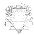
- FIG. 1 is a vertical sectional front view showing a schematic configuration of a combination weighing device according to one embodiment of the present invention.
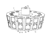
- FIG. 2 is a perspective view of the center base body.
- FIG. 3 is a perspective view of a drive unit for the feed hopper.
- FIG. 4 is a perspective view of a drive unit for a weigh hopper.
- FIG. 5 is a perspective view of the supply hopper assembled to the drive unit, as viewed from the right.
- FIG. 6 is a perspective view of the supply hopper assembled to the drive unit, as viewed from the left.
- FIG. 7 is a perspective view of the weighing hopper assembled to the drive unit, as viewed from the right.
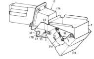
- FIG. 8 is a perspective view of the weighing hopper assembled to the drive unit, as viewed from the left.
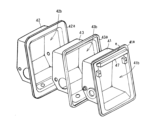
- FIG. 9 is an exploded perspective view of the housing of the drive unit for the supply hopper.
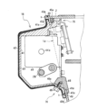
- FIG. 10 is a cross-sectional side view of the drive unit for the feed hopper.
- FIG. 11 is an enlarged longitudinal sectional view of a main portion in an exploded state.
- FIG. 12 is an enlarged longitudinal sectional view of the main parts in an assembled state.
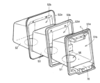
- FIG. 13 is an exploded perspective view of an upper housing of a drive unit for a weighing hopper.
- FIG. 14 is a vertical cross-sectional side view of a drive unit for a weighing hopper.
- FIG. 15 is a side view showing a part of a drive unit for a weighing hopper in vertical section.
- FIG. 16 is an enlarged vertical cross-sectional view of a portion of the waterproof structure.
- FIG. 1 is a vertical cross-sectional front view showing the schematic configuration of a combination weighing device according to one embodiment of the present invention.
- the combination weighing device of this embodiment weighs and discharges predetermined amounts of various foods, snacks, and other items.
- This combination weighing device is installed on floor F on an upper floor of a frame assembled like a tower that workers can climb up and down. Items within a predetermined weight range weighed by the combination weighing device are fed into a packaging device (not shown) installed on the floor below and packaged.
- a hollow base 1 with a large opening in the vertical direction at the center is installed on the floor surface F.
- a hollow center base 2 formed in the shape of a polygonal short pillar is supported by multiple legs 3 at the upper center of this base 1.
- a dispersion feeder 4 is installed above the center of the center base 2.
- the dispersion feeder 4 receives items dropped from a supply conveyor (not shown) with a vibration-driven top cone 4a and distributes and transports them radially.
- a number of linear feeders 5 are arranged radially around the dispersion feeder 4, which transport the items dispersed and transported by the dispersion feeder 4 in a straight line outward with vibration-driven troughs 5a.
- the outer peripheral wall of the center base 2 is equipped with a supply hopper 6 that temporarily stores and discharges the items transported by each linear feeder 5, and a weighing hopper 7 that receives the items discharged from each supply hopper 6 and weighs them.
- a multiple-series weighing unit is formed by a series of these linear feeders 5, supply hoppers 6, and weighing hoppers 7.
- a control device installed in the center base 2 controls each section and performs a combination calculation based on the weight values of the items weighed by the weighing hoppers 7 to select a combination of weighing hoppers 7 in which the weight of the items falls within a specified weight range.
- this combination calculation one appropriate combination is selected in which the combined weight value obtained by combining the weight values of the items of the multiple weighing hoppers 7 in various ways is equal to the target combined weight value, or is the weight value closest to the target combined weight value within a specified weight range with the target combined weight value as the lower limit weight value.
- the control device discharges items from the weighing hopper 7 that has been selected as the appropriate combination.
- a collection chute 8 is provided below each weighing hopper 7, which guides the items discharged from the multiple weighing hoppers 7 selected as the appropriate combination downward toward the center of the device.
- a collection funnel 9 is provided below and in the center of the collection chute 8, which collects the items that have flowed down along the collection chute 8 toward the center of the device, and a collection hopper 10 is provided to temporarily hold the collected items and is controlled to open based on a discharge command from the packaging device.
- a vibration mechanism 11 is installed in the center of the interior of the center base 2.
- the top cone 4a of the dispersion feeder 4 is detachably connected to the drive shaft 11a of the vibration mechanism 11, which is protruding from the top surface of the center of the base, and the top cone 4a is driven to vibrate.
- This vibration mechanism 11 is mounted and supported by a weight detection unit 12, and the operation of a supply conveyor (not shown) is controlled based on the detected weight information so that there are always articles on the dispersion feeder 4 within a specified weight range.
- multiple vibration mechanisms 13 are arranged inside the center base 2 so as to surround the vibration mechanism 11.
- the troughs 5a of the linear feeder 5 are detachably connected to the vibration heads 13a of the vibration mechanisms 13 protruding from the top surface of the base, and each trough 5a is vibrated.
- the outer periphery of the center base 2 has two upper and lower tiers of openings 14, 15 for assembling multiple drive units.
- a drive unit 16 that drives the gate of the supply hopper 6 to open and close is assembled and fixed to the upper tier opening 14.
- a drive unit 17 that drives the gate of the weighing hopper 7 to open and close and also has a weight detection unit is assembled and fixed to the lower tier opening 15.
- the supply hopper 6 is detachably attached to the drive unit 16, and the weighing hopper 7 is detachably attached to the drive unit 17.
- the structure of the supply hopper 6 and weighing hopper 7, and their mounting structure will be explained.
- the side toward the center of the center base 2 will be referred to as the front, and the side away from the center base 2 will be referred to as the rear.
- Fig. 3 is an oblique view of the drive unit 16 for the supply hopper that drives the opening and closing of the gate of the supply hopper 6
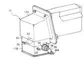
- Fig. 4 is an oblique view of the drive unit 17 for the weighing hopper that drives the opening and closing of the gate of the weighing hopper 7.
- Fig. 5 is an oblique view of the supply hopper 6 assembled to the drive unit 16 as seen from one side in the left-right direction (the right)
- Fig. 6 is an oblique view of the supply hopper 6 assembled to the drive unit 16 as seen from the other side in the left-right direction (the left).
- a pair of left and right mounting brackets 20 are welded and fixed to the left and right outer lateral surfaces of the supply hopper 6, and extend forward.
- the inner gate 21a and outer gate 21b of the supply hopper 6 are attached to the mounting brackets 20 so that they can rotate around fulcrums a and b, respectively.
- the inner and outer gates 21a and 21b are linked together by a link 22.
- the outer gate 21b is rotated open and closed in conjunction with the inner gate 21a being driven and opened/closed.
- a downward recess 23 is formed at the forward extending end of the mounting bracket 20. This recess 23 engages from above with bosses 24 protruding from the left and right outer lateral faces of the drive unit 16, and the inner corners of each mounting bracket 20 are engaged with support pins 25 protruding from the left and right outer lateral faces of the drive unit 16 so that they rest on each other. In this way, the entire supply hopper 6 is positioned and supported in a fixed posture by the drive unit 16 with four locking points, two on each side.
- an operating arm 26 is attached to one of the mounting brackets 20 shown in FIG. 5 so as to be rotatable around a fulcrum p.
- This operating arm 26 and the inner gate 21a are linked via an operating link 27.
- Both gates 21a and 21b are rotated open and closed in conjunction with the reciprocating rotation of the operating arm 27.
- a drive shaft 28 protruding from one of the boss portions 24 is provided on one lateral outer side of the drive unit 16.
- a drive arm 29 that rotates by the drive shaft 28 is connected to the drive shaft 28.
- a drive pin 29a is attached to the tip of the drive arm 29, and the free end of the operating arm 26 is engaged with this drive pin 29a from above.
- a gate drive structure is configured that opens and closes the inner and outer gates 21a, 21b of the supply hopper 6 by rotating the drive arm 29 back and forth at a predetermined angle.
- the structure and mounting structure of the weighing hopper 7 are basically the same as the supply hopper 6 described above.
- Figure 7 is a perspective view of the weighing hopper 7 assembled to the drive unit 17 as seen from one side in the left-right direction (the right), and Figure 8 is a perspective view of the weighing hopper 7 assembled to the drive unit 17 as seen from the other side in the left-right direction (the left).
- the drive unit 17 for the weighing hopper includes an upper unit 17A that houses a weight sensor, and a lower unit 17B that drives the opening and closing of the gate of the weighing hopper 7.
- a pair of left and right mounting brackets 30 are welded and fixed to the left and right outer lateral surfaces of the weighing hopper 7, and extend forward.
- the inner gate 31a and outer gate 31b of the weighing hopper 7 are attached to the mounting brackets 30 so that they can rotate around fulcrums c and d, respectively.
- the inner and outer gates 31a and 31b are linked together by a link 32, so that the outer gate 31b is opened and closed in conjunction with the inner gate 31a being driven and opened.
- a downward recess 33 is formed at the forward extending end of each mounting bracket 30.
- This recess 33 engages from above with bosses 34 protruding from the left and right outer lateral faces of the lower unit 17B, and the inner corners of each bracket 30 engage with support pins 35 protruding from the outer lateral faces of the lower unit 17B so that they rest on each other. This allows the entire weighing hopper 7 to be positioned and supported in a fixed posture on the lower unit 17B with four locking points, two on each side.
- an operating arm 36 is attached to the right mounting bracket 30 shown in Figure 7 so that it can rotate around a fulcrum q.
- This operating arm 36 and the inner gate 31a are linked via an operating link 37, so that both gates 31a, 31b rotate open and closed in conjunction with the reciprocating rotation of the operating arm 37.
- a drive shaft 38 protruding from one of the boss portions 34 is provided on one outer lateral side of the lower unit 17B.
- a drive arm 39 that rotates by the drive shaft 38 is connected to this drive shaft 38.
- a drive pin 39a is attached to the tip of the drive arm 39. The free end of the operating arm 36 is adapted to engage with this drive pin 39a from above.
- a gate drive structure is configured that opens and closes the inner and outer gates 31a, 31b of the weighing hopper 7 by rotating the drive arm 39 back and forth at a predetermined angle.
- the product zone In combination weighing devices that handle food as an item, for hygienic reasons, the area that the item comes into direct contact with, or the area directly above the item, is designated as the product zone. Equipment components and areas in this product zone must be cleaned at appropriate times to remove any remaining residue.
- the top cone 4a of the dispersion feeder 4, the trough 5a of the linear feeder 5, the supply hopper 6, and the weighing hopper 7 are removed and washed individually, and the center base 2, etc. exposed by removing these, are washed with high-pressure cleaning water.
- the protruding portion of the drive shaft 11a, where the top cone 4a of the dispersion feeder 4 is attached and detached, is provided with a known waterproof structure using a seal ring, and the protruding portion of the vibration head 13a, where the trough 5a of the linear feeder 5 is attached and detached, is provided with a known waterproof structure using a bellows.
- This embodiment is characterized by the waterproof structure of the drive units 16 and 17, the detailed structure of which will be explained below with reference to the drawings.
- Figure 9 shows an exploded perspective view of the housing that constitutes the drive unit 16 of the supply hopper 6, and Figure 10 shows a vertical cross-sectional side view of the drive unit 16 connected to the center base 2.
- the housing of this drive unit 16 comprises a metal unit case 41 with a large opening 41b facing forward toward the center base 2, and a metal cover case 42 that completely covers the unit case from the outside.
- the unit case 41 in this embodiment is made of die-cast metal such as aluminum alloy, which can be molded into any shape.
- the cover case 42 that forms the outer periphery of the housing is made of a rust-resistant metal such as stainless steel or brass that is resistant to corrosion, and in this embodiment, is made of stainless steel plate.
- Gaps are likely to occur between the die-cast unit case 41 and the sheet metal cover case 42 that covers it.
- the housing of the drive unit 16 is located in the product zone above the collecting chute 8, which guides the flow of food and other items discharged from the weighing hopper 7. As described above, it is washed with cleaning water at appropriate times, so it is necessary to prevent water from entering the gap between the unit case 41 and the cover case 42 and to prevent bacteria from growing in the gap.
- a covering packing 43 that covers the outer surface of the unit case 41 is sandwiched between the unit case 41 and the cover case 42.
- This covering packing 43 is made of an elastic sealing material such as synthetic rubber, and is case-shaped (box-shaped) with one end open, just like the unit case 41 and the cover case 42.
- the covering gasket 43 fills the gap formed between the unit case 41 and the cover case 42, preventing the infiltration of cleaning water and preventing the growth of bacteria in the gap.
- the unit case 41 has a flange portion 41a that abuts against the outer peripheral surface of the center base 2 around the entire circumference of the forward-facing opening 41b.
- the covering packing 43 that covers the unit case 41 also has a large forward-facing opening 43b, and around the entire circumference of this opening 43b, as shown in FIG. 10, there is a folded flange portion 43a that fits around the outer peripheral portion of the flange portion 41a of the unit case 41.
- the cover case 42 that covers the covering packing 43 also has a large forward-facing opening 42b, and around the entire circumference of this opening 42b, there is a flange portion 42a that covers and hides the folded flange portion 43a of the covering packing 43 from the outer periphery.
- the flange portion 42a of the cover case 42 is provided outside the outer periphery of the folded flange portion 43a, and a gap s is formed between the flange portion 42a and the folded flange portion 43a in a ring shape along the circumferential direction.
- the front edge of the flange portion 42a of the cover case 42 is slightly separated from the outer peripheral surface of the center base 2. This prevents the front edge of the flange portion 42a from abutting against the outer peripheral surface of the center base 2 before the front end surface of the flange portion 41a of the unit case 41 abuts against the outer peripheral surface of the center base 2.
- a step e for mounting a packing is formed around the entire periphery of the front end surface of the flange portion 41a.
- the depth of this step e is set slightly smaller than the thickness of the front portion of the folded flange portion 43a.
- the front portion of the folded flange portion 43a fitted onto the flange portion 41a protrudes slightly from the front end surface of the flange portion 41a as shown in FIG. 11.
- this protrusion amount becomes the elastic tightening margin when the unit case 41 is attached to the center base body 2.
- the front portion of the folded flange portion 43a functions as a packing when the drive unit 16 of the center base body 2 is attached as shown in FIG. 12, and waterproofing is achieved at the opening 14 of the center base body 2 and the opening 41b of the unit case 41 of the drive unit 16.
- IP69K As stipulated in German Industrial Standard DIN 40050 Part 9, is required. IP69K requires that 80°C hot water be sprayed from a nozzle of a specified shape from a distance of 10-15 cm, with a water pressure of 80-100 bar and a water flow rate of 14-16 liters per minute.
- a shielding protrusion 49 is welded to the outer circumferential surface of the center base 2 in an annular shape, surrounding the opening 14, and enters the annular gap s formed between the folded flange portion 43a of the coating packing 43 and the flange portion 42a of the cover case 42.
- the shielding protrusion 49 is made of, for example, stainless steel, and protrudes between the flange portion 42a of the cover case 42 and the folded flange portion 42a of the coating packing 43 in the gap s.
- the cleaning water that penetrates into the inside of the flange portion 42 through the gap between the outer peripheral surface of the center base 2 and the front edge of the flange portion 42a is guided to the bottom of the drive unit 16 through the annular gap s formed between the flange portion 42a and the folded flange portion 43a, and is discharged to the outside through the gap between the outer peripheral surface of the center base 2 and the front edge of the flange portion 42a.
- the shielding protrusion 49 is preferably formed in a ring shape around the entire circumference of the opening 14, but part of the ring shape, for example the lower part, may be omitted.
- a stepping motor 44 is mounted sideways as an actuator for opening and closing the gate of the supply hopper 6, and the motor output shaft 44a is linked via a link mechanism to the drive shaft 28 which is connected to the drive arm 29 for opening and closing the gate.
- the housing of the drive unit 16 shown in FIG. 9 is assembled by fitting the cover case 42, the cover packing 43 through the opening 42b, and the unit case 41 through the opening 43b of the cover packing 43, that is, the cover case 42, the cover packing 43, and the unit case 41, which have similar external shapes and successively smaller external dimensions, are nested together.
- the entire outer surface of the unit case 41 is covered by the case-shaped covering gasket 43, and the entire outer surface of the covering gasket 43 is covered by the cover case 42.
- adhesive can be applied to the inside of the folded flange portion 43a of the covering packing 43 and then fitted into the flange portion 41a of the unit case 41, thereby integrating the unit case 41 and the covering packing 43.
- adhesive can be applied to an appropriate location on the outer surface of the covering packing 43, for example, the rearward facing outer surface of the folded flange portion 43a, and the cover case 42 can be fitted in, thereby integrating the housing of the drive unit 16 into a three-layer structure.
- a support member 45 having an inclined surface 45a is welded to the inside of the upper edge of the opening 14 in the center base 2.
- a pair of left and right mounting blocks 46 having downward inclined surfaces 46a are welded to the lower edge of the opening 14.
- a connecting protrusion 47 having an inclined surface 47a and protruding diagonally upward is provided at the top of the forward-facing opening 41b in the unit case 41.
- the bottom of the center base 2 and the unit case 41 form a connecting portion 76 where the mounting block 46 with the downward inclined surface 46a and the unit case 41 are fastened and connected by the bolt 48 as a fastening member.
- the drive unit 16 is pushed up by the lower part of the unit case 41 being pressed against the downward inclined surface 46a of the mounting block 46 with bolts, which causes the inclined surface 47a of the connecting projection 47 to be tightly engaged with the inclined surface 45a of the support member 45 by a wedge action.
- the drive unit 16 can be firmly connected and fixed without rattling by simply tightening the bolts at two points on the lower part of the unit.
- the drive unit 16 can be attached to the center base 2 simply by fastening the two bolts 48 to the mounting block 46 at two points on the left and right sides of the lower part of the unit case 41.
- Figure 13 shows an exploded perspective view of part of the housing that constitutes the drive unit 17 of the weighing hopper 7, and Figures 14 and 15 show vertical side views of the drive unit 17 connected to the center base 2.
- the housing that constitutes the upper unit 17A of the drive unit 17 is composed of a unit case 51 made of die-cast metal such as an aluminum alloy with a large opening 51b facing forward, which is the center base 2 side, a cover case 52 made of stainless steel plate, which is a rust-resistant metal, that covers the entire unit case 51 from the outside, and a coating packing 53 made of an elastic sealing material that is sandwiched between the unit case 51 and the cover case 52.
- the case-shaped covering gasket 53 that covers the outer surface of the unit case 51 fills the gap between the unit case 51 and the cover case 52, preventing the infiltration of cleaning water and preventing the growth of bacteria in this area.
- the unit case 51 has a flange portion 51a that abuts against the outer peripheral surface of the center base 2 around the entire circumference of an opening 51b facing forward.
- the covering packing 53 that covers the unit case 51 also has a large opening 53b facing forward, and around the entire circumference of this opening 53b, there is a folded flange portion 53a that fits around the outer peripheral portion of the flange portion 51a of the unit case 51.
- the cover case 52 that covers the covering packing 53 also has a large opening 52b facing forward, and around the entire circumference of this opening 52b, there is a flange portion 52a that covers and hides the folded flange portion 53a of the covering packing 53 from the outer periphery.
- a step f is formed around the entire circumference of the front end surface of the flange portion 51a of the unit case 51, onto which the folded flange portion 53a of the covering packing 53 is fitted.
- the front end of the folded flange portion 53a fitted onto this step f protrudes slightly from the mounting front end surface of the flange portion 51a. Therefore, the amount of protrusion of the front end of the folded flange portion 53a becomes the elastic tightening margin when the drive unit 17 is attached to the center base 2, and the opening 15 of the center base 2 and the opening of the upper unit 17A are waterproofed.
- the flange portion 52a of the cover case 52 is provided outside the outer periphery of the folded flange portion 53a, as shown in FIG. 14, and an annular gap t is formed between the flange portion 52a and the folded flange portion 53a, which serves as a drainage flow path for cleaning water that has infiltrated inside the flange.
- annular shielding protrusion 59 that fits into the gap t is welded to the outer peripheral surface of the center base 2, surrounding the opening 15.
- the shielding protrusion 59 be formed in a ring shape around the entire circumference of the opening 15, but part of the ring shape may be omitted.
- a load cell 54 serving as a weight sensor is connected and fixed in a cantilever shape inside the upper unit 17A, and a support block 55 is connected to the free end of the load cell 54 for applying a weight load.
- the lower end of the support block 55 faces a lower opening 56 formed in the lower surface of the upper unit 17A, and the lower unit 17B is connected and supported to the lower end of the support block 55, as shown in FIG. 15.
- the weight of the entire lower unit 17B to which the weighing hopper 7 is attached is applied to the free end of the load cell 54 via the support block 55, and the strain deformation of the load cell 54 is electrically detected via a strain gauge, thereby measuring the weight of the items contained in the weighing hopper 7.
- the housing of the lower unit 17B has a three-layer structure consisting of a unit case 61 made of die-cast aluminum with an open bottom, a cover case 62 made of stainless steel plate that covers the outer periphery of the unit case 61, and a coating packing 63 made of an elastic sealing material that is sandwiched between the unit case 61 and the cover case 62, and the lower opening is closed by a bottom cover 64.
- a skirt-shaped waterproof cover 65 that covers the lower opening 56 is connected and fixed to the underside of the upper unit 17A. As shown in FIG. 16, the annular gap formed between this waterproof cover 65 and the upper end of the lower unit 17B is blocked by a ring-shaped bellows 66. This ensures that the opening 56 on the underside of the upper unit 17A is waterproofed while allowing vertical displacement of the lower unit 17B due to fluctuations in the load.
- a servo motor 67 that acts as an actuator for opening and closing the gate is attached to the upper unit 17B so as to protrude forward.
- the motor output shaft 67a is linked to the drive shaft 38 of the drive arm 39 that opens and closes the gate of the weighing hopper 7 via a link linkage mechanism (not shown).
- a pair of left and right mounting blocks 68 having upwardly inclined surfaces 68a are welded to the upper edge of the opening 15 in the center base 2.
- a support member 69 is welded to the lower edge of the opening 15.
- a connecting protrusion 70 having an inclined surface 70a that protrudes toward the center base 2 is provided at the bottom of the inward opening of the unit case 51.
- the lower part of the center base 2 and the unit case 51 is provided with an engagement portion 77 where the inclined surface 69a of the support member 69 of the center base 2 and the inclined surface 70a of the connecting protrusion 70 of the unit case 51 engage with each other.
- the upper part of the center base 2 and the unit case 51 is provided with a connecting portion 78 where the mounting block 68 with the upward inclined surface 68a and the unit case 51 are fastened and connected with a bolt 71 as a fastening member.
- the upper part of the unit case 51 is pressed against the upwardly inclined surface 68a of the mounting block 68 with a bolt, which presses the drive unit 17 downward, thereby firmly engaging the inclined surface 70a of the connecting projection 70 with the inclined surface 69a of the support member 69 through a wedge action.
- the drive unit 17 can be firmly connected and fixed without any rattling, simply by tightening the bolts at the top.
- the weighing hopper 7's drive unit 17 is heavy because it is fitted with the load cell 54 and the servo motor 67 as an actuator for opening and closing the gate.
- This heavy drive unit 17 is first placed on the lower engagement portion 77, and then engaged, so that the weight of the drive unit 17 is temporarily placed on the center base 2, and then the bolt tightening operation is performed at the upper connection portion 78. This makes it unnecessary to lift the drive unit 17 while performing the bolt tightening operation, making the installation of the drive unit 17 easier.
- the drive unit 16 for the supply hopper 6 and the drive unit 17 for the weighing hopper 7 are configured separately and attached individually to the center base 2. Therefore, for example, if a malfunction occurs in the gate drive system of the supply hopper 6 or the weighing hopper 7, or if a malfunction occurs in the weight measurement system of the weighing hopper 7, it is sufficient to remove one of the drive units in response to the malfunction and carry out the desired repair procedure, making maintenance easier than if the supply hopper 6 and the weighing hopper 7 were equipped with a common drive unit.
- the drive unit 16 of the supply hopper 6 and the drive unit 17 of the weighing hopper 7 are configured separately and attached individually to the center base 2, but it is also possible to implement a configuration in which the supply hopper 6 and the weighing hopper 7 are attached to a common drive unit.
- the combination weighing device has a circular arrangement in which multiple series of weighing units consisting of linear feeders, supply hoppers, and weighing hoppers are arranged in a circle around a dispersion feeder.
- the combination weighing device may be a horizontal type combination weighing device in which multiple series of weighing units consisting of linear feeders, supply hoppers, and weighing hoppers are arranged in parallel in a horizontal row and connected to a horizontally long center base.
- the folded flange portions 43a, 53a of the covering packings 42, 52 that fill the gap between the unit cases 41, 51 and the cover cases 42, 52 are used as packing that is sandwiched between the outer peripheral surface of the center base 2 and the mounting end faces of the unit cases 41, 51.
- the entire gap between the unit case 41, 51 and the cover case 42, 52 is filled with the covering packing 42, 52 to provide a waterproof structure.
Landscapes
- Physics & Mathematics (AREA)
- General Physics & Mathematics (AREA)
- Basic Packing Technique (AREA)
- Filling Or Emptying Of Bunkers, Hoppers, And Tanks (AREA)
Priority Applications (3)
| Application Number | Priority Date | Filing Date | Title |
|---|---|---|---|
| EP23934080.5A EP4700339A1 (en) | 2023-04-20 | 2023-04-20 | Waterproof structure of combination weighing device |
| PCT/JP2023/015757 WO2024218935A1 (ja) | 2023-04-20 | 2023-04-20 | 組合せ計量装置の防水構造 |
| JP2025514989A JP7812191B2 (ja) | 2023-04-20 | 2023-04-20 | 組合せ計量装置の防水構造 |
Applications Claiming Priority (1)
| Application Number | Priority Date | Filing Date | Title |
|---|---|---|---|
| PCT/JP2023/015757 WO2024218935A1 (ja) | 2023-04-20 | 2023-04-20 | 組合せ計量装置の防水構造 |
Publications (1)
| Publication Number | Publication Date |
|---|---|
| WO2024218935A1 true WO2024218935A1 (ja) | 2024-10-24 |
Family
ID=93152208
Family Applications (1)
| Application Number | Title | Priority Date | Filing Date |
|---|---|---|---|
| PCT/JP2023/015757 Ceased WO2024218935A1 (ja) | 2023-04-20 | 2023-04-20 | 組合せ計量装置の防水構造 |
Country Status (3)
| Country | Link |
|---|---|
| EP (1) | EP4700339A1 (https=) |
| JP (1) | JP7812191B2 (https=) |
| WO (1) | WO2024218935A1 (https=) |
Citations (7)
| Publication number | Priority date | Publication date | Assignee | Title |
|---|---|---|---|---|
| JPH02167434A (ja) * | 1988-09-07 | 1990-06-27 | Ishida Scales Mfg Co Ltd | 防水型自動計量装置 |
| JPH09270277A (ja) * | 1996-04-02 | 1997-10-14 | Oki Electric Ind Co Ltd | 電装品用防水ケース |
| JP2001349769A (ja) * | 2000-06-08 | 2001-12-21 | Anritsu Corp | 計量装置 |
| US6365845B1 (en) * | 1999-11-16 | 2002-04-02 | Triangle Package Machinery Company | Sanitary weighing machine |
| JP2006147868A (ja) * | 2004-11-19 | 2006-06-08 | Canon Electronics Inc | カバーのシール構造 |
| JP2011163957A (ja) | 2010-02-10 | 2011-08-25 | Yamato Scale Co Ltd | 扉の防水構造および計量装置 |
| WO2021210167A1 (ja) * | 2020-04-17 | 2021-10-21 | 大和製衡株式会社 | ホッパ取付け構造及びそれを備えた計量装置 |
-
2023
- 2023-04-20 EP EP23934080.5A patent/EP4700339A1/en active Pending
- 2023-04-20 WO PCT/JP2023/015757 patent/WO2024218935A1/ja not_active Ceased
- 2023-04-20 JP JP2025514989A patent/JP7812191B2/ja active Active
Patent Citations (7)
| Publication number | Priority date | Publication date | Assignee | Title |
|---|---|---|---|---|
| JPH02167434A (ja) * | 1988-09-07 | 1990-06-27 | Ishida Scales Mfg Co Ltd | 防水型自動計量装置 |
| JPH09270277A (ja) * | 1996-04-02 | 1997-10-14 | Oki Electric Ind Co Ltd | 電装品用防水ケース |
| US6365845B1 (en) * | 1999-11-16 | 2002-04-02 | Triangle Package Machinery Company | Sanitary weighing machine |
| JP2001349769A (ja) * | 2000-06-08 | 2001-12-21 | Anritsu Corp | 計量装置 |
| JP2006147868A (ja) * | 2004-11-19 | 2006-06-08 | Canon Electronics Inc | カバーのシール構造 |
| JP2011163957A (ja) | 2010-02-10 | 2011-08-25 | Yamato Scale Co Ltd | 扉の防水構造および計量装置 |
| WO2021210167A1 (ja) * | 2020-04-17 | 2021-10-21 | 大和製衡株式会社 | ホッパ取付け構造及びそれを備えた計量装置 |
Also Published As
| Publication number | Publication date |
|---|---|
| JP7812191B2 (ja) | 2026-02-09 |
| JPWO2024218935A1 (https=) | 2024-10-24 |
| EP4700339A1 (en) | 2026-02-25 |
Similar Documents
| Publication | Publication Date | Title |
|---|---|---|
| US9234787B2 (en) | Actuator mount for a combination weigher | |
| EP0125902B1 (en) | Hopper for use in an automatic weighing apparatus | |
| JPWO1998001727A1 (ja) | ホッパの着脱性を改善した計量装置 | |
| JP7812191B2 (ja) | 組合せ計量装置の防水構造 | |
| JP6386105B2 (ja) | 計量包装システム | |
| US6365845B1 (en) | Sanitary weighing machine | |
| JP7812190B2 (ja) | 組合せ計量装置の防水構造 | |
| JP7816911B2 (ja) | 組合せ計量装置の防水構造 | |
| US4809795A (en) | Support frame-free hopper-type weighing device for extruders | |
| JP2010519476A (ja) | 上薬で被覆された化学反応装置のための貯留区域無し扁平台座付きで上方開口部を有する排出用集合体 | |
| EP4119471B1 (en) | Seal structure and weighing machine comprising same | |
| JP2011163957A (ja) | 扉の防水構造および計量装置 | |
| US20020157875A1 (en) | Combination weighing equipment | |
| JP4566340B2 (ja) | 計量装置 | |
| JP4721818B2 (ja) | 点検窓 | |
| JP6016427B2 (ja) | 脱穀装置 | |
| US20180126419A1 (en) | Vibrating apparatus and method of improving the durability of a vibrating apparatus | |
| JP3836972B2 (ja) | 振動ふるい機 | |
| JP7537854B2 (ja) | ホッパ及び組合せ秤 | |
| CN215556879U (zh) | 犁式卸料器防积煤落料装置 | |
| JP2000289798A (ja) | 粉体受入排出ホッパ及びそれを使用した粉体受入排出装置 | |
| JP3294129B2 (ja) | 脱穀装置のシーブケース構造 | |
| JP7140676B2 (ja) | 収穫機 | |
| JP7474473B2 (ja) | 計量機構 | |
| JP2006038720A (ja) | 組合せ秤 |
Legal Events
| Date | Code | Title | Description |
|---|---|---|---|
| 121 | Ep: the epo has been informed by wipo that ep was designated in this application |
Ref document number: 23934080 Country of ref document: EP Kind code of ref document: A1 |
|
| ENP | Entry into the national phase |
Ref document number: 2025514989 Country of ref document: JP Kind code of ref document: A |
|
| WWE | Wipo information: entry into national phase |
Ref document number: 2025514989 Country of ref document: JP |
|
| WWE | Wipo information: entry into national phase |
Ref document number: 2023934080 Country of ref document: EP |
|
| NENP | Non-entry into the national phase |
Ref country code: DE |
|
| ENP | Entry into the national phase |
Ref document number: 2023934080 Country of ref document: EP Effective date: 20251120 |
|
| ENP | Entry into the national phase |
Ref document number: 2023934080 Country of ref document: EP Effective date: 20251120 |
|
| ENP | Entry into the national phase |
Ref document number: 2023934080 Country of ref document: EP Effective date: 20251120 |
|
| ENP | Entry into the national phase |
Ref document number: 2023934080 Country of ref document: EP Effective date: 20251120 |
|
| ENP | Entry into the national phase |
Ref document number: 2023934080 Country of ref document: EP Effective date: 20251120 |
|
| ENP | Entry into the national phase |
Ref document number: 2023934080 Country of ref document: EP Effective date: 20251120 |
|
| ENP | Entry into the national phase |
Ref document number: 2023934080 Country of ref document: EP Effective date: 20251120 |
|
| ENP | Entry into the national phase |
Ref document number: 2023934080 Country of ref document: EP Effective date: 20251120 |
|
| ENP | Entry into the national phase |
Ref document number: 2023934080 Country of ref document: EP Effective date: 20251120 |
|
| WWP | Wipo information: published in national office |
Ref document number: 2023934080 Country of ref document: EP |