WO2024214203A1 - 回転電機、その回転電機と電力駆動装置とを組み合わせた回転電機システム、およびその回転電機システムを搭載した電動車 - Google Patents
回転電機、その回転電機と電力駆動装置とを組み合わせた回転電機システム、およびその回転電機システムを搭載した電動車 Download PDFInfo
- Publication number
- WO2024214203A1 WO2024214203A1 PCT/JP2023/014826 JP2023014826W WO2024214203A1 WO 2024214203 A1 WO2024214203 A1 WO 2024214203A1 JP 2023014826 W JP2023014826 W JP 2023014826W WO 2024214203 A1 WO2024214203 A1 WO 2024214203A1
- Authority
- WO
- WIPO (PCT)
- Prior art keywords
- electric machine
- rotating electric
- stator core
- torque ripple
- rotor
- Prior art date
- Legal status (The legal status is an assumption and is not a legal conclusion. Google has not performed a legal analysis and makes no representation as to the accuracy of the status listed.)
- Ceased
Links
Images










Classifications
-
- H—ELECTRICITY
- H02—GENERATION; CONVERSION OR DISTRIBUTION OF ELECTRIC POWER
- H02K—DYNAMO-ELECTRIC MACHINES
- H02K1/00—Details of the magnetic circuit
- H02K1/06—Details of the magnetic circuit characterised by the shape, form or construction
- H02K1/12—Stationary parts of the magnetic circuit
- H02K1/16—Stator cores with slots for windings
-
- H—ELECTRICITY
- H02—GENERATION; CONVERSION OR DISTRIBUTION OF ELECTRIC POWER
- H02K—DYNAMO-ELECTRIC MACHINES
- H02K21/00—Synchronous motors having permanent magnets; Synchronous generators having permanent magnets
- H02K21/12—Synchronous motors having permanent magnets; Synchronous generators having permanent magnets with stationary armatures and rotating magnets
- H02K21/14—Synchronous motors having permanent magnets; Synchronous generators having permanent magnets with stationary armatures and rotating magnets with magnets rotating within the armatures
- H02K21/16—Synchronous motors having permanent magnets; Synchronous generators having permanent magnets with stationary armatures and rotating magnets with magnets rotating within the armatures having annular armature cores with salient poles
Definitions
- This application relates to a rotating electric machine, a rotating electric machine system that combines the rotating electric machine with an electric drive device, and an electric vehicle equipped with the rotating electric machine system.
- An embedded magnet motor that reduces torque ripple by arranging one auxiliary groove at the tip of the teeth of the stator core in an embedded magnet type distributed winding motor.
- This application discloses technology to solve the problems described above, and aims to provide a rotating electric machine, a rotating electric machine system, and an electric vehicle that can reduce torque ripple of a higher order than slot harmonics, which is often difficult to suppress using motor control.
- the rotating electric machine disclosed in the present application includes a rotor having magnetic poles of a plurality of permanent magnets, and a stator formed by stacking a stator core having a circular core back and a plurality of teeth facing a peripheral surface of the rotor in the axial direction of the rotor, and a winding slot for winding a winding is provided between each of the teeth and the adjacent tooth, and a plurality of auxiliary grooves extending in the stacking direction are arranged on the surfaces of the tips of the teeth facing the rotor, Assuming that the number of magnetic poles of the rotor is P and the number of winding slots is S, the relationship S/P ⁇ 3 is satisfied.
- the rotating electric machine system disclosed in the present application is a combination of the above rotating electric machine and a power drive device that controls the rotation of the rotating electric machine and suppresses torque ripple of the rotating electric machine.
- the electric vehicle disclosed in the present application is equipped with the above-described rotating electric machine system.
- a rotating electric machine capable of reducing torque ripples of orders higher than slot harmonics, which are often difficult to suppress by motor control can be obtained.
- the rotating electric machine system disclosed in the present application it is possible to obtain a rotating electric machine system capable of reducing torque ripples of orders higher than slot harmonics, which are often difficult to suppress by motor control.
- an electric vehicle can be obtained that is equipped with a rotating electric machine system that can reduce torque ripples of orders higher than slot harmonics, which are often difficult to suppress by motor control.
- FIG. 1 is an axial cross-sectional view of one-eighth of a circumference of a rotating electric machine according to a first embodiment
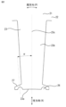
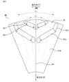
- 2 is an enlarged view of teeth of a stator core of the rotating electric machine according to the first embodiment
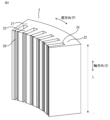
- FIG. 1 is a perspective view of a circumferential eighth of a stator core of a rotating electric machine according to a first embodiment.
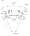
- FIG. 1 is an axial cross-sectional view of one-eighth of a rotor in a circumferential direction of a rotating electric machine according to a first embodiment.
- FIG. 1 is an axial cross-sectional view of one-eighth of a circumferential direction of a stator core (without auxiliary grooves at the tips of teeth) of a rotating electric machine according to embodiment 1; 4 shows an analysis result of 24th-order torque ripple with respect to auxiliary groove position of the rotating electric machine according to embodiment 1.
- 13 is an enlarged view of teeth of a stator core in a modified example (with a rectangular auxiliary groove shape) of the rotating electric machine according to Embodiment 1.
- FIG. 13 is an enlarged view of teeth of a stator core in a modified example (auxiliary groove shape is triangular) of the rotating electric machine according to embodiment 1.
- FIG. 11 is an axial cross-sectional view of a modified example (8-pole, 96-slot, double V-shaped embedded magnet rotor) of the rotating electric machine according to embodiment 1, taken along one-eighth of the circumference.
- FIG. 10 is an axial cross-sectional view of a modified example (six poles, 54 slots, double V-shaped embedded magnet rotor) of the rotating electric machine according to embodiment 1, taken along one-sixth of the circumference.
- FIG. 10 is an axial cross-sectional view of a modified example (8 poles, 48 slots, single V-shaped embedded magnet rotor) of the rotating electric machine according to embodiment 1, taken along one-eighth of the circumference.
- FIG. 10 is an axial cross-sectional view of a modified example (8 poles, 48 slots, single V-shaped embedded magnet rotor) of the rotating electric machine according to embodiment 1, taken along one-eighth of the circumference.
- FIG. 11 is an axial cross-sectional view of a modified example (8 poles, 48 slots, triple V-shaped embedded magnet rotor) of the rotating electric machine according to embodiment 1, taken along one-eighth of the circumference.
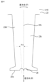
- FIG. 11 is an enlarged view of teeth of a stator core of a rotating electric machine according to a second embodiment.
- FIG. 11 is an enlarged view of teeth of a stator core of a rotating electric machine according to a second embodiment.
- FIG. 11 is a perspective view of a circumferential eighth of a stator core of a rotating electric machine according to a second embodiment.
- FIG. 13 is an explanatory diagram of the phase difference of the 24th-order torque ripple with respect to the auxiliary groove position of the rotating electric machine according to the second embodiment.
- FIG. 13 is a perspective view of one-eighth of a circumferential direction of a stator core of a modified example (change in the ratio of the stator core) of a rotating electric machine according to embodiment 2.
- FIG. FIG. 11 is a perspective view of one-eighth of a circumferential direction of a stator core of a rotating electric machine according to a third embodiment.
- FIG. 11 is a perspective view of one-eighth of a circumferential direction of a stator core of a rotating electric machine according to a fourth embodiment.
- 13 is an enlarged view of a tip portion of a tooth of a stator core of a rotating electric machine according to embodiment 4.
- FIG. 13 is an enlarged view of a tip portion of a tooth of a stator core that is a modified example of a rotating electric machine according to embodiment 4.
- FIG. FIG. 13 is a perspective view of one-eighth of a circumferential direction of a stator core of a rotating electric machine according to embodiment 5.
- FIG. 13 is an axial cross-sectional view of one-eighth of the circumference of a rotating electric machine according to a sixth embodiment.
- FIG. 13 is an axial cross-sectional view of one-eighth of the circumference of a rotating electric machine according to a sixth embodiment.
- FIG. 23 is a perspective view of one-eighth of a circumferential direction of a stator core of a rotating electric machine according to a sixth embodiment.
- FIG. 13 is an axial cross-sectional view of one-eighth of the rotor in the circumferential direction of a rotating electric machine according to embodiment 6.
- FIG. FIG. 13 is an axial cross-sectional view of one-eighth of the circumference of a rotating electric machine according to a sixth embodiment.
- 13 shows the analysis results of 6th to 24th order torque ripple amplitudes of the rotating electric machine according to the sixth embodiment.
- 13 is an analysis result of the amplitude of 18th-order torque ripple with respect to the position of the auxiliary groove of the rotating electric machine according to the sixth embodiment.
- 13 is an explanatory diagram of a phase difference of a rotating electric machine according to a sixth embodiment.
- FIG. 13 is an analysis result of the amplitude of the 24th-order torque ripple with respect to the position of the auxiliary groove of the rotating electric machine according to the sixth embodiment. 13 is an explanatory diagram of a phase difference of a rotating electric machine according to a sixth embodiment.
- FIG. FIG. 1 is a conceptual diagram of an electric vehicle equipped with a rotating electric machine according to a first to sixth embodiments.
- the first embodiment comprises a stator formed by stacking a rotor having multiple permanent magnet poles, a circular core back, and a stator core having multiple teeth facing the peripheral surface of the rotor in the axial direction of the rotor, with winding slots for winding wires being provided between each tooth and its adjacent tooth, and multiple auxiliary grooves extending in the stacking direction being arranged on the surfaces of the tips of the teeth facing the rotor, such that where P is the number of magnetic poles of the rotor and S is the number of winding slots, S/P ⁇ 3 is satisfied.
- FIG. 1 is an axial cross-sectional view of one-eighth of the circumference of the rotating electric machine
- FIG. 2 which is an enlarged view of the teeth of a stator core of the rotating electric machine
- FIG. 3 which is a perspective view of one-eighth of the circumference of a stator core of the rotating electric machine
- FIG. 4 which is an axial cross-sectional view of one-eighth of the circumference of a rotor of the rotating electric machine
- FIG. 5 which is an axial cross-sectional view of one-eighth of the circumference of a stator core of the rotating electric machine (without auxiliary grooves at the tips of the teeth);
- FIG. 1 is an axial cross-sectional view of one-eighth of the circumference of the rotating electric machine
- FIG. 2 which is an enlarged view of the teeth of a stator core of the rotating electric machine
- FIG. 3 which is a perspective view of one-eighth of the circumference of a stator core of the rotating electric
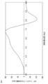
- FIG. 6 which shows the results of an analysis of 24th-order torque ripple with respect to the auxiliary groove position of the rotating electric machine;
- Fig. 7 is an enlarged view of the teeth of a stator core with a modified rotating electric machine (auxiliary groove shaped as a triangle);
- Fig. 8 which is an enlarged view of the teeth of a stator core with a modified rotating electric machine (8-pole, 96-slot, double-V-shaped embedded magnet rotor); Fig.
- axis (direction), diameter (direction), inner diameter (side, direction), outer diameter (side, direction), and circumference (direction) refer to the rotation axis (direction), radius (direction), relatively toward the radial center (side, direction), relatively toward the radial outside (side, direction), and circumference (direction) of the rotation axis in a cylindrical coordinate system centered on the rotation axis of the rotor.
- the rotating electric machine according to the first embodiment is made up of a stator 2 and a rotor 4 that is coaxially arranged radially inside the stator 2 with an air gap 3 interposed therebetween.
- the stator 2 has a stator core 21 made of electromagnetic steel sheets, and the stator core 21 is configured with an annular core back 22 and teeth 23 extending radially inward from the core back 22.
- coils 25 are arranged in winding slots 24, which are areas surrounded by adjacent teeth 23 and the core back 22.
- the winding slots 24 are generally rectangular in shape so that rectangular wire is used for the coils 25.
- the coil 25 is wound around the stator 2 so as to have a distributed winding structure, and is connected in series with the coils 25 arranged in the six adjacent winding slots 24 in the circumferential direction, and a three-phase AC current is passed through the coils 25.
- the direction toward the center of the rotation axis (the vertical direction in Fig. 1) is described as the radial direction (R), and the direction along the rotation direction centered on the rotation axis is described as the circumferential direction (P). The same applies to the following drawings.
- the teeth 23 of the stator core 21 of the rotating electric machine 100 are composed of teeth extensions 23b that extend from the core back 22 so as to become thinner as they go radially inward, and shoes 27 that protrude circumferentially symmetrically from the teeth tips 23a.
- Semicircular auxiliary grooves 26 are arranged on the radially inner surface of the teeth tips 23a at positions that are approximately symmetrical within the dimensional tolerance range with respect to the teeth central axis 23c that passes from the rotation axis of the rotor 4 to the circumferential center point of the teeth tips 23a.
- the auxiliary groove position which is the electrical angle of the angle between the teeth central axis 23c and the straight line connecting the rotation axis of the rotor 4 and the center of the semicircle of the auxiliary groove 26, is ⁇
- the stator 2 of the rotating electric machine 100 includes a stator core 21 in which the above-mentioned electromagnetic steel plates are laminated in the axial direction by a length L.
- the direction of the rotation axis of the rotor 4 (the vertical direction in Fig. 3) is described as the axial direction (X), and the direction along the rotation direction about the rotation axis is described as the circumferential direction (P). The same applies to the following drawings.
- the rotor 4 of the rotating electric machine 100 includes an annular rotor core 41, and a pair of first-layer magnet slots 42f and second-layer magnet slots 42s that are arranged opposite each other so that the distance between them becomes narrower as they move radially inward about the d-axis of the rotor core, which is the main direction of the magnetic flux created by the magnetic poles (i.e., the distance on the radially inner side is narrower than the radially outer side).
- a first-layer permanent magnet 43f and a second-layer permanent magnet 43s are inserted into each of the magnet slots.
- first layer magnet slots 42f and the second layer magnet slots 42s are referred to collectively, they are referred to as magnet slots 42, and when the first layer permanent magnets 43f and the second layer permanent magnets 43s are referred to collectively, they are referred to as permanent magnets 43.
- this rotor structure is referred to as a double V-shaped embedded magnet rotor.
- the permanent magnets 43 are flat, magnetized in parallel along the short side and all facing the same direction in the radial direction. Eight sets of four permanent magnets 43 are arranged in the circumferential direction, with the magnetization direction of adjacent magnets in the circumferential direction facing alternately outward and inward in the radial direction.
- the pole arc angle which is the electrical angle between the two straight lines connecting the center of rotation of the rotor 4 and the d-axis side corners of the magnet slots 42 on the rotor surface side in the rotational direction of the rotor 4
- the pole arc angle of the first layer magnet slots 42f is ⁇ 1
- the pole arc angle of the second layer magnet slots 42s is ⁇ 2.
- Figure 5 is an axial cross-sectional view of one-eighth of the circumference of a third stator core 21C having third teeth 23C with no auxiliary grooves at the tooth tips.
- first teeth 23A the teeth having auxiliary grooves in the vicinity of the central axis of the teeth described in FIG.
- second teeth 23B the stator core and stator including such will be referred to as second stator core 21B and second stator 2B, as appropriate.
- the teeth having no auxiliary grooves are referred to as third teeth 23C, and a stator core and a stator including such teeth are referred to as third stator core 21C and third stator 2C, as appropriate.
- FIG. 6 is a 2D-FEM analysis result showing the change in amplitude of the 24th-order torque ripple with respect to the position of the auxiliary groove 26 of the rotating electric machine according to the first embodiment.
- the change in torque ripple when the auxiliary groove 26 is provided will be explained based on the torque ripple that occurs when the third stator core 21C having the third teeth 23C without the auxiliary groove 26 shown in Figure 5 is used.
- the 24th-order torque ripple has been described, but if the order is greater than the slot harmonics, the auxiliary groove 26 can achieve the torque ripple reduction effect.
- auxiliary groove 26 on each tooth tip 23a at a position symmetrical with respect to the tooth central axis 23c, the number of auxiliary grooves 26 can be minimized, and high torque can be achieved while obtaining the torque ripple reduction effect described above.
- the teeth 23 are densely arranged and the width of the teeth tip 23a is small, so that the degree of difficulty in processing the auxiliary grooves 26, the strength and durability in the vicinity of the auxiliary grooves, etc. can be kept within a relatively reasonable range while obtaining the torque ripple reduction effect of the present embodiment 1.
- auxiliary grooves 26 are arranged on the tooth tip 23a, arranging them symmetrically about the tooth central axis 23c, as shown in the present embodiment 1, is more effective in reducing torque ripple.
- the present embodiment is not limited to a strictly symmetrical arrangement. As long as multiple auxiliary grooves 26 are arranged so that they are distributed approximately evenly around the circumferential direction of the tip of the tooth 23 without any particular bias, the effect of reducing torque ripple in the present embodiment 1 can be achieved to a certain degree.
- auxiliary groove semicircular, the corners of the auxiliary groove 26 are eliminated, improving the mold life and reducing manufacturing costs.
- the rotor 4 in the present embodiment 1 is an embedded magnet type
- the effect of reducing torque ripple in the present embodiment 1 can be obtained even if the pole arc angle ⁇ is not the value shown in the present embodiment 1.
- the rotor 4 in the present embodiment 1 is an embedded magnet type, by changing the pole arc angle ⁇ , the torque ripple of the slot harmonic order and lower orders can be reduced, and the torque ripple of each order can be suppressed in a balanced manner.
- FIG. 7 is an enlarged view of a tooth 23 of a stator core 21 having a rectangular auxiliary groove that is a modification of the rotating electric machine according to Embodiment 1.
- the rectangular auxiliary groove is referred to as auxiliary groove 26s.
- 8 is an enlarged view of a tooth 23 of a stator core 21 having an auxiliary groove with a triangular shape, which is a modification of the rotating electric machine according to Embodiment 1.
- the triangular auxiliary groove is referred to as auxiliary groove 26t.
- FIG. 9 is an axial cross-sectional view of one-eighth of the circumference of a rotating electric machine having an 8-pole, 96-slot, double V-shaped embedded magnet rotor, which is a modified example of the rotating electric machine according to embodiment 1.
- the rotating electric machine is designated as a rotating electric machine 101.
- 10 is an axial cross-sectional view of one-sixth of the circumference of a rotating electric machine having a 6-pole, 54-slot, double V-shaped embedded magnet rotor, which is a modified example of the rotating electric machine according to embodiment 1.
- the rotating electric machine is designated as a rotating electric machine 102.
- FIG. 11 is an axial cross-sectional view of one-eighth of the circumference of an 8-pole, 48-slot, single V-shaped embedded magnet rotor that is a modified example of the rotating electric machine according to embodiment 1.
- FIG. Fig. 12 is an axial cross-sectional view of one-eighth of the circumference of an 8-pole, 48-slot, triple V-shaped embedded magnet rotor, which is a modified example of the rotating electric machine according to embodiment 1.
- Fig. 12 shows a rotating electric machine 103.
- Fig. 12 also shows third layer magnet slots 42t and third layer permanent magnets 43t.
- the auxiliary groove shape of the rotating electric machine according to embodiment 1 is semicircular, but the torque ripple reduction effect described above can be achieved as long as the groove is cut from the tooth tip 23a to the outer periphery, regardless of the shape, such as a square or triangle.
- the triple V-shaped structure of FIG. 12 allows for greater freedom in magnet placement, making it easier to bring the magnetic flux density distribution in the air gap 3 closer to a sine wave.
- the winding slot 24 is made to be approximately rectangular, assuming that a rectangular wire will be used, but the winding slot 24 may be of a shape other than approximately rectangular, and a round wire may be used instead.
- the rotating electric machine of embodiment 1 can change the amplitude of torque ripples larger than slot harmonics and reduce these torque ripples by arranging auxiliary grooves at the tips of the teeth.
- Embodiment 2 has a configuration in which two types of stator cores having different auxiliary groove positions are combined in the axial direction.
- the rotating electrical machine 200 according to the second embodiment is configured by combining two types of stator cores, a first stator core 21A and a second stator core 21B, which have different auxiliary groove positions, in the axial direction.
- the configuration of the rotor 4 is the same as that of the first embodiment.
- the stator core formed by stacking the first stator core 21A and the second stator core 21B is referred to as stator core 21AB.
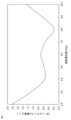
- FIG. 16 shows the phase difference of the 24th-order torque ripple relative to the position of the auxiliary groove 26 in the rotating electric machine 200 according to the second embodiment, based on the phase of the 24th-order torque ripple generated in the third stator core 21C that does not have the auxiliary groove 26.
- Stator core 21AB of embodiment 2 has a different auxiliary groove 26 from stator core 21 of embodiment 1, and so the amplitude of the 24th-order torque ripple when the auxiliary groove position of tooth tip portion 23a is changed is the same as in Fig. 6. And, as shown in Fig. 16, when the auxiliary groove position of tooth tip portion 23a is changed, the phase of the 24th-order torque ripple also changes. 16, the phase difference between the 24th-order torque ripple generated in the first stator core 21A and the second stator core 21B is approximately 180 degrees.
- the 24th-order torque ripple amplitude generated in the first stator core 21A is ⁇ 1 and the 24th-order torque ripple amplitude generated in the second stator core 21B is ⁇ 2
- auxiliary groove 26 on each tooth tip 23a at a position symmetrical about the tooth central axis 23c, the number of auxiliary grooves 26 can be minimized, thereby achieving high torque while obtaining the torque ripple reduction effect described above.
- the teeth 23 are arranged closely together and the width of the tooth tips 23a is small, so that the effect of reducing torque ripple of this embodiment 2 can be obtained while keeping the difficulty of machining the auxiliary groove 26, the strength and durability in the vicinity of the auxiliary groove, and the like, within a relatively reasonable range.
- the torque ripples can be almost completely reduced by combining them in accordance with the ratio of the respective torque ripple amplitudes.
- auxiliary grooves 26 are arranged on tooth tip portion 23a, arranging them symmetrically with respect to tooth central axis 23c as shown in the second embodiment is more effective in reducing torque ripple.
- the aspect of this embodiment 2 is not limited to a strictly symmetrical arrangement, and as long as the multiple auxiliary grooves 26 are arranged so that they are distributed approximately evenly without any particular bias in the circumferential direction of the tooth tip portion 23a, the effect of reducing the torque ripple of this embodiment 2 can be achieved to a certain level.
- auxiliary groove 26 semicircular, the corners of the auxiliary groove 26 are eliminated, improving the mold life and reducing manufacturing costs.
- the rotor 4 in this embodiment is an embedded magnet type
- the effect of reducing torque ripple in this embodiment can be obtained even if the pole arc angle ⁇ is not the value shown in this embodiment.
- the rotor 4 in this embodiment is an embedded magnet type, by changing the pole arc angle ⁇ , the torque ripple of the slot harmonic order and lower orders can be reduced, thereby enabling the torque ripple of each order to be suppressed in a balanced manner.
- the rotor 4 in this embodiment has a double V-shaped structure, there is a high degree of freedom in the arrangement of magnets, and it becomes easy to make the magnetic flux density distribution in the air gap 3 closer to a sine wave.
- FIG. 17 is a perspective view of one-eighth of the circumferential direction of stator core 21AB when the ratio between first stator core 21A and second stator core 21B of rotating electric machine 200 according to the second embodiment is changed.
- two types of stator cores are combined in a ratio that completely suppresses the 24th-order torque ripple, but if they are combined in a ratio that results in a torque ripple amplitude that is smaller than that generated in stator core 21C without auxiliary groove 26, the effect of reducing the 24th-order torque ripple can be obtained.
- the present embodiment illustrates an example of a configuration in which two types of stator cores are combined
- the torque ripple reduction effect of the present embodiment can be obtained even when three or more types of stator cores having different auxiliary groove positions are combined.
- the shape of the auxiliary groove 26 in embodiment 2 was semicircular, but the above-mentioned torque ripple reduction effect can be obtained as long as the structure is cut out from the tooth tip 23a toward the outer periphery regardless of the shape, such as a square or triangle.
- the torque ripple reduction effect of this embodiment can be obtained.
- the rotor structure is a different embedded magnet type, so long as S/P ⁇ 3 is satisfied, the torque ripple reduction effect of this embodiment can be obtained.
- the pole arc angle can be changed, torque ripples of slot harmonic orders and lower orders can also be reduced.
- the rotating electric machine of embodiment 2 can change the amplitude of torque ripples larger than the slot harmonics by arranging auxiliary grooves at the tips of the teeth, thereby reducing these torque ripples. Furthermore, the torque ripple can be reduced by utilizing the phase difference of the torque ripple.
- Embodiment 3 In the third embodiment, two types of stator cores having different auxiliary groove positions are combined in the axial direction so as to be sandwiched by one side.
- FIG. 18 is a perspective view of one-eighth of the circumferential direction of the stator core of the rotating electric machine, focusing on the differences from the first and second embodiments.
- FIG. 18 is a perspective view of one-eighth of the circumferential direction of the stator core of the rotating electric machine, focusing on the differences from the first and second embodiments.
- the same or corresponding parts as those in the first embodiment are denoted by the same reference numerals.
- the third embodiment is referred to as a rotating electric machine 300 .
- FIG. 18 The basic configuration of the rotating electric machine 300 of the third embodiment is the same as that of the second embodiment. However, as shown in Fig. 18, when the stator cores are stacked in the axial direction, the second stator core 21B is sandwiched between the first stator core 21A that is divided into two parts in the axial direction within the range of the dimensional tolerance.
- the structure is axially symmetrical, and in addition to the effects of embodiment 2, it is possible to balance the electromagnetic forces applied to the rotor 4 regardless of its axial position, suppress vibrations, and prevent damage to the bearings. Furthermore, even if the positional relationship between the first stator core 21A and the second stator core 21B is reversed, the same effect can be obtained.
- the rotating electric machine of embodiment 3 can change the amplitude of torque ripples larger than the slot harmonics, thereby reducing these torque ripples. Furthermore, the electromagnetic forces acting on the rotor can be balanced.
- Embodiment 4 is configured by combining a stator core having an auxiliary groove and a stator core having no auxiliary groove 26 .
- the rotating electric machine of embodiment 4 will be described focusing on the differences from embodiment 1, based on Figure 19, which is an oblique view of one-eighth of the circumference of the stator core of the rotating electric machine, Figure 20, which is an enlarged view of the tips of the teeth of the stator core of the rotating electric machine, and Figure 21, which is an enlarged view of the tips of the teeth of a stator core that is a modified example of the rotating electric machine.
- Figure 19 is an oblique view of one-eighth of the circumference of the stator core of the rotating electric machine
- Figure 20 which is an enlarged view of the tips of the teeth of the stator core of the rotating electric machine
- Figure 21 which is an enlarged view of the tips of the teeth of a stator core that is a modified example of the rotating electric machine.
- the fourth embodiment is referred to as a rotating electric machine 400 .
- a rotating electric machine 400 of the fourth embodiment has a configuration in which a first stator core 21A having the auxiliary groove 26 of Fig. 1 is combined with a third stator core 21C having no auxiliary groove 26 of Fig. 5.
- the stator core obtained by stacking the first stator core 21A and the third stator core 21C is referred to as a stator core 21AC.
- the electrical angle of the teeth tip angle on the tooth central axis 23c side (i.e., the circumferential center point side of the teeth tip 23a) across the auxiliary groove 26 of the teeth tip 23a is denoted as ⁇ 1, and the electrical angles of the two teeth tip angles on the circumferential end sides are denoted as ⁇ 2.
- the auxiliary grooves 26 are arranged so that ⁇ 1 ⁇ 2 ⁇ 2 is satisfied.
- the shoe width Wshu is equal to or greater than twice the thickness of the electromagnetic steel sheets constituting the first stator core 21A.
- the amplitude of the 24th-order torque ripple generated in the first stator core 21A is approximately 15% of that in the third stator core 21C. Therefore, when the stator core is configured with only the first stator core 21A as in the first embodiment, the amplitude of the 24th-order torque ripple can be minimized. However, by arranging the auxiliary grooves 26 at the tooth tip portions 23a, the torque decreases compared to when the auxiliary grooves 26 are not provided.
- the 24th-order torque ripple can be reduced more than when constructed with only the third stator core 21C without the auxiliary groove 26, which has a larger 24th-order torque ripple per unit stack thickness.
- the shoe width Wshu is more than twice the thickness of the electromagnetic steel plate that constitutes the first stator core 21A, punching processing using a die is generally possible, improving mass productivity and reducing manufacturing costs.
- the auxiliary grooves 26 are arranged so that ⁇ 1 ⁇ 2 ⁇ 2 as in this embodiment, the phase difference of the torque ripple can be increased as can be seen from FIG. 16, and therefore the torque ripple can be reduced more effectively.
- the auxiliary groove 26 in a semicircular shape, corners of the auxiliary groove 26 can be eliminated, the mold life can be improved, and the manufacturing cost can be reduced.
- the rotor 4 in this embodiment is an embedded magnet type, and by changing the pole arc angle ⁇ , the torque ripple of the slot harmonic order and lower orders can be reduced, thereby enabling the torque ripple of each order to be suppressed in a balanced manner. Furthermore, because the rotor 4 in this embodiment has a double V-shaped structure, there is a high degree of freedom in the arrangement of magnets, and it becomes easy to make the magnetic flux density distribution in the air gap 3 closer to a sine wave.
- Fig. 21 is an enlarged view of tooth tip portions 23a of a first stator core 21A that is a modified example of the rotating electric machine according to embodiment 4. Note that in Fig. 21, the relationship between electrical angles ⁇ 1 and ⁇ 2 of auxiliary grooves 26 described in Fig. 20 is the same. As shown in FIG. 21 , by making the shoe 27 thicker on the outer periphery in the radial direction (R) and making Wshu at least twice the thickness of the electromagnetic steel plate that constitutes the first stator core 21A, it is possible to reduce manufacturing costs while obtaining the effects of reducing torque ripple and increasing torque.
- the torque is smaller than in the fourth embodiment, but it can be made higher than in the first embodiment configured with only the first stator core 21A.
- the phase difference of the torque ripple is greater than 90 degrees, but if the amplitude is smaller than that of the third stator core 21C, the torque ripple reduction effect of embodiment 4 can be obtained to a certain extent even if the phase difference of the torque ripple is less than 90 degrees.
- embodiment 4 illustrates an example of a configuration in which two types of stator cores are combined, the torque ripple reduction effect of embodiment 4 can be obtained even when a third stator core 21C without an auxiliary groove 26 is combined with two or more types of first stator cores 21A having different auxiliary groove positions.
- a third stator core 21C without the auxiliary groove 26 is combined with two types of first stator cores 21A having different auxiliary groove positions, and the phase difference between them is 120 degrees, the torque ripple can be suppressed almost completely.
- the auxiliary groove 26 is arranged so that ⁇ 1 ⁇ 2 ⁇ 2.
- the torque ripple can be reduced, which is the effect of this embodiment.
- auxiliary groove 26 in embodiment 4 was semicircular, but the torque ripple reduction effect of embodiment 4 can be obtained as long as the shape is such that it is cut out from tooth tip 23a to the outer periphery, regardless of the shape, such as a square or triangle.
- the torque ripple reduction effect of this embodiment can be obtained.
- the torque ripple reduction effect of this embodiment can be obtained.
- the pole arc angle can be changed, torque ripples of slot harmonic orders and lower orders can also be reduced.
- Embodiment 5 In the fifth embodiment, the stacking method in the fourth embodiment is modified.
- FIG. 22 is a perspective view of one-eighth of the circumferential direction of the stator core of the rotating electric machine, focusing on the differences from the first and fourth embodiments.
- FIG. 22 is a perspective view of one-eighth of the circumferential direction of the stator core of the rotating electric machine, focusing on the differences from the first and fourth embodiments.
- parts that are the same as or equivalent to those in the first embodiment are given the same reference numerals.
- the fifth embodiment is referred to as a rotating electric machine 500 .
- the basic configuration of the rotating electric machine according to the fifth embodiment is the same as that of the fourth embodiment. However, as shown in FIG. 22, when stacking the stator cores 21AC in the axial direction, the first stator core 21A is sandwiched between the third stator core 21C, which is roughly divided into two in the axial direction within the range of dimensional tolerance.
- the electromagnetic forces acting on the rotor 4 can be balanced regardless of the axial position, thereby reducing vibration and damage to the bearings. Furthermore, by disposing the third stator core 21C, which has no auxiliary groove, at the axial end, magnetic saturation in the shoe 27 of the stator core 21AC is relatively alleviated compared to the shoe 27 of the first stator core 21A, which has the auxiliary groove 26, so that the magnetic flux leaking into the winding slots 24 is reduced and the eddy current loss generated in the coil 25 can be reduced.
- the rotating electric machine of embodiment 5 can change the amplitude of torque ripples larger than the slot harmonics and reduce these torque ripples by arranging auxiliary grooves at the tips of the teeth. Furthermore, the electromagnetic forces acting on the rotor can be balanced.
- Embodiment 6 a first stator core 21A having an auxiliary groove is divided into two and sandwiched between a third stator core 21C having no auxiliary groove, and a notch is provided in the rotor.
- Figures 23 and 24 are axial cross-sectional views of one-eighth of the circumference of the rotating electric machine
- Figure 25 is an oblique view of one-eighth of the circumference of the stator core of the rotating electric machine
- Figure 26 is an axial cross-sectional view of one-eighth of the circumference of the rotor of the rotating electric machine
- Figure 27 is an axial cross-sectional view of one-eighth of the circumference of the rotating electric machine
- Figure 28 which shows the analysis results of the 6th to 24th order torque ripple amplitudes of the rotating electric machine
- Figure 29 which shows the analysis results of the amplitude of the 18th order torque ripple relative to the position of the auxiliary groove of the rotating electric machine
- Figure 30 which is an explanatory diagram of the phase difference of the rotating electric machine
- Figure 31 which is the analysis results of the amplitude of the 24th order torque ripple relative to the position of the auxiliary groove of the rotating electric machine
- FIGS. Fig. 23 is an axial cross-sectional view of one-eighth of the circumference of the rotating electric machine 600, and the basic configuration of the first stator core 21A of the rotating electric machine 600 is the same as that of Fig. 1 of the first embodiment.
- the rotor 4B is provided with a notch 45, the details of which will be described later with reference to Fig. 26.
- Fig. 23 is an axial cross-sectional view of one-eighth of the circumference of the rotating electric machine 600, and the basic configuration of the first stator core 21A of the rotating electric machine 600 is the same as that of Fig. 1 of the first embodiment.
- the rotor 4B is provided with a notch 45, the details of which will be described later with reference to Fig. 26.
- FIG. 24 is an axial cross-sectional view of one-eighth of the circumference of the rotating electric machine 600, and the basic configuration of the third stator core 21C of the rotating electric machine 600 is the same as that of Fig. 5 described in the embodiment 1. However, a notch 45 is provided in the rotor 4B.
- Figure 25 is an oblique view of one-eighth of the circumferential direction of the stator core of the rotating motor 600.
- the stator core 21AC of the rotating motor 600 is stacked such that the first stator core 21A is sandwiched between the third stator core 21C which is divided into two in the axial direction, resulting in an axially symmetrical structure.
- the first stator core 21A has a lamination thickness LA
- the third stator core 21C has a lamination thickness LC, so that the ratio LA:LC is 3:2.
- 26 is an axial cross-sectional view of one-eighth of the circumference of rotor 4B of rotating electrical machine 600, and the basic configuration of rotor 4B of rotating electrical machine 600 is the same as that of embodiment 1 shown in FIG. 4.
- notches 45 are arranged at positions symmetrical with respect to d-axis 44.
- the cutout 45 has a cutout angle ⁇ , which is the angle between two straight lines connecting the rotation axis of the rotor 4B and approximately the center of the cutout 45.
- the cutouts are arranged so that the relationship between the pole arc angles ⁇ 1 and ⁇ 2 is ⁇ 1 ⁇ 1 ⁇ 2 ⁇ 2.
- ⁇ 1 65 degrees
- ⁇ 2 135 degrees
- ⁇ 1 40 degrees
- ⁇ 2 105 degrees.
- 27 is an axial cross-sectional view of one-eighth of the circumference of a rotating electric machine 601 that has no auxiliary grooves in the tooth tips 23a of the stator core 21 and no notches in the outer periphery of the rotor core. That is, the rotating electric machine 601 has no auxiliary grooves in the stator core and no notches in the rotor core.
- Fig. 28 shows the 2D-FEM analysis results of the 6th to 24th order torque ripple amplitudes generated in the rotating electric machine 600 of the sixth embodiment, the rotating electric machine 602 shown only in Fig. 24, and the rotating electric machine 601 shown only in Fig. 27. However, the results are normalized by the 24th order torque ripple amplitude generated in the sixth embodiment.
- a rotating electric machine constituted by only the stator core and rotor of Fig. 24 is referred to as rotating electric machine 602. That is, rotating electric machine 602 has no auxiliary groove in the stator core and has a notch in the rotor core.
- the stator core has an auxiliary groove, and the rotor core has a notch.
- FIG. 29 shows the results of a 2D-FEM analysis showing the change in amplitude of the 18th-order torque ripple with respect to the position of the auxiliary slot 26 of the rotating electrical machine 600 according to the sixth embodiment.
- FIG. 30 shows a phase difference based on the phase of the 18th-order torque ripple generated in the third stator core 21C without the auxiliary slot 26 of the rotating electric machine 600 according to the sixth embodiment.
- 31 shows the results of a 2D-FEM analysis showing the change in amplitude of the 24th-order torque ripple with respect to the position of the auxiliary slot 26 of the rotating electrical machine 600 according to the sixth embodiment.
- FIG. 32 shows a phase difference based on the phase of the 24th-order torque ripple generated in the third stator core 21C without the auxiliary slot 26 of the rotating electric machine 600 according to the sixth embodiment.
- a rotating electric machine 601 shown in Figure 27 will be used in which the auxiliary groove 26 is removed from the stator core 21AC of the rotating electric machine 600 of embodiment 6 and the notch is removed from the rotor 4B.
- the slot harmonic order is 12th, so the 12th-order torque ripple amplitude is large. Therefore, as shown in Figure 26, by arranging a notch 45 on the outer periphery of the rotor, the slot harmonic component is suppressed. 28, in the rotating electric machine 602 in FIG 24 in which the notches 45 are arranged on the outer periphery of the rotor, the amplitude of the 12th-order torque ripple can be reduced to about 1/3.
- the 18th-order and 24th-order torque ripples which are orders higher than the slot harmonics, increase.
- the third stator core 21C having no auxiliary groove, it is possible to superimpose torque ripples with a phase difference of greater than 90 degrees, and to effectively suppress torque ripples of higher orders than the slot harmonics. Furthermore, by combining two types of stator cores 21, the number of types of stator cores 21 can be minimized, and manufacturing costs can be reduced. Furthermore, by using the third stator core 21C without the auxiliary groove 26, it is possible to achieve a higher torque than when the stator core is configured with only the first stator core 21A with the auxiliary groove 26.
- the 18th and 24th order torque ripples can be reduced more than when constructed with only the stator core 21B without the auxiliary groove 26, which has a larger torque ripple per unit stack thickness.
- the third stator core 21C which does not have the auxiliary groove 26, at the axial end, magnetic saturation in the shoe 27 of the stator core 21AC is relatively alleviated compared to the shoe 27 of the first stator core 21A, which has the auxiliary groove 26, so that the magnetic flux leaking into the winding slots 24 is reduced and eddy current loss generated in the coil 25 can be reduced.
- auxiliary groove 26 semicircular in shape, corners in the auxiliary groove 26 are eliminated, improving the mold life and reducing manufacturing costs.
- the phase difference of the 24th torque ripple was greater than 90 degrees, but if the amplitude is smaller than that of the third stator core 21C, the effect of reducing torque ripple in embodiment 6 can be obtained to a certain extent even if the phase difference of the torque ripple is less than 90 degrees.
- an example was given of a configuration in which two types of stator cores, a stator core with auxiliary groove 26 and a stator core without auxiliary groove 26, were combined.
- the torque ripple reduction effect of this embodiment can be obtained even when a third stator core 21C without an auxiliary groove is combined with two or more types of first stator cores 21A with different auxiliary groove positions.
- the shape of the auxiliary groove 26 in embodiment 6 is semicircular, but the torque ripple reduction effect of this embodiment can be obtained as long as the shape is such that it is cut out from the tip portion 23a of the teeth toward the outer periphery, regardless of the shape, such as a square or triangle.
- the torque ripple reduction effect of this embodiment can be obtained even when the combination of the number of magnetic poles and the number of slots is different, so long as S/P ⁇ 3 is satisfied.
- the torque ripple reduction effect of this embodiment can be obtained as long as it satisfies S/P ⁇ 3.
- the pole arc angle can be changed, the torque ripple of the slot harmonic order and lower orders can also be reduced.
- the rotating electric machine of embodiment 6 can change the amplitude of torque ripples larger than slot harmonics and reduce these torque ripples by arranging auxiliary grooves at the tips of the teeth. Furthermore, by providing notches in the rotor, it is possible to reduce slot harmonic components and torque ripples of orders larger than the slot harmonics.
- Embodiment 7 a rotating electric machine system is configured by combining the rotating electric machine described in the first to sixth embodiments with an electric power drive device that controls the rotating electric machine, and this rotating electric machine system is mounted on an electric vehicle. The functions required of the electric power drive device will also be described.
- the rotating electric machine system 703 and the electric vehicle 700 of the seventh embodiment will be described with reference to FIG. 33.
- a rotating electric machine 701 and an electric power drive device 702 are shown.
- the rotating electric machines 100 to 600 will be collectively described as the rotating electric machine 701.
- the distributed winding motor which is the rotating electric machine 701 described in the first to sixth embodiments, is combined with a power drive device 702 (also called an inverter) as a control means for controlling the rotation of the motor.
- a power drive device 702 also called an inverter
- the distributed winding motor alone is suitable for reducing torque ripple mainly on the high-order side, it is desirable to apply a power drive device that performs rotation control to mainly reduce torque ripple on the low-order side to complement the torque ripple reduction effect.
- an electric power drive device various known electric power drive devices and drive control methods that perform rotation control to reduce torque ripple may be used.
- an electric power drive device equipped with a storage device that stores data of this table may be used.
- the torque compensation signal and the correction signal generation table can be prepared by calculating the torque ripple of the motor and calculating a sinusoidal current command value that generates a torque in the opposite phase to the torque ripple.
- a detection means for detecting motor operation and a measurement means for measuring the torque ripple of the motor may be provided, and a control signal that cancels and reduces the torque ripple of a desired order may be calculated by feeding back the difference between the detection signal and the command signal, which are the detection results, and the torque ripple, which is the measurement result.
- the present invention is not limited to the above-mentioned exemplary means, and any known power drive device and drive control method that performs rotation control to reduce torque ripple may be applied. It is particularly desirable to combine the distributed winding motor described above with a power drive device and a drive control method that can complement and cancel out orders different from those canceled out by the distributed winding motor. Specifically, since the distributed winding motors of the first to sixth embodiments are effective in reducing torque ripple of the 24th order, it is advisable to combine them with a power drive device and a drive control method that reduce torque ripple on the lower order side, up to about the 6th and 12th orders. Furthermore, when combined with a distributed winding motor capable of reducing torque ripple to lower orders of 18th and 12th orders, it is sufficient to combine it with a power drive device and drive control method that can complement and eliminate the different orders.
- the seventh embodiment it is possible to obtain a rotating electric machine system that can reduce torque ripples of higher orders than slot harmonics, which are often difficult to suppress using motor control, and an electric vehicle equipped with the rotating electric machine system.
- 2 Stator 2A First stator, 2B Second stator, 2C Third stator, 3 Air gap, 4, 4B Rotor, 21, 21AB, 21AC Stator core, 21A First stator core, 21B Second stator core, 21C Third stator core, 22 Core back, 23 Teeth, 23A First teeth, 23B Second teeth, 23C Third teeth, 23a Teeth tip, 23b Teeth extension, 23c Teeth central axis, 24 Winding slot, 25 Coil, 2 6, 26s, 26t auxiliary groove, 27 shoe, 41 rotor core, 42 magnet slot, 42f first layer magnet slot, 42s second layer magnet slot, 42t third layer magnet slot, 43 permanent magnet, 43f first layer permanent magnet, 43s second layer permanent magnet, 43t third layer permanent magnet, 45 notch, 100, 101, 102, 103, 104, 200, 201, 300, 400, 500, 600, 601, 602, 701 rotating electric machine, 700 electric vehicle, 702 power drive device, 703 rotating electric machine system.
Landscapes
- Engineering & Computer Science (AREA)
- Power Engineering (AREA)
- Iron Core Of Rotating Electric Machines (AREA)
Priority Applications (3)
| Application Number | Priority Date | Filing Date | Title |
|---|---|---|---|
| JP2025513559A JPWO2024214203A1 (https=) | 2023-04-12 | 2023-04-12 | |
| CN202380096798.1A CN121002755A (zh) | 2023-04-12 | 2023-04-12 | 旋转电机、组合了该旋转电机和电力驱动装置的旋转电机系统、及搭载了该旋转电机系统的电动车 |
| PCT/JP2023/014826 WO2024214203A1 (ja) | 2023-04-12 | 2023-04-12 | 回転電機、その回転電機と電力駆動装置とを組み合わせた回転電機システム、およびその回転電機システムを搭載した電動車 |
Applications Claiming Priority (1)
| Application Number | Priority Date | Filing Date | Title |
|---|---|---|---|
| PCT/JP2023/014826 WO2024214203A1 (ja) | 2023-04-12 | 2023-04-12 | 回転電機、その回転電機と電力駆動装置とを組み合わせた回転電機システム、およびその回転電機システムを搭載した電動車 |
Publications (1)
| Publication Number | Publication Date |
|---|---|
| WO2024214203A1 true WO2024214203A1 (ja) | 2024-10-17 |
Family
ID=93059140
Family Applications (1)
| Application Number | Title | Priority Date | Filing Date |
|---|---|---|---|
| PCT/JP2023/014826 Ceased WO2024214203A1 (ja) | 2023-04-12 | 2023-04-12 | 回転電機、その回転電機と電力駆動装置とを組み合わせた回転電機システム、およびその回転電機システムを搭載した電動車 |
Country Status (3)
| Country | Link |
|---|---|
| JP (1) | JPWO2024214203A1 (https=) |
| CN (1) | CN121002755A (https=) |
| WO (1) | WO2024214203A1 (https=) |
Citations (7)
| Publication number | Priority date | Publication date | Assignee | Title |
|---|---|---|---|---|
| JPH02219453A (ja) * | 1988-12-22 | 1990-09-03 | General Electric Co <Ge> | スロットと永久磁界との間においてコギング減少用斜行構造を有する電子整流モータ及び歯端面に切込みを有するそのモータのためのステータ機構 |
| JP2001025182A (ja) * | 1999-07-02 | 2001-01-26 | Matsushita Electric Ind Co Ltd | 永久磁石モータ |
| JP2006230116A (ja) * | 2005-02-18 | 2006-08-31 | Mitsubishi Electric Corp | 永久磁石型モータ及びその製造方法 |
| JP2011188685A (ja) * | 2010-03-10 | 2011-09-22 | Mitsubishi Electric Corp | 永久磁石型電動機 |
| JP2015073417A (ja) * | 2013-10-04 | 2015-04-16 | 株式会社豊田自動織機 | 磁石埋込式回転電機 |
| JP2018191433A (ja) * | 2017-05-08 | 2018-11-29 | 三菱電機株式会社 | 回転電機の制御装置 |
| US20200212740A1 (en) * | 2018-12-27 | 2020-07-02 | Hyundai Motor Company | Interior permanent magnet electric motor and rotor included therein |
Family Cites Families (2)
| Publication number | Priority date | Publication date | Assignee | Title |
|---|---|---|---|---|
| JP2006149167A (ja) * | 2004-11-24 | 2006-06-08 | Asmo Co Ltd | 埋込磁石型モータ |
| JP7400542B2 (ja) * | 2020-02-28 | 2023-12-19 | 株式会社アイシン | 被覆剥離方法及び被覆剥離装置 |
-
2023
- 2023-04-12 WO PCT/JP2023/014826 patent/WO2024214203A1/ja not_active Ceased
- 2023-04-12 JP JP2025513559A patent/JPWO2024214203A1/ja active Pending
- 2023-04-12 CN CN202380096798.1A patent/CN121002755A/zh active Pending
Patent Citations (7)
| Publication number | Priority date | Publication date | Assignee | Title |
|---|---|---|---|---|
| JPH02219453A (ja) * | 1988-12-22 | 1990-09-03 | General Electric Co <Ge> | スロットと永久磁界との間においてコギング減少用斜行構造を有する電子整流モータ及び歯端面に切込みを有するそのモータのためのステータ機構 |
| JP2001025182A (ja) * | 1999-07-02 | 2001-01-26 | Matsushita Electric Ind Co Ltd | 永久磁石モータ |
| JP2006230116A (ja) * | 2005-02-18 | 2006-08-31 | Mitsubishi Electric Corp | 永久磁石型モータ及びその製造方法 |
| JP2011188685A (ja) * | 2010-03-10 | 2011-09-22 | Mitsubishi Electric Corp | 永久磁石型電動機 |
| JP2015073417A (ja) * | 2013-10-04 | 2015-04-16 | 株式会社豊田自動織機 | 磁石埋込式回転電機 |
| JP2018191433A (ja) * | 2017-05-08 | 2018-11-29 | 三菱電機株式会社 | 回転電機の制御装置 |
| US20200212740A1 (en) * | 2018-12-27 | 2020-07-02 | Hyundai Motor Company | Interior permanent magnet electric motor and rotor included therein |
Also Published As
| Publication number | Publication date |
|---|---|
| JPWO2024214203A1 (https=) | 2024-10-17 |
| CN121002755A (zh) | 2025-11-21 |
Similar Documents
| Publication | Publication Date | Title |
|---|---|---|
| US8018109B2 (en) | Permanent magnet machine with offset pole spacing | |
| US8536748B2 (en) | Permanent magnet machine with different pole arc angles | |
| JP4269953B2 (ja) | 回転電機 | |
| JP5867626B2 (ja) | ダブルステータ型スイッチトリラクタンス回転機 | |
| US8350435B2 (en) | Interior magnet machine with reduced cogging | |
| JP2013027240A (ja) | 回転電機 | |
| JPWO2009084151A1 (ja) | 回転電機 | |
| JP2009189163A (ja) | モータ | |
| CN103683596A (zh) | 永磁旋转电机 | |
| JP3672919B1 (ja) | 永久磁石型回転モータ | |
| JP4984347B2 (ja) | 電動機 | |
| US20220368183A1 (en) | Rotor for a synchronous machine | |
| JP2004215442A (ja) | 永久磁石埋め込み同期モータ | |
| WO2017171037A1 (ja) | ロータ及びロータの設計方法 | |
| JPWO2020194390A1 (ja) | 回転電機 | |
| WO2017154287A1 (ja) | 回転電機 | |
| WO2011121982A1 (ja) | 回転電気機械 | |
| JP2008199894A (ja) | 永久磁石型回転電機及び電動パワーステアリング装置 | |
| JP7615913B2 (ja) | 回転電機 | |
| CN1068466C (zh) | 电机定子及其叠片 | |
| WO2024214203A1 (ja) | 回転電機、その回転電機と電力駆動装置とを組み合わせた回転電機システム、およびその回転電機システムを搭載した電動車 | |
| JP2023092107A (ja) | 回転電機の固定子鉄心 | |
| JP3740282B2 (ja) | リラクタンスモータ | |
| WO2025158761A1 (ja) | ブラシレスdcモータ | |
| CN120110043A (zh) | 一种定子冲片、定子铁芯以及电机 |
Legal Events
| Date | Code | Title | Description |
|---|---|---|---|
| 121 | Ep: the epo has been informed by wipo that ep was designated in this application |
Ref document number: 23932979 Country of ref document: EP Kind code of ref document: A1 |
|
| WWE | Wipo information: entry into national phase |
Ref document number: 2025513559 Country of ref document: JP |
|
| NENP | Non-entry into the national phase |
Ref country code: DE |
|
| 122 | Ep: pct application non-entry in european phase |
Ref document number: 23932979 Country of ref document: EP Kind code of ref document: A1 |