WO2024210067A1 - ソレノイド - Google Patents
ソレノイド Download PDFInfo
- Publication number
- WO2024210067A1 WO2024210067A1 PCT/JP2024/013214 JP2024013214W WO2024210067A1 WO 2024210067 A1 WO2024210067 A1 WO 2024210067A1 JP 2024013214 W JP2024013214 W JP 2024013214W WO 2024210067 A1 WO2024210067 A1 WO 2024210067A1
- Authority
- WO
- WIPO (PCT)
- Prior art keywords
- diameter portion
- solenoid
- core
- magnetic material
- plunger
- Prior art date
- Legal status (The legal status is an assumption and is not a legal conclusion. Google has not performed a legal analysis and makes no representation as to the accuracy of the status listed.)
- Ceased
Links
Images




Classifications
-
- F—MECHANICAL ENGINEERING; LIGHTING; HEATING; WEAPONS; BLASTING
- F16—ENGINEERING ELEMENTS AND UNITS; GENERAL MEASURES FOR PRODUCING AND MAINTAINING EFFECTIVE FUNCTIONING OF MACHINES OR INSTALLATIONS; THERMAL INSULATION IN GENERAL
- F16K—VALVES; TAPS; COCKS; ACTUATING-FLOATS; DEVICES FOR VENTING OR AERATING
- F16K31/00—Actuating devices; Operating means; Releasing devices
- F16K31/02—Actuating devices; Operating means; Releasing devices electric; magnetic
- F16K31/06—Actuating devices; Operating means; Releasing devices electric; magnetic using a magnet, e.g. diaphragm valves, cutting off by means of a liquid
-
- H—ELECTRICITY
- H01—ELECTRIC ELEMENTS
- H01F—MAGNETS; INDUCTANCES; TRANSFORMERS; SELECTION OF MATERIALS FOR THEIR MAGNETIC PROPERTIES
- H01F7/00—Magnets
- H01F7/06—Electromagnets; Actuators including electromagnets
- H01F7/08—Electromagnets; Actuators including electromagnets with armatures
- H01F7/16—Rectilinearly-movable armatures
Definitions
- the present invention relates to a solenoid, for example a solenoid that drives a movable iron core by magnetic action when electricity is passed through a coil.
- Solenoids are used in a variety of industrial fields as a means of operating various devices such as valves and machines.
- a solenoid operates various devices by electromagnetically moving a movable iron core housed in a reciprocating manner when electricity is passed through a coil.
- a solenoid comprises a solenoid case made of a magnetic material, a coil housed inside the solenoid case, a fixed iron core, and a movable iron core.
- a magnetic force is generated between the fixed iron core and the movable iron core, causing the movable iron core to move axially towards the fixed iron core.
- a rod that abuts or is connected to various devices is located on one axial end of the movable iron core.
- the solenoid shown in Patent Document 1 has a cylindrical housing formed inside a fixed core, and a cylindrical plunger is slidably arranged inside the housing.
- the fixed core has a thin-walled portion formed by an annular groove that opens to the outer diameter side, and the magnetic flux flow path around the thin-walled portion is biased toward the plunger, strengthening the magnetic force acting on the plunger.
- the present invention was made with an eye on these problems, and aims to provide a solenoid that can stably drive a movable iron core.
- the solenoid of the present invention comprises: A solenoid including a coil, a fixed core having an attraction portion, and a movable core attracted to the fixed core,
- the movable core includes a magnetic material having a small diameter portion and a large diameter portion disposed closer to the attraction portion than the small diameter portion.
- the movable core may have a non-magnetic material provided on an outer periphery of the magnetic material, and the non-magnetic material may be provided on at least the outer periphery of the small diameter portion. According to this, since the non-magnetic material is provided on the outer periphery of the small diameter portion, it is difficult to arrange it at an angle, and the axial drive of the movable core can be stabilized.
- the non-magnetic material may be provided on the outer diameter of the large diameter portion, and the non-magnetic material of the small diameter portion may have a portion with the same diameter as the non-magnetic material of the large diameter portion. According to this, since the non-magnetic material of the large diameter portion and the non-magnetic material of the small diameter portion have the same diameter, they are less likely to be arranged at an angle, and the axial drive of the movable core can be further stabilized.
- the same diameter portion of the non-magnetic material of the small diameter portion may be continuous in the axial direction. According to this, a large constant diameter portion of the non-magnetic material of the small diameter portion can be secured in the axial direction, so that the axial drive of the movable core can be stabilized.
- the large diameter portion may be formed at an axial end of the movable core closer to the fixed core. With this, the large diameter portion is provided at the other end of the movable core, and is close to the fixed core. Magnetic flux is therefore less likely to be formed from other parts of the movable core to the fixed core, making it easier to form a magnetic path.
- the large diameter portion may radially overlap with the attraction portion of the fixed core within a stroke range of the movable core. According to this, the large diameter portion can be disposed radially closer to the attraction portion of the fixed core, so that the axial thrust of the movable core is strong.
- the large diameter portion and the small diameter portion may be smoothly connected to each other. This allows magnetic flux to pass stably through the portion between the large diameter portion and the small diameter portion.
- the magnetic member may be provided with a through hole communicating the spaces on both axial sides. According to this, since the through holes through which the fluid in the spaces on both axial sides can pass are provided inside the magnetic material, the magnetic flux can easily pass through the magnetic material without being biased in the circumferential direction.
- the non-magnetic material may be a plating. This allows the non-magnetic material to be formed thin.
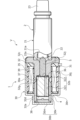
- FIG. 2 is a partial cross-sectional view showing an off state of the solenoid valve according to the first embodiment of the present invention.
- FIG. 2 is an enlarged view of the plunger in FIG. 1 .
- 5A to 5C are schematic diagrams showing a manufacturing process of a plunger.
- FIG. 4 is a partial cross-sectional view showing a solenoid valve in an on state.
- FIG. 11 is a cross-sectional view showing a plunger according to a second embodiment of the present invention.
- FIG. 11 is a cross-sectional view showing a plunger according to a third embodiment of the present invention.
- Solenoid 1 in this embodiment 1 will be described as a solenoid used in solenoid valve V. Note that solenoid 1 is not limited to solenoid valve V, and may be used in a solenoid actuator that operates any load.
- solenoid valve V is a spool-type solenoid valve used in hydraulically controlled devices such as an automatic transmission in a vehicle.
- the solenoid valve V is mounted horizontally to a mounting member such as a valve housing (not shown) and is used as a so-called oil-immersed solenoid valve, immersed in hydraulic oil in the valve housing.
- Solenoid valve V is constructed by integrally mounting a solenoid 1 and a valve 2 that adjusts the flow rate of fluid. Note that Figure 1 shows solenoid valve V in its off state with no current passing through coil 39.
- the valve 2 is composed of a sleeve 21 having openings such as an input port and an output port (not shown) on its outer periphery, which are connected to flow paths provided in a valve housing (not shown), a spool 22 having a number of lands (not shown) that are liquid-tightly accommodated in a through hole 21a of the sleeve 21, a coil spring (not shown) that biases the spool 22 towards one end in the axial direction, and a retainer 23 that holds the spring.
- This configuration is well known as a spool valve, so a detailed explanation will be omitted.
- the sleeve 21, spool 22, and retainer 23 are made of materials such as aluminum, iron, stainless steel, and resin.
- the solenoid 1 is mainly composed of a solenoid case 30, a solenoid body 31, a fixed core 32, and a plunger 4 as a movable core.
- the solenoid case 30 is made of a magnetic metal material such as iron.
- the solenoid case 30 is mainly composed of a cylindrical portion 30a and a step portion 30b.
- the cylindrical portion 30a covers the outer periphery of the solenoid molded body 31.
- the step portion 30b has a bottomed cylindrical shape that protrudes further toward one axial end than the cylindrical portion 30a and is formed with a smaller diameter than the cylindrical portion 30a.
- One axial end of the fixed iron core 32 is housed within this step portion 30b.
- the step portion 30b is composed of a disk-shaped bottom plate 30m and a cylindrical side plate 30k that is connected perpendicular to the bottom plate 30m and extends in the axial direction, and the diameter of the side plate 30k is smaller than the diameter of the cylindrical portion 30a.
- the side plate 30k and the cylindrical portion 30a are connected by an annular end plate 30n that is perpendicular to the side plate 30k and the cylindrical portion 30a.
- the central axis of the cylindrical portion 30a and the central axis of the step portion 30b are arranged to approximately coincide.
- the solenoid molded body 31 is formed into a cylindrical shape by molding the coil 39 with resin 35. Electric power is supplied to the coil 39 of the solenoid molded body 31 from the outside through an opening 30j provided below the solenoid case 30 and on the other axial end side.
- the fixed core 32 is formed in a cylindrical shape with a flange, and is mainly composed of a base 32a and a flange portion 32c.
- the base 32a extends in the axial direction and is inserted into the solenoid molding 31.
- the base 32a is formed with a stepped housing portion 32b that penetrates in the axial direction.
- the accommodation portion 32b is composed of a large diameter portion 321 and a small diameter portion 322.
- the plunger 4 is slidably accommodated in the large diameter portion 321, and the rod 5 is slidably accommodated in the small diameter portion 322.
- An annular protective member 36 for protecting the plunger 4 is attached to the annular surface portion 32g between the large diameter portion 321 and the small diameter portion 322.
- a thin-walled portion 37 is formed in the approximate center of the base 32a in the axial direction.
- the thin-walled portion 37 is formed by an annular groove that is isosceles trapezoidal in cross section and opens to the outer diameter side.
- the vicinity of the thin-walled portion 37 in the base 32a (from the thin-walled portion 37 to the annular surface portion 32g) and the annular surface portion 32g function as suction portions, and are configured to attract the plunger 4.
- the flange portion 32c extends radially from the other axial end of the base portion 32a.
- a recess 32j is provided on the end face of the other axial end of the flange portion 32c, recessed toward one axial end, and one axial end of the sleeve 21 is inserted and fixed.
- the other axial end of the cylindrical portion 30a of the solenoid case 30 is crimped to the flange portion 32c, and the fixed core 32 and the solenoid case 30 are fixed.
- the plunger 4 is formed in a cylindrical shape, and its outer circumferential surface is guided by the inner circumferential surface 32d of the base 32a of the fixed core 32, allowing it to move in the axial direction.
- a slight radial clearance is provided between the outer circumferential surface of the plunger 4 and the inner circumferential surface 32d of the fixed core 32, allowing the plunger 4 to move smoothly in the axial direction.
- the solenoid valve V when the solenoid valve V is in the off state, the plunger 4 abuts against a plate 38 sandwiched between the fixed core 32 and the bottom plate 30m of the solenoid case 30, restricting the movement of the plunger 4 toward one axial end.
- the plunger 4 is composed of a core material 41 as a magnetic material and a surface material 42 as a non-magnetic material.
- the core material 41 is made of a magnetic material such as iron and is formed into a generally cylindrical shape.
- This core material 41 has a large diameter portion 411 that is uniform in the circumferential direction at the other axial end closer to the suction part, and a small diameter portion 412 that is uniform in the circumferential direction at one axial end farther from the suction part.
- the large diameter portion 411 and the small diameter portion 412 are continuous with each other via a tapered portion 413.
- the core material 41 has a through hole 41a formed at a position offset from the radial center. This allows fluid to pass through the spaces on both axial sides of the plunger 4 through the through hole 41a when the plunger 4 moves in the axial direction.
- the surface material 42 is a coating formed on the outer surface of the core material 41 using a non-magnetic material such as a non-magnetic metal or resin.
- the surface material 42 has a first portion 421, a second portion 422, a third portion 423, and fourth portions 424, 424.
- the first portion 421 is located on the outer periphery of the large diameter portion 411.
- the second portion 422 is located on the outer periphery of the small diameter portion 412.
- the third portion 423 is located on the outer periphery of the tapered portion 413.
- the fourth portions 424, 424 are located at both axial ends of the core material 41.
- the outer diameters of the first portion 421, the second portion 422, and the third portion 423 are the same.
- the plunger 4 has the same diameter along the axial direction.
- This surface material 42' is formed with a substantially uniform thickness relative to the outer surface of the core material 41. That is, the outer peripheral surface of the first portion 421' of the surface material 42' is located on the outer diameter side of the outer peripheral surface of the third portion 423', and the outer peripheral surface of the third portion 423' is located on the outer diameter side of the outer peripheral surface of the second portion 422'.
- the first portion 421', the second portion 422', and the third portion 423' of the surface material 42' are cut to obtain a surface material 42 having the first portion 421, the second portion 422, and the third portion 423 of the same diameter.
- the thickness T1 of the first portion 421 of the surface material 42 is thinner than the thickness T2 of the second portion 422 (T1 ⁇ T2 (see particularly the enlarged portion of Figure 2)).
- the thickness T1 is 1/5 or less of the thickness T2.
- the large diameter portion 411 of the core material 41 overlaps radially with the thin wall portion 37 of the fixed core 32. In other words, the large diameter portion 411 of the core material 41 always overlaps radially with the thin wall portion 37 within the stroke range of the plunger 4.
- the fixed core 32 has a thin-walled portion 37 formed by thinning a portion of the base 32a in the circumferential direction to increase the magnetic resistance, which biases the magnetic flux flow path around the thin-walled portion 37 toward the plunger 4, thereby strengthening the magnetic force acting on the plunger 4.
- the tip of the other axial end of the rod 5 presses the end face 22a at one axial end of the spool 22, and by moving the spool 22 toward the other axial end against the biasing force of a spring (not shown), the amount of control fluid flowing from the input port (not shown) to the output port of the sleeve 21 can be changed.
- the core material 41 of the plunger 4 has a large diameter portion 411 on the other axial end side, i.e., on the annular surface portion 32g side of the fixed core 32. This allows the attracted portion of the plunger 4 to be the large diameter portion 411 and to be positioned radially closer to the thin-walled portion 37, making it possible to obtain a high thrust force in the axial direction.
- the small diameter portion 412 of the core material 41 which is located axially away from the annular surface portion 32g of the fixed core 32, is radially away from the base portion 32a and the thin-walled portion 37 of the fixed core 32, making it difficult for a radial suction force to act on it.
- the second portion 422 of the surface material 42 has the same diameter as the first portion 421, and the first portion 421 and the second portion 422 are guided by the inner peripheral surface 32d of the fixed core 32, so that the axial drive of the plunger 4 can be stabilized.
- first portion 421, the second portion 422, and the third portion 423 of the surface material 42 have the same diameter and are continuous in the axial direction. This ensures that the portion guided by the inner peripheral surface 32d of the fixed core 32 is large in the axial direction, further stabilizing the axial drive of the plunger 4.
- the large diameter portion 411 of the core material 41 always overlaps the thin wall portion 37 in the radial direction within the stroke range of the plunger 4. This allows the large diameter portion 411 to be positioned closer to the thin wall portion 37 in the radial direction, so the axial thrust of the plunger 4 is high.
- the surface material 42 is a plated layer made of a non-magnetic material, so it can be made thin, ensuring that suction force acts on the large diameter portion 411, and also providing excellent rust prevention performance.
- the coefficient of dynamic friction during the stroke of the plunger 4 is the same in the axial direction, making the stroke of the plunger 4 stable.
- first portion 421', the second portion 422', and the third portion 423' of the surface material 42' are cut to form the first portion 421, the second portion 422, and the third portion 423 of the same diameter, so that the first portion 421, the second portion 422, and the third portion 423 are in the same cutting state, and the dynamic friction coefficient during the stroke of the plunger 4 can be made approximately the same in the axial direction, stabilizing the stroke of the plunger 4.
- the large diameter portion 411 and the small diameter portion 412 are smoothly connected by the tapered portion 413, so that the magnetic flux can stably pass through the tapered portion 413 in the axial direction. Therefore, the axial drive of the plunger 4 is more stable than when the large diameter portion 411 and the small diameter portion 412 are connected in a curved manner.
- the surface material 42 can be easily formed uniformly, and plating is easy.
- the core material 41 of the plunger 4 also has a through hole 41a that connects the spaces on both sides in the axial direction. Because the through hole 41a is thus provided inside the core material 41, the suction force acts on the core material 41 without bias in the circumferential direction, and the axial drive of the plunger 4 is stable.
- first portion 421', the second portion 422', and the third portion 423' of the surface material 42' are cut to have the same diameter, but the first portion 421' and the third portion 423' may be cut to have the same diameter as the second portion 422'.
- the core material 241 of the plunger 24 in this embodiment 2 has a large diameter portion 241a, a tapered portion 241c, and a small diameter portion 241b that are uniformly shaped in the circumferential direction from the other axial end side to the one axial end side.
- the surface material 242 is formed on the outer surface of the core material 241 by plating with a non-magnetic material.
- the first portion 242a of the surface material 242 has the same diameter as the fifth portion 242e located on the outer periphery of the end portion of the surface material 242 on one axial end side of the plunger 24.
- the second portion 242b and the third portion 242c of the surface material 242 have smaller diameters than the first portion 242a and the fifth portion 242e.
- the first portion 242a of the surface material 242 is guided to the inner peripheral surface 32d (see FIG. 1) of the fixed core 32 at the other axial end, and the fifth portion 242e of the surface material 242 is guided to the inner peripheral surface 32d (see FIG. 1) of the fixed core 32 at one axial end, so that the axial drive is stable.
- the fifth portion 242e is provided on the surface material 242, but this is not limited to the above.
- the small diameter portion and the portion located on the outer periphery of the tapered portion in the surface material may be cut to have a smaller diameter than the large diameter portion and the portion located on the outer periphery of one axial end, thereby forming equal diameter portions at both axial ends of the surface material.
- the same diameter portion of the non-magnetic material in the small diameter portion as the non-magnetic material in the large diameter portion is not limited to being provided at one axial end, and the axial position can be freely changed.
- the axial length of the same diameter portion can also be freely changed.
- the same diameter portion is not limited to being annular.
- the core material 341 of the plunger 34 in this embodiment 3 has the same shape as the core material 41 in the embodiment 1.
- the surface material 342 is formed with a uniform thickness on the outer surface of the core material 341 by plating with a non-magnetic material.
- a ring member 343 made of a non-magnetic material is fitted to the outer peripheral surface of one axial end of the surface material 342. This ring member 343 and the first portion 342a of the surface material 342 have the same diameter.
- the first portion 342a of the surface material 342 is guided to the inner peripheral surface 32d (see FIG. 1) of the fixed core 32 at the other axial end, and the ring member 343 is guided to the inner peripheral surface 32d (see FIG. 1) of the fixed core 32 at one axial end, so that the axial drive is stable.
- a form in which surface material 342 is formed on the outer surface of core material 341 by plating with a non-magnetic material is exemplified, but for example, ring members of the same outer diameter but different thicknesses may be attached to the large diameter portion and small diameter portion of the core material without plating the outer surface of the core material.
- the non-magnetic material is not limited to being annular.
- the large diameter portion of the magnetic material is provided closer to the attraction portion of the fixed iron core than the small diameter portion, but the small diameter portion of the magnetic material may be provided closer to the attraction portion of the fixed iron core than the large diameter portion.
- the outer peripheral surface of the core material is uniform in the circumferential direction, but it does not have to be uniform in the circumferential direction.
- the large diameter portion of the magnetic material overlaps radially with the thin wall portion of the fixed core within the stroke range of the movable core, but the large diameter portion may be axially separated from the thin wall portion within the stroke range of the movable core.
- the large diameter portion and the small diameter portion of the magnetic material are connected by a tapered portion, but the large diameter portion and the small diameter portion may be stepped (i.e., a surface extending in the radial direction is interposed between the large diameter portion and the small diameter portion).
- the tapered portion has a straight cross section, but it may have a curved cross section.
- a through hole that penetrates the magnetic material in the axial direction is formed, but a groove extending in the axial direction may be provided on the outer circumferential surface of the movable iron core. Furthermore, if the spaces on both sides of the movable iron core in the axial direction are connected to the external space, the through hole configuration may be omitted.
- the suction portion of the fixed iron core is provided on the outer diameter side and the other axial end side of the movable iron core, but it is sufficient that the suction portion is provided on at least one of them.
Landscapes
- Engineering & Computer Science (AREA)
- Physics & Mathematics (AREA)
- Electromagnetism (AREA)
- General Engineering & Computer Science (AREA)
- Power Engineering (AREA)
- Mechanical Engineering (AREA)
- Magnetically Actuated Valves (AREA)
Priority Applications (1)
| Application Number | Priority Date | Filing Date | Title |
|---|---|---|---|
| JP2025512540A JPWO2024210067A1 (https=) | 2023-04-03 | 2024-03-29 |
Applications Claiming Priority (2)
| Application Number | Priority Date | Filing Date | Title |
|---|---|---|---|
| JP2023-060405 | 2023-04-03 | ||
| JP2023060405 | 2023-04-03 |
Publications (1)
| Publication Number | Publication Date |
|---|---|
| WO2024210067A1 true WO2024210067A1 (ja) | 2024-10-10 |
Family
ID=92971769
Family Applications (1)
| Application Number | Title | Priority Date | Filing Date |
|---|---|---|---|
| PCT/JP2024/013214 Ceased WO2024210067A1 (ja) | 2023-04-03 | 2024-03-29 | ソレノイド |
Country Status (2)
| Country | Link |
|---|---|
| JP (1) | JPWO2024210067A1 (https=) |
| WO (1) | WO2024210067A1 (https=) |
Citations (3)
| Publication number | Priority date | Publication date | Assignee | Title |
|---|---|---|---|---|
| JPH01135706U (https=) * | 1988-03-09 | 1989-09-18 | ||
| JP2008256090A (ja) * | 2007-04-04 | 2008-10-23 | Kuroda Pneumatics Ltd | 電磁ソレノイド |
| JP2011108781A (ja) * | 2009-11-16 | 2011-06-02 | Denso Corp | リニアソレノイド |
-
2024
- 2024-03-29 JP JP2025512540A patent/JPWO2024210067A1/ja active Pending
- 2024-03-29 WO PCT/JP2024/013214 patent/WO2024210067A1/ja not_active Ceased
Patent Citations (3)
| Publication number | Priority date | Publication date | Assignee | Title |
|---|---|---|---|---|
| JPH01135706U (https=) * | 1988-03-09 | 1989-09-18 | ||
| JP2008256090A (ja) * | 2007-04-04 | 2008-10-23 | Kuroda Pneumatics Ltd | 電磁ソレノイド |
| JP2011108781A (ja) * | 2009-11-16 | 2011-06-02 | Denso Corp | リニアソレノイド |
Also Published As
| Publication number | Publication date |
|---|---|
| JPWO2024210067A1 (https=) | 2024-10-10 |
Similar Documents
| Publication | Publication Date | Title |
|---|---|---|
| JP5125441B2 (ja) | リニアソレノイド装置および電磁弁 | |
| JP5931742B2 (ja) | ソレノイドバルブ | |
| KR20010092280A (ko) | 전자기 구동장치, 전자기 구동장치를 구비한 유체제어밸브 및 전자기 구동장치 제조 방법 | |
| JP7463104B2 (ja) | ソレノイドバルブ | |
| US20090121817A1 (en) | Linear solenoid | |
| KR20210064375A (ko) | 솔레노이드 | |
| EP1848013B1 (en) | Proportional solenoid and flow control valve employing it | |
| JP3975941B2 (ja) | 電磁駆動装置 | |
| US12046418B2 (en) | Solenoid | |
| WO2020226101A1 (ja) | ソレノイドバルブ | |
| JP7467607B2 (ja) | ソレノイドバルブ | |
| JP7007218B2 (ja) | ソレノイドバルブ | |
| WO2024210067A1 (ja) | ソレノイド | |
| EP3967911B1 (en) | Solenoid valve | |
| US11908620B2 (en) | Solenoid | |
| JP7650608B2 (ja) | ソレノイドバルブ | |
| EP4296552A1 (en) | Solenoid valve | |
| US11948737B2 (en) | Solenoid | |
| JP7136068B2 (ja) | ソレノイドバルブ | |
| JPWO2019017271A1 (ja) | ソレノイドバルブ | |
| JP2024159215A (ja) | ソレノイドおよびその組立方法 | |
| JP7725416B2 (ja) | 電磁弁 | |
| JP7338528B2 (ja) | ソレノイドバルブ | |
| KR102868228B1 (ko) | 전자 밸브 | |
| JP4807306B2 (ja) | 電磁弁 |
Legal Events
| Date | Code | Title | Description |
|---|---|---|---|
| 121 | Ep: the epo has been informed by wipo that ep was designated in this application |
Ref document number: 24784853 Country of ref document: EP Kind code of ref document: A1 |
|
| ENP | Entry into the national phase |
Ref document number: 2025512540 Country of ref document: JP Kind code of ref document: A |
|
| WWE | Wipo information: entry into national phase |
Ref document number: 2025512540 Country of ref document: JP |
|
| NENP | Non-entry into the national phase |
Ref country code: DE |
|
| 122 | Ep: pct application non-entry in european phase |
Ref document number: 24784853 Country of ref document: EP Kind code of ref document: A1 |