WO2024209822A1 - 情報処理装置、プレス機械システム及びデータ生成方法 - Google Patents
情報処理装置、プレス機械システム及びデータ生成方法 Download PDFInfo
- Publication number
- WO2024209822A1 WO2024209822A1 PCT/JP2024/006497 JP2024006497W WO2024209822A1 WO 2024209822 A1 WO2024209822 A1 WO 2024209822A1 JP 2024006497 W JP2024006497 W JP 2024006497W WO 2024209822 A1 WO2024209822 A1 WO 2024209822A1
- Authority
- WO
- WIPO (PCT)
- Prior art keywords
- display
- shape model
- unit
- workpiece
- information processing
- Prior art date
- Legal status (The legal status is an assumption and is not a legal conclusion. Google has not performed a legal analysis and makes no representation as to the accuracy of the status listed.)
- Ceased
Links
Images




Classifications
-
- B—PERFORMING OPERATIONS; TRANSPORTING
- B30—PRESSES
- B30B—PRESSES IN GENERAL
- B30B15/00—Details of, or accessories for, presses; Auxiliary measures in connection with pressing
-
- G—PHYSICS
- G05—CONTROLLING; REGULATING
- G05B—CONTROL OR REGULATING SYSTEMS IN GENERAL; FUNCTIONAL ELEMENTS OF SUCH SYSTEMS; MONITORING OR TESTING ARRANGEMENTS FOR SUCH SYSTEMS OR ELEMENTS
- G05B19/00—Program-control systems
- G05B19/02—Program-control systems electric
- G05B19/18—Numerical control [NC], i.e. automatically operating machines, in particular machine tools, e.g. in a manufacturing environment, so as to execute positioning, movement or co-ordinated operations by means of program data in numerical form
- G05B19/19—Numerical control [NC], i.e. automatically operating machines, in particular machine tools, e.g. in a manufacturing environment, so as to execute positioning, movement or co-ordinated operations by means of program data in numerical form characterised by positioning or contouring control systems, e.g. to control position from one programmed point to another or to control movement along a programmed continuous path
Definitions
- the present invention relates to an information processing device, a press machine system, and a data generation method.
- a press machine clamps a workpiece between an upper die and a lower die, and performs press processing such as forming on the workpiece.
- One type of press machine known is a press brake (bending machine) that performs bending processing on plate-shaped workpieces. With this press brake, an operator places the workpiece in a specified position and drives the upper or lower die to clamp the workpiece between the upper and lower dies, thereby performing bending processing. At each stage of bending the workpiece, the operator checks the direction of the workpiece to be pressed against the backgauge using work instructions or design drawings related to the workpiece.
- the display attributes of the workpiece displayed on the display unit are the same for all processes. For this reason, for example, even if the worker checks the workpiece displayed on the display unit in a certain process, it may be difficult to see and may not be able to check the parts that require attention when placing the workpiece. As a result, depending on the process, the worker may not notice the parts that require attention even when looking at the image displayed on the display unit, and may end up placing the workpiece on the press machine in the wrong orientation. This requires the worker to carefully observe the image displayed on the display unit and find the parts that require attention. However, this work takes time and places a heavy burden on the worker.
- the object of the present invention is to provide an information processing device, a press machine system, and a data generation method that contribute to reducing the burden on workers.
- the information processing device is an information processing device that creates a shape model for displaying an image to assist an operator in his work on a display unit of a press machine that processes a workpiece, and includes a data generation unit that generates the shape model when processing the workpiece, an input unit that accepts input of display attributes of the shape model, and a setting unit that sets the display attributes of the shape model when displayed on the display unit to the display attributes accepted by the input unit.
- a press machine system includes the above-mentioned information processing device and a press machine that processes a workpiece by clamping the workpiece between an upper die and a lower die, and the press machine includes a main body that holds either the upper die or the lower die, a display that is provided on the main body or separately from the main body, and a control device that displays a shape model on the display with the display attributes set in the setting unit.
- the data generation method is a data generation method for an information processing device that creates a shape model for displaying an image to assist an operator in the work on a display unit of a press machine that processes a workpiece, and includes generating a shape model for use when processing a workpiece, accepting input of display attributes of the shape model, and setting the display attributes of the shape model for use when displaying the shape model on the display unit to the accepted display attributes.
- the information processing device or data generation method allows the display attributes of the shape model to be set so that it is easy to check the parts that require attention when performing bending. As a result, the worker can passively know the parts that require attention, which contributes to reducing the burden on the worker.
- the setting unit may be capable of setting different display attributes for each process.
- the worker can carry out bending work for each process while checking an image corresponding to the process.
- the display attribute may be at least one of the display angle, the display magnification, and the transparency.
- FIG. 1 is a diagram illustrating an example of a press machine system according to an embodiment of the present invention.
- FIG. 1 is a side view illustrating an example of a press machine according to an embodiment of the present invention.
- FIG. 3 is a front view of the press machine shown in FIG. 2 .
- 1A and 1B are diagrams illustrating an example of an image projected by the projection device according to the present embodiment.
- FIG. 2 is a diagram illustrating an example of a functional block of a press machine according to the present embodiment.
- FIG. 2 is a diagram illustrating an example of a hardware configuration of an information processing device according to the present embodiment.
- FIG. 2 is a functional block diagram of a processor according to the embodiment.
- FIG. 4 is a diagram showing an example of process support data according to the embodiment;
- FIG. 4 is a diagram showing an example of process support data according to the embodiment; FIG.
- FIG. 13 is a diagram showing an example of a shape model before a display angle according to the present embodiment is changed.
- FIG. 2 is a functional block diagram of a processor according to the embodiment.
- FIG. 13 is a diagram showing an example of a shape model before a display angle according to the present embodiment is changed.
- 1A and 1B are diagrams illustrating a workpiece arranged in a correct orientation according to the present embodiment.
- 1A and 1B are diagrams illustrating a workpiece arranged in a correct orientation according to the present embodiment.
- 13 is a diagram showing an example of a shape model after a display angle according to the embodiment is changed;
- FIG. 1 is a diagram showing an example of a press machine system RS according to this embodiment.
- the press machine system RS includes a press machine 100, a higher-level device 200, and an information processing device 300.
- FIG. 2 is a side view showing an example of a press machine 100 according to this embodiment.
- FIG. 3 is a front view of the press machine 100 shown in FIG. 2.
- the press machine 100 is, for example, a press brake capable of performing bending processing on a workpiece W.
- the press machine 100 is a press brake, but is not limited to a press brake.
- the press machine 100 may be a machine (e.g., a turret punch press) equipped with a tool (e.g., a die) capable of performing punching (punching) or forming processing on the workpiece W.
- the press machine 100 comprises a main body 2, a projection device 3, a control device 4, a display device 23, and an operation unit 24.
- the main body 2 has a work space for an operator OP on the front side.
- the operator OP can place a workpiece W in a predetermined position from the front side of the main body 2 and perform bending processing on the workpiece W by sandwiching the workpiece W between an upper die 13 and a lower die 6 described below.
- the main body 2 comprises, for example, a main body frame 5, a table 7, side frames 8 and 9, a cover member 10, and a ram 11.
- the main body frame 5 forms the outer shell of the press machine 100.
- the lower die 6 is a fixed (lower) die supported on the upper surface of the table 7, and is formed along the left-right direction (X direction).
- the upper surface of the lower die 6 has a V-shaped recess 6a for bending the workpiece W.
- the recess 6a is formed along the left-right direction.
- the table 7 is attached to the front side (front surface) of the main body frame 5, and fixes the lower die 6.
- the table 7 is also provided with a back gauge 7a for butting the workpiece W in the +Y direction to position it.
- the back gauge 7a may be provided independently of the main body frame 5.
- the side frames 8, 9 are attached to the upper left and right sides of the main frame 5.
- the side frames 8, 9 are arranged to cover the upper left and right sides of the ram 11.
- the side frames 8, 9 each house a drive unit 14.
- the drive unit 14 is supported on the main body 2 by a support frame (not shown) or the like.
- the drive unit 14 moves (raises and lowers) the ram 11 in the Z direction.
- the drive unit 14 may be, for example, a mechanism that raises and lowers the ram 11 by rotating a ball screw or a nut using an electric motor or the like, or a mechanism that raises and lowers the ram 11 using a hydraulic cylinder device or a pneumatic cylinder device.
- the cover member 10 is disposed between the side frames 8, 9 in the left-right direction (X direction).
- the cover member 10 is disposed on the upper part of the main frame 5, above and in front of the ram 11.
- the cover member 10 has a portion that protrudes forward (-Y direction) relative to the ram 11.
- the cover member 10 houses the projection device 3, which will be described later, in this protruding portion.
- the ram 11 is supported by a guide portion (not shown) provided on the main frame 5 so that it can be raised and lowered on the main body portion 2.
- the ram 11 is a plate-shaped member made of, for example, metal.
- the ram 11 is connected to a part of the drive device 14 and is arranged in a state where it is suspended by the drive device 14.
- the ram 11 is raised and lowered by driving the drive device 14, and moves toward or away from the lower mold 6 on the table 7.
- a number of upper die holders 12 are attached below the ram 11.
- the multiple upper die holders 12 are arranged in the left-right direction (X direction).
- the spacing between the multiple upper die holders 12 can be set as desired.
- the upper die holders 12 may also be configured to be movable in the left-right direction relative to the ram 11, for example, so that the spacing between the upper die holders 12 can be changed.
- the upper die holders 12 are detachably mounted on the ram 11.
- Each of the multiple upper die holders 12 is capable of holding an upper die 13. For example, when bending the workpiece W, the multiple upper die holders 12 hold upper dies 13 corresponding to each step of the bending process.
- the upper die 13 When held by the upper die holder 12, the upper die 13 is arranged with its lower end facing above the recess 6a of the lower die 6 and aligned in the left-right direction.
- the lower end of the upper die 13 has a tip that enters the recess 6a of the lower die 6.
- the upper die 13 rises and falls together with the ram 11 and the upper die holder 12.
- the upper die 13 moves toward the lower die 6 as the ram 11 moves, and the workpiece W is sandwiched between the upper die 13 and the lower die 6, and bending is performed on the workpiece W until the upper die 13 reaches its lowest point.
- the projection device 3 is provided on the main body 2 and projects an image G to assist the worker OP in the bending work onto a projection area PA including at least a part of the ram 11.
- FIG. 4 is a diagram showing an example of an image G projected by the projection device 3.
- the image G may be a still image or a moving image.
- the worker OP places the work W in a predetermined position by butting the work W against the back gauge 7a, and performs bending processing on the work W by clamping the work W between the upper die 13 and the lower die 6.
- the orientation in which the workpiece W is placed may differ in each step.
- the orientation in which the workpiece is butted against the back gauge 7a may differ in each step.
- the worker OP needs to clamp the workpiece W between the upper die 13 and the lower die 6 while changing the orientation of the workpiece W when it is butted against the back gauge 7a (hereinafter, sometimes simply referred to as the "orientation of the workpiece W").
- the worker OP needs to perform the bending work while determining the orientation of the workpiece W when it is butted against the back gauge 7a at each step.
- the projection device 3 displays an image G showing the orientation of the workpiece W determined in each step for each step.
- the orientation of the workpiece W refers to the direction of the workpiece W butted against the back gauge 7a and/or the orientation of the front and back of the workpiece W.
- the image G has a shape model MD for machining the workpiece W.
- This shape model MD is a two-dimensional or three-dimensional model.
- the shape model MD includes, for example, a shape model MS of the workpiece W in a state where it is pressed against the backgauge 7a in a preset orientation.
- the shape model MD may also further include two-dimensional or three-dimensional shape models of the backgauge 7a, the upper die 13, and the lower die 6, for example, as illustrated in FIG. 4. Note that data for displaying the image G on the display unit is created in advance by the information processing device 300.
- FIG. 5 is a diagram showing an example of functional blocks of the press machine 100.
- the control device 4 includes a control unit 20 and a memory unit 21.
- the control unit 20 is, for example, a hardware processor such as a CPU (Central Processing Unit).
- the control unit 20 includes, for example, a main body control unit 31 and a display control unit 32.
- the control unit 20 reads out the processing program PR and the like stored in the memory unit 21 and controls the operation of the drive unit 14 and the projection device 3.
- the memory unit 21 may be provided in the main body 2, or may be provided outside the main body 2 and connected to the control device 4 by wire or wirelessly.
- the memory unit 21 is, for example, a large-capacity storage device such as a hard disk, a non-volatile memory such as a USB memory or flash memory, or a recording medium such as a CD.
- the memory unit 21 stores the processing program PR.
- the processing program PR is a program (processing data) that defines the operation of the main body unit 2 for each process.
- the processing program PR defines the order of processes in bending, information about the upper die 13 used in each process (e.g., type, ID, position), and the movement conditions of the ram 11 in each process (e.g., start position, speed, end position).
- the main body control unit 31 controls the drive unit 14 according to the command of the operator OP and the processing program. For example, the main body control unit 31 controls the drive unit 14 to start operating upon receiving a signal from an operation pedal or operation lever (not shown) operated by the operator OP.
- the main body control unit 31 controls the display device 23 to display various information such as the operating status and operating conditions of the main body unit 2 and the processing conditions of the workpiece W.
- the operator OP can input information such as the settings of the main body unit 2, the material of the workpiece W, and the processing conditions to the control device 4 using the operation unit 24.
- the control device 4 is connected to the upper device 200 by wire or wirelessly.
- the upper device 200 supplies the control device 4 with bending CAM data BD including data for displaying the image G.
- the bending CAM data BD may further include position information of the backgauge 7a for each process.
- the bending CAM data BD supplied from the upper device 200 is stored in the memory unit 21.
- the display device 23 and the operation unit 24 are provided on the front side of the main body 2 as shown in FIG. 2, and are arranged at a height that allows the operator OP to view and operate them.
- the display device 23 is a direct-view type, for example, a liquid crystal display device.
- the display device 23 is capable of displaying the image G described above.
- the display unit of the press machine 100 in this embodiment may be provided in the main body 2 or may be provided separately from the main body 2.
- the installation position of the display unit of the press machine 100 is not particularly limited, but for example, the display unit of the press machine 100 may be the projection area PA of the ram 11, or may be the display device 23 provided separately from the main body 2, or may be both.
- the operation unit 24 is a keyboard, a mouse, or a touch panel provided on the display device 23.
- the operation unit 24 is provided integrally with the display device 23.
- the touch panel provided on the display device 23 may also be equipped with a keyboard or the like.
- the display device 23 may be disposed on the ram 11.
- the display control unit 32 controls the operation of the projection device 3. For example, the display control unit 32 controls the projection device 3 to project an image G for supporting processing at each process of bending the workpiece W based on the bending CAM data BD.
- the display control unit 32 also controls the operation of the display device 23.
- the display control unit 32 may cause the display device 23 to display an image G at each process of bending the workpiece W based on the bending CAM data BD.
- the information processing device 300 creates bending CAM data BD before bending processing by the press machine 100.
- the information processing device 300 is, for example, a computer having a function of CAM (Computer-aided manufacturing), which is software for creating bending CAM data BD.
- the information processing device 300 is connected to a communication network NW, and transmits the bending CAM data BD to the upper device 200 via the communication network NW.
- the upper device 200 then transmits the bending CAM data BD to the press machine 100.
- the information processing device 300 may transmit the bending CAM data BD to the press machine 100 via the communication network NW without going through the upper device 200.
- the information processing device 300 is disposed in a location different from the location where the press machine 100 is installed.
- the communication network NW may be wired, wireless, or both.
- FIG. 6 is a diagram showing an example of the hardware configuration of an information processing device 300 according to this embodiment.
- the information processing device 300 includes a storage device 40, a communication device 41, an input unit 42, and a processor 43.
- the storage device 40 may not be a part of the information processing device 300, but may be an external storage device.
- the information processing device 300 is connected to the storage device 40 by wire or wirelessly, and transmits and receives information to and from the storage device 40.
- the storage device 40 stores, for example, a program (CAM software) for executing the process of creating bending CAM data BD, and data processed by this program.
- the storage device 40 includes, for example, a non-volatile memory such as a ROM (Read Only Memory), a HDD (Hard Disk Drive), and an SSD (Solid State Drive).
- the above-mentioned programs may be provided by a computer-readable storage medium, or may be provided from an external device via a wired or wireless communication network.
- the provided programs are stored in the storage device 40 and executed by the processor 43.
- the storage device 40 also stores process information such as information (for example, CAD data) regarding the shape of the workpiece W to be bent in each process, the contents of the processes in the bending process, and information regarding the order of the processes.
- the communication device 41 is a communication interface for communicating with external devices.
- the communication device 41 communicates with the higher-level device 200 via the communication network NW.
- the input unit 42 accepts input from the user. For example, when the input unit 42 accepts input from the user via the operation unit 44, it transmits information corresponding to the accepted input to the processor 43 or the storage device 40.
- the operation unit 44 includes a touch panel, a touch pad, a pointing device such as a mouse, a button, a switch, a motion-sensitive controller, a keyboard, a mouse, a gesture input device, or a voice input device (e.g., a microphone).
- the input unit 42 is connected to the operation unit 44, and accepts input of information corresponding to the operation of the operation unit 44 by the user.
- the processor 43 executes the process of creating the bending CAM data BD.
- the processor 43 is operable to execute a program stored in the storage device 40 and to execute operations described by the program, i.e., processes related to the creation of the bending CAM data BD.
- the processor 43 includes at least one of a CPU (Central Processing Unit), an MPU (Micro Processing Unit), and a GPU (Graphics Processing Unit).
- the above program may be provided by a computer-readable storage medium.
- the program is read from the computer-readable storage medium, installed in the storage device 40, and executed by the processor 43.
- the above program may be downloaded from an external device via the communication network NW.
- Examples of computer-readable storage media may include electronic storage media, magnetic storage media, optical storage media, electromagnetic storage media, semiconductor storage media, etc. More specific examples of computer-readable storage media may include diskettes, hard disks, random access memories (RAMs), read-only memories (ROMs), erasable programmable read-only memories (EPROMs or flash memories), electrically erasable programmable read-only memories (EEPROMs), static random access memories (SRAMs), compact disc read-only memories (CD-ROMs), digital versatile discs (DVDs), Blu-ray (RTM) discs, memory sticks, integrated circuit cards, etc.
- RAMs random access memories
- ROMs read-only memories
- EPROMs or flash memories erasable programmable read-only memories
- EEPROMs electrically erasable programmable read-only memories
- SRAMs static random access memories
- CD-ROMs compact disc read-only memories
- DVDs digital versatile discs
- RTM Blu-ray
- the information processing device 300 is connected to a display device 400.
- the display device 400 displays various information.
- the display device 400 is a monitor for a personal computer.
- the present invention is not limited to this, and the display device 400 may be a display device (display) of a portable device such as a mobile phone, a smartphone, or a tablet terminal.
- the information processing device 300 may be configured to include the display device 400.
- FIG. 7 is a functional block diagram of the processor 43 according to this embodiment.
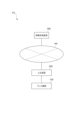
- the processor 43 includes a data generation unit 50, a display control unit 51, and a setting unit 52.
- the data generation unit 50, the display control unit 51, and the setting unit 52 are realized by the processor 43 executing the above-mentioned program stored in the storage device 40.
- the data generation unit 50 generates a three-dimensional shape model MD for processing the workpiece W based on information including the CAD data of the workpiece W.
- the data generation unit 50 generates a shape model MD for each process based on information including the CAD data of the workpiece W for each process.
- the shape model MD has, for example, a two-dimensional or three-dimensional shape model MS of the workpiece W when bending is performed in the process corresponding to the shape model MD.
- the display control unit 51 causes the display device 400 to display various information.
- the display control unit 51 can cause the display device 400 to display the shape model MD generated by the data generation unit 50 for each process. Furthermore, when displaying the shape model MD on the display device 400, the display control unit 51 can freely change the display attributes of the shape model MD. For example, as an example of a display attribute, the display control unit 51 can change the display angle of the shape model MD displayed on the display device 400. For example, when the display control unit 51 receives a display attribute of the shape model MD from the input unit 42, it changes the display angle of the shape model MD displayed on the display device 400 to the display attribute received by the input unit 42.
- the display attributes of the shape model MD when the display attributes of the shape model MD are received by the input unit 42, this includes both or either of the following: when the display attributes of the shape model MD displayed on the display device 400 are changed by operating a pointing device, and when the display attributes of the shape model MD are acquired by operating a keyboard, voice input device, or the like.
- the display attributes are, for example, at least one of the display angle, display magnification, and transmittance of the shape model MD. Note that the display angle of the shape model MD is synonymous with the viewpoint of the shape model MD.
- the setting unit 52 sets the display attributes of the shape model MD when the shape model is displayed on the display unit of the press machine 100 to the display attributes received by the input unit 42. For example, when the bending work includes multiple processes, the setting unit 52 can set the display attributes of the shape model MD when the shape model is displayed on the display unit of the press machine 100 for each process. For example, the setting unit 52 sets the display attributes of the shape model MD for each process by associating the shape model MD in each process with the display attributes of the shape model MD and storing them in the storage unit 21.
- the data in which the shape model MD and the display attributes of the shape model MD are associated with each other may be referred to as "process support data".
- the setting unit 52 stores the process support data for each process in the storage unit 21.
- the setting unit 52 may store the display angle in the storage unit 21 as vector information.
- the press machine 100 displays the display angle of the shape model MD on the display unit of the press machine 100 according to the vector information.
- FIG. 8 is a diagram showing an example of process support data.
- the process support data shown in FIG. 8 is data for a bending process having three processes (first process, second process, and third process).
- a shape model MD1 is associated with a display attribute IP1 of the shape model MD1 as process support data for the first process.
- a shape model MD2 is associated with a display attribute IP2 of the shape model MD2 as process support data for the second process.
- a shape model MD3 is associated with a display attribute IP3 of the shape model MD3 as process support data for the third process.
- the display attributes IP1, IP2, and IP3 two or more of them may have different values. In other words, the display attributes IP1, IP2, and IP3 do not need to all be set to the same value, and two or more of them may be set to different values.
- the setting unit 52 can set the display attributes of the shape model MD. Therefore, the setting unit 52 can set a display attribute different from the display attribute of the shape model MD corresponding to a first process among the multiple processes as the display attribute of the shape model MD corresponding to a second process different from the first process.
- setting the display attribute includes not only setting a new display attribute but also changing the setting of the display attribute. For example, when the display attribute of the shape model MD corresponding to the second process has already been set and the display attribute of the shape model MD in the second process is newly input by the input unit 42, the setting unit 52 changes the setting of the display attribute of the process support data in the second process to the newly input display attribute.
- the setter SL operates the operation unit 44 to select a shape model MD of any process from the shape models MD of each process generated by the data generation unit 50, thereby causing a part or all of the selected shape model MD to be displayed on the display device 400.
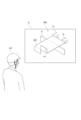
- FIG. 9 is a diagram showing an example of the shape model MD before the display angle is changed.
- the shape model MD displayed on the display device 400 has a shape model of the lower mold 6, a shape model of the backgauge 7a, and a shape model MS of the workpiece W that is abutted against the backgauge 7a in a preset orientation.
- the part that the worker OP should pay attention to is a hole HI formed in the workpiece W.
- the setter SL changes the display angle of the shape model MS displayed on the display device 400 to a display angle at which the hole HI can be seen, as shown in the example of FIG. 10.
- FIG. 10 is a diagram showing an example of the display angle of the shape model MD after changing the display angle shown in FIG. 9.
- the setter SL operates the operation unit 44 (e.g., dragging) to rotate or move the shape model MD shown in FIG. 9, thereby changing the display of the display device 400 from the display angle shown in FIG. 9 to the display angle shown in FIG. 10. That is, when the setter SL operates the operation unit 44 and the input unit 42 receives the information of the display angle shown in FIG. 10, the display control unit 51 changes the display of the display device 400 from the display angle shown in FIG. 9 to the display angle shown in FIG. 10. Then, when the setter SL displays an image of the shape model MD at the display angle shown in FIG.
- the operation unit 44 e.g., dragging
- the setter SL performs a predetermined operation to save the display angle of the shape model MD after the change, that is, the display angle shown in FIG. 10.
- the predetermined operation is an operation for saving the display angle after the change, for example, an operation of pressing a save button icon displayed on the display device 400.
- the setting unit 52 stores the display angle of the shape model MD displayed on the display device 400, i.e., the display angle shown in FIG. 10 received by the input unit 42, in the storage unit 21 as a display attribute.
- the data of the shape model MD of the selected process and the display angle of the shape model MD displayed on the display device 400 are associated with each other and stored in the storage unit 21 as process support data.
- the parameter set by the setting person SL as the display attribute is not limited to the display angle, and may be the display magnification or the transparency of the work.
- the setter SL does not have to set the shape models MD for all processes. For example, when the data generation unit 50 creates a shape model MD for each process, the setting unit 52 sets the first display attribute as the display attribute of the shape model MD for each process. In other words, the setting unit 52 sets the first display attribute as the default display attribute of the shape models MD for all processes. Then, when the setter SL wants to change the display attribute of the shape model MD for a specific process among multiple processes, he or she operates the operation unit 44 to change the display attribute of the shape model MD for the specific process from the first display attribute to the second display attribute.
- the setter SL operates the operation unit 44 to input a second display attribute different from the first display attribute to the information processing device 300. Then, the setter SL performs the above-mentioned predetermined operation to save the setting of the second display attribute.
- the setting unit 52 changes the display attribute of the shape model MD for the specific process stored in the memory unit 21 from the first display attribute to the second display attribute.
- the second display attribute may be a display angle at which the part to be noted can be confirmed.
- the second display attribute may also be the transparency of the shape model MD.
- the setter SL may increase the transparency of that part to set it to a transparency that allows the part to be noted to be seen through.
- the setter SL increases the transparency of a part of PK to set it to a transparency that allows the hole HI, which is the part to be noted, to be seen through.
- the second display attribute may also be the display magnification.
- the person SL may set the display magnification of the shape model MD in a particular process to be high, with the part requiring attention (e.g., hole HI) as the center position so that the part requiring attention is clearly visible.
- the display magnification is set as the display attribute, the information on the center position may also be set at the same time.
- the bending CAM data BD including the process support data for each process stored in the storage device 40, is sent to the press machine 100.
- the information processing device 300 may transmit the bending CAM data BD to the upper device 200.
- the setter SL operates the operation unit 44 to cause the information processing device 300 to transmit the bending CAM data BD, including the process support data for each process stored in the storage device 40, to the upper device 200.
- the upper device 200 receives the bending CAM data BD from the information processing device 300 and transmits the received bending CAM data BD to the control device 4 of the press machine 100.
- the information processing device 300 may directly transmit the bending CAM data BD to the control device 4 of the press machine 100.
- the bending CAM data BD is not limited to being transmitted from the information processing device 300 or the upper device 200.
- the worker OP may connect a storage medium such as a USB memory that stores the bending CAM data BD to the control device 4, and import the bending CAM data BD into the control device 4.
- the power is turned on to the press machine 100, and the press machine 100 performs start-up operations such as returning to the origin and goes into a ready state (standby state).
- the worker OP operates the operation unit 24 to input to the control device 4 that the work will begin.
- the control device 4 detects the input to start the work, it requests the bending CAM data BD from the higher-level device 200.
- the higher-level device 200 transmits the bending CAM data BD to the control device 4.
- the control device 4 takes in the bending CAM data BD transmitted from the higher-level device 200 or stored in a storage medium, and stores it in the memory unit 21.
- the control device 4 controls the projection of an image G for each process onto the projection area PA based on the process support data for each process included in the bending CAM data BD. For example, if the bending work performed by the worker OP has two processes, a first process and a second process, the control device 4 first reads the process support data corresponding to the first process, and projects the shape model MD included in that process support data onto the projection area PA with the display attribute included in the process support data. For example, if a display angle is set as the display attribute, the control device 4 projects an image G including the shape model MD viewed from that display angle onto the projection area PA.
- the control device 4 projects the image G including the shape model MD of the first step onto the projection area PA at the display magnification set as a display attribute. For example, if the transmittance of a portion of the shape model MD of the first step is set as a display attribute, the control device 4 projects the image G including the shape model MD reflecting that transmittance onto the projection area PA.
- the control device 4 When the first process is executed, the control device 4 reads the process support data corresponding to the second process, in the same way as the first process, and projects the shape model MD included in the process support data onto the projection area PA with the display attributes included in the process support data. If the bending work further includes a third process and a fourth process, the control device 4 projects an image G corresponding to the process support data for the third process onto the projection area PA, in the same way as the second process, when the second process is executed, and projects an image G corresponding to the process support data for the fourth process onto the projection area PA when the third process is executed.
- the worker OP bends the workpiece W after checking that the orientation of the workpiece W when it is butted against the backgauge 7a is the preset orientation.
- the worker OP may mistake the orientation of the workpiece W, resulting in a processing defect in which the workpiece W is bent to the opposite side. Therefore, in order to prevent the worker OP from making a mistake in the orientation of the workpiece W, the press machine 100 displays an image showing the orientation of the workpiece W when it is butted against the backgauge 7a on the display unit of the press machine 100 for each process.
- the display attribute of the model representing the workpiece W is set to one value in all processes, regardless of the process.
- the display angle of the shape model representing the workpiece W is set to only a certain display angle, regardless of the process. Therefore, even if the above image is displayed on the display unit of the press machine 100, if the image is the image shown in FIG. 11, the worker OP cannot check the hole HI, which is the part requiring attention.
- the information processing device 300 of this embodiment has a configuration in which the display attributes of the shape model MD when the shape model MD is displayed on the display unit of the press machine 100 are set to the display attributes received by the input unit 42. This makes it possible to set the display attributes such as the display angle of the shape model MD so that the parts that require attention when performing bending can be easily confirmed. Therefore, it is possible to display the image G illustrated in FIG. 14 on the display unit of the press machine 100 instead of FIG. 11.
- the worker OP can passively know the above-mentioned parts that require attention (for example, hole HI) by checking the image G shown in FIG. 14 when performing bending work.
- the work of the worker OP to find the parts that require attention while operating the operation unit 24 can be eliminated or reduced, and the burden on the worker OP can be reduced.
- An information processing device 300 that creates a geometric model MD for displaying an image G that supports a worker OP in a job on a display unit (e.g., at least one of a projection area PA and a display device 23) of a press machine 100 that processes a workpiece W,
- a data generating unit 50 that generates a shape model MD when machining a workpiece W;
- an input unit 42 that receives an input of a display attribute of the shape model MD;
- a setting unit that sets the display attributes received by the input unit as display attributes when the geometric model is displayed on the display unit;
- the information processing device 300 includes: (Configuration 2)
- the work of the worker OP has a plurality of steps,
- the setting unit 52 can set different display attributes for each process.
- the information processing device 300 according to configuration 1. (Configuration 3) when the input unit receives the display attributes of the specific shape model MD, the setting unit 52 associates the specific shape model MD with the display attributes received by the input unit 42 and stores them in the storage device 40; The information processing device 300 according to the first or second embodiment. (Configuration 4) The display attribute is at least one of a display angle, a display magnification, and a transparency. 6. The information processing device 300 according to any one of configurations 1 to 5.
- An information processing device 300 according to any one of configurations 1 to 4;
- a press machine 100 that processes a workpiece W by clamping the workpiece W between an upper die and a lower die; Equipped with The press machine 100 is A main body 2 for holding either an upper mold or a lower mold;
- a display unit provided separately from the main body unit 2 or the main body unit 2;
- a control device 4 for displaying the geometric model MD on the display unit according to the display attributes set by a setting unit 52;
- a press machine system RS comprising:
- RS Press machine system 2: Main body 3: Control device 23: Display device (display unit) PA...Projection area (display part) 42: Input unit 50: Data generating unit 52: Setting unit 100: Press machine 200: Upper unit 300: Information processing device
Landscapes
- Engineering & Computer Science (AREA)
- Mechanical Engineering (AREA)
- Human Computer Interaction (AREA)
- Manufacturing & Machinery (AREA)
- Physics & Mathematics (AREA)
- General Physics & Mathematics (AREA)
- Automation & Control Theory (AREA)
- Bending Of Plates, Rods, And Pipes (AREA)
Priority Applications (1)
| Application Number | Priority Date | Filing Date | Title |
|---|---|---|---|
| JP2025512438A JPWO2024209822A1 (https=) | 2023-04-07 | 2024-02-22 |
Applications Claiming Priority (2)
| Application Number | Priority Date | Filing Date | Title |
|---|---|---|---|
| JP2023-062828 | 2023-04-07 | ||
| JP2023062828 | 2023-04-07 |
Publications (1)
| Publication Number | Publication Date |
|---|---|
| WO2024209822A1 true WO2024209822A1 (ja) | 2024-10-10 |
Family
ID=92971968
Family Applications (1)
| Application Number | Title | Priority Date | Filing Date |
|---|---|---|---|
| PCT/JP2024/006497 Ceased WO2024209822A1 (ja) | 2023-04-07 | 2024-02-22 | 情報処理装置、プレス機械システム及びデータ生成方法 |
Country Status (2)
| Country | Link |
|---|---|
| JP (1) | JPWO2024209822A1 (https=) |
| WO (1) | WO2024209822A1 (https=) |
Citations (10)
| Publication number | Priority date | Publication date | Assignee | Title |
|---|---|---|---|---|
| JP2810502B2 (ja) * | 1990-07-11 | 1998-10-15 | 株式会社アマダメトレックス | 折曲げ加工機の工程編集装置 |
| JP2859707B2 (ja) * | 1990-06-27 | 1999-02-24 | 株式会社アマダメトレックス | 折曲げデータ編集装置 |
| JP2000015340A (ja) * | 1998-07-08 | 2000-01-18 | Amada Co Ltd | 曲げ加工方法及びその装置 |
| JP2001147710A (ja) * | 1999-11-19 | 2001-05-29 | Amada Co Ltd | 投影図作成方法及び投影図作成プログラムを記憶したコンピュータ読み取り可能記憶媒体 |
| JP3265233B2 (ja) * | 1996-05-06 | 2002-03-11 | 株式会社アマダ | 部品を表現するためのオブジェクト指向曲げモデルを格納したコンピュータ読取可能媒体 |
| JP3308869B2 (ja) * | 1996-07-31 | 2002-07-29 | 株式会社アマダ | 部品表示画像操作システムおよび方法 |
| JP3573958B2 (ja) * | 1998-05-21 | 2004-10-06 | 株式会社アマダ | 板金統合支援システム及び図形データ生成管理プログラムを記憶した記憶媒体 |
| JP4743688B2 (ja) * | 2005-04-12 | 2011-08-10 | 株式会社アマダ | 曲げ加工装置 |
| JP6018849B2 (ja) * | 2012-09-10 | 2016-11-02 | 株式会社アマダホールディングス | 作業支援情報表示装置 |
| JP2019042766A (ja) * | 2017-09-01 | 2019-03-22 | 村田機械株式会社 | プレス機械及びプレス機械の制御方法 |
-
2024
- 2024-02-22 JP JP2025512438A patent/JPWO2024209822A1/ja active Pending
- 2024-02-22 WO PCT/JP2024/006497 patent/WO2024209822A1/ja not_active Ceased
Patent Citations (10)
| Publication number | Priority date | Publication date | Assignee | Title |
|---|---|---|---|---|
| JP2859707B2 (ja) * | 1990-06-27 | 1999-02-24 | 株式会社アマダメトレックス | 折曲げデータ編集装置 |
| JP2810502B2 (ja) * | 1990-07-11 | 1998-10-15 | 株式会社アマダメトレックス | 折曲げ加工機の工程編集装置 |
| JP3265233B2 (ja) * | 1996-05-06 | 2002-03-11 | 株式会社アマダ | 部品を表現するためのオブジェクト指向曲げモデルを格納したコンピュータ読取可能媒体 |
| JP3308869B2 (ja) * | 1996-07-31 | 2002-07-29 | 株式会社アマダ | 部品表示画像操作システムおよび方法 |
| JP3573958B2 (ja) * | 1998-05-21 | 2004-10-06 | 株式会社アマダ | 板金統合支援システム及び図形データ生成管理プログラムを記憶した記憶媒体 |
| JP2000015340A (ja) * | 1998-07-08 | 2000-01-18 | Amada Co Ltd | 曲げ加工方法及びその装置 |
| JP2001147710A (ja) * | 1999-11-19 | 2001-05-29 | Amada Co Ltd | 投影図作成方法及び投影図作成プログラムを記憶したコンピュータ読み取り可能記憶媒体 |
| JP4743688B2 (ja) * | 2005-04-12 | 2011-08-10 | 株式会社アマダ | 曲げ加工装置 |
| JP6018849B2 (ja) * | 2012-09-10 | 2016-11-02 | 株式会社アマダホールディングス | 作業支援情報表示装置 |
| JP2019042766A (ja) * | 2017-09-01 | 2019-03-22 | 村田機械株式会社 | プレス機械及びプレス機械の制御方法 |
Also Published As
| Publication number | Publication date |
|---|---|
| JPWO2024209822A1 (https=) | 2024-10-10 |
Similar Documents
| Publication | Publication Date | Title |
|---|---|---|
| JP5816632B2 (ja) | 数値制御マシンツールのための予測制御及び仮想表示システム | |
| CN102667650B (zh) | 数控机床 | |
| CN106462142A (zh) | 机床的控制装置 | |
| JP2017167892A (ja) | 加工時間予測装置、切削加工システムおよび加工時間予測方法 | |
| CN109571136B (zh) | 控制装置和机床 | |
| JP5071059B2 (ja) | 機械加工検証支援方法および装置、機械加工検証支援用プログラムおよび記憶媒体 | |
| JP6362795B1 (ja) | 加工制御装置及び工作機械、並びに加工制御方法 | |
| WO2024209822A1 (ja) | 情報処理装置、プレス機械システム及びデータ生成方法 | |
| JP7215824B2 (ja) | プレス機械及びプレス機械の制御方法 | |
| JP4743688B2 (ja) | 曲げ加工装置 | |
| JP6557128B2 (ja) | プレスブレーキ及びバックゲージの制御方法 | |
| JP5982252B2 (ja) | プログラム生成システム | |
| JP2011039701A (ja) | 数値制御装置、数値制御方法及び数値制御プログラム | |
| JP2008087018A (ja) | 曲げ加工装置 | |
| JP4955489B2 (ja) | 曲げ加工装置 | |
| JP2004082216A (ja) | 曲げ加工方法およびその装置 | |
| JP5184533B2 (ja) | ゲージシステムの機械制御への完全統合による機械加工パラメータの自動制御のためのコントローラ | |
| JP7290079B2 (ja) | 工作機械システム及び情報表示方法 | |
| JP2024030761A (ja) | 情報処理装置および情報処理プログラム | |
| JP7478860B1 (ja) | 自動計算装置、及び自動計算方法 | |
| JP4679250B2 (ja) | 下板対するピン位置決め機能を備えるプリント基板外形加工機およびピン打ち込みユニット | |
| JP2000015340A (ja) | 曲げ加工方法及びその装置 | |
| JP2022014267A (ja) | 3dデータ生成装置、3dデータ生成方法、及び3dデータ生成プログラム | |
| JP2006102770A (ja) | 曲げ加工装置及びその方法 | |
| JP7735900B2 (ja) | 制御装置、工作機械、制御方法及びコンピュータプログラム |
Legal Events
| Date | Code | Title | Description |
|---|---|---|---|
| 121 | Ep: the epo has been informed by wipo that ep was designated in this application |
Ref document number: 24784624 Country of ref document: EP Kind code of ref document: A1 |
|
| ENP | Entry into the national phase |
Ref document number: 2025512438 Country of ref document: JP Kind code of ref document: A |
|
| WWE | Wipo information: entry into national phase |
Ref document number: 2025512438 Country of ref document: JP |
|
| NENP | Non-entry into the national phase |
Ref country code: DE |
|
| 122 | Ep: pct application non-entry in european phase |
Ref document number: 24784624 Country of ref document: EP Kind code of ref document: A1 |