WO2024204627A1 - 電解コンデンサおよびその製造方法 - Google Patents
電解コンデンサおよびその製造方法 Download PDFInfo
- Publication number
- WO2024204627A1 WO2024204627A1 PCT/JP2024/012853 JP2024012853W WO2024204627A1 WO 2024204627 A1 WO2024204627 A1 WO 2024204627A1 JP 2024012853 W JP2024012853 W JP 2024012853W WO 2024204627 A1 WO2024204627 A1 WO 2024204627A1
- Authority
- WO
- WIPO (PCT)
- Prior art keywords
- electrolytic capacitor
- electrode
- external lead
- laminated
- lead
- Prior art date
- Legal status (The legal status is an assumption and is not a legal conclusion. Google has not performed a legal analysis and makes no representation as to the accuracy of the status listed.)
- Ceased
Links
Images




Classifications
-
- H—ELECTRICITY
- H01—ELECTRIC ELEMENTS
- H01G—CAPACITORS; CAPACITORS, RECTIFIERS, DETECTORS, SWITCHING DEVICES, LIGHT-SENSITIVE OR TEMPERATURE-SENSITIVE DEVICES OF THE ELECTROLYTIC TYPE
- H01G9/00—Electrolytic capacitors, rectifiers, detectors, switching devices, light-sensitive or temperature-sensitive devices; Processes of their manufacture
-
- H—ELECTRICITY
- H01—ELECTRIC ELEMENTS
- H01G—CAPACITORS; CAPACITORS, RECTIFIERS, DETECTORS, SWITCHING DEVICES, LIGHT-SENSITIVE OR TEMPERATURE-SENSITIVE DEVICES OF THE ELECTROLYTIC TYPE
- H01G9/00—Electrolytic capacitors, rectifiers, detectors, switching devices, light-sensitive or temperature-sensitive devices; Processes of their manufacture
- H01G9/004—Details
- H01G9/008—Terminals
-
- H—ELECTRICITY
- H01—ELECTRIC ELEMENTS
- H01G—CAPACITORS; CAPACITORS, RECTIFIERS, DETECTORS, SWITCHING DEVICES, LIGHT-SENSITIVE OR TEMPERATURE-SENSITIVE DEVICES OF THE ELECTROLYTIC TYPE
- H01G9/00—Electrolytic capacitors, rectifiers, detectors, switching devices, light-sensitive or temperature-sensitive devices; Processes of their manufacture
- H01G9/145—Liquid electrolytic capacitors
-
- H—ELECTRICITY
- H01—ELECTRIC ELEMENTS
- H01G—CAPACITORS; CAPACITORS, RECTIFIERS, DETECTORS, SWITCHING DEVICES, LIGHT-SENSITIVE OR TEMPERATURE-SENSITIVE DEVICES OF THE ELECTROLYTIC TYPE
- H01G9/00—Electrolytic capacitors, rectifiers, detectors, switching devices, light-sensitive or temperature-sensitive devices; Processes of their manufacture
- H01G9/15—Solid electrolytic capacitors
Definitions
- the present invention relates to an electrolytic capacitor and a method for manufacturing the same.
- Patent Document 1 proposes "a method for manufacturing an electrolytic capacitor having a first electrode and a second electrode, comprising a first connection step of connecting a foil-shaped first internal lead to a first electrode foil, a second connection step of connecting a rod-shaped first external lead to the first internal lead after the first connection step to obtain the first electrode, an insertion step of inserting the first external lead into an insertion hole of a sealing member after the second connection step, an accommodation step of accommodating the first electrode and the second electrode in a container after the insertion step, and a sealing step of sealing the opening of the container with the sealing member after the accommodation step.”
- Patent document 1 states that "the first internal lead has a through hole, and in the second connection step, after the first external lead is inserted into the through hole, both main surfaces of the first internal lead are pressed to crush one end of the first external lead, thereby engaging the first external lead with the first internal lead.”
- Patent Document 1 does not take into account the connection resistance between the first external lead and the first internal lead, so the equivalent series resistance (ESR) cannot be made sufficiently small, making it difficult to increase the allowable value of the ripple current.
- ESR equivalent series resistance
- One aspect of the present invention relates to an electrolytic capacitor comprising a first electrode, a second electrode, a container that houses the first electrode and the second electrode, and a sealing member that closes an opening of the container, the first electrode having a first electrode foil, two or more first internal leads connected to the first electrode foil, and a first external lead connected to the two or more first internal leads, a portion of each of the two or more first internal leads being overlapped to form a laminated portion, the first external lead having a first portion, a second portion continuous with the first portion, and a third portion continuous with the second portion, the first portion having a top portion crimped to a first surface of the laminated portion, the second portion penetrating the laminated portion, the third portion protruding from the second surface opposite to the first surface of the laminated portion and penetrating the sealing member, and the second portion being in contact with an inner peripheral surface of the laminated portion.
- Another aspect of the present invention includes a first connection step of connecting two or more first internal leads to a first electrode foil, a second connection step of connecting the two or more first internal leads to a first external lead after the first connection step to obtain the first electrode, an insertion step of inserting the first external lead into an insertion hole of a sealing member after the second connection step, an accommodation step of accommodating the first electrode and the second electrode in a container after the insertion step, and a sealing step of sealing an opening of the container with the sealing member after the accommodation step, wherein the two or more first internal leads each have a through hole, and the first external lead has a maximum diameter larger than the maximum diameter of the through hole.
- the method relates to a method for manufacturing an electrolytic capacitor, the method comprising: inserting the columnar portion into the through-hole in a laminated portion in which a portion of each of the two or more first internal leads is overlapped; and, in the second connection step, inserting the columnar portion into the through-hole in the laminated portion in which a portion of each of the two or more first internal leads is overlapped; causing the first portion to protrude from a first surface of the laminated portion; and squashing the first portion toward the first surface of the laminated portion to form a crimped top on the first surface and engaging the second portion with the inner peripheral surface of the laminated portion.
- FIG. 11 is a perspective view showing a process of connecting an external lead to an internal lead;
- FIG. 11 is a schematic cross-sectional view illustrating a second connecting step of connecting an external lead to an internal lead.
- FIG. 11 is a side view showing the wound body after the second connecting step.
- FIG. 11 is a side view showing the wound body after the insertion process.
- FIG. 2 is a side view showing a cross section of a bottomed case and a sealing member of the electrolytic capacitor.
- 11A to 11C are partial schematic diagrams of an external lead showing variations of the flange portion.
- 13 is a schematic cross-sectional view illustrating another example of the second connecting step of connecting an external lead to an internal lead.
- the expression "numerical value A to numerical value B" includes numerical value A and numerical value B and can be read as “numerical value A or more and numerical value B or less.”
- any of the exemplified lower limits and any of the exemplified upper limits can be arbitrarily combined as long as the lower limit is not equal to or greater than the upper limit.
- one of the materials may be selected and used alone, or two or more of the materials may be used in combination.
- Electrolytic capacitor may be read as “solid electrolytic capacitor” or “solid-liquid hybrid electrolytic capacitor”
- capacitor may be read as “capacitor”.
- the "conductive polymer” forms at least a part of the solid electrolyte layer.
- An electrolytic capacitor includes a first electrode, a second electrode, a container that houses the first electrode and the second electrode, and a sealing member that closes an opening of the container.
- the first electrode and the second electrode are components of a capacitor element.
- the first electrode and the second electrode may form a wound body.
- a separator may be interposed between the first electrode and the second electrode.
- the wound body may include a solid electrolyte.
- the container may be a bottomed case that houses the capacitor element.
- the bottomed case has an opening.
- the bottomed case has a cylindrical portion and a bottom surface that closes one end of the cylindrical portion. The other end (open end) of the cylindrical portion is closed with a sealing member.
- the outer shape of the bottomed case is, for example, cylindrical or approximately cylindrical. Examples of materials for the bottomed case include metals such as aluminum, aluminum alloy, stainless steel, copper, iron, and brass.
- the sealing member may be a sealing plate.
- the sealing member closes the opening of the bottomed case.
- the sealing member may have one or more insertion holes for inserting the external lead.
- the sealing member may be made of any insulating material, but preferably includes a rubber material. The rubber material has elasticity. Therefore, when the external lead is inserted into the sealing member, damage to both the external lead and the sealing member is suppressed.
- the International Rubber Hardness (IRHD) of the rubber member is, for example, 70 to 99, and may be 80 to 95.
- Elastic polymers that make up the rubber member include silicone rubber, fluorine-containing rubber, ethylene propylene rubber, chlorosulfonated polyethylene rubber (such as Hypalon rubber), butyl rubber, isoprene rubber, isobutyl-isoprene rubber, etc.
- fluorine-containing rubber is preferred from the standpoint of heat resistance.
- the first electrode and the second electrode may be electrodes of different polarities.
- One of the first electrode and the second electrode may be an anode member having a dielectric coating formed on its surface, and the other may be a cathode member. If the first electrode is an anode member (cathode member), the second electrode is a cathode member (anode member).
- the first electrode functions, for example, as an anode member.
- the first electrode may comprise a first electrode foil (anode foil) containing at least one valve metal such as titanium, tantalum, aluminum, or niobium.
- the thickness of the anode foil is, for example, 15 ⁇ m or more and 300 ⁇ m or less.
- the surface of the anode foil may be roughened by etching or the like.
- a dielectric coating may be formed on the surface of the anode foil.
- the dielectric coating is formed, for example, by subjecting the first electrode to a chemical conversion treatment.
- the dielectric coating may contain an oxide of a valve metal.
- the dielectric coating is not limited to this, and may be any material that functions as a dielectric.
- the second electrode functions, for example, as a cathode member.
- the second electrode may include a second electrode foil (cathode foil).
- the cathode foil may be made of a valve metal like the first electrode foil, or may be made of a metal such as iron (Fe) or copper (Cu).
- the thickness of the cathode foil is, for example, 15 ⁇ m or more and 300 ⁇ m or less.
- the surface of the cathode foil may be roughened or chemically treated as necessary.
- an inorganic layer containing carbon, nickel, titanium, or oxides or nitrides of these elements may be formed on the surface of the cathode foil.
- the first electrode has a first electrode foil, two or more first internal leads connected to the first electrode foil, and a first external lead connected to the two or more first internal leads.
- the second electrode may have a second electrode foil, two or more second internal leads connected to the second electrode foil, and a second external lead connected to the two or more second internal leads.
- first internal lead and the second internal lead may be collectively referred to as "internal leads”.
- first external lead and the second external lead may be collectively referred to as "external leads”.
- the internal lead is in the form of a foil.
- the internal lead has a thickness of, for example, 15 ⁇ m or more and 300 ⁇ m or less.
- the material of the internal lead can be, for example, aluminum, titanium, nickel, copper, iron, tantalum, niobium, or an alloy thereof.
- the external lead is used to pull out the electrode to the outside.
- the external lead may be rod-shaped and has a degree of rigidity that allows it to be inserted into the sealing member.
- the material of the external lead may be, for example, aluminum, titanium, nickel, copper, iron, tantalum, niobium, or an alloy thereof. It is preferable that the material of the connection portion of the internal lead and the external lead is the same.
- first internal leads are overlapped at their respective portions to form a laminated section (first laminated section).
- second internal leads may be overlapped at their respective portions to form a laminated section (second laminated section).
- first laminated section and the second laminated section may be collectively referred to as "laminate section.”
- the external lead has a first portion, a second portion that is continuous with the first portion, and a third portion that is continuous with the second portion. However, since the first portion, second portion, and third portion are continuous, there is no clear boundary between each portion.
- the first portion of the external lead has a top portion that is crimped to the first surface of the first laminate.
- the second portion of the external lead penetrates the laminate.
- the third portion of the external lead protrudes from a second surface opposite the first surface of the laminate and penetrates the sealing material.
- the second portion of the external lead is in contact with the inner peripheral surface of the laminate.
- the inner circumferential surfaces of each of the two or more internal leads are offset from the second surface side toward the first surface side.
- Such a structure is very effective for sufficiently reducing the connection resistance between the internal lead and the external lead.
- the above structure is formed by the fact that the inner circumferential surfaces of each of the internal leads generate large frictional resistance with the outer circumferential surface of the external lead (in other words, the outer circumferential surface of the second portion) when the external lead penetrates the laminated portion. In other words, the above structure ensures electrical connection by sufficient engagement between the inner circumferential surfaces of each of the internal leads and the outer circumferential surface of the second portion of the external lead.
- the vicinity of the inner peripheral surface of the internal lead (hereinafter also referred to as "internal lead (1)”) located closest to the first surface of the laminated portion is preferably protruding from the second surface side toward the first surface side and folded back onto the first surface.
- Such a structure is very effective for sufficiently reducing the connection resistance between the internal lead and the external lead.
- the above structure is formed by protruding at least the vicinity of the inner peripheral surface of the internal lead (1) from the second surface side toward the first surface side when the external lead penetrates the laminated portion, and then folding back the protruding portion and pressing it against the first surface.
- the above structure means that electrical connection is ensured by sufficient engagement between the internal lead (1) and the third portion of the external lead.
- the distance from the inner fold when folded back to the furthest position of the folded back portion is preferably 100 ⁇ m or more, and more preferably 500 ⁇ m or more.
- the above-mentioned structure also increases the density of the connection between the laminated portion and the external lead, improving conductivity.
- the thinner the laminated portion in other words, the internal lead), the more difficult it is to ensure density.
- the requirements for electrolytic capacitors are becoming increasingly stringent, and there is a trend toward a higher degree of accuracy in the conflicting characteristics of miniaturization and increased allowable ripple current. In such cases, it can be very important to use thin internal leads and increase the density of the connection between the laminated portion and the external lead.
- each internal lead is preferably, for example, 0.2 mm or less, and more preferably 0.15 mm or less.
- the total thickness Tx of the first and second parts of the external lead can be, for example, 2.0 mm or less.
- the maximum height of the first portion of the external lead from the first surface is preferably 0.5 mm or less, may be 0.3 mm or less, may be 0.2 mm or less, or may be 0.1 mm or less. In other words, in terms of appearance, it is preferable that the connection portion between the laminated portion and the external lead is approximately flush with the surrounding laminated portion.
- the maximum diameter of the first portion of the external lead as viewed from the first surface side may be set to 110% or more of the maximum diameter of the third portion (the columnar portion excluding the flange portion).
- the volume of the first portion that is deformed by the crimping process is sufficiently secured. Therefore, the first portion is likely to deform significantly and fully engage with the internal lead (1), and the inner surface of the first laminated portion is likely to engage with the second portion without any gaps.
- the total thickness Ty of two or more internal leads may be 10% to 90% of Tx.
- the total thickness Ty can be said to be the total thickness before the laminated portion is deformed to connect to the external lead.
- the external lead may have a flange in contact with the second surface at a portion of the third portion that is continuous with the second portion.
- a flange is useful for applying compressive stress to the connection portion when connecting the laminated portion and the external lead.
- the edge portion that is continuous with the inner peripheral surface of the laminated portion is sandwiched and compressed between the flange provided on the third portion of the external lead and the top flange portion formed by deformation of the first portion.
- the flange may have multiple protrusions or projections at the position where it contacts the second surface. This increases the contact area between the flange and the second surface, which helps to reduce the connection resistance, and the anchor effect improves the strength of the connection. This allows the ESR to be stabilized for a long period of time.
- the first electrode foil and the second electrode foil may have a conductive polymer attached thereto.
- the conductive polymer constitutes a solid electrolyte layer.
- the first electrode foil is an anode foil having a dielectric film formed on its surface.
- the solid electrolyte layer covers at least a part of the dielectric film and is interposed between the anode member and the cathode member.
- a separator may be disposed between the anode member and the cathode member.
- the higher the allowable value of the ripple current the more important it is to employ the configuration of the present disclosure to sufficiently reduce the connection resistance between the internal lead and the external lead. This is because, when significantly increasing the allowable value of the ripple current, it is necessary to suppress heat generation due to the connection resistance between the internal lead and the external lead.
- the separator is not particularly limited as long as it is porous.
- separators include nonwoven fabric made of cellulose fibers, nonwoven fabric made of glass fibers, microporous membranes, woven fabrics, and nonwoven fabrics made of polyolefins.
- the thickness of the separator is, for example, 10 ⁇ m or more and 500 ⁇ m or less.
- a ⁇ -conjugated polymer for example, a ⁇ -conjugated polymer can be used.
- ⁇ -conjugated polymer for example, polypyrrole, polythiophene, polyfuran, polyaniline, and derivatives thereof can be used.
- Derivatives refer to polymers having polypyrrole, polythiophene, polyfuran, polyaniline, etc. as a basic skeleton.
- polythiophene derivatives include poly(3,4-ethylenedioxythiophene) (PEDOT). These may be used alone, or two or more may be used in combination, or a copolymer of two or more monomers may be used.
- the weight-average molecular weight of the conductive polymer is not particularly limited, but is, for example, 1,000 to 100,000.
- the solid electrolyte layer may contain a ⁇ -conjugated polymer and a dopant. From the viewpoint of suppressing dedoping of the dopant from the conductive polymer, it is desirable that the solid electrolyte layer contains a polymer dopant.
- the polymer dopant include anions such as polyvinyl sulfonic acid, polystyrene sulfonic acid, polyallyl sulfonic acid, polyacrylic sulfonic acid, polymethacrylic sulfonic acid, poly(2-acrylamido-2-methylpropane sulfonic acid), polyisoprene sulfonic acid, and polyacrylic acid. These may be used alone or in combination of two or more.
- polystyrene sulfonic acid PSS
- the weight average molecular weight of the polymer dopant is not particularly limited, but is preferably, for example, 1,000 to 500,000 in terms of easiness in forming a homogeneous solid electrolyte layer.
- the solid electrolyte layer may be formed by impregnating at least one of the first electrode foil and the second electrode foil with a predetermined treatment liquid.
- the treatment liquid may be a solution in which a conductive polymer is dissolved in a solvent, or a dispersion liquid in which a conductive polymer is dispersed in a solvent (dispersion medium). The solvent is then volatilized from the conductive polymer attached to at least one of the first electrode foil and the second electrode foil.
- the concentration of the conductive polymer contained in the treatment liquid is preferably, for example, 0.5 to 10 mass %.
- the average particle size D50 of the conductive polymer is preferably, for example, 0.01 to 0.5 ⁇ m.
- the average particle size D50 is the median diameter in the volumetric particle size distribution determined by a particle size distribution measuring device using the dynamic light scattering method.
- the treatment liquid can be obtained, for example, by dispersing a conductive polymer in a solvent, or by polymerizing a precursor monomer in a solvent to generate conductive polymer particles.
- a preferred treatment liquid is, for example, poly(3,4-ethylenedioxythiophene) (PEDOT) doped with polystyrene sulfonate (PSS), i.e., PEDOT/PSS.
- the solvent may be at least one of water and a non-aqueous solvent.
- the non-aqueous solvent may be a protic solvent or an aprotic solvent.
- the solvent may contain 50 mass% or more of water.
- the electrolytic capacitor is a solid-liquid hybrid electrolytic capacitor.
- a solid-liquid hybrid electrolytic capacitor is suitable for applications that require a relatively large current to flow, since the solid electrolyte layer makes it easy to achieve a low ESR, and the liquid component has a high effect of repairing the dielectric coating of the anode foil, so it is suitable for applications that require the flow of a relatively large current. In other words, it is desirable for a solid-liquid hybrid electrolytic capacitor to have as large an allowable ripple current as possible.
- the effect of reducing ESR by reducing connection resistance greatly contributes to improving the allowable ripple current of a solid-liquid hybrid electrolytic capacitor. Note that reducing ESR by reducing connection resistance includes the effect of suppressing heat generation due to the low ESR (particularly the effect of suppressing heat generation due to connection resistance components).
- the allowable ripple current may be, for example, 0.3 A or more, 1.0 A or more, or 3.0 A or more.
- the electrolytic capacitor When passing a large current, it is desirable for the electrolytic capacitor to have a larger rated capacity.
- the rated capacity may be, for example, 3.3 ⁇ F or more, 10 ⁇ F or more, 47 ⁇ F or more, 560 ⁇ F or more, or 1000 ⁇ F or more.
- the liquid component includes a solvent.
- the solvent include sulfone compounds, lactone compounds, carbonate compounds, polyhydric alcohols, etc.
- the sulfone compounds include sulfolane, dimethyl sulfoxide, and diethyl sulfoxide.
- the lactone compounds include ⁇ -butyrolactone and ⁇ -valerolactone.
- the carbonate compounds include dimethyl carbonate (DMC), diethyl carbonate (DEC), ethyl methyl carbonate (EMC), ethylene carbonate (EC), propylene carbonate (PC), and fluoroethylene carbonate (FEC).
- polyhydric alcohols examples include glycol compounds such as ethylene glycol (EG), diethylene glycol, triethylene glycol, propylene glycol, and polyethylene glycol (PEG); glycerin, etc. These may be used alone or in combination. This significantly suppresses evaporation of the liquid components, and inhibits degradation of the conductive polymer, particularly during reflow and during the initial to intermediate stages of use, making it easier to increase the allowable ripple current value.
- EG ethylene glycol
- PEG polyethylene glycol
- glycerin polyethylene glycol
- the solvent may contain a compound having two or more hydroxyl groups.
- An example of such a compound is a polyhydric alcohol.
- the content of the compound having two or more hydroxyl groups may be 50% by mass or more, 60% by mass or more, or 70% by mass or more of the total solvent.
- the liquid component may further contain an acid component.
- an acid component When a conductive polymer and a dopant are attached to the electrolytic capacitor, the acid component in the liquid component suppresses the de-doping phenomenon of the dopant and stabilizes the conductivity of the conductive polymer. Even if the dopant is de-doped from the conductive polymer, the acid component of the liquid component is redoped at the site of the de-doping, making it easier to maintain a low ESR.
- the concentration of the acid component may be 5 mass% or more and 50 mass% or less, or 15 mass% or more and 35 mass% or less.
- the liquid component may contain a base component together with an acid component. At least a portion of the acid component is neutralized by the base component. Thus, it is possible to suppress corrosion of the electrode caused by the acid component while increasing the concentration of the acid component. From the viewpoint of effectively suppressing dedoping, it is preferable that the acid component is in excess of the base component in terms of equivalent ratio.
- the equivalent ratio of the acid component to the base component may be 1 or more and 30 or less.
- the concentration of the base component contained in the liquid component may be 0.1 mass% or more and 20 mass% or less, or 3 mass% or more and 10 mass% or less.
- the pH of the liquid component is preferably 4 or less, more preferably 3.8 or less, and even more preferably 3.6 or less. By setting the pH of the liquid component to 4 or less, deterioration of the conductive polymer is further suppressed.
- the pH is preferably 2.0 or more.
- a method for manufacturing an electrolytic capacitor according to an embodiment of the present disclosure includes a first connecting step, a second connecting step, an inserting step, an accommodating step, and a sealing step.
- first internal leads are connected to the first electrode foil.
- second internal leads may be connected to the second electrode foil.
- first internal leads are connected to the first external lead.
- a first electrode is obtained having a first electrode foil, two or more first internal leads connected to the first electrode foil, and a first external lead connected to two or more first internal leads.
- the second connection step is performed after the first connection step.
- two or more second internal leads may be connected to the second external lead.
- a second electrode is obtained having a second electrode foil, two or more second internal leads connected to the second electrode foil, and a second external lead connected to the two or more second internal leads.
- the two or more internal leads may each have a through hole.
- the external lead has a columnar portion with a maximum diameter larger than the maximum diameter of the through hole.
- the columnar portion is, for example, cylindrical, and the diameter (maximum diameter if the cross section is not a perfect circle) is, for example, 1 mm to 2.5 mm, or may be 1.5 mm to 2 mm.
- the diameter of the columnar portion may be, for example, 100% to 200% of the maximum diameter of the through hole, or 110% to 200%.
- the columnar portion of the external lead has a first portion including one end of the columnar portion, a second portion continuous with the first portion, and a third portion continuous with the second portion and not passing through the insertion hole during the insertion process.
- a columnar portion is inserted into a through hole in a laminated portion in which a portion of each of two or more internal leads are overlapped. After the first portion is caused to protrude from the first surface of the laminated portion, the first portion is crushed toward the first surface of the laminated portion. This forms a crimped top on the first surface, and the second portion of the columnar portion engages with the inner peripheral surface of the laminated portion.
- the columnar portion of the external lead extending in a second direction intersecting the first direction is inserted into a through hole of the internal lead extending in the first direction.
- the external lead (more specifically, the third portion of the external lead) is inserted into the insertion hole of the sealing member.
- the insertion step is performed after the second connection step.
- the extension direction of the laminated portion may be oriented in the second direction, and the extension direction of the external lead may be oriented in the first direction, after which the third portion of the columnar portion may be inserted into the sealing material.
- the first electrode and the second electrode are accommodated in a container (e.g., a bottomed case).
- the first electrode and the second electrode may form a wound body.
- the wound body may include a separator interposed between the first electrode and the second electrode.
- the wound body may include a solid electrolyte including a conductive polymer.
- a liquid component may be accommodated in the container together with the wound body. The accommodation step is performed after the insertion step.
- the opening of the container is sealed with a sealing member.
- the sealing process is performed after the accommodation process.
- a process of attaching a conductive polymer to the first electrode foil and the second electrode foil may be performed before the sealing process.
- at least one of the first electrode foil and the second electrode foil may be impregnated with a liquid component.
- the present disclosure is not limited to the following.
- the first electrode is an anode member (cathode member)
- the second electrode is a cathode member (anode member).
- FIG. 1 is a plan view showing a state in which a first electrode foil 11A to which a first internal lead 15A is connected by a first connection process, a second electrode foil 11B to which a second internal lead 15B is connected by a first connection process, and a separator 13 interposed between the first electrode foil 11A and the second electrode foil 11B are arranged in a stacking order.
- two or more first internal leads 15A are connected to the first electrode foil 11A
- two or more second internal leads 15B are connected to the second electrode foil 11B.
- the separator 13 is arranged on the outermost circumference of the wound body 10, and the end of the winding is secured with a winding stop tape 14.
- the longitudinal direction of each internal lead is parallel to the winding axis direction (arrow A).
- Figure 2 is a perspective view showing a schematic diagram of a process for connecting an external lead 17 to an internal lead 15.
- a through hole 15a is formed at one end of each of the internal leads.
- the external lead 17 has a lead body portion 171, a columnar portion 172, and a flange portion 173.
- a laminated portion is formed in a part (tip portion) of the internal lead 15 so that the through hole 15a overlaps.
- the columnar portion 172 of the external lead 17 is inserted into the through hole 15a from the second surface S2 side of the laminated portion.
- the portion protruding from the first surface S1 of the laminated portion is the first portion 18 to be crushed.
- the direction in which the internal lead extends is the first direction (arrow A), and the direction in which the external lead 17 extends is the second direction (arrow B).
- the first portion 18 of the external lead 17 is pressed against the flange portion 173 to crush the first portion 18. This causes the external lead 17 to be engaged and connected to the internal lead 15.
- the material of the lead body 171 is nickel, copper, iron or alloys thereof, and the surface may be plated.
- the material of the columnar portion 172 and the flange portion 173 is preferably a valve metal such as aluminum, titanium, tantalum, niobium or alloys thereof. Aluminum is most preferable in terms of adhesion to the internal lead 15.
- FIG. 3 is a schematic cross-sectional view illustrating the second connection step of connecting the external lead 17 to the internal lead 15.
- FIG. 3(a) shows how the columnar portion 172 of the external lead 17 is inserted into the through holes 15a arranged to communicate with each other in the laminated portion where parts of the two internal leads 15 are overlapped.
- the columnar portion 172 is cylindrical, and the through hole 15a is circular.
- the diameter of the columnar portion 172 is larger than the diameter of the through hole 15a, and is 100% to 200% or 110% to 200% of the diameter of the through hole.
- the laminated portion or the portion defining the inner circumferential surface of the through hole 15a of the internal lead 15 is pushed up by the columnar portion 172 and plastically deforms so as to enlarge the diameter of the through hole 15a.
- the inner circumferential surface of the through hole 15a shifts position from the second surface S2 side toward the first surface S1 side.
- the vicinity of the inner circumferential surface of the through hole 15a protrudes from the second surface S2 side toward the first surface S1 side.
- the first portion 18 protruding from the first surface S1 of the laminate is crushed toward the first surface S1 of the laminate.
- the vicinity of the inner peripheral surface of the internal lead 15 that protruded toward the first surface S1 is folded back toward the first surface S1.
- the first portion 18 changes into a top portion 181 having a flange portion, and the vicinity of the inner peripheral surface of the laminate portion sandwiched between the top portion 181 and the flange portion 173 is compressed.
- the top portion 181 is crimped to the first surface S1
- the second portion 182 of the columnar portion 172 engages with the inner peripheral surface of the laminate portion.
- the columnar portion 172 of the external lead 17 changes into the top portion 181, the second portion 182 penetrating the laminate portion, and the third portion 183 protruding from the second surface of the laminate portion.
- the second portion 182 is in close contact with the inner peripheral surface of the laminate portion.
- 3D shows an example of the total thickness Tx of the first and second portions of the outer lead.
- Tx can be, for example, 2.0 mm or less.
- the total thickness Ty of the two or more inner leads is, for example, 10% to 90% of Tx.
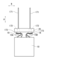
- FIG. 4 is a side view showing a wound body 10 having a first connection portion 16A connecting a first external lead 17A to a first internal lead 15A, and a second connection portion 16B connecting a second external lead 17B to a second internal lead 15B.
- Figure 5 is a side view showing the wound body 10 after the insertion process.
- Figure 6 is a cross-sectional side view of the bottomed case 60 and sealing member 20 of the completed electrolytic capacitor 100.
- the insertion process is performed after orienting the extension direction of the laminated portion (i.e., the first connection portion 16A and the second connection portion 16B) in the second direction (arrow B) and orienting the extension direction of the first external lead 17A and the second external lead 17B in the first direction (arrow A).
- FIG. 7 is a partial schematic diagram of the side of the external lead 17 showing variations in the flange.
- multiple pointed protrusions 173a are provided on the surface of the flange 173 facing the second surface S2 of the laminated portion.
- multiple spherical protrusions 173b are provided on the surface of the flange 173 facing the second surface S2 of the laminated portion.
- FIG. 7(c) shows a flange 173A having multiple projections and recesses on the surface facing the second surface S2 of the laminated portion. All of these flanges are useful for reducing the connection resistance between the external lead and the internal lead and more significantly increasing the allowable ripple current value.
- FIG. 8 is a schematic cross-sectional view illustrating another example of the second connection step of connecting an external lead to an internal lead, which is a modified example of the second connection step described with reference to FIG. 3.
- a washer 19 is used.
- the washer 19 is arranged on the first surface S1 of the laminated portion so as to surround the edge of the through hole 15a.
- the laminated portion or the portion defining the inner circumferential surface of the through hole 15a of the internal lead 15 is pushed up by the columnar portion 172 and plastically deformed so as to expand the diameter of the through hole 15a.
- the vicinity of the inner circumferential surface of the through hole 15a protrudes from the second surface S2 side toward the first surface S1 side.
- the first portion 18 protruding from the first surface S1 of the laminate is crushed toward the first surface S1 of the laminate.
- the vicinity of the inner peripheral surface of the internal lead 15 protruding toward the first surface S1 is folded back to the first surface S1 via the washer 19.
- the washer 19 By using the washer 19, the compressive stress on the vicinity of the inner peripheral surface of the laminate during the deformation of the first portion 18 is significantly increased. As shown in FIG.
- the second portion 182 when the crushing of the first portion 18 is completed and the top portion 181 formed by the deformation of the first portion 18, the second portion 182 penetrating the laminate, and the third portion 183 protruding from the second surface of the laminate are formed, the second portion 182 is in highly dense contact with the inner peripheral surface of the laminate.
- This disclosure can be used for electrolytic capacitors.
- it is suitable for use in electrolytic capacitors (e.g., solid-liquid hybrid electrolytic capacitors) used in applications requiring low ESR and improved allowable ripple current.
- Electrolytic capacitor 10 Wound body 11A First electrode foil 11B Second electrode foil 13 Separator 14 Stop tape 15A First internal lead 15B Second internal lead 15a Through hole 16A First connection portion 16B Second connection portion 17A First external lead 17B Second external lead 171 Lead body portion 172 Columnar portion 173, 173A Flange portion 173a, 173b Projection portion 18 First portion 181 Top portion 182 Second portion 183 Third portion 20 Sealing material 60 Bottomed case
Landscapes
- Engineering & Computer Science (AREA)
- Power Engineering (AREA)
- Microelectronics & Electronic Packaging (AREA)
- Fixed Capacitors And Capacitor Manufacturing Machines (AREA)
Priority Applications (2)
| Application Number | Priority Date | Filing Date | Title |
|---|---|---|---|
| JP2025511214A JPWO2024204627A1 (https=) | 2023-03-29 | 2024-03-28 | |
| CN202480022346.3A CN120898262A (zh) | 2023-03-29 | 2024-03-28 | 电解电容器及其制造方法 |
Applications Claiming Priority (2)
| Application Number | Priority Date | Filing Date | Title |
|---|---|---|---|
| JP2023-053815 | 2023-03-29 | ||
| JP2023053815 | 2023-03-29 |
Publications (1)
| Publication Number | Publication Date |
|---|---|
| WO2024204627A1 true WO2024204627A1 (ja) | 2024-10-03 |
Family
ID=92905877
Family Applications (1)
| Application Number | Title | Priority Date | Filing Date |
|---|---|---|---|
| PCT/JP2024/012853 Ceased WO2024204627A1 (ja) | 2023-03-29 | 2024-03-28 | 電解コンデンサおよびその製造方法 |
Country Status (3)
| Country | Link |
|---|---|
| JP (1) | JPWO2024204627A1 (https=) |
| CN (1) | CN120898262A (https=) |
| WO (1) | WO2024204627A1 (https=) |
Citations (5)
| Publication number | Priority date | Publication date | Assignee | Title |
|---|---|---|---|---|
| JPS56129318A (en) * | 1980-03-14 | 1981-10-09 | Nichicon Capacitor Ltd | Lead terminal connecting device |
| JPH10229032A (ja) * | 1997-02-14 | 1998-08-25 | Nippon Chemicon Corp | コンデンサ素子の端子構造 |
| JP2001284173A (ja) * | 2000-03-31 | 2001-10-12 | Nippon Chemicon Corp | 電解コンデンサ |
| JP2003282364A (ja) * | 2002-03-25 | 2003-10-03 | Jcc Engineering Co Ltd | 端子付き電極箔並びにその製造方法及び装置 |
| WO2021172440A1 (ja) * | 2020-02-28 | 2021-09-02 | パナソニックIpマネジメント株式会社 | 電解コンデンサおよびその製造方法 |
-
2024
- 2024-03-28 JP JP2025511214A patent/JPWO2024204627A1/ja active Pending
- 2024-03-28 WO PCT/JP2024/012853 patent/WO2024204627A1/ja not_active Ceased
- 2024-03-28 CN CN202480022346.3A patent/CN120898262A/zh active Pending
Patent Citations (5)
| Publication number | Priority date | Publication date | Assignee | Title |
|---|---|---|---|---|
| JPS56129318A (en) * | 1980-03-14 | 1981-10-09 | Nichicon Capacitor Ltd | Lead terminal connecting device |
| JPH10229032A (ja) * | 1997-02-14 | 1998-08-25 | Nippon Chemicon Corp | コンデンサ素子の端子構造 |
| JP2001284173A (ja) * | 2000-03-31 | 2001-10-12 | Nippon Chemicon Corp | 電解コンデンサ |
| JP2003282364A (ja) * | 2002-03-25 | 2003-10-03 | Jcc Engineering Co Ltd | 端子付き電極箔並びにその製造方法及び装置 |
| WO2021172440A1 (ja) * | 2020-02-28 | 2021-09-02 | パナソニックIpマネジメント株式会社 | 電解コンデンサおよびその製造方法 |
Also Published As
| Publication number | Publication date |
|---|---|
| JPWO2024204627A1 (https=) | 2024-10-03 |
| CN120898262A (zh) | 2025-11-04 |
Similar Documents
| Publication | Publication Date | Title |
|---|---|---|
| US11094471B2 (en) | Electrolytic capacitor | |
| JP5137604B2 (ja) | 電解コンデンサとその製造方法 | |
| US12112900B2 (en) | Electrolytic capacitor | |
| CN106133861B (zh) | 电解电容器 | |
| JPWO2016189779A1 (ja) | 電解コンデンサ | |
| US12308180B2 (en) | Electrolytic capacitor and method for producing same | |
| WO2017163725A1 (ja) | 電解コンデンサおよびその製造方法 | |
| JP2005190913A (ja) | リチウム二次電池 | |
| WO2024204627A1 (ja) | 電解コンデンサおよびその製造方法 | |
| JP6726886B2 (ja) | 電解コンデンサおよびその製造方法 | |
| JP4895028B2 (ja) | 電気二重層キャパシタ | |
| JP6191015B2 (ja) | 電解コンデンサ | |
| WO2024162158A1 (ja) | 電解コンデンサおよびその製造方法 | |
| JP2009188321A (ja) | 電解コンデンサ | |
| US20250201987A1 (en) | Electricity storage device | |
| JP7645463B2 (ja) | 電解コンデンサおよびその製造方法 | |
| JP2004153259A (ja) | 電気二重層キャパシタ及び該電気二重層キャパシタの製造方法 | |
| JP2025043997A (ja) | 電解コンデンサの製造方法および電解コンデンサ | |
| JP2001284190A (ja) | 固体電解コンデンサ | |
| HK1169512B (en) | Volumetrically efficient wet electrolytic capacitor | |
| HK1169512A1 (zh) | 体积高效的湿式电解电容器 | |
| HK1168193B (en) | Leadwire configuration for a planar anode of a wet electrolytic capacitor | |
| HK1168193A1 (zh) | 用於湿式电解电容器的平板式阳极的引线结构 |
Legal Events
| Date | Code | Title | Description |
|---|---|---|---|
| 121 | Ep: the epo has been informed by wipo that ep was designated in this application |
Ref document number: 24780726 Country of ref document: EP Kind code of ref document: A1 |
|
| ENP | Entry into the national phase |
Ref document number: 2025511214 Country of ref document: JP Kind code of ref document: A |
|
| WWE | Wipo information: entry into national phase |
Ref document number: 2025511214 Country of ref document: JP |
|
| WWE | Wipo information: entry into national phase |
Ref document number: 202480022346.3 Country of ref document: CN |
|
| NENP | Non-entry into the national phase |
Ref country code: DE |
|
| WWP | Wipo information: published in national office |
Ref document number: 202480022346.3 Country of ref document: CN |
|
| 122 | Ep: pct application non-entry in european phase |
Ref document number: 24780726 Country of ref document: EP Kind code of ref document: A1 |