WO2024204282A1 - 二次電池用正極および二次電池 - Google Patents
二次電池用正極および二次電池 Download PDFInfo
- Publication number
- WO2024204282A1 WO2024204282A1 PCT/JP2024/012118 JP2024012118W WO2024204282A1 WO 2024204282 A1 WO2024204282 A1 WO 2024204282A1 JP 2024012118 W JP2024012118 W JP 2024012118W WO 2024204282 A1 WO2024204282 A1 WO 2024204282A1
- Authority
- WO
- WIPO (PCT)
- Prior art keywords
- positive electrode
- active material
- electrode active
- material layer
- secondary battery
- Prior art date
- Legal status (The legal status is an assumption and is not a legal conclusion. Google has not performed a legal analysis and makes no representation as to the accuracy of the status listed.)
- Ceased
Links
Images


Classifications
-
- H—ELECTRICITY
- H01—ELECTRIC ELEMENTS
- H01M—PROCESSES OR MEANS, e.g. BATTERIES, FOR THE DIRECT CONVERSION OF CHEMICAL ENERGY INTO ELECTRICAL ENERGY
- H01M10/00—Secondary cells; Manufacture thereof
- H01M10/05—Accumulators with non-aqueous electrolyte
- H01M10/052—Li-accumulators
- H01M10/0525—Rocking-chair batteries, i.e. batteries with lithium insertion or intercalation in both electrodes; Lithium-ion batteries
-
- H—ELECTRICITY
- H01—ELECTRIC ELEMENTS
- H01M—PROCESSES OR MEANS, e.g. BATTERIES, FOR THE DIRECT CONVERSION OF CHEMICAL ENERGY INTO ELECTRICAL ENERGY
- H01M4/00—Electrodes
- H01M4/02—Electrodes composed of, or comprising, active material
- H01M4/13—Electrodes for accumulators with non-aqueous electrolyte, e.g. for lithium-accumulators; Processes of manufacture thereof
-
- H—ELECTRICITY
- H01—ELECTRIC ELEMENTS
- H01M—PROCESSES OR MEANS, e.g. BATTERIES, FOR THE DIRECT CONVERSION OF CHEMICAL ENERGY INTO ELECTRICAL ENERGY
- H01M4/00—Electrodes
- H01M4/02—Electrodes composed of, or comprising, active material
- H01M4/62—Selection of inactive substances as ingredients for active masses, e.g. binders, fillers
- H01M4/624—Electric conductive fillers
- H01M4/625—Carbon or graphite
-
- H—ELECTRICITY
- H01—ELECTRIC ELEMENTS
- H01M—PROCESSES OR MEANS, e.g. BATTERIES, FOR THE DIRECT CONVERSION OF CHEMICAL ENERGY INTO ELECTRICAL ENERGY
- H01M4/00—Electrodes
- H01M4/02—Electrodes composed of, or comprising, active material
- H01M2004/021—Physical characteristics, e.g. porosity, surface area
-
- H—ELECTRICITY
- H01—ELECTRIC ELEMENTS
- H01M—PROCESSES OR MEANS, e.g. BATTERIES, FOR THE DIRECT CONVERSION OF CHEMICAL ENERGY INTO ELECTRICAL ENERGY
- H01M4/00—Electrodes
- H01M4/02—Electrodes composed of, or comprising, active material
- H01M2004/026—Electrodes composed of, or comprising, active material characterised by the polarity
- H01M2004/028—Positive electrodes
-
- Y—GENERAL TAGGING OF NEW TECHNOLOGICAL DEVELOPMENTS; GENERAL TAGGING OF CROSS-SECTIONAL TECHNOLOGIES SPANNING OVER SEVERAL SECTIONS OF THE IPC; TECHNICAL SUBJECTS COVERED BY FORMER USPC CROSS-REFERENCE ART COLLECTIONS [XRACs] AND DIGESTS
- Y02—TECHNOLOGIES OR APPLICATIONS FOR MITIGATION OR ADAPTATION AGAINST CLIMATE CHANGE
- Y02E—REDUCTION OF GREENHOUSE GAS [GHG] EMISSIONS, RELATED TO ENERGY GENERATION, TRANSMISSION OR DISTRIBUTION
- Y02E60/00—Enabling technologies; Technologies with a potential or indirect contribution to GHG emissions mitigation
- Y02E60/10—Energy storage using batteries
Definitions
- This technology relates to positive electrodes for secondary batteries and secondary batteries.
- secondary batteries are being developed as small, lightweight power sources that can provide high energy density.
- These secondary batteries contain a positive electrode (positive electrode for secondary batteries) and a negative electrode as well as an electrolyte, and various studies are being conducted on the configuration of these secondary batteries.
- the positive electrode material layer contains a conductive material, and the Raman peak integrated intensity ratio for the positive electrode material layer is greater than 0.6 and is in the range of 10 or less (see, for example, Patent Document 1).
- the positive electrode contains carbon black, non-fibrous graphite particles, and fibrous carbon (see, for example, Patent Document 2).
- the battery electrode contains carbon nanotubes and a non-fibrous conductive carbon material (see, for example, Patent Document 3).
- the positive electrode composite layer contains carbon black, a first carbon nanotube with a small fiber length, and a second carbon nanotube with a large fiber length (see, for example, Patent Document 4).
- the positive electrode for a secondary battery includes a positive electrode active material layer.
- the positive electrode active material layer includes a positive electrode active material and a positive electrode conductive agent, and the positive electrode conductive agent includes a carbon material.
- the half-width of a peak identified based on the results of an analysis of the surface of the positive electrode active material layer using Raman spectroscopy according to the steps (1) to (3) below is 0.50 or less.
- the surface of the positive electrode active material layer is analyzed using Raman spectroscopy to obtain a Raman mapping of the D/G ratio.
- a histogram of the D/G ratio having a peak is obtained.
- the secondary battery of one embodiment of the present technology includes a positive electrode, a negative electrode, and an electrolyte, and the positive electrode has a configuration similar to that of the positive electrode for the secondary battery of one embodiment of the present technology described above.
- the "D/G ratio” is the integrated intensity ratio of two types of peaks (D-band peak and G-band peak) detected when the surface of the positive electrode active material layer is analyzed using Raman spectroscopy.
- the D-band peak is a peak detected within a Raman shift range of about 1300 cm -1 to 1400 cm -1
- the G-band peak is a peak detected within a Raman shift range of about 1550 cm -1 to 1650 cm -1 .
- the "half-width” is determined based on the results of an analysis of the surface of the positive electrode active material layer using Raman spectroscopy (Raman mapping and histogram). This half-width is the so-called full width at half maximum (FWHM). The procedure for determining the half-width will be described in detail later.
- the positive electrode active material layer contains a positive electrode active material and a positive electrode conductive agent, and the positive electrode conductive agent contains a carbon material, and the half-width of the peak identified based on the results of an analysis of the surface of the positive electrode active material layer using Raman spectroscopy is 0.50 or less, so that excellent battery characteristics can be obtained.
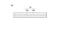
- FIG. 1 is a cross-sectional view illustrating a configuration of a positive electrode for a secondary battery according to an embodiment of the present technology.
- FIG. 2 is a diagram showing an example of a histogram acquired based on Raman mapping.
- FIG. 3 is a perspective view illustrating a configuration of a secondary battery according to an embodiment of the present technology.
- FIG. 4 is a cross-sectional view showing the configuration of the battery element shown in FIG.
- FIG. 5 is a block diagram showing a configuration of an application example of a secondary battery.
- FIG. 6 is a cross-sectional view showing the structure of a test secondary battery.
- Positive electrode for secondary battery 1-1 Structure 1-2. Physical properties 1-3. Operation 1-4. Manufacturing method 1-5. Action and effect 2. Secondary battery 2-1. Structure 2-2. Operation 2-3. Manufacturing method 2-4. Action and effect 3. Modification 4. Uses of secondary battery
- Positive electrode for secondary batteries First, a positive electrode for a secondary battery (hereinafter simply referred to as a "positive electrode") according to an embodiment of the present technology will be described.
- the positive electrode described here is used in a secondary battery, which is an electrochemical device.
- the positive electrode may also be used in electrochemical devices other than secondary batteries. Examples of other electrochemical devices include primary batteries and capacitors.
- This positive electrode absorbs and releases an electrode reactant during operation of the electrochemical device (electrode reaction).
- the type of electrode reactant is not particularly limited, but specifically, it is a light metal such as an alkali metal or an alkaline earth metal.
- alkali metals include lithium, sodium, and potassium
- alkaline earth metals include beryllium, magnesium, and calcium.
- the electrode reactant is lithium.
- lithium is absorbed and released in an ionic state at the positive electrode during the electrode reaction.
- FIG. 1 shows a cross-sectional structure of a positive electrode 100 which is a specific example of the positive electrode.
- the positive electrode 100 includes a positive electrode active material layer 100B.
- the positive electrode 100 further includes a positive electrode current collector 100A that supports the positive electrode active material layer 100B.
- the positive electrode current collector 100A is a conductive support that supports the positive electrode active material layer 100B, and has a pair of surfaces (upper and lower surfaces) on which the positive electrode active material layer 100B is provided.
- the positive electrode current collector 100A contains a conductive material such as a metal material, and a specific example of the conductive material is aluminum.
- the positive electrode active material layer 100B is a layer that absorbs and releases lithium, and is provided on one surface (upper surface or lower surface) of the positive electrode current collector 100A. However, the positive electrode active material layer 100B may be provided on both surfaces (upper surface and lower surface) of the positive electrode current collector 100A.
- This positive electrode active material layer 100B contains a positive electrode active material and a positive electrode conductive agent.
- the positive electrode active material is one or more of materials that absorb and release lithium.
- the type of the positive electrode active material is not particularly limited, but specifically, it is a lithium-containing compound, etc. This is because a high voltage can be obtained.
- This lithium-containing compound is a compound that contains lithium as well as one or more transition metal elements as constituent elements, and may further contain one or more other elements (excluding lithium and transition metal elements) as constituent elements.
- the type of other element is not particularly limited, but specifically, it is an element belonging to groups 2 to 15 of the long periodic table.
- the type of lithium-containing compound is not particularly limited, but specifically, it is an oxide, a phosphate compound, a silicate compound, a borate compound, etc.
- oxides include LiNiO2 , LiCoO2 , LiCo0.98Al0.01Mg0.01O2 , LiNi0.5Co0.2Mn0.3O2 , and LiMn2O4 .
- phosphate compounds include LiFePO4 , LiMnPO4 , and LiFe0.5Mn0.5PO4 .
- the positive electrode conductive agent is a material that improves the conductivity of the positive electrode active material layer 100B, and contains one or more types of carbon materials that are conductive materials.
- the type of carbon material is not particularly limited, but specifically, it is one or both of particulate carbon material and fibrous carbon material. That is, the positive electrode conductive agent may contain only particulate carbon material, may contain only fibrous carbon material, or may contain both particulate carbon material and fibrous carbon material.
- the type of particulate carbon material may be only one type, or two or more types.
- the type of fibrous carbon material may be only one type, or two or more types.
- particulate carbon materials include graphite, carbon black, acetylene black, and ketjen black.
- fibrous carbon materials include carbon nanotubes, carbon fibers, and carbon nanofibers.
- the carbon material contains both particulate carbon material and fibrous carbon material, since this further improves the conductivity of the positive electrode active material layer 100B.
- the particulate carbon material when the carbon material contains both particulate carbon material and fibrous carbon material, the particulate carbon material is more likely to be arranged on the surface of the positive electrode active material, and the fibrous carbon material is more likely to be arranged to cross multiple positive electrode active materials using the particulate carbon material as a binding point.
- This makes it easier to form a conductive network using the positive electrode active material, particulate carbon material, and fibrous carbon material in the positive electrode active material layer 100B.
- the carbon material when the carbon material contains only one of the particulate carbon material and the fibrous carbon material, the conductive network described above is less likely to be formed.
- the physical properties of the positive electrode active material layer 100B which contains a carbon material as a positive electrode conductive agent, are optimized, improving the dispersibility of the positive electrode conductive agent inside the positive electrode active material layer 100B.
- the physical properties of the positive electrode active material layer 100B described here will be described in detail later.
- the positive electrode conductive agent may further contain one or more of other conductive materials, such as metal materials and conductive polymer compounds.
- the positive electrode active material layer 100B may further include a positive electrode binder.
- the positive electrode binder is a material that binds the positive electrode active material and the positive electrode conductive agent to each other, and includes one or more of materials such as synthetic rubber and polymer compounds.
- synthetic rubber include styrene butadiene rubber, fluorine-based rubber, and ethylene propylene diene.
- polymer compounds include polyvinylidene fluoride, polyimide, and carboxymethyl cellulose.
- Physical properties> 2 shows an example of a histogram obtained based on Raman mapping, in which the horizontal axis indicates the D/G ratio and the vertical axis indicates the frequency.
- the physical properties of the positive electrode active material layer 100B, which contains a carbon material as a positive electrode conductive agent, are optimized.
- the half-width HW of the peak P which is determined based on the results of an analysis of the surface of the positive electrode active material layer 100B using Raman spectroscopy according to the steps (1) to (3) below, is 0.50 or less.
- the value of the half-width HW is rounded off to two decimal places.
- the surface of the positive electrode active material layer 100B is analyzed using Raman spectroscopy to obtain a Raman mapping of the D/G ratio.
- a histogram of the D/G ratio having a peak P is obtained.
- the half-width HW of the peak P is calculated.
- the "D/G ratio” is the integrated intensity ratio of two types of peaks (D-band peak and G-band peak) detected when the surface of the positive electrode active material layer 100B is analyzed using Raman spectroscopy, as described above.
- the D-band peak is a peak detected within a Raman shift range of approximately 1300 cm -1 to 1400 cm -1
- the G-band peak is a peak detected within a Raman shift range of approximately 1550 cm -1 to 1650 cm -1 .
- the "half width HW” is determined based on the analysis results (Raman mapping and histogram) of the surface of the positive electrode active material layer 100B using Raman spectroscopy. This half width is the so-called full width at half maximum (FWHM).
- the detailed procedure for determining the half-value width HW is as follows. Below, the procedure for determining the half-value width HW is explained for each of the steps (1) to (3).
- the surface of the positive electrode active material layer 100B is analyzed using Raman spectroscopy to obtain a Raman mapping of the D/G ratio.
- a laser Raman microscope RAMANforce manufactured by Nanophoton Co., Ltd. can be used as the Raman spectroscopic analyzer.
- the analysis conditions are an analysis range of 100 ⁇ m ⁇ 100 ⁇ m and an excitation wavelength of 532 nm.
- Raman mapping is the result of using Raman spectroscopy to analyze the surface of the positive electrode active material layer 100B to calculate the D/G ratio, which is then displayed (mapped) two-dimensionally.
- Raman mapping is the result of visualizing the distribution of the crystalline state of the carbon material identified based on the D/G ratio.
- This histogram is the result of graphing Raman mapping to continuously display the change in frequency of the D/G ratio.
- the frequency of the D/G ratio increases and then decreases, so peak P is detected.
- Raman spectroscopy is used to analyze the surface of the positive electrode active material layer 100B at 10 different locations, and 10 half-widths are calculated based on the analysis results of the 10 locations (10 Raman mappings and 10 histograms), and the average of the 10 half-widths is taken as the half-width HW.
- the half-width HW is 0.5 or less because the dispersion of the positive electrode conductive agent inside the positive electrode active material layer 100B is improved, and the D/G ratio is uniformly distributed inside the positive electrode active material layer 100B.
- the electrical resistance and physical strength are uniformed inside the positive electrode active material layer 100B.
- the half-width HW is 0.5 or less is that, as described below, when preparing the positive electrode composite slurry in the manufacturing process of the positive electrode 100, the positive electrode conductor is added to the solvent containing the positive electrode active material with a time lag while the solvent is being stirred. In other words, the positive electrode active material and the positive electrode conductor are not added to the solvent together, but after the positive electrode active material is added to the solvent, the positive electrode conductor is added separately to the solvent.
- the half-width HW can be controlled to the desired value by adjusting the stirring conditions such as the stirring speed and stirring time.
- the positive electrode binder as described above with respect to the positive electrode conductor.
- the positive electrode active material layer 100B contains a positive electrode binder
- the positive electrode conductor and the positive electrode binder are added to a solvent containing the positive electrode active material with a time lag while the solvent is stirred.
- the positive electrode conductor and the positive electrode binder instead of adding the positive electrode active material, the positive electrode conductor, and the positive electrode binder together to the solvent, only one of the positive electrode conductor and the positive electrode binder is added to the solvent containing the positive electrode active material, and then the other of the positive electrode conductor and the positive electrode binder is added separately.
- a positive electrode mixture slurry is prepared according to the procedure described below as an example, and then the positive electrode 100 is produced using the positive electrode mixture slurry.
- the positive electrode active material layer 100B is formed using a positive electrode mixture slurry that contains a positive electrode binder together with a positive electrode active material and a positive electrode conductive agent.
- the type of solvent is not particularly limited, and may be an aqueous solvent or a non-aqueous solvent (organic solvent).
- a stirrer such as a planetary mixer, homogenizer, or ball mill may be used to stir the solvent.
- Stirring conditions such as the stirring speed (rotation speed of the stirrer (rpm)) and stirring time (minutes) can be set arbitrarily.
- the reason why the positive electrode conductive agent and the positive electrode binder are added at different times to prepare the positive electrode mixture slurry is that the dispersion of the positive electrode conductive agent in the positive electrode mixture slurry is improved, so that the half-width HW falls within the above-mentioned range.
- the dispersibility of the positive electrode conductive agent in the first dispersion liquid is improved compared to when both the positive electrode conductive agent and the positive electrode binder are added to the first dispersion liquid together. This makes it easier for the positive electrode conductive agent to be uniformly dispersed in the first dispersion liquid.
- the advantages of the positive electrode conductive agent described here can also be obtained for the positive electrode binder. That is, by adding only the positive electrode binder to the first dispersion liquid separately from the positive electrode conductive agent, the dispersibility of the positive electrode binder in the first dispersion liquid is improved compared to when both the positive electrode binder and the positive electrode conductive agent are added to the first dispersion liquid together. This makes it easier for the positive electrode binder to be dissolved uniformly in the first dispersion liquid.
- the dispersion of the positive electrode conductive agent is improved inside the positive electrode active material layer 100B formed using the positive electrode mixture slurry in a later process.
- the D/G ratio is more likely to be distributed uniformly, and the half-value width HW falls within the above-mentioned range.
- the advantages of preparing the first dispersion described here are similarly obtained when preparing the second dispersion. That is, by adding only the positive electrode conductive agent to the second dispersion separately from the positive electrode binder, the dispersibility of the positive electrode conductive agent in the second dispersion is improved, so that the positive electrode conductive agent is more likely to be uniformly dispersed in the second dispersion. Also, by adding only the positive electrode binder to the second dispersion separately from the positive electrode conductive agent, the solubility of the positive electrode binder in the second dispersion is improved, so that the positive electrode binder is more likely to be uniformly dissolved in the second dispersion.
- a dispersion liquid in which the positive electrode conductive agent is already dispersed in a solvent may be added to the first dispersion liquid. This is because the dispersibility of the positive electrode conductive agent in the first dispersion liquid is improved. Details regarding the solvent are as described above.
- a dispersion in which the positive electrode conductive agent is already dispersed in a solvent may be added to the second dispersion.
- a solution in which the positive electrode binder is dissolved in a solvent beforehand may be added to the first dispersion liquid. This is because the dispersibility of the positive electrode binder in the first dispersion liquid is improved. Details regarding the solvent are as described above.
- a dispersion in which the positive electrode conductive agent is already dispersed in a solvent may be added to the second dispersion.
- the order in which the positive electrode binder and the two types of positive electrode conductive agents are added may be any of the orders described below.
- a positive electrode binder may be added, (2) a first type of positive electrode conductive agent may be added, and (3) a second type of positive electrode conductive agent may be added.
- a positive electrode binder may be added, (2) a second type of positive electrode conductive agent may be added, and (3) the first type of positive electrode conductive agent may be added.
- a first type of positive electrode conductive agent may be added, (2) a positive electrode binder may be added, and (3) a second type of positive electrode conductive agent may be added.
- a first type of positive electrode conductive agent may be added, (2) a second type of positive electrode conductive agent may be added, and (3) a positive electrode binder may be added.
- a second type of positive electrode conductive agent may be added, (2) a positive electrode binder may be added, and (3) a first type of positive electrode conductive agent may be added.
- a second type of positive electrode conductive agent may be added, (2) a first type of positive electrode conductive agent may be added, and (3) a positive electrode binder may be added.
- the positive electrode 100 is produced using the positive electrode mixture slurry
- the positive electrode mixture slurry is applied to one side of the positive electrode current collector 100A to form the positive electrode active material layer 100B.
- the positive electrode active material layer 100B may then be compression molded using a molding machine such as a roll press. In this case, the positive electrode active material layer 100B may be heated, or the compression molding may be repeated multiple times.
- the positive electrode active material layer 100B is formed on one side of the positive electrode current collector 100A, completing the positive electrode 100.
- the positive electrode active material layer 100B contains a positive electrode active material and a positive electrode conductive agent, the positive electrode conductive agent contains a carbon material, and the half width HW of the peak P identified based on the analysis results of the surface of the positive electrode active material layer 100B using Raman spectroscopy is 0.5 or less.
- the dispersibility of the positive electrode conductive agent inside the positive electrode active material layer 100B is improved, and the D/G ratio tends to be distributed uniformly. This makes the electrical resistance and physical strength uniform inside the positive electrode active material layer 100B. Therefore, when the secondary battery using the positive electrode 100 is charged and discharged, lithium tends to be absorbed and released uniformly inside the positive electrode active material layer 100B, and the positive electrode active material layer 100B tends to expand and contract uniformly.
- the positive electrode active material layer 100B is less likely to deteriorate or be damaged even when the secondary battery is repeatedly charged and discharged, so that a secondary battery with excellent battery characteristics can be realized by using the positive electrode 100.
- the carbon material contains particulate carbon material and fibrous carbon material
- a conductive network using the positive electrode active material, particulate carbon material, and fibrous carbon material is easily formed in the positive electrode active material layer 100B. This further improves the conductivity of the positive electrode active material layer 100B, thereby achieving a greater effect.
- the half-width HW is controlled to be within the above-mentioned range, and the binding property of the positive electrode active material and the positive electrode conductive agent is improved, so that a higher effect can be obtained.
- the secondary battery described here is a secondary battery that obtains battery capacity by utilizing the absorption and release of an electrode reactant, and is equipped with a positive electrode, a negative electrode, and an electrolyte.
- the electrode reactant is lithium.
- a secondary battery that obtains battery capacity by utilizing the absorption and release of lithium is a so-called lithium-ion secondary battery. In this lithium-ion secondary battery, lithium is absorbed and released in an ionic state.
- the charge capacity of the negative electrode is preferably greater than the discharge capacity of the positive electrode.
- the electrochemical capacity per unit area of the negative electrode is preferably greater than the electrochemical capacity per unit area of the positive electrode. This is to prevent lithium from being deposited on the surface of the negative electrode during charging.
- Fig. 3 shows a perspective view of the secondary battery
- Fig. 4 shows an enlarged cross-sectional view of the battery element 20 shown in Fig. 3.
- Fig. 3 shows a state in which the exterior film 10 and the battery element 20 are separated from each other, and the cross section of the battery element 20 taken along the XZ plane is shown by a broken line.
- Fig. 4 shows only a part of the battery element 20.
- This secondary battery includes an exterior film 10, a battery element 20, a positive electrode lead 31, a negative electrode lead 32, and sealing films 41 and 42.
- the secondary battery described here is a laminate film type secondary battery that uses a flexible or pliable exterior film 10 as an exterior member for housing the battery element 20.
- the exterior film 10 has a bag-like structure that is sealed with the battery element 20 housed therein. As a result, the exterior film 10 houses an electrolyte together with a positive electrode 21 and a negative electrode 22, which will be described later.
- the exterior film 10 is a single film-like member that is folded in the folding direction F.
- This exterior film 10 is provided with a recessed portion 10U (a so-called deep drawn portion) for accommodating the battery element 20.
- the exterior film 10 is a three-layer laminate film in which a fusion layer, a metal layer, and a surface protection layer are laminated in this order from the inside, and when the exterior film 10 is folded, the outer peripheral edges of the opposing fusion layers are fused to each other.
- the fusion layer contains a polymer compound such as polypropylene.
- the metal layer contains a metallic material such as aluminum.
- the surface protection layer contains a polymer compound such as nylon.
- the configuration (number of layers) of the exterior film 10, which is a laminate film is not particularly limited, and may be one or two layers, or four or more layers.
- the battery element 20 is a power generating element including a positive electrode 21 , a negative electrode 22 , a separator 23 , and an electrolyte (not shown), and is housed inside the exterior film 10 .
- This battery element 20 is a so-called wound electrode body, so the positive electrode 21 and the negative electrode 22 are wound around the winding axis P while facing each other via the separator 23.
- This winding axis P is a virtual axis that extends in the Y-axis direction.
- the three-dimensional shape of the battery element 20 is not particularly limited.
- the battery element 20 is flat, and therefore the shape of the cross section (cross section along the XZ plane) of the battery element 20 intersecting the winding axis P is a flat shape defined by the long axis J1 and the short axis J2.
- the long axis J1 is an imaginary axis that extends in the X-axis direction and has a length greater than the length of the short axis J2
- the short axis J2 is an imaginary axis that extends in the Z-axis direction intersecting the X-axis direction and has a length smaller than the length of the long axis J1.
- the three-dimensional shape of the battery element 20 is a flat cylindrical shape, and therefore the shape of the cross section of the battery element 20 is a flattened approximate ellipse.
- the positive electrode 21 has a configuration similar to that of the positive electrode 100 .
- the positive electrode 21 includes a positive electrode collector 21A and a positive electrode active material layer 21B.
- the configuration of the positive electrode collector 21A is similar to that of the positive electrode collector 100A, and the configuration of the positive electrode active material layer 21B is similar to that of the positive electrode active material layer 100B.
- the positive electrode active material layer 21B is provided on both sides of the positive electrode collector 21A.
- the negative electrode 22 includes a negative electrode current collector 22A and a negative electrode active material layer 22B.
- the negative electrode current collector 22A has a pair of surfaces on which the negative electrode active material layer 22B is provided.
- This negative electrode current collector 22A contains a conductive material such as a metal material, and a specific example of the conductive material is copper.
- the negative electrode active material layer 22B contains one or more types of negative electrode active materials that absorb and release lithium. However, the negative electrode active material layer 22B may further contain one or more types of other materials such as a negative electrode binder and a negative electrode conductor.
- the method of forming the negative electrode active material layer 22B is not particularly limited, but specifically includes one or more types of a coating method, a gas phase method, a liquid phase method, a thermal spraying method, and a firing method (sintering method).
- the negative electrode active material layer 22B is provided on both sides of the negative electrode collector 22A.
- the negative electrode active material layer 22B may be provided on only one side of the negative electrode collector 22A on the side where the negative electrode 22 faces the positive electrode 21.
- the type of negative electrode active material is not particularly limited, but specific examples include carbon materials and metal-based materials, because they provide high energy density.
- carbon materials include graphitizable carbon, non-graphitizable carbon, and graphite (natural graphite and artificial graphite).
- the metal-based material is a material that contains one or more of metal elements and metalloid elements that can form an alloy with lithium as a constituent element, and specific examples of the metal elements and metalloid elements are silicon and tin.
- the metal-based material may be a simple substance, an alloy, a compound, a mixture of two or more of them, or a material containing two or more phases of them. However, since the simple substance may contain any amount of impurities, the purity of the simple substance is not necessarily limited to 100%.
- Specific examples of the metal-based material are TiSi 2 and SiO x (0 ⁇ x ⁇ 2, or 0.2 ⁇ x ⁇ 1.4).
- the negative electrode binder contains one or more of the following materials: synthetic rubber and polymeric compounds.
- synthetic rubber include styrene-butadiene rubber, fluororubber, and ethylene-propylene-diene.
- polymeric compounds include polyvinylidene fluoride, polyimide, and carboxymethyl cellulose.
- the negative electrode conductive agent contains one or more conductive materials such as carbon materials, metal materials, and conductive polymer compounds.
- conductive materials such as carbon materials, metal materials, and conductive polymer compounds.
- Specific examples of carbon materials include graphite, carbon black, acetylene black, and ketjen black.
- the separator 23 is an insulating porous film interposed between the positive electrode 21 and the negative electrode 22, and allows lithium ions to pass through while preventing a short circuit caused by contact between the positive electrode 21 and the negative electrode 22.
- the separator 23 contains a polymer compound such as polyethylene.
- the electrolyte is a liquid electrolyte that is impregnated into each of the positive electrode 21, the negative electrode 22, and the separator 23, and contains a solvent and an electrolyte salt.
- the solvent contains one or more types of non-aqueous solvents (organic solvents), and the electrolyte containing the non-aqueous solvent is a so-called non-aqueous electrolyte.
- the non-aqueous solvent is an ester or ether, and more specifically, a carbonate ester compound, a carboxylate ester compound, a lactone compound, etc. This is because the dissociation of the electrolyte salt is improved, and the mobility of the ions is also improved.
- Carbonate compounds include cyclic carbonates and chain carbonates. Specific examples of cyclic carbonates include ethylene carbonate and propylene carbonate, while specific examples of chain carbonates include dimethyl carbonate, diethyl carbonate, and ethyl methyl carbonate.
- Carboxylic acid ester compounds include chain carboxylates, and specific examples of chain carboxylates include ethyl acetate, ethyl propionate, propyl propionate, and ethyl trimethylacetate.
- Lactone compounds include lactones, and specific examples of lactones include ⁇ -butyrolactone and ⁇ -valerolactone.
- Ethers may also include 1,2-dimethoxyethane, tetrahydrofuran, 1,3-dioxolane, and 1,4-dioxane.
- the electrolyte salt contains one or more of light metal salts such as lithium salts.
- lithium salts include lithium hexafluorophosphate (LiPF 6 ), lithium tetrafluoroborate (LiBF 4 ), lithium trifluoromethanesulfonate (LiCF 3 SO 3 ), lithium bis(fluorosulfonyl)imide (LiN(FSO 2 ) 2 ), lithium bis(trifluoromethanesulfonyl)imide (LiN(CF 3 SO 2 ) 2 ), lithium tris(trifluoromethanesulfonyl)methide (LiC(CF 3 SO 2 ) 3 ), lithium bis(oxalato)borate (LiB(C 2 O 4 ) 2 ), lithium monofluorophosphate (Li 2 PFO 3 ), and lithium difluorophosphate (LiPF 2 O 2 ). This is because a high battery capacity can be obtained.
- the amount of electrolyte salt contained is not particularly limited, but is typically 0.3 mol/kg to 3.0 mol/kg relative to the solvent. This is because high ionic conductivity is obtained.
- the electrolyte may further contain one or more of the additives. This is because the electrochemical stability of the electrolyte is improved.
- the type of additive include unsaturated cyclic carbonates, fluorinated cyclic carbonates, sulfonates, phosphates, acid anhydrides, nitrile compounds, and isocyanate compounds.
- unsaturated cyclic carbonates include vinylene carbonate, vinylethylene carbonate, and methyleneethylene carbonate.
- fluorinated cyclic carbonates include monofluoroethylene carbonate and difluoroethylene carbonate.
- sulfonic acid esters include propane sultone and propene sultone.
- phosphate esters include trimethyl phosphate and triethyl phosphate.
- acid anhydrides include succinic anhydride, 1,2-ethanedisulfonic anhydride, and 2-sulfobenzoic anhydride.
- nitrile compounds include succinonitrile.
- isocyanate compounds include hexamethylene diisocyanate.
- the positive electrode lead 31 is a positive electrode terminal connected to the positive electrode current collector 21A, and is led out of the exterior film 10.
- the positive electrode lead 31 contains a conductive material such as a metal material, and a specific example of the conductive material is aluminum.
- the shape of the positive electrode lead 31 is not particularly limited, but is specifically either a thin plate shape or a mesh shape.
- the negative electrode lead 32 is a negative electrode terminal connected to the negative electrode current collector 22A, and is led out to the exterior of the exterior film 10.
- This negative electrode lead 32 contains a conductive material such as a metal material, and a specific example of the conductive material is copper.
- the details regarding the lead-out direction and shape of the negative electrode lead 32 are the same as the details regarding the lead-out direction and shape of the positive electrode lead 31.
- the sealing film 41 is inserted between the exterior film 10 and the positive electrode lead 31, and the sealing film 42 is inserted between the exterior film 10 and the negative electrode lead 32.
- the sealing films 41 and 42 may be omitted.
- This sealing film 41 is a sealing member that prevents outside air and the like from entering the inside of the exterior film 10.
- the sealing film 41 contains a polymer compound such as polyolefin that has adhesion to the positive electrode lead 31, and a specific example of the polyolefin is polypropylene.
- the configuration of the sealing film 42 is the same as that of the sealing film 41, except that the sealing film 42 is a sealing member that has adhesion to the negative electrode lead 32.
- the sealing film 42 contains a polymer compound such as polyolefin that has adhesion to the negative electrode lead 32.
- a secondary battery operates as follows when charging and discharging.
- lithium When charging, lithium is released from the positive electrode 21 in the battery element 20 and is absorbed in the negative electrode 22 via the electrolyte.
- discharging lithium is released from the negative electrode 22 in the battery element 20 and is absorbed in the positive electrode 21 via the electrolyte.
- charging and discharging lithium is absorbed and released in an ionic state.
- the positive electrode 21 and the negative electrode 22 are each produced and an electrolyte solution is prepared according to the procedure described below. Then, the positive electrode 21, the negative electrode 22, and the electrolyte solution are used to manufacture the secondary battery. A secondary battery is assembled and a stabilization process is performed on the secondary battery after assembly.
- the positive electrode 21 is produced by forming the positive electrode active material layers 21B on both sides of the positive electrode current collector 21A using a procedure similar to that for producing the positive electrode 100 described above.
- a mixture (negative electrode mixture) in which the negative electrode active material, the negative electrode binder, and the negative electrode conductive agent are mixed together is poured into a solvent to prepare a paste-like negative electrode mixture slurry.
- This solvent may be an aqueous solvent or a non-aqueous solvent (organic solvent).
- the negative electrode mixture slurry is applied to both sides of the negative electrode current collector 22A to form the negative electrode active material layer 22B.
- the negative electrode active material layer 22B may be compression molded. As a result, the negative electrode active material layer 22B is formed on both sides of the negative electrode current collector 22A, and the negative electrode 22 is produced.
- electrolyte solution An electrolyte salt is added to a solvent, whereby the electrolyte salt is dispersed or dissolved in the solvent, and an electrolyte solution is prepared.
- the positive electrode lead 31 is connected to the positive electrode collector 21A by using a joining method such as welding, and the negative electrode lead 32 is connected to the negative electrode collector 22A by using a joining method such as welding.
- the positive electrode 21 and the negative electrode 22 are stacked on top of each other with the separator 23 interposed therebetween, and the positive electrode 21, the negative electrode 22, and the separator 23 are wound to produce a wound body (not shown).
- the wound body is then pressed using a press or the like to form the wound body into a flat shape.
- the wound body after this formation has a configuration similar to that of the battery element 20, except that the positive electrode 21, the negative electrode 22, and the separator 23 are not impregnated with the electrolyte.
- the exterior film 10 adheresive layer/metal layer/surface protection layer
- the exterior film 10 is folded so that the exterior films 10 face each other.
- the outer edges of two of the opposing adhesive layers are joined to each other using an adhesive method such as heat fusion, thereby placing the roll inside the bag-shaped exterior film 10.
- an electrolyte is injected into the bag-shaped exterior film 10, and then the outer edges of the remaining sides of the opposing fusion layers are joined together using an adhesive method such as heat fusion.
- a sealing film 41 is inserted between the exterior film 10 and the positive electrode lead 31, and a sealing film 42 is inserted between the exterior film 10 and the negative electrode lead 32.
- the wound body is impregnated with the electrolyte, producing the battery element 20, which is a wound electrode body, and the battery element 20 is sealed inside the bag-shaped exterior film 10, thus assembling a secondary battery.
- the positive electrode 21 has a configuration similar to that of the positive electrode 100, and therefore, for the reasons described above, the positive electrode active material layer 21B is less likely to deteriorate or be damaged even if charging and discharging are repeated. Therefore, the discharge capacity is less likely to decrease even if charging and discharging are repeated, and excellent battery characteristics can be obtained.
- the secondary battery is a lithium-ion secondary battery
- sufficient battery capacity can be stably obtained by utilizing the absorption and release of lithium, resulting in even greater effects.
- the other functions and effects of the secondary battery are the same as those of the positive electrode 100.
- a porous membrane separator 23 was used. However, although not specifically shown here, a laminated separator including a polymer compound layer may also be used.
- the laminated separator includes a porous membrane having a pair of surfaces, and a polymer compound layer provided on one or both surfaces of the porous membrane. This is because the adhesion of the separator to each of the positive electrode 21 and the negative electrode 22 is improved, thereby suppressing misalignment of the battery element 20 (misalignment of the positive electrode 21, the negative electrode 22, and the separator 23). This suppresses swelling of the secondary battery even if a decomposition reaction of the electrolyte occurs.
- the polymer compound layer includes a polymer compound such as polyvinylidene fluoride. This is because polyvinylidene fluoride has excellent physical strength and is electrochemically stable.
- one or both of the porous film and the polymer compound layer may contain a plurality of insulating particles.
- the plurality of insulating particles contain one or more types of insulating materials such as inorganic materials and resin materials.
- inorganic materials include aluminum oxide, aluminum nitride, boehmite, silicon oxide, titanium oxide, magnesium oxide, and zirconium oxide.
- resin materials include acrylic resin and styrene resin.
- a precursor solution containing a polymer compound and a solvent is prepared, and then the precursor solution is applied to one or both sides of a porous film.
- multiple insulating particles may be added to the precursor solution as necessary.
- a positive electrode 21 and a negative electrode 22 are wound facing each other with a separator 23 and an electrolyte layer interposed between them.
- the electrolyte layer is interposed between the positive electrode 21 and the separator 23, and also between the negative electrode 22 and the separator 23.
- the electrolyte layer contains a polymer compound together with an electrolyte solution, and the electrolyte solution is held by the polymer compound. This is because leakage of the electrolyte solution is prevented.
- the composition of the electrolyte solution is as described above.
- the polymer compound contains polyvinylidene fluoride and the like.
- the use (application example) of the secondary battery is not particularly limited.
- the secondary battery used as a power source may be a main power source or an auxiliary power source in electronic devices, electric vehicles, etc.
- the main power source is a power source that is used preferentially regardless of the presence or absence of other power sources.
- the auxiliary power source may be a power source used in place of the main power source, or a power source that is switched from the main power source.
- secondary batteries are as follows: Electronic devices such as video cameras, digital still cameras, mobile phones, laptop computers, headphone stereos, portable radios, and portable information terminals. Storage devices such as backup power sources and memory cards. Power tools such as electric drills and power saws. Battery packs installed in electronic devices. Medical electronic devices such as pacemakers and hearing aids. Electric vehicles such as electric cars (including hybrid cars). Power storage systems such as home or industrial battery systems that store power in preparation for emergencies. In these applications, one secondary battery may be used, or multiple secondary batteries may be used.
- the battery pack may use a single cell or a battery pack.
- the electric vehicle is a vehicle that runs on a secondary battery as a driving power source, and may be a hybrid vehicle that also has a driving source other than the secondary battery.
- a home power storage system it is possible to use household electrical appliances, etc., by using the power stored in the secondary battery, which is a power storage source.
- FIG. 5 shows the block diagram of a battery pack.
- the battery pack described here is a battery pack (a so-called soft pack) that uses one secondary battery, and is installed in electronic devices such as smartphones.
- this battery pack includes a power source 51 and a circuit board 52.
- This circuit board 52 is connected to the power source 51 and includes a positive terminal 53, a negative terminal 54, and a temperature detection terminal 55.
- the power source 51 includes one secondary battery.
- the positive electrode lead is connected to the positive electrode terminal 53
- the negative electrode lead is connected to the negative electrode terminal 54.
- This power source 51 can be connected to the outside via the positive electrode terminal 53 and the negative electrode terminal 54, and therefore can be charged and discharged.
- the circuit board 52 includes a control unit 56, a switch 57, a PTC element 58, and a temperature detection unit 59. However, the PTC element 58 may be omitted.
- the control unit 56 includes a central processing unit (CPU) and memory, and controls the operation of the entire battery pack. This control unit 56 detects and controls the usage state of the power source 51 as necessary.
- CPU central processing unit
- the control unit 56 turns off the switch 57 to prevent charging current from flowing through the current path of the power source 51.
- the overcharge detection voltage is not particularly limited, but is specifically 4.20V ⁇ 0.05V.
- the overdischarge detection voltage is not particularly limited, but is specifically 2.40V ⁇ 0.1V.
- Switch 57 includes a charge control switch, a discharge control switch, a charge diode, and a discharge diode, and switches between the presence and absence of a connection between power source 51 and an external device in response to an instruction from control unit 56.
- This switch 57 includes a field effect transistor (MOSFET) that uses a metal oxide semiconductor, and the charge and discharge current is detected based on the ON resistance of switch 57.
- MOSFET field effect transistor
- the temperature detection unit 59 includes a temperature detection element such as a thermistor. This temperature detection unit 59 measures the temperature of the power supply 51 using the temperature detection terminal 55, and outputs the temperature measurement result to the control unit 56. The temperature measurement result measured by the temperature detection unit 59 is used when the control unit 56 performs charge/discharge control in the event of abnormal heat generation, and when the control unit 56 performs correction processing when calculating the remaining capacity.
- FIG. 6 shows a cross-sectional structure of a test secondary battery, which is a so-called coin-type secondary battery (lithium ion secondary battery).
- This secondary battery includes a test electrode 61, a counter electrode 62, a separator 63, an exterior cup 64, an exterior can 65, a gasket 66, and an electrolyte (not shown).
- the test electrode 61 is housed in an exterior cup 64, and the counter electrode 62 is housed in an exterior can 65.
- the test electrode 61 and the counter electrode 62 are stacked together via a separator 63, and the test electrode 61, the counter electrode 62, and the separator 63 are impregnated with an electrolyte.
- the exterior cup 64 and the exterior can 65 are crimped together via a gasket 66, so that the test electrode 61, the counter electrode 62, and the separator 63 are sealed by the exterior cup 64 and the exterior can 65.
- the secondary battery shown in Figure 6 was fabricated using the procedure described below.
- a powdered positive electrode active material LiCoO2 , a lithium-containing compound (oxide)
- a solvent N-methyl-2-pyrrolidone, an organic solvent
- the stirring conditions were a stirring speed (rotation speed) of the stirrer of 3000 rpm and a stirring time of 15 minutes.
- CB carbon black
- CNT carbon nanotubes
- PVDF Polyvinylidene fluoride
- a positive electrode conductive agent solution in which the second type of positive electrode conductive agent (carbon nanotubes) was previously dispersed in a solvent (N-methyl-2-pyrrolidone), and we also used a positive electrode binder solution in which the positive electrode binder (polyvinylidene fluoride) was previously dissolved in a solvent (N-methyl-2-pyrrolidone).
- the “Material” column in Table 1 shows the type of material added in each process.
- PVDF is the positive electrode binder (polyvinylidene fluoride)
- CB is the first type of positive electrode conductor (carbon black)
- CNT is the second type of positive electrode conductor (carbon nanotube).
- the stirring conditions (stirring speed (rpm) and stirring time (min)) in each process are as shown in Table 1.
- Example 1 the procedure for preparing the positive electrode mixture slurry in Example 1 is as follows:
- a first dispersion containing a positive electrode active material was prepared by the above-mentioned procedure.
- a first type of positive electrode conductive agent carbon black
- the first dispersion was then stirred to prepare a second dispersion (first step).
- a positive electrode binder polyvinylidene fluoride
- the second dispersion was then stirred to prepare a third dispersion (second step).
- a second type of positive electrode conductive agent carbon nanotubes
- the positive electrode 100 was fabricated using the positive electrode mixture slurry. Specifically, the positive electrode mixture slurry was applied to one side of a positive electrode current collector (aluminum foil with a thickness of 12 ⁇ m) using a coating device, and then the positive electrode mixture slurry was dried to form a positive electrode active material layer.
- a positive electrode current collector aluminum foil with a thickness of 12 ⁇ m
- test electrode 61 was produced (Examples 1 to 3 and Comparative Examples 1 to 4).
- the half-width HW was changed by changing the order of addition of a series of materials (two types of positive electrode conductors and positive electrode binder) in the process of preparing the positive electrode mixture slurry and the stirring conditions (stirring speed and stirring time) in each process, as shown in Table 1.
- the procedure for determining the half-width HW is as described above.
- test electrode 61 was prepared using a similar procedure, except that in the process of preparing the positive electrode mixture slurry, instead of adding the series of materials (two types of positive electrode conductors and a positive electrode binder) separately at different times, the series of materials were added together (Comparative Example 5).
- An electrolyte salt lithium hexafluorophosphate ( LiPF6 )
- a solvent ethylene carbonate, which is a cyclic carbonate ester, and diethyl carbonate, which is a chain carbonate ester
- the content of the electrolyte salt in the electrolyte solution was 1 mol/kg relative to the solvent. In this way, the electrolyte solution was prepared.
- test electrode 61 was accommodated in the exterior cup 64, and the counter electrode 62 was accommodated in the exterior can 65.
- the test electrode 61 accommodated in the exterior cup 64 and the counter electrode 62 accommodated in the exterior can 65 were stacked together via a separator 63 (a microporous polyethylene film having a thickness of 20 ⁇ m) impregnated with an electrolyte.
- separator 63 a microporous polyethylene film having a thickness of 20 ⁇ m impregnated with an electrolyte.
- the test electrode 61 was arranged so that the positive electrode active material layer and the counter electrode 62 faced each other via the separator 63.
- the exterior cup 64 and the exterior can 65 were crimped together via the gasket 66.
- the test electrode 61 and the counter electrode 62 were enclosed inside the exterior cup 64 and the exterior can 65, and thus a secondary battery was assembled.
- test electrode 61 and the counter electrode 62 were electrochemically stabilized, and the secondary battery was completed.
- the discharge capacity discharge capacity at the first cycle
- the discharge capacity discharge capacity at the 100th cycle
- the capacity retention values shown in Table 1 are normalized with the capacity retention value in Example 1 set to 100.
- the capacity retention rate changed according to the half-value width HW. That is, when the half-value width HW was greater than 0.50 (Comparative Examples 1-4), the capacity retention rate decreased. In contrast, when the half-value width HW was 0.50 or less (Examples 1-4), the capacity retention rate increased.
- Example 5 and Comparative Examples 6 and 7 Secondary batteries were fabricated in the same manner as in Example 1 and Comparative Examples 1 and 5, except that the type of positive electrode active material was changed as shown in Table 2, and then the battery characteristics of the secondary batteries were evaluated.
- LiNi0.82Co0.14Al0.04O2 was used instead of LiCoO2 as the lithium- containing compound ( oxide ).
- Example 6 and Comparative Example 8 Secondary batteries were fabricated in the same manner as in Example 1 and Comparative Example 5, except that the type of positive electrode conductive agent was changed as shown in Table 3, and then the battery characteristics of the secondary batteries were evaluated.
- one type of positive electrode conductive agent carbon black
- CB carbon black
- CNT carbon nanotubes
- the battery structure of the secondary battery has been described as being of a laminate film type and a coin type.
- the battery structure of the secondary battery is not particularly limited, and may be of a cylindrical type, a square type, a button type, etc.
- the battery element has been described as having a wound structure.
- the structure of the battery element is not particularly limited, and may be a stacked type or a zigzag type.
- the positive and negative electrodes are stacked on top of each other, and in the zigzag type, the positive and negative electrodes are folded in a zigzag pattern.
- the electrode reactant is described as being lithium, the electrode reactant is not particularly limited. Specifically, as described above, the electrode reactant may be other alkali metals such as sodium and potassium, or alkaline earth metals such as beryllium, magnesium and calcium. In addition, the electrode reactant may be other light metals such as aluminum.
- the present technology can also be configured as follows. ⁇ 1> a positive electrode including a positive electrode active material layer; A negative electrode; An electrolyte; the positive electrode active material layer contains a positive electrode active material and a positive electrode conductive agent, The positive electrode conductive agent includes a carbon material,
- the half-width of a peak identified based on the analysis results of the surface of the positive electrode active material layer using Raman spectroscopy according to the steps (1) to (3) below is 0.50 or less.
- Secondary battery (1) The surface of the positive electrode active material layer is analyzed using the Raman spectroscopy to obtain a Raman mapping of the D/G ratio. (2) A histogram of the D/G ratio having the peak is obtained based on the Raman mapping.
- the carbon material includes a particulate carbon material and a fibrous carbon material.
- the positive electrode active material layer further contains a positive electrode binder.
- ⁇ 4> It is a lithium-ion secondary battery. ⁇ 1> to ⁇ 3>.
- a positive electrode active material layer is provided, the positive electrode active material layer contains a positive electrode active material and a positive electrode conductive agent, The positive electrode conductive agent includes a carbon material,
- the half-width of a peak identified based on the analysis results of the surface of the positive electrode active material layer using Raman spectroscopy according to the steps (1) to (3) below is 0.50 or less.
- Positive electrode for secondary batteries (1) The surface of the positive electrode active material layer is analyzed using the Raman spectroscopy to obtain a Raman mapping of the D/G ratio. (2) A histogram of the D/G ratio having the peak is obtained based on the Raman mapping. (3) Calculate the half-width of the peak based on the histogram.
Landscapes
- Chemical & Material Sciences (AREA)
- Chemical Kinetics & Catalysis (AREA)
- Electrochemistry (AREA)
- General Chemical & Material Sciences (AREA)
- Engineering & Computer Science (AREA)
- Materials Engineering (AREA)
- Manufacturing & Machinery (AREA)
- Battery Electrode And Active Subsutance (AREA)
Priority Applications (3)
| Application Number | Priority Date | Filing Date | Title |
|---|---|---|---|
| JP2025510984A JPWO2024204282A1 (https=) | 2023-03-28 | 2024-03-26 | |
| DE112024000665.5T DE112024000665T5 (de) | 2023-03-28 | 2024-03-26 | Positivelektrode für eine sekundärbatterie und sekundärbatterie |
| US19/310,253 US20250391908A1 (en) | 2023-03-28 | 2025-08-26 | Positive electrode for secondary battery and secondary battery |
Applications Claiming Priority (2)
| Application Number | Priority Date | Filing Date | Title |
|---|---|---|---|
| JP2023051904 | 2023-03-28 | ||
| JP2023-051904 | 2023-03-28 |
Related Child Applications (1)
| Application Number | Title | Priority Date | Filing Date |
|---|---|---|---|
| US19/310,253 Continuation US20250391908A1 (en) | 2023-03-28 | 2025-08-26 | Positive electrode for secondary battery and secondary battery |
Publications (1)
| Publication Number | Publication Date |
|---|---|
| WO2024204282A1 true WO2024204282A1 (ja) | 2024-10-03 |
Family
ID=92905539
Family Applications (1)
| Application Number | Title | Priority Date | Filing Date |
|---|---|---|---|
| PCT/JP2024/012118 Ceased WO2024204282A1 (ja) | 2023-03-28 | 2024-03-26 | 二次電池用正極および二次電池 |
Country Status (4)
| Country | Link |
|---|---|
| US (1) | US20250391908A1 (https=) |
| JP (1) | JPWO2024204282A1 (https=) |
| DE (1) | DE112024000665T5 (https=) |
| WO (1) | WO2024204282A1 (https=) |
Citations (3)
| Publication number | Priority date | Publication date | Assignee | Title |
|---|---|---|---|---|
| JP2021158083A (ja) * | 2020-03-30 | 2021-10-07 | 住友大阪セメント株式会社 | リチウムイオン二次電池用正極材料、リチウムイオン二次電池用正極及びリチウムイオン二次電池 |
| JP2022137007A (ja) * | 2021-03-08 | 2022-09-21 | エスケー イノベーション カンパニー リミテッド | リチウム二次電池用正極およびこれを含むリチウム二次電池 |
| WO2023032717A1 (ja) * | 2021-08-31 | 2023-03-09 | 日本ゼオン株式会社 | 電気化学素子正極用バインダー組成物、電気化学素子正極用導電材分散液、電気化学素子正極用スラリー組成物、電気化学素子用正極および電気化学素子 |
-
2024
- 2024-03-26 JP JP2025510984A patent/JPWO2024204282A1/ja active Pending
- 2024-03-26 DE DE112024000665.5T patent/DE112024000665T5/de active Pending
- 2024-03-26 WO PCT/JP2024/012118 patent/WO2024204282A1/ja not_active Ceased
-
2025
- 2025-08-26 US US19/310,253 patent/US20250391908A1/en active Pending
Patent Citations (3)
| Publication number | Priority date | Publication date | Assignee | Title |
|---|---|---|---|---|
| JP2021158083A (ja) * | 2020-03-30 | 2021-10-07 | 住友大阪セメント株式会社 | リチウムイオン二次電池用正極材料、リチウムイオン二次電池用正極及びリチウムイオン二次電池 |
| JP2022137007A (ja) * | 2021-03-08 | 2022-09-21 | エスケー イノベーション カンパニー リミテッド | リチウム二次電池用正極およびこれを含むリチウム二次電池 |
| WO2023032717A1 (ja) * | 2021-08-31 | 2023-03-09 | 日本ゼオン株式会社 | 電気化学素子正極用バインダー組成物、電気化学素子正極用導電材分散液、電気化学素子正極用スラリー組成物、電気化学素子用正極および電気化学素子 |
Also Published As
| Publication number | Publication date |
|---|---|
| US20250391908A1 (en) | 2025-12-25 |
| JPWO2024204282A1 (https=) | 2024-10-03 |
| DE112024000665T5 (de) | 2025-11-20 |
Similar Documents
| Publication | Publication Date | Title |
|---|---|---|
| WO2022196266A1 (ja) | 二次電池 | |
| JP7816566B2 (ja) | 二次電池用負極および二次電池 | |
| JP7517480B2 (ja) | 二次電池 | |
| JP7302731B2 (ja) | 二次電池 | |
| WO2023119947A1 (ja) | リチウムイオン二次電池用電解液およびリチウムイオン二次電池 | |
| WO2023120688A1 (ja) | 二次電池 | |
| WO2023162518A1 (ja) | 二次電池 | |
| WO2023286579A1 (ja) | 二次電池用負極および二次電池 | |
| JP2023092775A (ja) | 電極および二次電池 | |
| WO2024204282A1 (ja) | 二次電池用正極および二次電池 | |
| JP7715362B2 (ja) | 二次電池用電解液および二次電池 | |
| JP7626195B2 (ja) | 二次電池用負極および二次電池 | |
| JP7800688B2 (ja) | 二次電池用電極および二次電池 | |
| JP7747055B2 (ja) | 二次電池用負極および二次電池 | |
| JP7715211B2 (ja) | 二次電池用電解液および二次電池 | |
| US20230207792A1 (en) | Negative electrode for secondary battery, and secondary battery | |
| CN113632282B (zh) | 二次电池用电解液及二次电池 | |
| WO2024150566A1 (ja) | 二次電池用負極および二次電池 | |
| WO2025033413A1 (ja) | 二次電池用電解液および二次電池 | |
| WO2025013611A1 (ja) | 二次電池 | |
| JP2024077703A (ja) | リチウムイオン二次電池 | |
| JP2024021741A (ja) | 電極および二次電池 | |
| WO2023112576A1 (ja) | 二次電池用正極および二次電池 | |
| WO2024142877A1 (ja) | 二次電池 | |
| WO2024262634A1 (ja) | 二次電池 |
Legal Events
| Date | Code | Title | Description |
|---|---|---|---|
| 121 | Ep: the epo has been informed by wipo that ep was designated in this application |
Ref document number: 24780389 Country of ref document: EP Kind code of ref document: A1 |
|
| ENP | Entry into the national phase |
Ref document number: 2025510984 Country of ref document: JP Kind code of ref document: A |
|
| WWE | Wipo information: entry into national phase |
Ref document number: 2025510984 Country of ref document: JP |
|
| WWE | Wipo information: entry into national phase |
Ref document number: 112024000665 Country of ref document: DE |
|
| 122 | Ep: pct application non-entry in european phase |
Ref document number: 24780389 Country of ref document: EP Kind code of ref document: A1 |