WO2024202852A1 - アルカリ蓄電池 - Google Patents
アルカリ蓄電池 Download PDFInfo
- Publication number
- WO2024202852A1 WO2024202852A1 PCT/JP2024/007243 JP2024007243W WO2024202852A1 WO 2024202852 A1 WO2024202852 A1 WO 2024202852A1 JP 2024007243 W JP2024007243 W JP 2024007243W WO 2024202852 A1 WO2024202852 A1 WO 2024202852A1
- Authority
- WO
- WIPO (PCT)
- Prior art keywords
- positive electrode
- mass
- compound
- battery
- alkaline storage
- Prior art date
- Legal status (The legal status is an assumption and is not a legal conclusion. Google has not performed a legal analysis and makes no representation as to the accuracy of the status listed.)
- Ceased
Links
Images





Classifications
-
- H—ELECTRICITY
- H01—ELECTRIC ELEMENTS
- H01M—PROCESSES OR MEANS, e.g. BATTERIES, FOR THE DIRECT CONVERSION OF CHEMICAL ENERGY INTO ELECTRICAL ENERGY
- H01M10/00—Secondary cells; Manufacture thereof
- H01M10/24—Alkaline accumulators
- H01M10/30—Nickel accumulators
-
- H—ELECTRICITY
- H01—ELECTRIC ELEMENTS
- H01M—PROCESSES OR MEANS, e.g. BATTERIES, FOR THE DIRECT CONVERSION OF CHEMICAL ENERGY INTO ELECTRICAL ENERGY
- H01M4/00—Electrodes
- H01M4/02—Electrodes composed of, or comprising, active material
- H01M4/24—Electrodes for alkaline accumulators
-
- H—ELECTRICITY
- H01—ELECTRIC ELEMENTS
- H01M—PROCESSES OR MEANS, e.g. BATTERIES, FOR THE DIRECT CONVERSION OF CHEMICAL ENERGY INTO ELECTRICAL ENERGY
- H01M4/00—Electrodes
- H01M4/02—Electrodes composed of, or comprising, active material
- H01M4/24—Electrodes for alkaline accumulators
- H01M4/32—Nickel oxide or hydroxide electrodes
-
- H—ELECTRICITY
- H01—ELECTRIC ELEMENTS
- H01M—PROCESSES OR MEANS, e.g. BATTERIES, FOR THE DIRECT CONVERSION OF CHEMICAL ENERGY INTO ELECTRICAL ENERGY
- H01M4/00—Electrodes
- H01M4/02—Electrodes composed of, or comprising, active material
- H01M4/36—Selection of substances as active materials, active masses, active liquids
- H01M4/38—Selection of substances as active materials, active masses, active liquids of elements or alloys
-
- H—ELECTRICITY
- H01—ELECTRIC ELEMENTS
- H01M—PROCESSES OR MEANS, e.g. BATTERIES, FOR THE DIRECT CONVERSION OF CHEMICAL ENERGY INTO ELECTRICAL ENERGY
- H01M4/00—Electrodes
- H01M4/02—Electrodes composed of, or comprising, active material
- H01M4/36—Selection of substances as active materials, active masses, active liquids
- H01M4/48—Selection of substances as active materials, active masses, active liquids of inorganic oxides or hydroxides
- H01M4/52—Selection of substances as active materials, active masses, active liquids of inorganic oxides or hydroxides of nickel, cobalt or iron
-
- H—ELECTRICITY
- H01—ELECTRIC ELEMENTS
- H01M—PROCESSES OR MEANS, e.g. BATTERIES, FOR THE DIRECT CONVERSION OF CHEMICAL ENERGY INTO ELECTRICAL ENERGY
- H01M4/00—Electrodes
- H01M4/02—Electrodes composed of, or comprising, active material
- H01M4/62—Selection of inactive substances as ingredients for active masses, e.g. binders, fillers
-
- Y—GENERAL TAGGING OF NEW TECHNOLOGICAL DEVELOPMENTS; GENERAL TAGGING OF CROSS-SECTIONAL TECHNOLOGIES SPANNING OVER SEVERAL SECTIONS OF THE IPC; TECHNICAL SUBJECTS COVERED BY FORMER USPC CROSS-REFERENCE ART COLLECTIONS [XRACs] AND DIGESTS
- Y02—TECHNOLOGIES OR APPLICATIONS FOR MITIGATION OR ADAPTATION AGAINST CLIMATE CHANGE
- Y02E—REDUCTION OF GREENHOUSE GAS [GHG] EMISSIONS, RELATED TO ENERGY GENERATION, TRANSMISSION OR DISTRIBUTION
- Y02E60/00—Enabling technologies; Technologies with a potential or indirect contribution to GHG emissions mitigation
- Y02E60/10—Energy storage using batteries
Definitions
- This disclosure relates to alkaline storage batteries.
- Alkaline storage batteries such as nickel-metal hydride batteries, are used for a variety of purposes. Various proposals have been made regarding alkaline storage batteries.
- Patent Document 1 JP Patent Publication 2015-130249A describes "a positive electrode for an alkaline storage battery, comprising a conductive support and a positive electrode mixture attached to the support, the positive electrode mixture comprising a positive electrode active material containing nickel oxide, a first additive, a second additive, and a third additive, the first additive being a compound containing tungsten, the second additive being a compound containing titanium, and the third additive comprising at least one selected from the group consisting of yttrium, ytterbium, calcium, and zinc.”
- Claim 1 of Patent Document 2 JP Patent Publication 2020-43010 A describes a positive electrode comprising a positive electrode substrate and a positive electrode mixture supported on the positive electrode substrate, the positive electrode mixture including nickel hydroxide as a positive electrode active material, a positive electrode additive, and a conductive material, the positive electrode additive including a first additive and a second additive, the total amount of the first additive and the second additive being 0.1 parts by mass or more and 2.5 parts by mass or less per 100 parts by mass of the nickel hydroxide, the mass of the first additive being X, the mass of the second additive being X, and the mass of the first additive being X.
- Patent Document 3 JP Patent Publication 2001-250529 describes "an alkaline secondary battery characterized in that an inorganic substance is present on the positive electrode side of the separator or in the positive electrode.”
- the alkaline storage battery includes a positive electrode including a positive electrode mixture layer containing a nickel compound, at least a portion of whose surface is coated with a cobalt compound, as a positive electrode active material, and a negative electrode including a negative electrode mixture layer containing a hydrogen storage alloy, the positive electrode mixture layer being composed of two surface layers and an inner layer sandwiched between the two surface layers, each of the two surface layers and the inner layer containing the positive electrode active material, the thickness Ts of the two surface layers being 20 ⁇ m or more, the ratio Ts/Tp of the thickness Ts to the thickness Tp of the positive electrode mixture layer being in the range of 0.03 to 0.20, the two surface layers containing a titanium compound and a magnesium compound, and the inner layer being selected from the group consisting of Ti, Yb, Y, Nb, and W.
- the two surface layers each contain at least one compound of element X, and the ratio Mst/Msc of the mass Mst of titanium contained in each surface layer to the mass Msc of cobalt contained in each surface layer is in the range of 0.04 to 0.60, the ratio Msm/Msc of the mass Msm of magnesium contained in each surface layer to the mass Msc is in the range of 0.01 to 0.30, the ratio Mix/Mic of the total mass Mix of the at least one element X contained in the inner layer to the mass Mic of cobalt contained in the inner layer is in the range of 0.04 to 0.60, and the ratio Mim/Mic of the mass Mim of magnesium contained in the inner layer to the mass Mic is 0.001 or less.
- an alkaline storage battery can be obtained that can maintain high performance (charging efficiency, storage characteristics, etc.) even in high-temperature environments (e.g., 85°C).
- FIG. 1 is a partially exploded perspective view that illustrates an alkaline storage battery according to an embodiment.
- FIG. 2 is a cross-sectional view that illustrates a schematic structure of an example of a positive electrode.
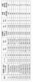
- FIG. 3 is a diagram showing evaluation results of the alkaline storage battery according to the embodiment.
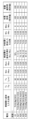
- FIG. 4 is a diagram showing evaluation results of the alkaline storage battery according to the embodiment.
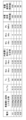
- FIG. 5 is a diagram showing evaluation results of the alkaline storage battery according to the embodiment.
- FIG. 6 is a diagram showing evaluation results of the alkaline storage battery according to the embodiment.
- FIG. 7 is a diagram showing evaluation results of the alkaline storage battery according to the embodiment.
- FIG. 8 is a diagram showing evaluation results of the alkaline storage battery according to the embodiment.
- FIG. 9 is a diagram showing evaluation results of the alkaline storage battery according to the embodiment.
- FIG. 10 is a diagram showing the evaluation results of the alkaline storage battery according to the embodiment.
- the alkaline storage battery according to this embodiment may be referred to as "alkaline storage battery (B)" below.
- the alkaline storage battery (B) includes a positive electrode including a positive electrode mixture layer containing a nickel compound, at least a part of whose surface is coated with a cobalt compound, as a positive electrode active material, and a negative electrode including a negative electrode mixture layer containing a hydrogen storage alloy.
- the positive electrode mixture layer is composed of two surface layers and an inner layer sandwiched between the two surface layers. Each of the surface layer and the inner layer contains the above-mentioned positive electrode active material.
- the thickness Ts of the surface layer is 20 ⁇ m or more.
- the ratio Ts/Tp of the thickness Ts to the thickness Tp of the positive electrode mixture layer is in the range of 0.03 to 0.20.
- the surface layer contains a titanium compound and a magnesium compound.
- the inner layer contains at least one compound of element X selected from the group consisting of Ti, Yb, Y, Nb, and W.
- the ratio Mst/Msc of the mass Mst of titanium contained in the surface layer to the mass Msc of cobalt contained in the surface layer is in the range of 0.04 to 0.60.
- the ratio Msm/Msc of the mass Msm of magnesium contained in the surface layer to the mass Msc is in the range of 0.01 to 0.30.
- the ratio Mix/Mic of the total mass Mix of the at least one element X contained in the inner layer to the mass Mic of cobalt contained in the inner layer is in the range of 0.04 to 0.60.
- the ratio Mim/Mic of the mass Mim of magnesium contained in the inner layer to the mass Mic is 0.001 or less.
- the thickness and/or composition ratio of one surface layer may be the same as or different from the thickness and/or composition ratio of the other surface layer, provided that each surface layer satisfies the above-mentioned conditions regarding thickness and composition ratio for the surface layers.
- a continuous inner layer By using a porous current collector (such as foamed nickel) as the positive electrode current collector, a continuous inner layer can be formed.
- a positive electrode mixture layer is formed on both sides of the positive electrode current collector.
- the positive electrode mixture layer is composed of a first positive electrode mixture layer formed on one side of the positive electrode current collector and a second positive electrode mixture layer formed on the other side of the positive electrode current collector
- the inner layer is composed of a first inner layer formed on one side of the positive electrode current collector and a second inner layer formed on the other side of the positive electrode current collector.
- the thickness Tp of the positive electrode mixture layer is the sum of the thicknesses of the first positive electrode mixture layer and the second positive electrode mixture layer.
- the thickness of the inner layer is the sum of the thicknesses of the first inner layer and the second inner layer.
- the composition of the inner layer is the composition when the first inner layer and the second inner layer are considered as one layer.
- Patent Documents 1 and 2 disclose a technique for adding an additive to the positive electrode.
- oxygen generation at the positive electrode is suppressed by adding an additive to the positive electrode, the surface of the positive electrode becomes a hydrogen atmosphere due to hydrogen released from the hydrogen storage alloy of the negative electrode.
- the cobalt compound on the surface of the positive electrode active material is reduced by hydrogen.
- a part of the reduced cobalt compound dissolves into the electrolyte as ions and migrates to the separator and negative electrode. As a result, the conductivity of the surface of the positive electrode active material decreases, leading to a deterioration in battery characteristics.
- titanium compounds examples include titanium oxide (such as TiO2 ), titanium oxyhydroxide (TiO(OH) 2 ), titanium fluoride ( TiF4 ), etc.
- the titanium compound may be a compound that does not contain any metal element other than titanium.
- magnesium compounds examples include oxide (MgO), hydroxide (Mg(OH) 2 ), halides, various salts, etc.
- halides include fluoride (MgF 2 ), etc.
- salts include carbonate (MgCO 3 ), phosphate (Mg 3 (PO 4 ) 2 ), etc.
- the magnesium compound may be a compound that does not contain any metal element other than magnesium.
- the inner layer contains a compound XC of at least one element X selected from the group consisting of Ti, Yb, Y, Nb, and W.
- a compound XC of at least one element X selected from the group consisting of Ti, Yb, Y, Nb, and W By containing the compound XC in the inner layer, a high effect can be obtained as shown in the examples. This is believed to be because the addition of the compound XC suppresses oxygen generation in the positive electrode.
- the compound XC a compound that can exist relatively stably in the positive electrode mixture can be used. Examples of the compound XC include an oxide of the element X, a hydroxide of the element X, a halide of the element X, and a salt of the element X.
- the compound XC may be a compound shown in the examples.
- a preferred example of the compound XC is a titanium compound.
- the compound XC may be titanium oxide (such as TiO2 ) and/or titanium oxyhydroxide (TiO(OH) 2 ).
- the ratio Mix/Mic of the total mass Mix of at least one element X contained in the inner layer to the mass Mic of cobalt contained in the inner layer is in the range of 0.04 to 0.60.
- the ratio Mix/Mic is in this range, a high effect is obtained as shown in the examples.
- the ratio Mix/Mic is 0.04 or more, and may be 0.10 or more, or 0.30 or more.
- the ratio Mix/Mic is 0.60 or less, and may be 0.30 or less.
- the ratio Mim/Mic of the mass of magnesium Mim contained in the inner layer to the mass of cobalt Mic contained in the inner layer is 0.001 or less. By making the ratio Mim/Mic 0.001 or less, high effects can be obtained as shown in the examples.
- the inner layer is substantially free of magnesium.
- the ratio Mst/Msc of the mass of titanium Mst contained in one surface layer to the mass Msc of cobalt contained in that surface layer is in the range of 0.04 to 0.60.
- the ratio Msm/Msc of the mass of magnesium Msm contained in one surface layer to the mass Msc of cobalt contained in that surface layer is in the range of 0.01 to 0.30.
- the thickness Tp of the positive electrode mixture layer is not particularly limited and is selected according to the application of the battery.
- the thickness Tp is 100 ⁇ m or more, and may be 500 ⁇ m or more.
- the thickness Tp may be 1000 ⁇ m or less, or 500 ⁇ m or less.
- the thickness Ts of one surface layer is 20 ⁇ m or more.
- the total thickness of the two surface layers is 40 ⁇ m or more.
- the ratio Ts/Tp of the thickness Ts to the thickness Tp of the positive electrode mixture layer is in the range of 0.03 to 0.20.
- the ratio Ts/Tp 0.03 or more the effects of hydrogen arriving from the negative electrode can be sufficiently suppressed.
- the surface layer, which has a high proportion of titanium compounds and magnesium compounds, is too thick, it will result in a decrease in discharge capacity.
- the ratio Ts/Tp 0.20 or less the decrease in discharge capacity can be suppressed.
- the ratio Ts/Tp is 0.03 or more, and may be 0.05 or more, or 0.10 or more.
- the ratio Ts/Tp is 0.20 or less, and may be 0.15 or less, or 0.10 or less.
- the surface layer may contain at least one hydroxide of element A selected from the group consisting of Ca and Ba.
- the surface layer may contain at least one hydroxide selected from the group consisting of calcium hydroxide and barium hydroxide.
- the ratio Msa/Msc of the mass Msa of the at least one element A contained in the surface layer to the mass Msc of cobalt contained in the surface layer may be in the range of 0.01 to 0.30 (for example, in the range of 0.05 to 0.20).
- the surface layer may contain a compound of at least one element Z selected from the group consisting of W, Yb, Y, and Nb. With this configuration, as shown in the examples, high effects can be obtained.
- the ratio Msz/Msc of the mass Msz of the at least one element Z contained in the surface layer to the mass Msc of cobalt contained in the surface layer may be in the range of 0.04 to 0.60 (e.g., in the range of 0.10 to 0.30).
- the first manufacturing method (PM1) includes steps (i) and (ii) in this order.
- a first sheet that will be the surface layer and a second sheet that will be the inner layer are formed.
- the first sheet can be formed by preparing a first paste by mixing the components of the surface layer with a dispersion medium, and then applying and drying the first paste in layers.
- the second sheet can be formed by preparing a second paste by mixing the components of the inner layer with a dispersion medium, and then applying and drying the second paste in layers.
- the ratio of the components of the surface layer and the inner layer is determined according to the ratio of the components of each paste. Therefore, the components of each paste and the thickness of each sheet are selected so as to satisfy the above-mentioned conditions.
- the dispersion medium is not particularly limited, and a known dispersion medium (e.g., water) may be used.
- At least the second sheet includes a current collector (e.g., nickel foam). Both the first sheet and the second sheet may include nickel foam.
- each sheet may be formed by applying a paste to a current collector and then drying. Each sheet may be pressed as necessary.
- step (ii) the formed first sheet and second sheet are stacked and pressed together to form a single unit.
- one second sheet is inserted between two first sheets and then pressed together.
- the positive electrode can be formed.
- manufacturing method (PM1) it is preferable to carry out the above steps so that the density of the positive electrode mixture and the distribution of the foamed nickel (current collector) are approximately constant throughout the positive electrode.
- An example of manufacturing method (PM1) will be described in Experiment 1 below.
- step (PM2) Second manufacturing method of the positive electrode (PM2)
- the second manufacturing method (PM2) includes steps (I) and (II) in this order.
- step (I) a positive electrode precursor that becomes a positive electrode is formed.
- the method for forming the positive electrode precursor is not particularly limited, and it can be formed in the same manner as a general positive electrode.
- a paste is prepared by mixing the components of the inner layer and a dispersion medium. Next, the paste is applied to a positive electrode current collector and then dried to form a positive electrode precursor.
- step (II) a liquid containing a compound required for forming a surface layer is applied to the surface of the formed positive electrode precursor, and then dried. At this time, it is possible to adjust the concentration of the compound in the surface layer and the thickness of the surface layer by adjusting the concentration and amount of the liquid. The part that is not penetrated by the compound in the applied liquid becomes the inner layer.
- the positive electrode precursor is pressed as necessary. In this manner, the positive electrode is formed.
- manufacturing method (PM2) the paste and liquid are prepared so that the above-mentioned inner layer and surface layer are formed.
- a paste is prepared by mixing a positive electrode active material, titanium oxide, carboxymethyl cellulose (CMC), and pure water.
- Nickel hydroxide with at least a portion of its surface coated with a cobalt compound is used as the positive electrode active material.
- the paste is applied to a positive electrode current collector and then dried to form a positive electrode precursor.
- a liquid is prepared by dispersing magnesium hydroxide powder in pure water.
- the liquid is then applied to the surface of the positive electrode precursor, which is then dried and the positive electrode precursor is then pressed. In this way, the positive electrode is manufactured.
- the positive electrode of the alkaline storage battery (B) may be formed by impregnating a specific compound into the surface layer of the assembled battery.
- the first manufacturing method (BM1) an alkaline storage battery (B) is manufactured using the above-mentioned positive electrode.
- the first manufacturing method (BM1) may include the manufacturing method (PM1) or manufacturing method (PM2) of the positive electrode.
- the steps other than the manufacturing method of the positive electrode are not particularly limited, and steps used in known manufacturing methods may be used.
- an electrode group consisting of a positive electrode, a negative electrode, and a separator is manufactured.
- the electrode group and the electrolyte are housed in an exterior body to obtain an alkaline storage battery (B).
- the electrode group is a wound electrode group
- the electrode group can be formed by winding the positive electrode, the negative electrode, and the separator so that the separator is disposed between the positive electrode and the negative electrode.
- Second manufacturing method (BM2) In the second manufacturing method (BM2), a surface layer of a positive electrode is formed in a battery.
- the second manufacturing method (PM2) includes steps (1) and (2) in this order.
- step (1) a battery is assembled according to a normal method. However, the entire positive electrode mixture layer is formed with the components and composition ratio of the inner layer described above.
- the method of forming the positive electrode in the battery is not limited, and may be formed by a known method.
- step (2) compounds present in areas other than the positive electrode are moved to the surface of the positive electrode mixture layer, thereby forming a part of the positive electrode mixture layer into a surface layer.
- the area to which the compounds have not moved becomes the inner layer.
- a negative electrode containing Mg and carrying out a specified process it is possible to move Mg in the negative electrode to the surface of the positive electrode mixture layer.
- Mg in the negative electrode it is necessary to carry out the specified process. It is difficult to manufacture an alkaline storage battery (B) using a normal manufacturing method that does not carry out the specified process.
- the positive electrode is made in the following procedure. First, nickel hydroxide powder, titanium oxide powder, carboxymethyl cellulose, and pure water are mixed to prepare a paste. This paste is then applied to a current collector, which is then dried and rolled to obtain the positive electrode.
- the obtained positive electrode, negative electrode, and separator are used to prepare an electrode group. If the electrode group is a wound electrode group, the electrode group can be formed by winding the positive electrode, negative electrode, and separator so that the separator is disposed between the positive electrode and negative electrode.
- a negative electrode containing Mg is used.
- a hydrogen storage alloy containing Mg may be used to form the negative electrode mixture layer.
- a negative electrode mixture layer containing a hydrogen storage alloy and magnesium hydroxide may be used as the negative electrode mixture layer.
- the mass of magnesium hydroxide is 1% of the mass of the hydrogen storage alloy.
- the electrode group and the electrolyte are housed in an exterior body to assemble the battery.
- a predetermined activation step is performed to move Mg (Mg compound) in the negative electrode to the surface of the positive electrode mixture layer.
- Mg Mg compound
- the activation step can be performed by repeating a predetermined cycle. In one cycle, the following (step 1) to (step 5) are performed in order.
- Step 2 The battery is left to stand at 50° C. for 3 hours.
- Step 3 The battery is left to stand at 20° C. for 6 hours.
- Step 4) At 20° C., the battery is charged with an amount of electricity equivalent to 100% of the capacity at a current value of 0.1 It.
- Step 5 The battery is left to stand at 20° C. for 3 hours.
- step 1 Mg in the negative electrode can be dissolved in the electrolyte by increasing the temperature and decreasing the pH of the negative electrode surface due to rapid discharge.
- step 2 Mg ions in the electrolyte can be diffused to the surface layer of the positive electrode.
- step 3 Mg ions diffused to the surface layer can be precipitated as Mg compounds.
- the temperatures in steps 1 and 2 are preferably in the range of 50°C to 80°C.
- the temperature in step 3 is preferably 30°C or lower. The lower the temperature, the easier it is for Mg compounds to precipitate.
- the number of times the cycle is repeated may be changed as appropriate.
- the thickness of the surface layer can be changed depending on the number of times the cycle is repeated. In this manner, a positive electrode including the above-mentioned surface layer and inner layer can be formed. This results in an alkaline storage battery (B).
- the alkaline storage battery (B) contains a nickel compound as a positive electrode active material and a hydrogen storage alloy as a negative electrode active material.
- a nickel-metal hydride storage battery can be called a nickel-metal hydride storage battery.
- An example of the configuration and components of the alkaline storage battery (B) is described below. However, the configuration and components of the alkaline storage battery (B) are not limited to the examples shown below.
- Known components used in alkaline storage batteries e.g., nickel-metal hydride storage batteries
- the alkaline storage battery (B) includes an outer casing, and an electrode group and an alkaline electrolyte housed in the outer casing.
- the electrode group of the wound body is formed by winding a positive electrode, a negative electrode, and a separator so that the separator is disposed between the positive electrode and the negative electrode.
- the electrode group of the laminate is formed by stacking a positive electrode, a negative electrode, and a separator so that the separator is disposed between the positive electrode and the negative electrode.
- the shape of the alkaline storage battery (B) may be cylindrical, rectangular, or button-shaped (including coin-shaped), etc.
- the positive electrode includes a positive electrode mixture layer including a positive electrode active material.
- the positive electrode may include a positive electrode current collector and the positive electrode mixture layer supported by the positive electrode current collector.
- positive electrode collector there are no particular limitations on the positive electrode collector, and any known positive electrode collector may be used.
- positive electrode collectors include porous collectors made of metal (such as nickel or a nickel alloy).
- positive electrode collectors include nickel foam and sintered nickel plate.
- the positive electrode mixture layer contains the positive electrode active material and the above-mentioned compound.
- the positive electrode mixture layer contains other components (conductive material, binder, thickener, etc.) as necessary.
- the positive electrode active material may be particles of a nickel compound at least part of whose surface is coated with a cobalt compound.
- Nickel hydroxide may be used as the nickel compound, but a part of the nickel hydroxide may be changed to nickel oxyhydroxide.
- the nickel compound may be at least one type selected from the group consisting of nickel hydroxide and nickel oxyhydroxide.
- a nickel compound having at least a portion of its surface coated with a cobalt compound may be referred to below as a "Co-coated nickel compound.”
- Particles of Co-coated nickel compounds have traditionally been used as the positive electrode active material in alkaline storage batteries. Therefore, any known positive electrode active material may be used as the positive electrode active material.
- the proportion of the Co-coated nickel compound in the positive electrode mixture layer may be 80% by mass or more (e.g., 90% by mass or more).
- the proportion of the Co compound in the Co-coated nickel compound may be in the range of 2% by mass to 20% by mass (e.g., 3% by mass to 15% by mass).
- the content of the positive electrode active material in the surface layer can be approximately the same as the content of the positive electrode active material in the inner layer.
- the content of the positive electrode active material in the surface layer may be in the range of 0.9 to 1.1 times (e.g., in the range of 0.95 to 1.05 times) the content of the positive electrode active material in the inner layer.
- the method for coating the surface of the nickel compound particles with the Co compound is not particularly limited, and any known method may be used.
- the coating may be performed by applying a dispersion liquid containing the Co compound to the surface of the nickel compound particles and drying the resultant.
- the coating may be performed by a mechanochemical method or the like.
- the conductive material is not particularly limited, and any known conductive material may be used.
- Examples of conductive materials include conductive fibers (metal fibers, etc.), metal particles (nickel particles, cobalt particles, etc.), and conductive carbon materials (graphite, carbon black, etc.). These conductive materials may be used alone or in combination of two or more.
- a conductive cobalt compound (cobalt hydroxide, gamma-type cobalt oxyhydroxide, etc.) may be used as the conductive material.
- the amount of conductive material may be in the range of 0.01 to 20 parts by mass (e.g., 0.1 to 10 parts by mass) per 100 parts by mass of the positive electrode active material.
- the binder is not particularly limited, and known binders used in alkaline storage batteries may be used.
- binders include rubber-like materials such as styrene-butadiene copolymer rubber; polyolefin resins such as polyethylene and polypropylene; fluororesins such as polyvinylidene fluoride; acrylic resins such as ethylene-acrylic acid copolymer and ethylene-methyl acrylate copolymer, and sodium ion crosslinkers thereof.
- One of these binders may be used alone, or two or more may be used in combination.
- the amount of binder may be 7 parts by mass or less, or may be in the range of 0.01 to 5 parts by mass, per 100 parts by mass of the positive electrode active material.
- thickeners examples include carboxymethylcellulose and its modified products (including salts such as sodium salt and ammonium salt), cellulose derivatives such as methylcellulose, saponified polymers having vinyl acetate units such as polyvinyl alcohol, polyalkylene oxides such as polyethylene oxide, etc. These thickeners may be used alone or in combination of two or more.
- the amount of thickener may be 5 parts by mass or less per 100 parts by mass of the positive electrode active material, and may be in the range of 0.01 to 3 parts by mass.
- the positive electrode can be formed by attaching a positive electrode mixture containing a positive electrode active material to a positive electrode current collector.
- the positive electrode mixture is usually used in the form of a paste containing a dispersion medium.
- a positive electrode paste containing a positive electrode active material is first prepared. Next, the positive electrode paste is applied or filled onto a positive electrode current collector, and then dried and rolled. In this manner, a positive electrode can be manufactured that includes a positive electrode current collector and a positive electrode mixture layer supported on the positive electrode current collector.
- the amount of a given element in the positive electrode can be determined from the mass of the material used in manufacturing the positive electrode.
- the amount of a given element in the positive electrode assembled in the battery can be determined using an EPMA (electron probe microanalyzer).
- the positive electrode to be measured is first embedded in an epoxy resin, and cut so that the cross section of the positive electrode appears, to prepare a sample for cross-sectional observation.
- This sample is analyzed by an EPMA (electron probe microanalyzer) at an acceleration voltage of 15 keV and an irradiation current of 5 ⁇ 10 ⁇ 8 A, and a mapping image of Mg is obtained at a magnification of 100 times. The level of the mapping image is adjusted to clarify the shading of Mg.
- the magnification is adjusted to a range of 1000 to 2000 times, and the mapping images of Ni and Co are observed.
- the position of Co coated with a nickel compound (nickel hydroxide, etc.) is identified from the mapping image, and the mass ratios of Ti, Mg, and Co are measured in the range where the coated Co exists.
- the mass ratios of Ti and Mg to Co are obtained from the obtained results.
- the mass ratios of Ti, Yb, Y, Nb, W, Mg, and Co can be measured within the range where the coated Co exists. From the obtained results, the weight ratio of each element to the Co element can be obtained.
- the negative electrode is not particularly limited, except that it contains a negative electrode mixture layer containing a hydrogen storage alloy (negative electrode active material).
- a negative electrode active material As the components other than the negative electrode active material, components of a negative electrode used in a known nickel-metal hydride storage battery may be used.
- the negative electrode may include a negative electrode current collector and a negative electrode mixture layer supported on the negative electrode current collector.
- a negative electrode current collector There is no limitation on the negative electrode current collector, and any known negative electrode current collector may be used.
- Examples of negative electrode current collectors include sheets of porous or non-porous metals (such as stainless steel, nickel, and nickel alloys).
- the negative electrode can be formed by attaching a negative electrode mixture containing a negative electrode active material to a negative electrode current collector.
- the negative electrode mixture is usually used in the form of a paste containing a dispersion medium.
- a negative electrode paste containing a hydrogen storage alloy powder is first prepared. Next, the negative electrode paste is applied to or filled on a negative electrode current collector, and then dried and rolled. In this manner, a negative electrode can be manufactured that includes a negative electrode current collector and a negative electrode mixture layer supported on the negative electrode current collector.
- the negative electrode mixture may contain components other than the negative electrode active material (conductive material, binder, thickener, etc.) as necessary.
- the dispersion medium, conductive material, binder, and thickener may be the same as those exemplified for the positive electrode.
- the alkaline electrolyte may be an aqueous solution containing an alkaline solute.
- the solute include alkali metal hydroxides, specifically lithium hydroxide, potassium hydroxide, sodium hydroxide, etc.
- the solute may be used alone or in combination of two or more kinds.
- the concentration of the solute (specifically, the alkali metal hydroxide) contained in the alkaline electrolyte may be in the range of 2.5 to 13 mol/L (e.g., 3 to 12 mol/L).
- the specific gravity of the alkaline electrolyte may be in the range of 1.1 to 1.6 (e.g., 1.2 to 1.5).
- the alkaline electrolyte preferably contains potassium hydroxide.
- the alkaline electrolyte may contain potassium hydroxide and other alkali metal hydroxides (lithium hydroxide and/or sodium hydroxide).
- the separator is not particularly limited, and a known separator used in an alkaline storage battery (e.g., a nickel-metal hydride storage battery) may be used.
- Examples of the separator form include a microporous membrane, a nonwoven fabric, and a woven fabric.
- the separator can be made of an insulating material.
- Examples of the separator material include polyolefin resins (polyethylene, polypropylene, etc.), fluororesins, and polyamide resins.
- the components other than those described above are not particularly limited, and may be those known for use in alkaline storage batteries (such as nickel-metal hydride storage batteries).
- alkaline storage battery (B) is a cylindrical battery
- an example of the exterior body includes a cylindrical battery case with a bottom, and a sealing body and a gasket that seal the battery case.
- FIG. 1 is a partially exploded perspective view that shows a schematic structure of an alkaline storage battery 10 of the embodiment.
- the alkaline storage battery 10 includes a battery case 4, and an electrode group and an alkaline electrolyte (not shown) housed in the battery case 4.
- the battery case 4 is a cylindrical case with a bottom.
- the electrode group is formed by winding the negative electrode 1, the positive electrode 2, and the separator 3 so that the separator 3 is disposed between the negative electrode 1 and the positive electrode 2.
- the opening of the battery case 4 is sealed by a sealing body 7 and an insulating gasket 8.
- the sealing body 7 includes a positive electrode terminal 5 and a safety valve 6.
- the positive electrode 2 and the sealing body 7 are electrically connected via a positive electrode current collector 9.
- the battery case 4 is electrically connected to the negative electrode 1 and functions as a negative electrode terminal.
- the positive electrode 2 is the above-mentioned positive electrode.
- the positive electrode 2 includes a positive electrode current collector (not shown) and a positive electrode mixture layer 22 held by the positive electrode current collector.
- the positive electrode mixture layer 22 is composed of two surface layers 22s and an inner layer 22i sandwiched between the two surface layers 22s. Each layer satisfies the above-mentioned conditions.
- An alkaline storage battery a positive electrode including a positive electrode mixture layer containing, as a positive electrode active material, a nickel compound at least a portion of whose surface is covered with a cobalt compound; a negative electrode including a negative electrode mixture layer containing a hydrogen storage alloy,
- the positive electrode mixture layer is composed of two surface layers and an inner layer sandwiched between the two surface layers, each of the two surface layers and the inner layer includes the positive electrode active material;
- the thickness Ts of the two surface layers is 20 ⁇ m or more, a ratio Ts/Tp of the thickness Ts to the thickness Tp of the positive electrode mixture layer is in a range of 0.03 to 0.20;
- the two surface layers contain a titanium compound and a magnesium compound, the inner layer contains at least one compound of element X selected from the group consisting of Ti, Yb, Y, Nb, and W; a ratio Mst/Msc of a mass Mst of titanium contained in each of the two surface layers to a mass Msc of
- Experiment 1 In Experiment 1, several types of alkaline storage batteries were produced by changing the positive electrode. Specifically, an alkaline storage battery (battery A1) having a structure similar to that shown in Fig. 1 was produced by the following procedure.
- a positive electrode PA1 was prepared by the method described in the above-mentioned manufacturing method (PM1). Specifically, nickel hydroxide powder was first added to a cobalt sulfate aqueous solution, and the resulting mixture, an ammonia aqueous solution, and a sodium hydroxide aqueous solution were each supplied to a reactor at a predetermined supply rate and mixed under stirring. As a result, the surface of nickel hydroxide powder (100 parts by mass) was coated with cobalt hydroxide (5 parts by mass).
- the coated nickel hydroxide powder was heated in the presence of an NaOH aqueous solution at 90°C to 130°C while supplying air (oxygen), thereby converting the cobalt hydroxide into a conductive cobalt oxide.
- a positive electrode active material nickel hydroxide powder coated with cobalt oxide
- a second paste was prepared by mixing a positive electrode active material, titanium oxide powder, magnesium hydroxide powder, carboxymethyl cellulose (CMC), and pure water. This was applied to a current collector (foamed nickel) and then dried to form a second sheet.
- a first sheet was formed under the same conditions as the method for forming the second sheet, except that magnesium hydroxide was not added.
- one second sheet was placed between two first sheets and pressed to obtain a positive electrode sheet.
- the positive electrode sheet was cut to a specified size to obtain a positive electrode PA1.
- the first sheet portion became the surface layer, and the second sheet portion became the inner layer.
- the first and second sheets were made so that the content of the positive electrode active material, the density of the positive electrode mixture, and the density of the current collector were the same. Furthermore, their thicknesses and pressing were adjusted so that the thickness of the surface layer and the thickness of the positive electrode mixture layer were the values shown in Figure 3.
- the negative electrode paste was then applied to both sides of the negative electrode current collector to form a coating.
- the negative electrode current collector was made of nickel-plated punched iron metal.
- the resulting coating was dried and then pressed together with the negative electrode current collector to form a negative electrode mixture layer.
- the negative electrode mixture layer was formed so that its thickness was substantially the same across the entire negative electrode.
- the sheet consisting of the negative electrode current collector and the negative electrode mixture layer was then cut to a specified size to obtain a negative electrode.
- the wound body and alkaline electrolyte were then placed in a battery case.
- the alkaline electrolyte used had an alkali metal hydroxide concentration of 5.5 mol/L.
- the opening of the battery case was sealed with a gasket and a sealing body.
- the nickel foam porous body (positive electrode current collector) and the sealing body (positive electrode terminal) were electrically connected via a connecting member.
- the negative electrode and the battery case (negative electrode terminal) were electrically connected via a connecting member. In this way, an alkaline storage battery (battery A1) with a rated capacity of 1200 mAh was produced.
- Batteries C1 and C2 were produced in the same manner and under the same conditions as battery A1, except that the compounds contained in the surface layer and the inner layer were changed as shown in Figure 3.
- the mass of Ti in the inner layer was the same as the mass of W.
- the mass of Ti in the inner layer was the same as the mass of Y.
- the charging efficiency of the prepared battery was evaluated by the following method. First, the battery was charged at a current value of 0.1 It for 16 hours in an environment of 20°C, and then left in an environment of 20°C for 3 hours, and then discharged at a current value of 0.2 It in an environment of 20°C until the battery voltage reached 1 V. This charging and discharging was repeated for two cycles, and the discharge capacity E(20) in the second cycle was obtained. In addition, the discharge capacity E(85) in the second cycle was obtained in the same manner, except that the battery temperature during charging was changed to 85°C. The charging efficiency (%) at high temperatures was calculated from the following formula. The higher the charging efficiency, the better the battery characteristics at high temperatures.
- Charging efficiency (%) 100 x E(85) / E(20) (High temperature storage characteristics)
- the high-temperature storage characteristics of the produced battery were evaluated by the following method. First, in an environment of 20° C., the battery was pre-discharged at a current value of 0.2 It until the battery voltage reached 1 V. Next, the battery was charged at a current value of 0.1 It for 16 hours, and then discharged at a current value of 0.2 It until the battery voltage reached 1 V. At this time, the discharge capacity C0 when discharged at a current value of 0.2 It was measured.
- the battery was charged at a current of 0.1 It for 16 hours in an environment of 20°C.
- the battery was then stored in an environment of 85°C for 20 hours, after which it was charged at a current of 0.1 It for 4 hours, and this cycle was repeated for three months.
- Capacity maintenance rate (%) 100 x C1/C0 Part of the manufacturing conditions of the positive electrode and the evaluation results are shown in FIG. 3. In Experiments 1 and 2 in FIG.
- the charging efficiency and capacity retention rate are shown as relative values when the evaluation result of Battery A1 is set to 100.
- the charging efficiency and capacity retention rate are shown as relative values when the evaluation result of Battery A1 is set to 100.
- the charging efficiency and capacity retention rate are shown as relative values when the evaluation result of Battery A1' is set to 100.
- subscripts indicating the ratio of elements and atomic groups in the compound are shown as standard numbers for ease of viewing. For example, “TiO2" in FIG. 3 stands for “TiO 2 " (similarly in FIGS. 4 to 8).
- Battery A1 is an alkaline storage battery (B) according to the present disclosure. Batteries C1 and C2 are comparative examples. As shown in FIG. 3, battery A1 had better battery characteristics at high temperatures than batteries C1 and C2.
- Batteries A1' to A5 and C5 to C6 were produced by varying the conditions for producing the positive electrode as shown in FIG. 3. However, each battery was produced by the method described in the above-mentioned production method (BM2). Batteries A1' to A5 are alkaline storage batteries (B) according to the present disclosure. Batteries C5 to C6 are comparative examples. The produced batteries were evaluated in the same manner as in Experiment 1. As shown in FIG. 3, battery A1 had better battery characteristics at high temperatures than batteries C5 to C6.
- Comparative batteries C7 to C16 were fabricated in the same manner and under the same conditions as those for the battery A1, except that the conditions for fabricating the positive electrode were changed as shown in Figure 3. The fabricated batteries were evaluated in the same manner as in Experiment 1.
- Ms1/Msc is the ratio of the mass Ms1 of element 1 (see Figure 4) contained in the surface layer to the mass Msc of cobalt contained in the surface layer.
- Ms2/Msc is the ratio of the mass Ms2 of element 2 (see Figure 4) contained in the surface layer to the mass Msc of cobalt contained in the surface layer.
- battery A1 had better battery characteristics at high temperatures than batteries C7 to C16.
- Batteries A6 to A11 were produced in the same manner and under the same conditions as those for the production of battery A1, except that the conditions for producing the positive electrode were changed as shown in Figure 5.
- Batteries A6 to A11 are alkaline storage batteries (B) according to the present disclosure. The produced batteries were evaluated in the same manner as in Experiment 1. As shown in Figure 5, all of the batteries according to the present disclosure had excellent battery characteristics at high temperatures.
- Batteries A18 to A26 according to the present disclosure and comparative batteries C21 to C23 were fabricated in the same manner and under the same conditions as those for the fabrication of battery A1, except that the fabrication conditions for the positive electrode were changed as shown in Figure 7.
- the fabricated batteries were evaluated in the same manner as in Experiment 1. As shown in Figure 7, the batteries according to the present disclosure had better battery characteristics at high temperatures than the comparative batteries.
- alkaline storage batteries e.g., nickel-metal hydride storage batteries.
Landscapes
- Chemical & Material Sciences (AREA)
- Chemical Kinetics & Catalysis (AREA)
- Electrochemistry (AREA)
- General Chemical & Material Sciences (AREA)
- Engineering & Computer Science (AREA)
- Manufacturing & Machinery (AREA)
- Inorganic Chemistry (AREA)
- Battery Electrode And Active Subsutance (AREA)
Priority Applications (2)
| Application Number | Priority Date | Filing Date | Title |
|---|---|---|---|
| CN202480021557.5A CN120883388A (zh) | 2023-03-28 | 2024-02-28 | 碱性蓄电池 |
| JP2025510021A JPWO2024202852A1 (https=) | 2023-03-28 | 2024-02-28 |
Applications Claiming Priority (2)
| Application Number | Priority Date | Filing Date | Title |
|---|---|---|---|
| JP2023051844 | 2023-03-28 | ||
| JP2023-051844 | 2023-03-28 |
Publications (1)
| Publication Number | Publication Date |
|---|---|
| WO2024202852A1 true WO2024202852A1 (ja) | 2024-10-03 |
Family
ID=92905426
Family Applications (1)
| Application Number | Title | Priority Date | Filing Date |
|---|---|---|---|
| PCT/JP2024/007243 Ceased WO2024202852A1 (ja) | 2023-03-28 | 2024-02-28 | アルカリ蓄電池 |
Country Status (3)
| Country | Link |
|---|---|
| JP (1) | JPWO2024202852A1 (https=) |
| CN (1) | CN120883388A (https=) |
| WO (1) | WO2024202852A1 (https=) |
Citations (4)
| Publication number | Priority date | Publication date | Assignee | Title |
|---|---|---|---|---|
| WO2013132818A1 (ja) * | 2012-03-05 | 2013-09-12 | パナソニック株式会社 | アルカリ蓄電池用正極およびそれを用いたアルカリ蓄電池 |
| JP2015130249A (ja) * | 2014-01-06 | 2015-07-16 | パナソニックIpマネジメント株式会社 | アルカリ蓄電池用正極およびそれを用いたアルカリ蓄電池 |
| JP2020043010A (ja) * | 2018-09-12 | 2020-03-19 | Fdk株式会社 | アルカリ二次電池用の正極及びこの正極を含むアルカリ二次電池 |
| WO2021220627A1 (ja) * | 2020-05-01 | 2021-11-04 | 日本碍子株式会社 | ニッケル亜鉛二次電池 |
-
2024
- 2024-02-28 JP JP2025510021A patent/JPWO2024202852A1/ja active Pending
- 2024-02-28 WO PCT/JP2024/007243 patent/WO2024202852A1/ja not_active Ceased
- 2024-02-28 CN CN202480021557.5A patent/CN120883388A/zh active Pending
Patent Citations (4)
| Publication number | Priority date | Publication date | Assignee | Title |
|---|---|---|---|---|
| WO2013132818A1 (ja) * | 2012-03-05 | 2013-09-12 | パナソニック株式会社 | アルカリ蓄電池用正極およびそれを用いたアルカリ蓄電池 |
| JP2015130249A (ja) * | 2014-01-06 | 2015-07-16 | パナソニックIpマネジメント株式会社 | アルカリ蓄電池用正極およびそれを用いたアルカリ蓄電池 |
| JP2020043010A (ja) * | 2018-09-12 | 2020-03-19 | Fdk株式会社 | アルカリ二次電池用の正極及びこの正極を含むアルカリ二次電池 |
| WO2021220627A1 (ja) * | 2020-05-01 | 2021-11-04 | 日本碍子株式会社 | ニッケル亜鉛二次電池 |
Also Published As
| Publication number | Publication date |
|---|---|
| CN120883388A (zh) | 2025-10-31 |
| JPWO2024202852A1 (https=) | 2024-10-03 |
Similar Documents
| Publication | Publication Date | Title |
|---|---|---|
| US20230290942A1 (en) | Solid Phase Synthesis Method of Positive Electrode Active Material of Nickel-Rich Lithium Composite Transition Metal Oxide in a Form of a Single Particle, Positive Electrode Active Material of Nickel-Rich Lithium Composite Transition Metal Oxide in a Form of a Single Particle Formed Therefrom, Positive Electrode and Lithium Secondary Battery Containing the Same | |
| US10326160B2 (en) | Cathode and lithium battery using the same | |
| JP3191752B2 (ja) | ニッケル−水素二次電池およびその電極の製造方法 | |
| CN113597409B (zh) | 二次电池用的正极活性物质和二次电池 | |
| CN108206277A (zh) | 改性高镍三元正极材料及其制备方法、锂离子电池 | |
| JP7797448B2 (ja) | 亜鉛電池 | |
| WO2000060688A1 (fr) | Batterie nickel-hydrogene haute temperature et son procede de fabrication | |
| US6348284B1 (en) | Non-sintered nickel electrode for a secondary electro-chemical cell having an alkaline electrolyte | |
| CN106463786A (zh) | 镍氢二次电池 | |
| JP7807577B2 (ja) | 亜鉛二次電池用負極の製造方法 | |
| US5989746A (en) | Pasted nickel electrode | |
| JP7724274B2 (ja) | ニッケル亜鉛電池 | |
| US6447699B1 (en) | Electrode conductive material | |
| EP3413381B1 (en) | Non-sintered positive electrode for alkaline secondary battery and alkaline secondary battery including non-sintered positive electrode | |
| WO2024202852A1 (ja) | アルカリ蓄電池 | |
| JP7166705B2 (ja) | 亜鉛電池用負極の製造方法及び亜鉛電池の製造方法 | |
| CN115036509A (zh) | 一种固态电池用正极材料及其制备方法与应用 | |
| JP2022081421A (ja) | 亜鉛電池用負極体及び亜鉛電池 | |
| CN119092658B (zh) | 正极活性材料、镍电极和碱性蓄电池 | |
| JP2021185560A (ja) | 亜鉛電池用負極及び亜鉛電池 | |
| JP3352338B2 (ja) | アルカリ蓄電池の製造方法 | |
| JP2020187862A (ja) | 水素空気二次電池用の水素吸蔵合金負極、及び、この水素吸蔵合金負極を含む水素空気二次電池 | |
| CN119156728A (zh) | 碱蓄电池 | |
| JP2024000748A (ja) | アルカリ蓄電池用正極板、及びアルカリ蓄電池 | |
| KR20250045778A (ko) | 리튬 이차 전지용 양극 활물질 및 이의 제조 방법 |
Legal Events
| Date | Code | Title | Description |
|---|---|---|---|
| 121 | Ep: the epo has been informed by wipo that ep was designated in this application |
Ref document number: 24778992 Country of ref document: EP Kind code of ref document: A1 |
|
| ENP | Entry into the national phase |
Ref document number: 2025510021 Country of ref document: JP Kind code of ref document: A |
|
| WWE | Wipo information: entry into national phase |
Ref document number: 2025510021 Country of ref document: JP |
|
| WWE | Wipo information: entry into national phase |
Ref document number: 202480021557.5 Country of ref document: CN |
|
| NENP | Non-entry into the national phase |
Ref country code: DE |
|
| WWP | Wipo information: published in national office |
Ref document number: 202480021557.5 Country of ref document: CN |
|
| 122 | Ep: pct application non-entry in european phase |
Ref document number: 24778992 Country of ref document: EP Kind code of ref document: A1 |