WO2024202822A1 - 車両の空力装置 - Google Patents
車両の空力装置 Download PDFInfo
- Publication number
- WO2024202822A1 WO2024202822A1 PCT/JP2024/007037 JP2024007037W WO2024202822A1 WO 2024202822 A1 WO2024202822 A1 WO 2024202822A1 JP 2024007037 W JP2024007037 W JP 2024007037W WO 2024202822 A1 WO2024202822 A1 WO 2024202822A1
- Authority
- WO
- WIPO (PCT)
- Prior art keywords
- vehicle
- fin
- rear end
- slit portion
- vehicle body
- Prior art date
- Legal status (The legal status is an assumption and is not a legal conclusion. Google has not performed a legal analysis and makes no representation as to the accuracy of the status listed.)
- Ceased
Links
Images



Classifications
-
- B—PERFORMING OPERATIONS; TRANSPORTING
- B62—LAND VEHICLES FOR TRAVELLING OTHERWISE THAN ON RAILS
- B62D—MOTOR VEHICLES; TRAILERS
- B62D37/00—Stabilising vehicle bodies without controlling suspension arrangements
- B62D37/02—Stabilising vehicle bodies without controlling suspension arrangements by aerodynamic means
-
- Y—GENERAL TAGGING OF NEW TECHNOLOGICAL DEVELOPMENTS; GENERAL TAGGING OF CROSS-SECTIONAL TECHNOLOGIES SPANNING OVER SEVERAL SECTIONS OF THE IPC; TECHNICAL SUBJECTS COVERED BY FORMER USPC CROSS-REFERENCE ART COLLECTIONS [XRACs] AND DIGESTS
- Y02—TECHNOLOGIES OR APPLICATIONS FOR MITIGATION OR ADAPTATION AGAINST CLIMATE CHANGE
- Y02T—CLIMATE CHANGE MITIGATION TECHNOLOGIES RELATED TO TRANSPORTATION
- Y02T10/00—Road transport of goods or passengers
- Y02T10/80—Technologies aiming to reduce greenhouse gasses emissions common to all road transportation technologies
- Y02T10/82—Elements for improving aerodynamics
Definitions
- the present invention relates to an aerodynamic device for a vehicle.
- Patent Document 1 proposes an aerodynamic device provided at the corner between the side and rear portions of the rear of a vehicle body, which includes an intake port provided on the side portion, an exhaust port provided on the rear portion, and a cross-flow fan that exhausts air sucked in through the intake port through the exhaust port.
- an aerodynamic device is provided in which a pair of side fins are provided that extend in the vertical direction along the upper rear end of the side surface of the vehicle body and protrude rearward of the vehicle, and that straighten the airflow with the side fins.
- the present invention has been devised in consideration of the above-mentioned circumstances, and has an object to provide an aerodynamic device for a vehicle that is advantageous in reducing air resistance while the vehicle is traveling, without requiring a large fore-and-aft dimension for the side fins.
- one embodiment of the present invention is an aerodynamic device for a vehicle having a pair of side fins that extend vertically along the upper rear end of the side of the vehicle body and protrude to the rear of the vehicle, the outer surfaces of the side fins are formed so as to displace inward in the vehicle width direction as they reach the rear of the vehicle, and the side fins are provided with slits that extend vertically and connect the outer and inner sides of the side fins in the vehicle width direction.
- the vehicle when the vehicle is traveling, air flows from the inside of the side fin in the vehicle width direction toward the outside of the vehicle width direction through the slit portion, which is advantageous in reducing air resistance by suppressing the air flow that is drawn in from the upper rear end of the side of the vehicle body toward the inside of the vehicle width direction when the vehicle is traveling.
- the outer surface of the side fin is formed so as to be displaced inward in the vehicle width direction as it reaches the rear of the vehicle, when the vehicle is moving, the air flow moving along the side of the vehicle body toward the rear of the vehicle does not interfere with the slit portion and the air flow is prevented from entering the slit portion, which is advantageous for ensuring the air flow ejecting from the slit portion and for reducing air resistance. This is advantageous in reducing air resistance without requiring a large longitudinal dimension for the side fins.
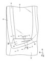
- FIG. 1 is a perspective view of an aerodynamic device according to a first embodiment, as viewed from the rear of a vehicle. 1, (B) is a cross-sectional view taken along line BB in FIG. 1, and (C) is a cross-sectional view taken along line CC in FIG.
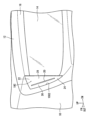
- FIG. 11 is a perspective view of an aerodynamic device according to a second embodiment, as viewed from the rear of a vehicle.
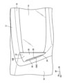
- FIG. 11 is a perspective view of an aerodynamic device according to a third embodiment, as viewed from the rear of the vehicle.
- FIG. 13 is a perspective view of an aerodynamic device according to a fourth embodiment, as viewed from the rear of the vehicle.
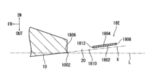
- FIG. 13 is a perspective view of an aerodynamic device according to a fifth embodiment, as viewed from the rear of the vehicle. This is a cross-sectional view taken along line D-D in Figure 6.
- the symbol FR indicates the front of the vehicle
- the symbol UP indicates the upper side of the vehicle
- the symbol IN indicates the inner side in the vehicle width direction
- the symbol OUT indicates the outer side in the vehicle width direction.
- the upper rear portion of the vehicle is configured to include rear portions of vehicle body side surfaces 10 on both sides in the vehicle width direction, the rear portion of a roof panel 12 , and a rear window 14 .
- a rear spoiler 16 is provided on the roof panel 12 above the rear window 14, and a pair of side fins 18A are provided on each end in the vehicle width direction of the rear spoiler 16.
- the pair of side fins 18A constitute an aerodynamic device for the vehicle.
- the rear spoiler 16 extends in the vehicle width direction along the rear end of the roof panel 12 that forms the upper surface of the vehicle body, and protrudes toward the rear of the vehicle.
- the side fin 18A in the first embodiment extends in the vertical direction along the upper rear end 1002 of the vehicle body side surface 10 and protrudes toward the rear of the vehicle, and the upper end of the side fin 18A is connected to the end of the rear spoiler 16.
- the side fin 18A has an outer surface 1802 facing outward in the vehicle width direction and an inner surface 1804 facing inward in the vehicle width direction.
- the side fin 18A also has a leading edge 1806 located at the upper rear end 1002 of the vehicle body side surface 10 and a trailing edge 1808 away from the upper rear end 1002 of the vehicle body side surface 10.
- the side fins 18A are formed so as to be displaced inward in the vehicle width direction as they approach the rear of the vehicle.
- the outer surfaces 1802 of the side fins 18A are formed so as to be displaced inward in the vehicle width direction as they approach the rear of the vehicle.
- the symbol L indicates an imaginary line extending in the longitudinal direction of the vehicle.
- the side fin 18A is provided with a slit portion 20 that extends in the vertical direction and communicates with the outer side and the inner side of the side fin 18A in the vehicle width direction.
- the slit portion 20 is provided between the leading edge 1806 and the trailing edge 1808 .
- the slit portion 20 extends in a substantially straight line with an inclination such that its upper end is located further forward of the vehicle than its lower end.
- the upper end of the slit portion 20 is located at a position spaced below the upper end of the side fin 18A, and the lower end of the slit portion 20 is located at a position spaced above the lower end of the side fin 18A.
- the portion of the side fin 18A located above the slit portion 20 is formed as a single upper fin portion 22 as shown in FIG. 2(A), and the portion of the side fin 18A located below the slit portion 20 is formed as a single lower fin portion 24 as shown in FIG. 2(C).
- the side fin 18A has a front fin portion 26 located in front of the slit portion 20 and a rear fin portion 28 located behind the slit portion 20.
- the rear end 2602 of the front fin portion 26 is located further inward in the vehicle width direction than the front end 2802 of the rear fin portion 28 , and the slit portion 20 is provided between the rear end 2602 of the front fin portion 26 and the front end 2802 of the rear fin portion 28 .
- a rear end 2602 of the front fin portion 26 and a front end 2802 of the rear fin portion 28 overlap each other in the vehicle width direction.
- a pair of side fins 18A extending in the vertical direction along the upper rear end 1002 of the vehicle body side surface 10 and protruding toward the rear of the vehicle are provided with a slit portion 20 extending in the vertical direction and connecting the outer and inner sides of the side fins 18A in the vehicle width direction. Therefore, when the vehicle is traveling, air flows from the inside of the side fin 18A in the vehicle width direction toward the outside of the vehicle width direction through the slit portion 20, thereby suppressing the air flow that is drawn inward in the vehicle width direction from the upper rear end 1002 of the vehicle body side surface 10 when the vehicle is traveling, thereby reducing the negative pressure applied to the rear surface of the vehicle body, which is advantageous in reducing air resistance.
- the outer surface 1802 of the side fin 18A is formed so as to be displaced inward in the vehicle width direction as it reaches the rear of the vehicle, when the vehicle is traveling, the air flow moving toward the rear of the vehicle along the side surface 10 of the vehicle body does not interfere with the slit portion 20, and the air flow is prevented from entering the slit portion 20, which is advantageous for ensuring the air flow ejected from the slit portion 20, reducing the negative pressure applied to the rear surface of the vehicle body, and is advantageous for reducing air resistance. This is advantageous in reducing air resistance without requiring a large longitudinal dimension for the side fins 18A.
- the slit portion 20 extends vertically between the leading edge 1806 and the rear edge 1808 of the side fin 18A, the rear end 2602 of the front fin portion 26 of the side fin 18A is positioned more inward in the vehicle width direction than the front end 2802 of the rear fin portion 28, and the slit portion 20 is provided between the rear end 2602 of the front fin portion 26 and the front end 2802 of the rear fin portion 28.
- the air flow is ejected diagonally forward from the slit portion 20, it is more advantageous in suppressing the air flow that is drawn inward in the vehicle width direction from the upper rear end 1002 of the vehicle body side surface 10 when the vehicle is moving, and it is more advantageous in reducing the negative pressure applied to the rear surface of the vehicle body and reducing air resistance.
- the rear end 2602 of the front fin portion 26 and the front end 2802 of the rear fin portion 28 overlap in the vehicle width direction, which is advantageous in more reliably ejecting airflow diagonally forward from the slit portion 20. This is therefore even more advantageous in suppressing the air flow that is drawn inward in the vehicle width direction from the upper rear end 1002 of the vehicle side surface 10 when the vehicle is moving, and is even more advantageous in reducing the negative pressure applied to the rear surface of the vehicle body and reducing air resistance.
- the vehicle has a rear spoiler 16 that extends in the vehicle width direction along the rear end of the upper surface of the vehicle body and protrudes toward the rear of the vehicle, and the upper ends of a pair of side fins 18A are connected to both ends of the rear spoiler 16, respectively.
- the same parts and members as those in the first embodiment are denoted by the same reference numerals, and their description will be omitted or simplified, and the description will focus on the parts that are different from the first embodiment.
- the extending direction of the slit portion 20 is different from that of the first embodiment, but other points are similar to those of the first embodiment.
- the slit portion 20 extends substantially linearly in the vertical direction.
- the direction of the band-shaped air flow ejected from the slit portion 20 is approximately perpendicular to the direction of the air flow flowing along the side of the vehicle along the vehicle body side surface 10, so that the air flow can be controlled uniformly in the vertical direction of the vehicle, which is even more advantageous in suppressing the air flow that is sucked in from the upper rear end 1002 of the vehicle body side surface 10 toward the inside in the vehicle width direction, thereby reducing the negative pressure applied to the rear surface of the vehicle body and reducing air resistance.
- the extending direction of the slit portion 20 is different from that of the first embodiment, as in the second embodiment, but the other parts are the same as those of the first embodiment.
- the slit portion 20 extends in a substantially straight line substantially parallel to the upper rear end 1002 of the vehicle body side surface 10 . Therefore, not only can the same effects as in the first embodiment be obtained, but the second embodiment is also advantageous in ensuring a larger overall length of the slit portion 20 .
- the side fin 18D of the fourth embodiment is a modified example of the third embodiment, in which a slit portion 20 extending substantially linearly and substantially parallel to the upper rear end 1002 of the vehicle body side surface 10 is provided adjacent to the upper rear end 1002 of the vehicle body side surface 10. Therefore, the slit portion 20 can be positioned further forward of the side fin 18D than in the third embodiment. At locations further forward of the side fins 18D, when the vehicle is traveling, the circulating air flow that develops in the space enclosed by the rear spoiler 16 and the pair of side fins 18D strongly interferes, resulting in a region with higher pressure than the region behind the side fins 18D.
- the pressure difference between the outside of the side fin 18D and the inside of the side fin 18D becomes larger, which is advantageous for ejecting more air through the slit portion 20 from the space surrounded by the rear spoiler 16 and the pair of side fins 18D, thereby reducing the negative pressure applied to the rear surface of the vehicle body, and is even more advantageous for reducing air resistance.
- the side fin 18E of the fifth embodiment differs from the first embodiment in that the slit portion 20 is not formed between the leading edge 1806 and the trailing edge 1808, but is provided between the upper rear end 1002 of the vehicle body side surface 10 and the side fin 18E. That is, a notch 1810 that is open forward is provided in a vertically intermediate portion of the leading edge 1806 of the side fin 18E, toward the lower portion.
- the side fin 18E has a notch upper end 1811 that extends approximately linearly in the front-to-rear direction and forms the upper end of the notch 1810, and a notch rear end 1812 that extends approximately linearly in the up-down direction and forms the rear end of the notch 1810.
- the cutout rear end 1812 and the upper rear end 1002 of the vehicle body side surface 10 form a slit portion 20 extending vertically.
- the notch rear end 1812 of the side fin 18E forming the slit portion 20 is located inward in the vehicle width direction from an extension line X that extends rearward from the upper rear end 1002 of the vehicle body side surface 10. Therefore, in the fifth embodiment, the side fin 18E comprises an upper fin portion 22 located above the slit portion 20, a rear fin portion 28 located behind the slit portion 20, and a lower fin portion 24 located below the slit portion 20.
- a slit portion 20 is formed by the cutout rear end 1812 of the side fin 18E and the upper rear end 1002 of the vehicle body side surface 10, and the cutout rear end 1812 is located inward in the vehicle width direction from the extension line X extending rearward from the upper rear end 1002 of the vehicle body side surface 10. Therefore, by providing the slit portion 20 adjacent to the upper rear end 1002 of the vehicle body side surface 10, the slit portion 20 can be positioned at the forward-most location of the side fin 18E.
- the multiple slit portions 20 may be spaced apart in the front-to-back direction, or the multiple slit portions 20 may be spaced apart in the up-down direction, or the multiple slit portions 20 may be arranged in a staggered pattern, and the arrangement structure of the multiple slit portions 20 is arbitrary.
- Vehicle body side 1002 Upper rear end 12 Roof panel 14 Rear window 16 Rear spoiler 18A, 18B, 18C, 18D, 18E Side fin 1802 Outer surface 1804 Inner surface 1806 Front edge 1808 Rear edge 1810 Cutout 1811 Cutout upper end 1812 Cutout rear end 20 Slit portion 22 Upper fin portion 24 Lower fin portion 26 Front fin portion 2602 Rear end 28 Rear fin portion 2802 Front end L Imaginary line X extending in the vehicle fore-and-aft direction Extension line
Landscapes
- Engineering & Computer Science (AREA)
- Physics & Mathematics (AREA)
- Fluid Mechanics (AREA)
- Chemical & Material Sciences (AREA)
- Combustion & Propulsion (AREA)
- Transportation (AREA)
- Mechanical Engineering (AREA)
- Body Structure For Vehicles (AREA)
Priority Applications (1)
| Application Number | Priority Date | Filing Date | Title |
|---|---|---|---|
| JP2025510007A JPWO2024202822A1 (https=) | 2023-03-29 | 2024-02-27 |
Applications Claiming Priority (2)
| Application Number | Priority Date | Filing Date | Title |
|---|---|---|---|
| JP2023-053157 | 2023-03-29 | ||
| JP2023053157 | 2023-03-29 |
Publications (1)
| Publication Number | Publication Date |
|---|---|
| WO2024202822A1 true WO2024202822A1 (ja) | 2024-10-03 |
Family
ID=92905181
Family Applications (1)
| Application Number | Title | Priority Date | Filing Date |
|---|---|---|---|
| PCT/JP2024/007037 Ceased WO2024202822A1 (ja) | 2023-03-29 | 2024-02-27 | 車両の空力装置 |
Country Status (2)
| Country | Link |
|---|---|
| JP (1) | JPWO2024202822A1 (https=) |
| WO (1) | WO2024202822A1 (https=) |
Citations (3)
| Publication number | Priority date | Publication date | Assignee | Title |
|---|---|---|---|---|
| JPS63172785U (https=) * | 1987-05-01 | 1988-11-09 | ||
| DE102018004148A1 (de) * | 2018-05-24 | 2018-11-29 | Daimler Ag | Anordnung einer Luftleiteinrichtung an einem Aufbau für ein Fahrzeug, insbesondere für ein Nutzfahrzeug, sowie Fahrzeug mit einer solchen Anordnung |
| US20200369331A1 (en) * | 2017-12-27 | 2020-11-26 | Magna Exteriors Inc. | Applique with deployable aerodynamic surface |
-
2024
- 2024-02-27 JP JP2025510007A patent/JPWO2024202822A1/ja active Pending
- 2024-02-27 WO PCT/JP2024/007037 patent/WO2024202822A1/ja not_active Ceased
Patent Citations (3)
| Publication number | Priority date | Publication date | Assignee | Title |
|---|---|---|---|---|
| JPS63172785U (https=) * | 1987-05-01 | 1988-11-09 | ||
| US20200369331A1 (en) * | 2017-12-27 | 2020-11-26 | Magna Exteriors Inc. | Applique with deployable aerodynamic surface |
| DE102018004148A1 (de) * | 2018-05-24 | 2018-11-29 | Daimler Ag | Anordnung einer Luftleiteinrichtung an einem Aufbau für ein Fahrzeug, insbesondere für ein Nutzfahrzeug, sowie Fahrzeug mit einer solchen Anordnung |
Also Published As
| Publication number | Publication date |
|---|---|
| JPWO2024202822A1 (https=) | 2024-10-03 |
Similar Documents
| Publication | Publication Date | Title |
|---|---|---|
| CN104203731B (zh) | 具有车底护罩的机动车 | |
| US9738331B2 (en) | Vehicle lower portion structure | |
| JP6477762B2 (ja) | 車両の前部車体構造 | |
| US20020153746A1 (en) | Solid state drag reducing vehicle grille | |
| CN109955914B (zh) | 挡泥板衬里结构 | |
| CN110300696A (zh) | 车辆的空气阻力降低装置 | |
| CN106005060A (zh) | 车辆用空气动力结构 | |
| CN104870298A (zh) | 车身后部结构 | |
| JPH0725369A (ja) | 車両の後部車体構造 | |
| CN110654227B (zh) | 车辆的前部结构 | |
| JPH1170887A (ja) | 車両のユニットを通気するための装置 | |
| JPS6361687A (ja) | 自動車のフロントサイド部構造 | |
| WO2024202822A1 (ja) | 車両の空力装置 | |
| US20180178860A1 (en) | Vehicle side structure of pickup truck | |
| JP2020032742A (ja) | 車両のダクト構造 | |
| CN102695632B (zh) | 保险杠组件 | |
| US20180362102A1 (en) | Vehicle understructure | |
| US10683040B2 (en) | Water separation in wheel houses | |
| US12420627B2 (en) | Vehicle | |
| JP7124559B2 (ja) | 車両のダクト構造 | |
| CN110893765A (zh) | 车辆前部构造 | |
| JP7830060B2 (ja) | 空気抵抗低減装置 | |
| JP3269197B2 (ja) | 自動車のアンダーフロア構造 | |
| US11794824B2 (en) | Vehicle air guide path structure and air guide path forming member | |
| CN117087776A (zh) | 一种前翼组件 |
Legal Events
| Date | Code | Title | Description |
|---|---|---|---|
| 121 | Ep: the epo has been informed by wipo that ep was designated in this application |
Ref document number: 24778963 Country of ref document: EP Kind code of ref document: A1 |
|
| DPE1 | Request for preliminary examination filed after expiration of 19th month from priority date (pct application filed from 20040101) | ||
| WWE | Wipo information: entry into national phase |
Ref document number: 2025510007 Country of ref document: JP |
|
| NENP | Non-entry into the national phase |
Ref country code: DE |
|
| 122 | Ep: pct application non-entry in european phase |
Ref document number: 24778963 Country of ref document: EP Kind code of ref document: A1 |