WO2024202230A1 - 切削インサート、切削工具及び切削加工物の製造方法 - Google Patents
切削インサート、切削工具及び切削加工物の製造方法 Download PDFInfo
- Publication number
- WO2024202230A1 WO2024202230A1 PCT/JP2023/042173 JP2023042173W WO2024202230A1 WO 2024202230 A1 WO2024202230 A1 WO 2024202230A1 JP 2023042173 W JP2023042173 W JP 2023042173W WO 2024202230 A1 WO2024202230 A1 WO 2024202230A1
- Authority
- WO
- WIPO (PCT)
- Prior art keywords
- region
- flow path
- rear end
- cutting
- tip
- Prior art date
- Legal status (The legal status is an assumption and is not a legal conclusion. Google has not performed a legal analysis and makes no representation as to the accuracy of the status listed.)
- Ceased
Links
Images





Classifications
-
- B—PERFORMING OPERATIONS; TRANSPORTING
- B23—MACHINE TOOLS; METAL-WORKING NOT OTHERWISE PROVIDED FOR
- B23B—TURNING; BORING
- B23B27/00—Tools for turning or boring machines; Tools of a similar kind in general; Accessories therefor
- B23B27/10—Cutting tools with special provision for cooling
-
- B—PERFORMING OPERATIONS; TRANSPORTING
- B23—MACHINE TOOLS; METAL-WORKING NOT OTHERWISE PROVIDED FOR
- B23B—TURNING; BORING
- B23B29/00—Holders for non-rotary cutting tools; Boring bars or boring heads; Accessories for tool holders
- B23B29/04—Tool holders for a single cutting tool
- B23B29/043—Tool holders for a single cutting tool with cutting-off, grooving or profile cutting tools, i.e. blade- or disc-like main cutting parts
Definitions
- This aspect relates to a method for manufacturing cutting inserts, cutting tools, and machined products.
- Patent Document 1 As cutting inserts for cutting tools used when cutting workpieces, for example, the cutting inserts described in JP 2022-046273 A (Patent Document 1) and JP 2001-198708 A (Patent Document 2) are known.
- the cutting inserts described in Patent Documents 1 and 2 have internal flow paths through which coolant flows to cool the cutting insert.
- a cutting insert is a cutting insert extending from the tip to the rear end along a reference axis, and has an upper surface having a rake surface region, a lower surface facing the opposite side to the upper surface, a tip surface located on the tip side and having a clearance surface region, a rear end surface located on the rear end side, and a first flow path extending from the tip surface to the rear end surface, the first flow path having a first region extending from the tip surface toward the rear end side and having an inner diameter that increases toward the rear end side, and a second region extending from the rear end surface toward the tip side and having an inner diameter that increases toward the tip side.
- FIG. 1 is a perspective view illustrating a cutting insert according to an embodiment of the present disclosure.
- FIG. 2 is a perspective plan view of the cutting insert shown in FIG. 1 .
- 3 is a plan view of the cutting insert shown in FIG. 2 as viewed from an A1 direction.
- FIG. 3 is a plan view of the cutting insert shown in FIG. 2 as viewed from the A2 direction.
- FIG. 1 is a perspective view of a cutting tool according to an embodiment of the present disclosure.
- FIG. 6 is an enlarged view of a region B1 shown in FIG. 5 .
- FIG. 7 is a plan view of the cutting tool holder shown in FIG. 6 .
- FIG. 6 is a transparent plan view of the cutting tool shown in FIG. 5 .
- 9 is a plan view of the cutting tool shown in FIG.
- FIG. 2 is a diagram illustrating a step in a method for manufacturing a machined product according to an embodiment of the present disclosure.
- FIG. 2 is a diagram illustrating a step in a method for manufacturing a machined product according to an embodiment of the present disclosure.
- FIG. 2 is a diagram illustrating a step in a method for manufacturing a machined product according to an embodiment of the present disclosure.
- insert 1 a non-limiting embodiment of the cutting insert 1 (hereinafter referred to as insert 1), a cutting tool holder 101 (hereinafter referred to as holder 101), a cutting tool 201, and a manufacturing method of a machined product 303 according to the present disclosure
- insert 1 a non-limiting embodiment of the cutting insert 1
- holder 101 a cutting tool holder 101
- cutting tool 201 a cutting tool 201
- a manufacturing method of a machined product 303 a manufacturing method of a machined product 303 according to the present disclosure
- the insert 1 of this embodiment has a first surface 3 (upper surface 3), a second surface 5 (lower surface 5) facing opposite the first surface 3, i.e., located opposite the first surface 3, and a third surface 7 (side surface 7) located between the first surface 3 and the second surface 5.
- the first surface 3, the second surface 5, and the third surface 7 may be polygonal. Furthermore, the first surface 3, the second surface 5, and the third surface 7 each have multiple corners and multiple sides.
- the insert 1 has a prismatic shape extending from the first end 1a to the second end 1b along the reference axis O1, and more specifically, has a generally convex shape.
- the reference axis O1 is an axis that passes through the center of the insert 1.
- the first end 1a will be referred to as the leading end 1a
- the second end 1b will be referred to as the trailing end 1b.
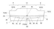
- FIG. 2 is a plan view seen through the insert 1 shown in FIG. 1. More specifically, it is a plan view seen through the internal flow path of the insert 1. Also, FIG. 3 is a plan view seen through the insert 1 shown in FIG. 2 from the A1 direction. FIG. 4 is a plan view seen through the insert 1 shown in FIG. 2 from the A2 direction.
- the insert 1 may also have a cutting edge portion 9 located on the side of the tip 1a, and a clamp portion 11 to which the cutting edge portion 9 is attached.
- the cutting edge portion 9 is the portion where the cutting edge 13 is located.
- the cutting edge portion 9 may be located in two places, on the side of the tip 1a and on the side of the rear end 1b.
- the clamp portion 11 is a portion that abuts against the holder 101 in the up-down direction, and the insert 1 is fixed to the holder 101 by clamping the clamp portion 11 to the holder 101.
- the portion of the insert 1 that abuts against the holder 101 is not limited to the clamp portion 11, and for example, the lower surface of the cutting edge portion 9 may abut against the holder 101.
- the clamp portion 11 may be located between a pair of cutting edge portions 9 in the direction along the reference axis O1.
- the vertical direction is the direction along the vertical axis O2 that passes through the center of the first surface 3 and the center of the second surface 5.
- the vertical axis O2 is perpendicular to the reference axis O1.
- the vertical axis O2 may intersect with the reference axis O1.
- the cutting edge portion 9 and the clamp portion 11 may be formed integrally, as in the insert 1 according to this embodiment.
- the first surface 3 may have a cutting edge upper surface 15 located at the cutting edge portion 9, or a clamping upper surface 17 located at the clamping portion 11.
- the clamping upper surface 17 may be located above the cutting edge upper surface 15.
- the clamping upper surface 17 and the second surface 5 each have a recess in the central portion that extends along the reference axis O1.
- the third surface 7 may have a leading end surface 19 located on the leading end 1a side, and may have a rear end surface 21 located on the rear end 1b side.
- the leading end surface 19 may face the leading end 1a side, and the rear end surface 21 may face the rear end 1b side.
- the third surface 7 may further have a cutting edge side surface 23 connected to the cutting edge upper surface 15 and the leading end surface 19.
- the insert 1 has a cutting edge 13 located at the intersection of the first surface 3 and the third surface 7.
- the cutting edge 13 has a major cutting edge located at the intersection of the cutting edge upper surface 15 and the tip surface 19, and a minor cutting edge located at the intersection of the cutting edge upper surface 15 and the cutting edge side surface 23.
- the cutting edge side surface 23 may be located below the cutting edge upper surface 15. Also, as shown in a non-limiting example in FIG. 1, the cutting edge side surface 23 may be aligned with the side surface 7 (clamp side surface 24) of the clamp portion 11 to form the same plane.
- the first surface 3 (cutting edge upper surface 15) may have a rake surface region 25, and the third surface 7 (tip surface 19, cutting edge side surface 23) may have a clearance surface region 26.
- the insert 1 may also have a through hole that opens in the first surface 3 and the second surface 5.
- the through hole is used as a hole into which a fastener is inserted when attaching the insert 1 to the holder 101.
- fasteners include a screw, a clamp member, and a wedge.
- the through hole is not limited to the above configuration, and may, for example, open into the third surface 7.
- the through hole may penetrate from one of the multiple flat surfaces of the third surface 7 to another flat surface located on the opposite side.
- the insert 1 has a first flow path 27.
- the first flow path 27 is located inside the insert 1 and is configured to supply coolant during cutting.
- the first flow path 27 may be formed in the insert 1 by drilling, laser processing, manufacturing with a 3D printer, or the like.
- examples of coolants include water-insoluble oils and water-soluble oils.
- examples of water-insoluble oils include cutting oils such as oil-based, inactive extreme pressure, and active extreme pressure.
- examples of water-soluble oils include cutting oils such as emulsions, solubles, and solutions.
- the coolant is not limited to a liquid, and may be a gas such as an inert gas.
- the first flow path 27 may have a first opening 29 that opens at the leading end surface 19, and may have a second opening 31 that opens at the rear end surface 21.
- the first opening 29 is configured to discharge the coolant that has flowed from the first flow path 27 to the outside.
- the second opening 31 is configured to allow the coolant that has flowed from the holder 101 to flow into the first flow path 27 of the insert 1.
- the first flow passage 27 has a first region 33 extending from the tip surface 19 toward the rear end 1b.
- the first region 33 has an inner diameter that increases toward the rear end 1b.
- the first flow passage 27 has a second region 35 extending from the rear end surface 21 toward the tip 1a.
- the second region 35 has an inner diameter that increases toward the tip 1a. In this case, the flow rate is less likely to slow down between the first region 33 and the second region 35.
- the insert 1 is also more easily cooled from the inside. Coolant can be efficiently supplied to the cutting edge 13.
- the first region 33 may be inclined relative to the second region 35.
- the flow rate is less likely to slow down at the connection point between the first region 33 and the second region 35.
- the first region 33 is inclined relative to the second region 35, it means that the central axis N1 of the first region 33 and the central axis N2 of the second region 35 form an angle.
- the angle formed by the central axis N1 and the central axis N2 is an obtuse angle, the flow rate is even less likely to slow down at the connection point between the first region 33 and the second region 35.
- the central axis N1 of the first region 33 may be spaced further away from the first surface 3 as it moves toward the rear end 1b. In this case, it is easier to eject coolant more efficiently toward the cutting edge 13. Furthermore, the central axis N2 of the second region 35 may be spaced further away from the first surface 3 as it moves toward the tip 1a. In this case, the gap between the first surface 3 and the second region 35 does not become excessively thin, which makes it easier to reduce the risk of deformation of the first flow path 27, etc.
- the first region 33 may be connected to the second region 35. In such a case, the number of times the inner diameter of the entire flow path changes size is small, so the risk of the flow rate slowing down is more likely to be reduced.
- the first region 33 may be connected to the first opening 29 or to the second region 35.
- the first region 33 may be connected to the second region 35 via the central region 45 described below.
- the first region 33 may have a first flow path wall 37 located on the side of the first surface 3.
- the first flow path wall 37 may be spaced away from the first surface 3 as it moves toward the rear end 1b. In such a case, it is easier to eject the coolant more efficiently toward the cutting edge 13.
- the second region 35 may also have a second flow path wall 39 located on the side of the first surface 3.
- the second flow path wall 39 may be connected to the first flow path wall 37.
- the second flow path wall 39 may be separated from the first surface 3 as it moves toward the tip 1a. In such a case, the space between the first surface 3 and the second region 35 does not become excessively thin, and the risk of deformation of the first flow path 27, etc., is more easily reduced.
- the second flow path wall 39 may also be connected to the first flow path wall 37 via the central region 45.
- the first region 33 may further have a third flow path wall 41 located on the side of the second surface 5.
- the second region 35 may also have a fourth flow path wall 43 located on the side of the second surface 5.
- the fourth flow path wall 43 may be connected to the third flow path wall 41.
- the fourth flow path wall 43 may be connected to the third flow path wall 41 via the central region 45.
- the fourth flow path wall 43 may be separated from the third flow path wall 41.
- the angle ⁇ 1 between the first flow path wall 37 and the second flow path wall 39 may be larger than the angle ⁇ 2 between the third flow path wall 41 and the fourth flow path wall 43. In such a case, the risk of the flow rate slowing down is more likely to be reduced.
- the magnitude relationship of the above angles may be evaluated when viewed from a planar perspective from a direction perpendicular to the reference axis O1 and the up-down axis O2 (left-right direction). Even if the cross section is uniquely determined, the magnitude relationship of the above angles may be evaluated when viewed from a planar perspective.
- Angles ⁇ 1 and ⁇ 2 are not limited to specific values.
- angle ⁇ 1 may be set to 150 to 180°.
- Angle ⁇ 2 may be set to 140 to 180°.
- Angle ⁇ 1 and angle ⁇ 2 may each be an obtuse angle.
- the first flow passage 27 may further have a central region 45 located in the center of the first flow passage 27 in the direction along the reference axis O1.
- the central region 45 may be located below the clamp upper surface 17.
- the length from the second surface 5 to the clamp upper surface 17 may be greater than the length from the second surface 5 to the cutting edge upper surface 15.
- the first flow passage 27 may have a maximum inner diameter in the central region 45. In such a case, the portion of the first flow passage 27 where the inner diameter is maximum can be positioned in a portion of the insert 1 where the rigidity is relatively high, thereby reducing the risk of deformation of the first flow passage 27.
- the flow passage walls of the first flow passage 27 may be formed in a spiral shape, etc., and the inner diameter of the first flow passage may change slightly from the tip 1a side to the rear end 1b side.
- the region of the first flow passage 27 where the central axis of the first flow passage 27 approaches the second surface 5 as it moves from the tip 1a side to the rear end 1b side may be called the first region 33
- the region where the central axis of the first flow passage 27 approaches the second surface 5 as it moves from the rear end 1b side to the tip 1a side may be called the second region 35.
- Examples of materials for the insert 1 include cemented carbide, cermet, ceramics, cBN (Cubic Boron Nitride), and PCD (PolyCrystalline Diamond).
- Cemented carbide compositions include, for example, WC (tungsten carbide)-Co, WC-TiC (titanium carbide)-Co, and WC-TiC-TaC (tantalum carbide)-Co.
- WC, TiC, and TaC are hard particles
- Co is the binder phase.
- Cermets are sintered composite materials in which a ceramic component is combined with a metal.
- cermets include compounds whose main components are TiC or TiN (titanium nitride).
- the material of the insert 1 is not limited to these.
- the insert 1 may be made of only one member made of the material exemplified above, or may be made of multiple members made of the material exemplified above.
- the insert 1 is not limited to a specific size.
- the length of the insert 1 in the direction along the reference axis O1 may be set to approximately 13 to 30 mm.
- the width of the insert 1 in the direction perpendicular to the reference axis O1 when the first surface 3 is viewed from the front may be set to approximately 2 to 10 mm.
- the height of the insert 1 in the direction along the up-down axis O2 may be set to approximately 3 to 10 mm.
- the holder 101 of one embodiment may be for a groove cutting tool.
- the holder 101 may be rod-shaped.
- the holder 101 may have a main body portion 103 and a cutting portion 105.
- the main body portion 103 is a portion generally called a shank, and may be a portion that is gripped by a machine tool.
- the cutting portion 105 may be a portion to which an insert 1 or the like is attached.
- FIG. 5 is a perspective view showing a cutting tool 201 according to an embodiment of the present disclosure.
- FIG. 6 is an enlarged view of region B1 shown in FIG. 5.
- FIG. 7 is a plan view of the holder 101 shown in FIG. 6. More specifically, it is a plan view of the cutting tool 201 shown in FIG. 6 with the insert 1 removed.
- FIG. 8 is a perspective plan view of the cutting tool 201 shown in FIG. 5. More specifically, it is a plan view of only the internal flow path of the insert 1 and the internal flow path of the holder 101 (including the tank in which the coolant is stored).
- FIG. 9 is a plan view of the cutting tool 201 shown in FIG. 8 as viewed from the A3 direction.
- FIG. 10 is an enlarged view of region B2 shown in FIG. 9.
- the main body 103 is columnar and extends from the third end 101a to the fourth end 101b along the axis O3 of the holder 101, as in the non-limiting example shown in FIG. 5.
- the third end 101a may be referred to as one end 101a
- the fourth end 101b may be referred to as the other end 101b.
- the axis O3 is an axis that passes through the center of the main body 103.
- the direction in which the third end 101a is located relative to the fourth end 101b may be the same as the direction in which the front end 1a is located relative to the rear end 1b.
- the direction in which the fourth end 101b is located relative to the third end 101a may be the same as the direction in which the rear end 1b is located relative to the front end 1a.
- Examples of the columnar shape include a cylindrical shape and a rectangular columnar shape.
- the main body 103 in one embodiment is a square columnar shape.
- a square columnar shape does not only mean a square columnar shape in the strict sense, but also includes slight irregularities and curvatures.
- the shape of the main body 103 is not limited to a square columnar shape.
- the holder 101 may have a holder upper surface 107 and a holder lower surface 109 located on the opposite side of the holder upper surface 107.
- the holder upper surface 107 side may be the above-mentioned upper side
- the holder lower surface 109 side may be the above-mentioned lower side
- the direction along a straight line passing through the center of the holder upper surface 107 and the center of the holder lower surface 109 may be the above-mentioned up-down direction.
- the cutting portion 105 may be located closer to the third end 101a than the main body portion 103.
- the cutting portion 105 may also have an upper jaw portion 111 located on the upper side, a lower jaw portion 113 located lower than the upper jaw portion 111, and a pocket 115 located between the upper jaw portion 111 and the lower jaw portion 113.
- the upper jaw portion 111 may abut against the first surface 3. More specifically, the upper jaw portion 111 may abut against the clamp upper surface 17.
- the lower jaw portion 113 may abut against the second surface 5.
- the cutting portion 105 may further have a screw hole 117.
- the screw hole 117 is a portion into which a screw 119 is inserted, and is located from the upper jaw portion 111 to the lower jaw portion 113.
- the screw 119 may be tightened with the insert 1 sandwiched between the upper jaw portion 111 and the lower jaw portion 113, and the insert 1 may be fixed by a clamping force obtained when the upper jaw portion 111 is elastically deformed and pressed down.
- the fixation of the insert 1 is not limited to a clamping mechanism that utilizes a clamping force.
- the cutting portion 105 may also have a slit 121 located between the upper jaw portion 111 and the lower jaw portion 113 in the vertical direction.
- the slit 121 may extend toward the fourth end 101b.
- the slit 121 may be open in the left-right direction.
- the slit 121 is open at both ends of the cutting portion 105 in the left-right direction.
- the slit 121 may also be located above the main body portion 103.
- the insert 1 may be located in the pocket 115.
- the holder 101 may also have a restraining surface 123 that contacts the rear end surface 21. More specifically, the cutting portion 105 may have a restraining surface 123. There are no particular limitations on the shape of the restraining surface 123, but it may be a square shape.
- the holder 101 may have a second flow path 125. More specifically, the cutting section 105 may have a second flow path 125.
- the second flow path 125 is located inside the holder 101 and is configured to supply coolant to the cutting blade 13 during cutting. There are no particular limitations on the method of forming the second flow path 125, as with the first flow path 27. There are no particular limitations on the shape of the second flow path 125, but it may be a linear shape.
- the second flow path 125 may have a third opening 127 that opens at the restraint surface 123.
- the third opening 127 is configured to allow the coolant flowing from the second flow path 125 to flow out to the first flow path 27.
- the second flow path 125 extends from the third opening 127 toward the fourth end 101b.
- the second flow path 125 may be located below the slit 121. In such a case, the second flow path 125 is less susceptible to the effect of elastic deformation caused by the slit 121, making it easier to eject the coolant more efficiently.
- Examples of the material of the holder 101 include steel, cast iron, and aluminum alloy. When the material of the holder 101 is steel, the holder 101 has high toughness.
- the size of the holder 101 can be set to the following values.
- the dimension of the holder 101 in the direction along the axis O3 is, for example, 90 to 180 mm.
- the cutting tool 201 includes a holder 101 having a pocket 115 on the side of the third end 101a, and an insert 1 according to this embodiment located in the pocket 115, as shown in a non-limiting example in FIG. 5.
- the insert 1 is attached so that at least a portion of the cutting edge 13 protrudes from the side of the third end 101a of the holder 101.
- the clamp portion 11 is clamped by the upper jaw portion 111 and the lower jaw portion 113 of the holder 101.
- the insert 1 is attached so that the cutting edge 13 protrudes outward from the holder 101.
- a cutting tool 201 used for so-called grooving is illustrated.
- Examples of turning include internal diameter machining, external diameter machining, and grooving.
- the cutting tool 201 is not limited to one used for grooving.
- the insert 1 and holder 101 according to the above embodiment may be used for a cutting tool 201 used for other machining in turning or for milling.
- the manufacturing method for the machined product 303 includes the following steps (1) to (3).
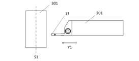
- the workpiece 301 is rotated about its rotation axis S1.
- the material of the workpiece 301 include carbon steel, alloy steel, stainless steel, cast iron, and non-ferrous metals.
- the cutting tool 201 is moved in the direction of the arrow Y1 to bring the cutting tool 201 relatively closer to the rotating workpiece 301.
- the cutting edge 13 of the cutting tool 201 is brought into contact with the rotating workpiece 301 to cut the workpiece 301.
- the workpiece 301 may be cut while allowing coolant to flow out from the first opening 29.
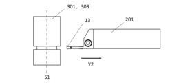
- the cutting tool 201 is moved in the direction of the arrow Y2 to move the cutting tool 201 relatively away from the workpiece 301, thereby obtaining a machined product 303.
- the cutting workpiece 303 is obtained by moving the cutting tool 201, but this is not limiting.
- the workpiece 301 may be brought closer to the cutting tool 201.
- the workpiece 301 may be moved away from the cutting tool 201.
- the workpiece 301 may be kept rotating and the process of bringing the cutting blade 13 into contact with different points on the workpiece 301 may be repeated.
- examples of materials for the workpiece 301 include carbon steel, alloy steel, stainless steel, cast iron, and non-ferrous metals.
- the cutting insert [1] extends from the tip to the rear end along a reference axis and has an upper surface having a rake surface region, a lower surface facing the opposite side to the upper surface, a tip surface located on the tip side and having a clearance surface region, a rear end surface located on the rear end side, and a first flow path extending from the tip surface to the rear end surface, and the first flow path may have a first region extending from the tip surface toward the rear end side and having an inner diameter that increases toward the rear end side, and a second region extending from the rear end surface toward the tip side and having an inner diameter that increases toward the tip side.
- the first region may be inclined relative to the second region.
- the central axis of the first region may be spaced apart from the upper surface toward the rear end, and the central axis of the second region may be spaced apart from the upper surface toward the front end.
- the first region may be connected to the second region.
- the first region may have a first flow path wall located on the side of the upper surface
- the second region may have a second flow path wall located on the side of the upper surface and connected to the first flow path wall
- the first flow path wall may be spaced apart from the upper surface toward the rear end side
- the second flow path wall may be spaced apart from the upper surface toward the front end side
- the first region may further have a third flow path wall located on the lower surface side
- the second region may further have a fourth flow path wall located on the lower surface side and connected to the third flow path wall, and in a cross section passing through the central axis of the first region and the central axis of the second region, the angle between the first flow path wall and the second flow path wall may be larger than the angle between the third flow path wall and the fourth flow path wall.
- the first flow passage may further have a central region located at the center of the first flow passage in the direction along the reference axis, and the first flow passage may have a maximum inner diameter in the central region.
- the cutting tool includes a rod-shaped holder extending from one end to the other end along an axis, and a cutting insert according to any one of [1] to [7] above that is attached to the holder, and the holder may have a restraining surface that contacts the rear end surface, an opening located on the restraining surface and connected to the first flow path, and a second flow path that extends from the opening toward the other end.
- the method for manufacturing a machined product may include a step of rotating a workpiece, a step of bringing the cutting tool described above in [8] into contact with the rotating workpiece, and a step of removing the cutting tool from the workpiece.
Landscapes
- Engineering & Computer Science (AREA)
- Mechanical Engineering (AREA)
- Cutting Tools, Boring Holders, And Turrets (AREA)
Priority Applications (2)
| Application Number | Priority Date | Filing Date | Title |
|---|---|---|---|
| DE112023006047.9T DE112023006047T5 (de) | 2023-03-24 | 2023-11-24 | Schneideinsatz, schneidwerkzeug und verfahren zur herstellung eines maschinell bearbeiteten produkts |
| JP2025509700A JPWO2024202230A1 (https=) | 2023-03-24 | 2023-11-24 |
Applications Claiming Priority (2)
| Application Number | Priority Date | Filing Date | Title |
|---|---|---|---|
| JP2023048470 | 2023-03-24 | ||
| JP2023-048470 | 2023-03-24 |
Publications (1)
| Publication Number | Publication Date |
|---|---|
| WO2024202230A1 true WO2024202230A1 (ja) | 2024-10-03 |
Family
ID=92903821
Family Applications (1)
| Application Number | Title | Priority Date | Filing Date |
|---|---|---|---|
| PCT/JP2023/042173 Ceased WO2024202230A1 (ja) | 2023-03-24 | 2023-11-24 | 切削インサート、切削工具及び切削加工物の製造方法 |
Country Status (3)
| Country | Link |
|---|---|
| JP (1) | JPWO2024202230A1 (https=) |
| DE (1) | DE112023006047T5 (https=) |
| WO (1) | WO2024202230A1 (https=) |
Citations (7)
| Publication number | Priority date | Publication date | Assignee | Title |
|---|---|---|---|---|
| JPH05301104A (ja) * | 1992-04-28 | 1993-11-16 | Sumitomo Electric Ind Ltd | スローアウェイチップおよびその製造方法ならびに切削工具 |
| JP2001198708A (ja) * | 2000-01-11 | 2001-07-24 | Fuji Mach Mfg Co Ltd | 切削工具および切削加工方法 |
| WO2001064376A1 (en) * | 2000-03-03 | 2001-09-07 | Masao Murakawa | Heat absorbing throw-away tip and heat absorbing throw-away tool using the throw-away tip |
| JP2002502711A (ja) * | 1998-02-03 | 2002-01-29 | サンドビック アクティエボラーグ | 冷却溝を備えた切削インサート |
| US20080279644A1 (en) * | 2007-05-09 | 2008-11-13 | Board Of Control Of Michigan Technologycal University | Cutting tool insert having internal microduct for coolant |
| JP2010179412A (ja) * | 2009-02-05 | 2010-08-19 | Jtekt Corp | 切削用工具および切削加工方法 |
| JP2022046273A (ja) * | 2020-09-10 | 2022-03-23 | 三菱マテリアル株式会社 | クーラント孔付き切削インサート |
-
2023
- 2023-11-24 WO PCT/JP2023/042173 patent/WO2024202230A1/ja not_active Ceased
- 2023-11-24 DE DE112023006047.9T patent/DE112023006047T5/de active Pending
- 2023-11-24 JP JP2025509700A patent/JPWO2024202230A1/ja active Pending
Patent Citations (7)
| Publication number | Priority date | Publication date | Assignee | Title |
|---|---|---|---|---|
| JPH05301104A (ja) * | 1992-04-28 | 1993-11-16 | Sumitomo Electric Ind Ltd | スローアウェイチップおよびその製造方法ならびに切削工具 |
| JP2002502711A (ja) * | 1998-02-03 | 2002-01-29 | サンドビック アクティエボラーグ | 冷却溝を備えた切削インサート |
| JP2001198708A (ja) * | 2000-01-11 | 2001-07-24 | Fuji Mach Mfg Co Ltd | 切削工具および切削加工方法 |
| WO2001064376A1 (en) * | 2000-03-03 | 2001-09-07 | Masao Murakawa | Heat absorbing throw-away tip and heat absorbing throw-away tool using the throw-away tip |
| US20080279644A1 (en) * | 2007-05-09 | 2008-11-13 | Board Of Control Of Michigan Technologycal University | Cutting tool insert having internal microduct for coolant |
| JP2010179412A (ja) * | 2009-02-05 | 2010-08-19 | Jtekt Corp | 切削用工具および切削加工方法 |
| JP2022046273A (ja) * | 2020-09-10 | 2022-03-23 | 三菱マテリアル株式会社 | クーラント孔付き切削インサート |
Also Published As
| Publication number | Publication date |
|---|---|
| JPWO2024202230A1 (https=) | 2024-10-03 |
| DE112023006047T5 (de) | 2026-01-15 |
Similar Documents
| Publication | Publication Date | Title |
|---|---|---|
| CN109562458B (zh) | 切削工具用刀架及切削工具、以及使用它们的切削加工物的制造方法 | |
| JP7304989B2 (ja) | 切削インサート、切削工具及び切削加工物の製造方法 | |
| CN111148590B (zh) | 切削刀片、切削刀具以及切削加工物的制造方法 | |
| JP7480291B2 (ja) | 切削インサート、切削工具及び切削加工物の製造方法 | |
| CN107073594A (zh) | 刀架、切削工具以及切削加工物的制造方法 | |
| CN115666827B (zh) | 切削刀片、切削刀具及切削加工物的制造方法 | |
| CN105682835A (zh) | 切削镶刀及切削工具、使用它们的切削加工物的制造方法 | |
| JP7155407B2 (ja) | 切削インサート、切削工具及び切削加工物の製造方法 | |
| JP7630641B2 (ja) | 切削インサート、切削工具、及び切削加工物の製造方法 | |
| CN110944777B (zh) | 切削刀片、切削工具以及切削加工物的制造方法 | |
| CN113474110B (zh) | 车削刀具及切削加工物的制造方法 | |
| CN116568432B (zh) | 切削刀片、切削刀具以及切削加工物的制造方法 | |
| CN114951719A (zh) | 切削刀片 | |
| WO2024202230A1 (ja) | 切削インサート、切削工具及び切削加工物の製造方法 | |
| JP7594672B2 (ja) | 切削インサート、切削工具及び切削加工物の製造方法 | |
| WO2024048257A1 (ja) | 切削インサート、切削工具、及び切削加工物の製造方法 | |
| CN120344336A (zh) | 切削刀具以及切削加工物的制造方法 | |
| CN107708904A (zh) | 切削工具以及切削加工物的制造方法 | |
| CN115551663B (zh) | 切削刀片、切削刀具以及切削加工物的制造方法 | |
| JP7779820B2 (ja) | 切削インサート、切削工具及び切削加工物の製造方法 | |
| US20260084219A1 (en) | Cutting insert, cutting tool, and method for manufacturing machined product | |
| JP7527489B2 (ja) | ホルダ、切削工具及び切削加工物の製造方法 | |
| WO2025182455A1 (ja) | 切削インサート、切削工具及び切削加工物の製造方法 | |
| WO2026034060A1 (ja) | 切削インサート、切削工具及び切削加工物の製造方法 | |
| JP7239480B2 (ja) | 切削インサート、切削工具及び切削加工物の製造方法 |
Legal Events
| Date | Code | Title | Description |
|---|---|---|---|
| 121 | Ep: the epo has been informed by wipo that ep was designated in this application |
Ref document number: 23930856 Country of ref document: EP Kind code of ref document: A1 |
|
| ENP | Entry into the national phase |
Ref document number: 2025509700 Country of ref document: JP Kind code of ref document: A |
|
| WWE | Wipo information: entry into national phase |
Ref document number: 2025509700 Country of ref document: JP |
|
| WWE | Wipo information: entry into national phase |
Ref document number: 112023006047 Country of ref document: DE |
|
| WWP | Wipo information: published in national office |
Ref document number: 112023006047 Country of ref document: DE |
|
| 122 | Ep: pct application non-entry in european phase |
Ref document number: 23930856 Country of ref document: EP Kind code of ref document: A1 |