WO2024202016A1 - 内燃機関の吸気構造 - Google Patents
内燃機関の吸気構造 Download PDFInfo
- Publication number
- WO2024202016A1 WO2024202016A1 PCT/JP2023/013593 JP2023013593W WO2024202016A1 WO 2024202016 A1 WO2024202016 A1 WO 2024202016A1 JP 2023013593 W JP2023013593 W JP 2023013593W WO 2024202016 A1 WO2024202016 A1 WO 2024202016A1
- Authority
- WO
- WIPO (PCT)
- Prior art keywords
- passage
- intake
- opening
- combustion chamber
- sub
- Prior art date
- Legal status (The legal status is an assumption and is not a legal conclusion. Google has not performed a legal analysis and makes no representation as to the accuracy of the status listed.)
- Ceased
Links
Images





Classifications
-
- F—MECHANICAL ENGINEERING; LIGHTING; HEATING; WEAPONS; BLASTING
- F02—COMBUSTION ENGINES; HOT-GAS OR COMBUSTION-PRODUCT ENGINE PLANTS
- F02B—INTERNAL-COMBUSTION PISTON ENGINES; COMBUSTION ENGINES IN GENERAL
- F02B31/00—Modifying induction systems for imparting a rotation to the charge in the cylinder
- F02B31/04—Modifying induction systems for imparting a rotation to the charge in the cylinder by means within the induction channel, e.g. deflectors
-
- F—MECHANICAL ENGINEERING; LIGHTING; HEATING; WEAPONS; BLASTING
- F02—COMBUSTION ENGINES; HOT-GAS OR COMBUSTION-PRODUCT ENGINE PLANTS
- F02B—INTERNAL-COMBUSTION PISTON ENGINES; COMBUSTION ENGINES IN GENERAL
- F02B31/00—Modifying induction systems for imparting a rotation to the charge in the cylinder
- F02B31/04—Modifying induction systems for imparting a rotation to the charge in the cylinder by means within the induction channel, e.g. deflectors
- F02B31/06—Movable means, e.g. butterfly valves
-
- F—MECHANICAL ENGINEERING; LIGHTING; HEATING; WEAPONS; BLASTING
- F02—COMBUSTION ENGINES; HOT-GAS OR COMBUSTION-PRODUCT ENGINE PLANTS
- F02B—INTERNAL-COMBUSTION PISTON ENGINES; COMBUSTION ENGINES IN GENERAL
- F02B31/00—Modifying induction systems for imparting a rotation to the charge in the cylinder
- F02B31/08—Modifying induction systems for imparting a rotation to the charge in the cylinder having multiple air inlets
-
- Y—GENERAL TAGGING OF NEW TECHNOLOGICAL DEVELOPMENTS; GENERAL TAGGING OF CROSS-SECTIONAL TECHNOLOGIES SPANNING OVER SEVERAL SECTIONS OF THE IPC; TECHNICAL SUBJECTS COVERED BY FORMER USPC CROSS-REFERENCE ART COLLECTIONS [XRACs] AND DIGESTS
- Y02—TECHNOLOGIES OR APPLICATIONS FOR MITIGATION OR ADAPTATION AGAINST CLIMATE CHANGE
- Y02T—CLIMATE CHANGE MITIGATION TECHNOLOGIES RELATED TO TRANSPORTATION
- Y02T10/00—Road transport of goods or passengers
- Y02T10/10—Internal combustion engine [ICE] based vehicles
- Y02T10/12—Improving ICE efficiencies
Definitions
- the disclosed technology relates to the intake structure of an internal combustion engine.
- Patent Document 1 discloses a structure that orients the tumble flow passage opening toward the combustion chamber to strengthen the tumble flow, with the aim of improving fuel efficiency.
- the disclosed technology aims to strengthen the formation of vortex airflow inside the cylinder and improve combustion efficiency. This will ultimately contribute to improved fuel economy and energy efficiency.
- An intake structure for an internal combustion engine is an intake structure for an internal combustion engine, in which a main passage (6B) and a sub-passage (6A) are formed by a partition portion (65) that divides an intake passage (6) into upper and lower portions along a passage direction, and intake air is guided to the sub-passage (6A) or to the main passage (6B) and the sub-passage (6A) depending on an operating state of the internal combustion engine (4),
- An opening (Wa) of an inlet section (410) formed in a substantially straight line on the downstream side of the sub-passage (6A) communicates with a combustion chamber (32) via the main passage (6B),
- the opening (Wa) is formed such that a center line (501) of the opening (Wa) is offset from a center line (502) of an outer width (WA) of the sub-passage (6A) by an offset amount (503) set in a direction intersecting with the passage direction,
- the disclosed technology can provide an intake structure for an internal combustion engine that can strengthen the formation of vortex airflow inside the cylinder and improve combustion efficiency.
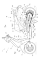
- FIG. 1 is a side view of a vehicle according to an embodiment.
- 1 is a diagram illustrating a structure of an internal combustion engine according to an embodiment
- 1 is a diagram illustrating an intake structure of an internal combustion engine according to an embodiment
- 4 is a diagram showing a downstream structure where a main passage and an auxiliary passage are connected to a combustion chamber in an intake structure of an internal combustion engine according to an embodiment.
- FIG. FIG. 2 is a diagram showing a schematic structure of a sub-passage in a top view of a combustion chamber in the intake structure of the internal combustion engine according to the embodiment
- 4A is a bottom view of the combustion chamber as seen from the direction of the arrow 4A in FIG.
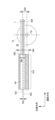
- FIG. 4 is a diagram illustrating a cross-sectional shape of a sub-passage 6A.
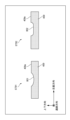
- FIG. 4 is a diagram illustrating a cross-sectional shape of an intake guide portion 409 in the intake structure of the internal combustion engine according to the embodiment.
- 11A and 11B are schematic diagrams illustrating a comparison between an intake flow in a comparative example and an intake flow in the intake structure of the embodiment.
- directions such as front, back, left, right, up and down in the description and claims of this specification shall refer to the vehicle directions in a saddle-type vehicle when the internal combustion engine according to this embodiment is mounted on the saddle-type vehicle.
- the saddle-type vehicle is a scooter-type motorcycle (hereinafter simply referred to as a "motorcycle").
- arrows FR in the figure indicate the front of the vehicle
- LH indicate the left side of the vehicle
- RH indicate the right side of the vehicle
- UP indicate the top of the vehicle.
- FIG. 1 shows an outline of a left side view of a motorcycle 1 equipped with an intake structure for an internal combustion engine according to this embodiment.
- the front body 1A and the rear body 1B are connected via a low floor section 1C (footrest section), and the body frame 2 that forms the skeleton of the body is generally composed of a down frame 21 and a main frame 22.
- a down frame 21 extends downward from a head pipe 20 at the front portion 1A of the vehicle body, and is connected to lower frame portions 22a of a pair of left and right main frames 22 that extend approximately horizontally rearward from the lower end of the down frame 21.
- the main frames 22 extend diagonally rearward and upward from the rear ends of the lower frame portions 22a, forming a pair of left and right inclined portions 22b, and the upper portions of the inclined portions 22b are further bent to form a pair of left and right horizontal portions 22c that extend approximately horizontally rearward.
- a storage box (also called a helmet box) 11 is supported on the inclined portion 22b and horizontal portion 22c of the main frame 22, and a passenger seat 12 is positioned above and covers it.
- a handlebar 13 is provided above and journalled on the head pipe 20, and a front fork 14 extends below and journals a front wheel 15 at its lower end.
- a power unit support bracket 23 protrudes rearward from the inclined portion 22b of the main frame 22, and a swing-type power unit (hereinafter simply referred to as the "power unit") 3 is connected to the power unit support bracket 23 via a link member 24 so that it can swing up and down.
- a swing-type power unit hereinafter simply referred to as the "power unit”
- the motorcycle 1 of this embodiment has an upper link type support structure for the power unit 3, which results in space being available below the front of the power unit 3 for the catalytic converter 49.
- the floor section 1C is provided on the pair of left and right lower frame sections 22a of the main frame 22 of the vehicle body frame 2, and the upper part of the lower frame section 22a is covered by a floor cover 10c, and the left and right sides are covered in the front-rear direction by floor side covers 10d, and the lower part is covered by an undercover 10e.
- a rear cushion 18 is interposed between the rear of the power transmission unit 5 and the horizontal portion 22c at the rear of the main frame 22.
- An intake port 45 is provided on the intake side flange surface 43b, to which the inlet manifold 61 is fastened via the insulator 60.
- the upstream side of the throttle body 62 is connected via a connecting tube 63 to an air cleaner 64 attached to the top of the power transmission unit 5.
- an approximately cylindrical catalytic converter 49 oriented in the vehicle width direction is installed in the upstream exhaust pipe 48a connected to the exhaust port outlet 47a at the bottom of the cylinder head 43, and a catalyst for purifying exhaust gas, such as a three-way catalyst, is loaded inside it.
- the downstream exhaust pipe 48b connected to the outlet of the catalytic converter 49 bends backward and extends rearward along the right side of the vehicle, connecting to a muffler (not shown) on the right side of the rear wheel 17.
- FIG. 2 is a right sectional side view taken along the cylinder axis C of the cylinder block 42, the cylinder head 43, the head cover 44 and their surroundings of the power unit 3 in FIG.
- the crankcase 30 is formed by combining a left case half 30L and a right case half (not shown) that are split into left and right halves.
- the left case half 30L extends rearward to form the power transmission section 5 that houses the transmission device, including the long belt-type continuously variable transmission 51 and reduction gear mechanism 52, between the crankshaft 41 and the rear axle 52a of the rear wheel 17.
- the piston 33 that reciprocates within the cylinder bore 42a of the cylinder block 42 is connected to the crank pin 41a of the crankshaft 41 of the crankcase 30 by a connecting rod 34.
- the combustion chamber 32 is formed between the top surface 33a of the piston 33, which is slidably fitted into the cylinder bore 42a of the cylinder block 42, and the ceiling surface 43a of the cylinder head 43, which faces the top surface 33a.
- an inlet manifold 61 connected to the intake port 45 of the cylinder head 43 has a throttle body 62 fastened to it on the upstream side via a reed valve 8 (described below).
- a reed valve 8 (described below).
- a configuration using the reed valve 8 is used as an example, but this embodiment can also be applied to a configuration that does not use the reed valve 8.
- the throttle body 62 has a throttle valve 62a mounted inside the intake passage 6, which rotates around a throttle valve shaft 62b to open and close the intake passage 6 and adjust the intake flow rate.
- 31 is a bracket part that protrudes upward from the top of the crankcase 30 and is used to suspend the power unit 3 on the vehicle frame 2.
- bracket portion 31 is journaled via a link member 24 to a power unit support bracket 23 that protrudes rearward from the inclined portion 22b of the main frame 22, and the power unit 3 swings up and down relative to the vehicle frame 2.
- the rear end of the power unit 3, which swings up and down, is supported on the horizontal part 22c of the main frame 22 by the rear cushion 18.
- an inlet manifold 61 is connected to the front of the throttle body 62, i.e., downstream of the intake, and bends downward, connecting to the intake port 45 at the top of the cylinder head 43 with an insulator 60 in between.
- a fuel injection valve 39 is attached to the downstream end of the inlet manifold 61, and fuel is injected toward the intake valve port 35. Fuel is injected in the direction of the injection center line I shown in Figure 2. Since the fuel injection from the fuel injection valve 39 has a certain spread, a recess 67a is provided on the outer periphery of the main passage head inlet opening 67 to avoid the injected fuel.
- the fuel hose (not shown) connected to the fuel injection valve 39 is routed rearward and connected to the fuel tank 16 located above the rear wheel 17 via a fuel pump device (not shown).
- the internal combustion engine 4 employs a single-cylinder SOHC type two-valve system, and a valve mechanism 9 is provided in the cylinder head 43.
- a head cover 44 is placed over the cylinder head 43 to cover the valve mechanism 9.
- an endless cam chain (not shown) is stretched between the camshaft 90 and the crankshaft 41, passing through a cam chain chamber (not shown) provided on one side of the crankcase 30, cylinder block 42, and cylinder head 43 in the direction of the crankshaft 41, and the camshaft 90 rotates in synchronization with the crankshaft 41 at half the rotational speed.
- an ignition plug is inserted into the cylinder head 43 from the side opposite the cam chain chamber (the other side in the direction of the crankshaft 41) toward the combustion chamber 32.
- an intake valve port 35 and an exhaust valve port 36 open to the ceiling surface 43a of the combustion chamber 32, and from these, an intake port 37 and an exhaust port 38 are formed, each of which extends while curving away from each other vertically.
- the upstream end of the intake port 37 opens toward the top of the cylinder head 43 to form the intake port 45, which is connected to the inlet manifold 61 to form a continuous intake passage 6, and the throttle body 62 is connected to the upstream side of the inlet manifold 61.
- the downstream end of the exhaust port 38 forms an exhaust port outlet 47, which opens downward toward the cylinder head 43 and is connected to the upstream exhaust pipe 48a ( Figure 1).
- a cylindrical intake valve guide 71 is fitted integrally to the curved outer wall portion 37a of the intake port 37 in the cylinder head 43, and an intake valve 73 slidably supported by the intake valve guide 71 opens and closes the intake valve opening 35 of the intake port 37 facing the combustion chamber 32.
- the exhaust valve guide 72 is integrally fitted to the curved outer wall portion 38a of the exhaust port 38 in the cylinder head 43, and an exhaust valve 74 slidably supported by the exhaust valve guide 72 opens and closes the exhaust valve opening 36 of the exhaust port 38 facing the combustion chamber 32.
- the pair of intake valves 73 and exhaust valves 74 are positioned based on a positional relationship in which the shafts 73c and 74c are inclined in a V-shape.
- the intake valve 73 and exhaust valve 74 are biased upward by a valve spring 75 so that their umbrella portions 73a, 74a close the intake valve port 35 and exhaust valve port 36 that face the combustion chamber 32.
- the stem ends 73b, 74b of the intake valve 73 and exhaust valve 74 are pushed down by the intake rocker arm 91 and exhaust rocker arm 92 that swing against the intake cam and exhaust cam of the camshaft 90, opening the intake valve 73 and exhaust valve 74 at a predetermined timing, connecting the intake port 37 and the combustion chamber 32, and connecting the exhaust port 38 and the combustion chamber 32, and allowing intake and exhaust to occur at a predetermined timing.
- An inlet manifold 61 is connected to the upstream end of the intake port 37 of the internal combustion engine 4 via an insulator 60 to form a continuous intake passage 6, and a throttle body 62 is connected to the upstream side of the inlet manifold 61 via a reed valve 8.
- the throttle body 62 has an intake passage 62c with a generally circular cross section that constitutes part of the intake passage 6 that is connected to the combustion chamber 32 of the internal combustion engine 4, and its upstream side is connected to an air cleaner 64 (see Figure 1) via a connecting tube 63.
- the throttle body 62 is equipped with a throttle valve 62a.
- the throttle valve 62a is a single butterfly-type throttle valve that is rotatably supported within the throttle body 62 by a throttle valve shaft 62b that is oriented substantially horizontally and perpendicular to the intake flow direction F of the intake passage 62c, i.e., perpendicular to the central axis X of the intake passage 62c, and can variably control the flow area of the intake passage 62c to open and close the intake passage 62c.
- the throttle valve 62a can be rotated in the opening direction (clockwise as shown in FIG. 2) by the driver's operation, and is biased in the closing direction (clockwise) by a return spring (not shown).
- the intake passage 62c of the throttle body 62 is oriented approximately horizontally.
- the intake passage 6 is divided into upper and lower sections along the intake flow direction by a partition 65 (partition wall) from the inlet manifold 61 to the intake port 37.
- the intake passage 6 is configured so that the intake air that passes through the intake passage 6 generates a tumble flow T in the combustion chamber 32.
- the intake passage 6 is divided by the partition 65 into a tumble passage 6A on the lower side of the intake passage 6 and a main passage 6B on the upper side of the intake passage 6.
- the tumble passage is an intake passage for generating a tumble flow T in the combustion chamber 32 when the throttle valve 62a is at a low opening, that is, when the internal combustion engine 4 is at a low load.
- the tumble passage 6A is also referred to as an auxiliary passage.
- the tumble passage 6A is disposed below the intake passage 6, and the main passage 6B is disposed above the intake passage 6, but in this embodiment, the vertical arrangement of the tumble passage 6A (auxiliary passage) and the main passage 6B is not limited to the arrangement shown in FIG. 2.
- the partition section 65 is made up of a partition section 65A on the inlet manifold side, a partition section 65B on the insulator side, and a partition section 65C on the intake port side, which are arranged continuously from the upstream side to the downstream side of the intake flow.
- the main passage 6B on the upper side of the figure and the tumble passage 6A on the lower side of the figure are each formed by dividing the intake passage 6 into upper and lower sections by a partition section 65.
- ST31 in FIG. 3 is a perspective view of the downstream side of the reed valve 8.
- ST32 in FIG. 3 is a perspective view of the downstream side of the reed valve 8 with the reed valve body 81 and the reed valve element 87 fastened thereto.
- the reed valve 8 has a reed valve body 81 that forms the entire valve, and the mounting flange portion 85 is sandwiched and fastened between the downstream end of the throttle body 62 and the upstream end of the inlet manifold 61.
- the surface where the reed valve body 81 is attached to the throttle body 62 is provided with an inlet opening 82 that coincides with the downstream opening 62d of the throttle body 62, and a valve intake passage 80 that communicates with the intake passage 62c of the throttle body 62 is formed within the reed valve body 81.
- the downstream end 83 of the reed valve body 81 abuts against the upstream end 65Aa of the partition portion 65A and has an opening 84 that matches the upstream end opening 6Aa of the tumble passage 6A.
- the upper part of the reed valve body 81 is formed to slope from the rear of the mounting flange portion 85 to the lower downstream part of the reed valve 8, and the sloped surface 81a has an opening 86 that connects the valve intake passage 80 inside the reed valve body 81 to the main passage 6B.
- One end 87a of the reed valve body 87 is fastened to the mounting flange portion 85 by a screw 87c so as to cover the opening 86.
- the other end 87b of the reed valve body 87 is a free swinging end, and the other end 87b of the reed valve body 87 abuts against the downstream end portion 83 formed on the downstream side of the reed valve body 81.
- the throttle valve 62a When the throttle valve 62a is at a low opening, that is, when the negative pressure on the downstream side of the reed valve body 87 is smaller than a certain value, the other end 87b of the reed valve body 87 keeps the opening 86 closed, and intake air flows from the valve intake passage 80 in the reed valve body 81 exclusively to the tumble passage 6A of the inlet manifold 61.
- the throttle valve 62a When the throttle valve 62a is highly open, that is, when the internal combustion engine 4 is under high load and the negative pressure downstream of the reed valve body 87 exceeds a certain value, the other end 87b of the reed valve body 87 bends to open the opening 86, and intake air flows from the valve intake passage 80 in the reed valve body 81 to the main passage 6B of the inlet manifold 61.
- Fig. 4 is a diagram showing the intake structure on the downstream side where the main passage 6B and the sub passage 6A are connected (communicated) to the combustion chamber 32.
- Fig. 4 shows a side view of the combustion chamber 32 with the intake valve 73 open.
- Fig. 5 is a diagram showing a schematic view of the structure of the sub passage 6A in a top view of the combustion chamber 32 of the internal combustion engine 4.
- a partition 65 separates the intake passage 6 into upper and lower sections along the passage direction, forming a main passage 6B and a sub-passage 6A, and depending on the operating state of the internal combustion engine 4, intake air is guided to the sub-passage 6A or to both the main passage 6B and the sub-passage 6A.
- the opening Wa of the approach section 410 which is formed in a substantially straight line downstream of the sub-passage 6A, communicates with the combustion chamber 32 via the main passage 6B.
- the approach section 410 is formed based on a positional relationship in which the axis 419 of the secondary passage 6A in the approach section 410 is inclined at a relative angle ⁇ 1 set with respect to the shaft portion 73c of the intake valve 73 in the open state.
- the relative angle ⁇ 2 indicates, for example, the relative angle of the approach section 410 with respect to the fastening surface that attaches the cylinder head 43 to the cylinder block 42.
- the intake structure of the internal combustion engine 4 has a junction 420 where intake air 407 flowing from the main passage 6B to the combustion chamber 32 and intake air 408 flowing from the secondary passage 6A to the combustion chamber 32 join together.
- a substantially linear flat surface 416 is provided on the surface of the main passage 6B on the secondary passage 6A side of the junction 420.
- An opening is formed in the flat surface 416 to guide the intake air flow f from the secondary passage 6A side to the junction 420.
- the flat surface 416 is formed substantially parallel to the shaft 73c of the intake valve 73.
- the sub-passage 6A is also provided with a substantially linear intake guide section 409 that guides the intake flow f from the opening end 506 of the opening Wa toward the junction section 420 or the combustion chamber 32.
- the opening Wa of the inlet section 410 of the sub-passage 6A which is formed on the downstream side in the passage direction, is connected to the combustion chamber 32 via the main passage 6B.
- the opening Wa is formed based on a positional relationship in which the center line 501 of the opening Wa is eccentric with respect to the center line 502 of the outer width WA of the sub-passage 6A by a first eccentricity amount (offset amount 503) set in a direction intersecting (approximately perpendicular) the passage direction.
- the opening Wa is also formed based on a positional relationship in which the center line 501 of the opening Wa is eccentric with respect to the center line 504 (center line along the passage direction) of the shaft portion 73c of the intake valve 73 by a second eccentricity amount (offset amount 505).
- the center line 501 of the opening Wa is eccentric to the center line 502 of the outer width WA of the sub-passage 6A by a first eccentricity amount (offset amount 503).
- the center line 501 of the opening Wa is eccentric to the center line 504 (center line along the passage direction) of the shaft portion 73c of the intake valve 73 by a second eccentricity amount (offset amount 505).
- the hatched portion extending from the opening end 506 of the opening Wa of the bypass passage 6A to the right side of the paper indicates the projection surface of the opening Wa (the projection surface of the cross-sectional shape in a direction perpendicular to the direction in which the approach section 410 of the bypass passage 6A extends).
- the projection surface of the opening Wa is formed as a virtual, approximately cylindrical region (hereinafter also referred to as the cross-sectional shape region of the opening Wa) obtained by extending the cross-sectional shape of the opening Wa of the secondary passage 6A in a direction extending from the opening end 506 toward the inside of the combustion chamber 32.
- the projection surface of the opening Wa (cross-sectional shape region of the opening Wa) is projected in a substantially linear manner from the opening end 506 toward the combustion chamber 32, and has a spatial spread in a direction perpendicular to the paper surface.
- the intake flow f flowing through the secondary passage 6A is output (supplied) from the opening end 506 of the opening Wa of the secondary passage 6A into the combustion chamber 32 so as to flow within the virtual, approximately cylindrical region (cross-sectional shape region of the opening Wa).
- the opening Wa has a cross-sectional shape that is generally oval or rectangular and extends horizontally in the direction of the offset amount 503.
- the intake flow f passes through the approach section 410, which is formed in a straight line downstream of the secondary passage 6A, and is output from the opening Wa.
- the intake flow f output from the opening Wa becomes a flow directed in a substantially straight line as it flows through the approach section 410.
- the intake guide section 409 supplies the intake flow f output from the opening Wa into the combustion chamber 32 while maintaining the substantially straight direction.
- the imaginary, approximately cylindrical region (cross-sectional shape region of the opening Wa) having a spatial extent according to the cross-sectional shape of the opening Wa is formed in the combustion chamber 32 so as not to come into contact with the umbrella portion 73a of the intake valve 73 or the ceiling surface 43a of the combustion chamber 32 when the intake valve 73 is open, as shown in FIG. 4.
- the imaginary, approximately cylindrical region (cross-sectional shape region of the opening Wa) formed as the projection surface of the opening Wa is formed in the combustion chamber 32 so as not to come into contact with the shaft portion 73c of the intake valve 73 when open, as shown in FIG. 5, when viewed from above the combustion chamber 32 of the internal combustion engine 4.
- the imaginary, approximately cylindrical region (cross-sectional shape region of the opening Wa) formed as the projection surface of the opening Wa is formed so as not to come into contact with the shaft portion 73c of the intake valve 73 when open, and so as not to come into contact with the umbrella portion 73a of the intake valve 73 when the intake valve 73 is open.
- the opening Wa of the sub-passage 6A and the approach section 410 are formed so that a virtual, roughly cylindrical area (the cross-sectional area of the opening Wa) is formed within the combustion chamber 32.
- FIG. 6A is a bottom view of the combustion chamber 32 as seen from the direction of the arrow 4A in FIG. 4.
- the hatched portion illustrates the projection surface of the opening Wa of the secondary passage 6A.
- the intake flow f flowing through the secondary passage 6A is output (supplied) from the opening Wa of the secondary passage 6A into the combustion chamber 32 so as to flow within the projection surface of the opening Wa in the combustion chamber 32.
- the imaginary approximately cylindrical area (cross-sectional shape area of the opening Wa) formed as the projection surface of the opening Wa is formed in the combustion chamber 32 so as not to come into contact with the valve seat edge 77 of the intake valve 73 in the open state in the side view and bottom view of the combustion chamber 32 with the intake valve 73 open, as shown in FIG. 4 and FIG.
- the imaginary approximately cylindrical area (cross-sectional shape area of the opening Wa) is formed so as not to come into contact with the shaft portion 73c and the umbrella portion 73a of the intake valve 73 in the open state, as well as the valve seat edge 77 of the intake valve 73.
- the opening Wa of the sub-passage 6A and the approach section 410 are formed so that a virtual, roughly cylindrical area (the cross-sectional area of the opening Wa) is formed within the combustion chamber 32.
- the opening Wa may be formed in two branches.
- one projection surface and the other projection surface of the opening Wa of the auxiliary passage 6A formed in two branches may be formed in the combustion chamber 32 so as not to come into contact with the valve seat edge 77 of the open intake valve 73 in a side view and a bottom view of the combustion chamber 32 with the intake valve 73 open, as shown in FIGS. 4 and 6A, respectively.
- one projection surface (one cross-sectional shape area of the opening Wa) and the other projection surface (the other cross-sectional shape area of the opening Wa) of the opening Wa of the auxiliary passage 6A formed in two branches are formed in the left-right direction of the paper, sandwiching the shaft portion 73c.
- the imaginary, approximately cylindrical region (one cross-sectional area of the opening Wa) formed as one projection surface of the opening Wa, and the imaginary, approximately cylindrical region (the other cross-sectional area of the opening Wa) formed as the other projection surface of the opening Wa are formed so as not to come into contact with the shaft portion 73c and umbrella portion 73a of the intake valve 73 in the open state, or with the valve seat edge 77 of the intake valve 73 (FIG. 6B).
- Fig. 7 is a diagram showing a cross-sectional shape of the auxiliary passage 6A.
- the direction perpendicular to the paper surface indicates the passage direction of the intake passage 6
- the left-right direction of the paper surface indicates the width direction of the internal combustion engine 4 that intersects (substantially perpendicular) with the passage direction
- the up-down direction of the paper surface indicates the up-down direction of the internal combustion engine 4 that intersects (substantially perpendicular) with the passage direction and the intersecting direction.
- the sub-passage 6A has a cross-sectional shape in the form of a generally elliptical opening Wa or a generally rectangular opening Wa that is elongated horizontally in the direction of the offset amount 503.
- ST71 shows an example in which the opening Wa of the sub-passage 6A is generally elliptical
- ST72 shows an example in which the opening Wa of the sub-passage 6A is generally rectangular.
- the opening Wa is formed in a positional relationship in which the center line 501 of the opening Wa of the sub-passage 6A is eccentric to the center line 502 of the external width WA of the sub-passage 6A by a first eccentricity amount (offset amount 503).
- the intake guide section 409 extends in a substantially straight line from the opening end 506 of the opening Wa toward the combustion chamber 32, and is formed so that it can be connected to the inner surface of the opening Wa without any steps.
- a recess having a curvature that matches the cross-sectional shape of the opening Wa is formed on the upper surface 409a of the intake guide section 409.
- Figure 8 is a diagram showing a schematic cross-sectional shape of the intake induction section 409.
- the coordinate system in Figure 8 is the same as that in Figure 7, with the direction perpendicular to the paper surface indicating the passage direction of the intake passage 6, and the left-right direction of the paper surface indicating the width direction of the internal combustion engine 4 which intersects (approximately perpendicular) with the passage direction. Additionally, the up-down direction of the paper surface indicates the up-down direction of the internal combustion engine 4 which intersects (approximately perpendicular) with the passage direction and the intersecting direction.
- the upper surface 409a of the intake guide section 409 is formed with recesses (801, 802) having a curvature that matches the shape of the opening Wa.
- ST81 shows the cross-sectional shape of the intake guide section 409 corresponding to the example (ST71) in which the opening Wa is formed in a substantially elliptical shape.
- ST82 shows the cross-sectional shape of the intake guide section 409 corresponding to the example (ST72) in which the opening Wa is formed in a substantially rectangular shape.
- the upper surface 409a of the intake guide section 409 is formed with a recess 801 having a curvature that matches the cross-sectional shape of the lower part of the opening Wa (for example, the shape of the lower half of the approximately oval shape in the vertical direction) in order to connect without any steps with the inner surface of the approximately oval opening Wa.
- the upper surface 409a of the intake guide section 409 is formed with a recess 802 having a curvature that matches the cross-sectional shape of the lower part of the opening Wa (for example, the shape of the lower half of the approximately rectangular shape in the vertical direction) in order to connect without any steps with the inner surface of the approximately rectangular opening Wa.
- recesses 801, 802 on the upper surface 409a of the intake guide section 409, which have a curvature that matches the cross-sectional shape of the lower part of the opening Wa, it becomes possible to connect the recesses 801, 802 (inner surface of the recess) of the intake guide section 409 and the lower part of the opening Wa (inner surface of the lower part) without any steps at the connection part in the passage direction.
- This makes it possible to supply the intake flow f to the combustion chamber 32 without disturbing the flow that is directed in an approximately straight line along the passage direction.
- the intake air flow f which has a spatial expansion according to the cross-sectional shape of the opening Wa, flows through the recesses 801 and 802 (the inner peripheral surfaces of the recesses), so that the flow is directed in a substantially straight line along the passage direction, and the expansion of the intake air flow in the intersecting direction can be suppressed.
- This allows the intake air flow f to be supplied into the combustion chamber 32 without coming into contact with the shaft portion 73c ( Figure 5) of the open intake valve 73.
- the main passage 6B, the sub-passage 6A, and the intake guide section 409 may be molded together with the cylinder head 43, for example, by casting, or may be formed by machining after the cylinder head 43 is molded.
- FIG. 9 is a schematic diagram showing a comparison between the intake flow in a comparative example and the intake flow in the intake structure of the embodiment, where ST91 is a diagram showing the flow of the intake flow f in the comparative example, and ST92 is a diagram showing the flow of the intake flow f in the intake structure of the internal combustion engine 4 in this embodiment.
- a curved portion 900 having a circular arc shape with a predetermined curvature is provided at the confluence 420 in place of the flat surface 416 of the main passage 6B.
- the curved portion 900 has a circular arc shape with a predetermined curvature that curves downward from the open end of the secondary passage 6A toward the combustion chamber 32.
- the intake flow f output (supplied) from the secondary passage 6A leaves the curved portion 900 and is divided into an intake flow f1 that flows toward the combustion chamber 32 and an intake flow f2 that flows upward of the intake valve 73. Of the supplied intake flow f, only the intake flow f1 that flows toward the combustion chamber 32 is used for combustion, which may reduce combustion efficiency.
- ST92 is a diagram showing the flow of the intake flow f by the intake structure of the internal combustion engine 4 in this embodiment.
- the intake flow f output (supplied) from the secondary passage 6A flows over the upper surface of the intake guide portion 409 and is supplied to the combustion chamber 32 while maintaining a flow directed substantially linearly along the passage direction.
- the flat surface 416 is formed in the main passage 6B, so that the open end 506 of the secondary passage 6A can be positioned closer to the combustion chamber 32.
- the intake flow f can be supplied to the combustion chamber 32 while maintaining a flow of the intake flow f directed substantially linearly, compared to the comparative example (ST91). That is, according to the intake structure (ST92) of the internal combustion engine 4 according to the embodiment, the intake flow f for obtaining a more preferable combustion in the combustion chamber 32 can be supplied to the combustion chamber 32.
- a vertical rotating vortex (a rotating vortex on a plane along the cylinder axis C), i.e., a tumble flow T, of the fuel-air mixture can be provided in the combustion chamber 32 in order to obtain more favorable combustion in the combustion chamber 32.
- the disclosed technology can provide an intake structure for an internal combustion engine that can strengthen the formation of an airflow vortex inside the cylinder and improve combustion efficiency.
- the intake structure for an internal combustion engine is an intake structure for an internal combustion engine, in which a main passage (6B) and a sub-passage (6A) are formed by a partition portion (65) that divides an intake passage (6) into upper and lower portions along a passage direction, and intake air is guided to the sub-passage (6A) or to both the main passage (6B) and the sub-passage (6A) depending on an operating state of the internal combustion engine (4),
- An opening (Wa) of an inlet section (410) formed in a substantially straight line on the downstream side of the sub-passage (6A) communicates with a combustion chamber (32) via the main passage (6B),
- the opening (Wa) is formed based on a positional relationship in which a center line (501) of the opening (Wa) is eccentric with respect to a center line (502) of an outer width (WA) of the sub-passage (6A) by an offset amount (503) set in a direction
- the intake structure of the internal combustion engine described in item 1 can reduce the obstruction of the intake air flow from the opening end 506 of the secondary passage 6A toward the inside of the cylinder, strengthening the formation of vortex airflow inside the cylinder and improving combustion efficiency.
- the area is formed so as not to come into contact with the shaft portion (73c) of the intake valve (73) when viewed from the top, and so as not to come into contact with the umbrella portion (73a) of the intake valve (73) when viewed from the side.
- the intake structure of the internal combustion engine in item 2 prevents the intake air flow from the opening end 506 of the secondary passage 6A toward the inside of the cylinder from being obstructed by contact with the valve seat edge 77, improving combustion efficiency. This strengthens the formation of vortex airflow inside the cylinder, improving combustion efficiency.
- the intake air (407) flowing from the main passage (6B) to the combustion chamber (32) and the intake air (408) flowing from the sub-passage (6A) to the combustion chamber (32) further include a junction (420) where they join together,
- a substantially linear flat surface (416) is provided on a surface of the main passage (6B) on the side of the sub-passage (6A) at the junction (420).
- the position of the opening end 506 of the secondary passage 6B can be brought closer to the junction 420 compared to the structure (ST91) in which the curvature section 900 having an arc shape with a predetermined curvature is provided.
- This makes it easier to adjust the insertion angle (relative angle ⁇ 1: Figure 1) of the secondary passage 6A toward the junction 420 and the combustion chamber 32, and further increases the directionality of the intake flow f. This strengthens the formation of vortex airflow inside the cylinder, making it possible to improve combustion efficiency.
- the position of the opening end 506 of the secondary passage 6B can be brought closer to the junction 420, and the intake flow f can be supplied to the junction 420 through the opening formed in the flat surface 416. This strengthens the formation of an airflow vortex inside the cylinder, making it possible to improve combustion efficiency.
- the flat surface (416) is formed approximately parallel to the shaft portion (73c) of the intake valve (73).
- the position of the opening end 506 of the secondary passage 6B can be brought closer to the junction 420. This makes it easier to adjust the insertion angle (relative angle ⁇ 1: Figure 1) of the secondary passage 6A toward the junction 420 and the combustion chamber 32, and further increases the directivity. This strengthens the formation of vortex airflow inside the cylinder, making it possible to improve combustion efficiency.
- the sub-passage (6A) is provided with a substantially linear intake guide portion (409) that guides the intake flow (f) from the opening end (506) of the opening (Wa) toward the combustion chamber (32).
- the intake flow f output from the opening Wa flows through the linearly formed approach section 410, and is directed in a substantially linear direction. Furthermore, by forming the intake guide section 409, the intake flow f output from the opening Wa can be supplied to the combustion chamber 32 as a flow that further maintains a substantially linear direction. This strengthens the formation of an air vortex inside the cylinder, and makes it possible to improve combustion efficiency.
- the sub-passage (6A) has a cross-sectional shape formed with a substantially elliptical opening (Wa) or a substantially rectangular opening (Wa) that is laterally elongated in the direction of the offset amount (503),
- the upper surface (409a) of the intake guide portion (409) is formed with recesses (801, 802) having a curvature that matches the shape of the opening (Wa).
- the intake flow f which has a spatial expansion according to the cross-sectional shape of the opening Wa, flows through a recess (the inner surface of the recess) with a curvature that matches the shape of the opening (Wa), thereby maintaining a flow directed in an approximately straight line along the passage direction, and suppressing the expansion of the intake flow in the cross direction.
- This allows the intake flow to be supplied into the combustion chamber without coming into contact with the axis of the open intake valve. This reduces the obstruction of the intake flow heading from the open end of the sub-passage into the cylinder, strengthens the formation of an airflow vortex inside the cylinder, and improves combustion efficiency.
Landscapes
- Engineering & Computer Science (AREA)
- Chemical & Material Sciences (AREA)
- Combustion & Propulsion (AREA)
- Mechanical Engineering (AREA)
- General Engineering & Computer Science (AREA)
- Cylinder Crankcases Of Internal Combustion Engines (AREA)
Priority Applications (2)
| Application Number | Priority Date | Filing Date | Title |
|---|---|---|---|
| JP2025509601A JPWO2024202016A1 (https=) | 2023-03-31 | 2023-03-31 | |
| PCT/JP2023/013593 WO2024202016A1 (ja) | 2023-03-31 | 2023-03-31 | 内燃機関の吸気構造 |
Applications Claiming Priority (1)
| Application Number | Priority Date | Filing Date | Title |
|---|---|---|---|
| PCT/JP2023/013593 WO2024202016A1 (ja) | 2023-03-31 | 2023-03-31 | 内燃機関の吸気構造 |
Publications (1)
| Publication Number | Publication Date |
|---|---|
| WO2024202016A1 true WO2024202016A1 (ja) | 2024-10-03 |
Family
ID=92904510
Family Applications (1)
| Application Number | Title | Priority Date | Filing Date |
|---|---|---|---|
| PCT/JP2023/013593 Ceased WO2024202016A1 (ja) | 2023-03-31 | 2023-03-31 | 内燃機関の吸気構造 |
Country Status (2)
| Country | Link |
|---|---|
| JP (1) | JPWO2024202016A1 (https=) |
| WO (1) | WO2024202016A1 (https=) |
Citations (6)
| Publication number | Priority date | Publication date | Assignee | Title |
|---|---|---|---|---|
| JPS5791319A (en) * | 1980-11-28 | 1982-06-07 | Suzuki Motor Co Ltd | Intake device for internal combustion engine with auxiliary intake passage |
| JPS5999173U (ja) * | 1982-12-23 | 1984-07-04 | 日産自動車株式会社 | 燃料噴射式内燃機関 |
| JPH08128327A (ja) * | 1994-11-04 | 1996-05-21 | Isuzu Motors Ltd | 内燃機関の低負荷時スワール発生装置 |
| WO2021186513A1 (ja) * | 2020-03-16 | 2021-09-23 | 本田技研工業株式会社 | 内燃機関の吸気構造 |
| WO2021192927A1 (ja) * | 2020-03-26 | 2021-09-30 | 本田技研工業株式会社 | 鞍乗型車両用内燃機関の吸気装置 |
| WO2022208829A1 (ja) * | 2021-03-31 | 2022-10-06 | 本田技研工業株式会社 | 内燃機関の吸気構造 |
-
2023
- 2023-03-31 JP JP2025509601A patent/JPWO2024202016A1/ja active Pending
- 2023-03-31 WO PCT/JP2023/013593 patent/WO2024202016A1/ja not_active Ceased
Patent Citations (6)
| Publication number | Priority date | Publication date | Assignee | Title |
|---|---|---|---|---|
| JPS5791319A (en) * | 1980-11-28 | 1982-06-07 | Suzuki Motor Co Ltd | Intake device for internal combustion engine with auxiliary intake passage |
| JPS5999173U (ja) * | 1982-12-23 | 1984-07-04 | 日産自動車株式会社 | 燃料噴射式内燃機関 |
| JPH08128327A (ja) * | 1994-11-04 | 1996-05-21 | Isuzu Motors Ltd | 内燃機関の低負荷時スワール発生装置 |
| WO2021186513A1 (ja) * | 2020-03-16 | 2021-09-23 | 本田技研工業株式会社 | 内燃機関の吸気構造 |
| WO2021192927A1 (ja) * | 2020-03-26 | 2021-09-30 | 本田技研工業株式会社 | 鞍乗型車両用内燃機関の吸気装置 |
| WO2022208829A1 (ja) * | 2021-03-31 | 2022-10-06 | 本田技研工業株式会社 | 内燃機関の吸気構造 |
Also Published As
| Publication number | Publication date |
|---|---|
| JPWO2024202016A1 (https=) | 2024-10-03 |
Similar Documents
| Publication | Publication Date | Title |
|---|---|---|
| JP5925878B2 (ja) | 内燃機関の吸気装置 | |
| JP6714764B2 (ja) | 内燃機関の吸気構造 | |
| CN108779736B (zh) | 内燃机的进气构造 | |
| JP2018053820A (ja) | 単気筒内燃機関 | |
| EP1555431A1 (en) | Two-wheeled motor vehicle | |
| JP7336587B2 (ja) | 内燃機関の吸気構造 | |
| WO2024202016A1 (ja) | 内燃機関の吸気構造 | |
| JP6748782B2 (ja) | 内燃機関の吸気構造 | |
| JP6691564B2 (ja) | 内燃機関の吸気通路 | |
| US7565897B2 (en) | Internal combustion engine | |
| JP4344724B2 (ja) | 内燃機関 | |
| JP7600426B2 (ja) | 内燃機関の吸気装置 | |
| JP7241236B2 (ja) | 鞍乗型車両用内燃機関の吸気装置 | |
| EP4116553B1 (en) | Saddle-type vehicle with internal combustion engine and intake control device | |
| JP4625413B2 (ja) | 車両用並列二気筒内燃機関 | |
| JP7850757B2 (ja) | 内燃機関の吸気構造 | |
| JP2018150817A (ja) | 内燃機関の吸気構造 | |
| JP7736940B2 (ja) | 内燃機関の吸気構造 | |
| JP7600425B2 (ja) | 内燃機関の吸気装置 | |
| JP2003120278A (ja) | 自動二輪車の二次空気供給装置 | |
| JP2025151090A (ja) | 内燃機関 | |
| JP7615196B2 (ja) | 圧力調整構造及び鞍乗型車両 | |
| JP6197279B2 (ja) | 自動二輪車のエンジンユニット | |
| JP6186299B2 (ja) | 鞍乗り型車両の吸気構造 | |
| CN111608817B (zh) | 鞍乘型车辆用内燃机 |
Legal Events
| Date | Code | Title | Description |
|---|---|---|---|
| 121 | Ep: the epo has been informed by wipo that ep was designated in this application |
Ref document number: 23930651 Country of ref document: EP Kind code of ref document: A1 |
|
| DPE1 | Request for preliminary examination filed after expiration of 19th month from priority date (pct application filed from 20040101) | ||
| WWE | Wipo information: entry into national phase |
Ref document number: 202517084511 Country of ref document: IN |
|
| ENP | Entry into the national phase |
Ref document number: 2025509601 Country of ref document: JP Kind code of ref document: A |
|
| WWE | Wipo information: entry into national phase |
Ref document number: 2025509601 Country of ref document: JP |
|
| WWE | Wipo information: entry into national phase |
Ref document number: 2501006368 Country of ref document: TH |
|
| WWE | Wipo information: entry into national phase |
Ref document number: 112025000146986 Country of ref document: IT |
|
| WWP | Wipo information: published in national office |
Ref document number: 202517084511 Country of ref document: IN |
|
| REG | Reference to national code |
Ref country code: BR Ref legal event code: B01A Ref document number: 112025020334 Country of ref document: BR |
|
| NENP | Non-entry into the national phase |
Ref country code: DE |
|
| 122 | Ep: pct application non-entry in european phase |
Ref document number: 23930651 Country of ref document: EP Kind code of ref document: A1 |