WO2024201866A1 - 車両用表示装置、及び車両用表示装置の取付構造 - Google Patents
車両用表示装置、及び車両用表示装置の取付構造 Download PDFInfo
- Publication number
- WO2024201866A1 WO2024201866A1 PCT/JP2023/013087 JP2023013087W WO2024201866A1 WO 2024201866 A1 WO2024201866 A1 WO 2024201866A1 JP 2023013087 W JP2023013087 W JP 2023013087W WO 2024201866 A1 WO2024201866 A1 WO 2024201866A1
- Authority
- WO
- WIPO (PCT)
- Prior art keywords
- mounting
- display device
- vehicle
- mounting member
- panel
- Prior art date
- Legal status (The legal status is an assumption and is not a legal conclusion. Google has not performed a legal analysis and makes no representation as to the accuracy of the status listed.)
- Ceased
Links
Images





Classifications
-
- B—PERFORMING OPERATIONS; TRANSPORTING
- B60—VEHICLES IN GENERAL
- B60K—ARRANGEMENT OR MOUNTING OF PROPULSION UNITS OR OF TRANSMISSIONS IN VEHICLES; ARRANGEMENT OR MOUNTING OF PLURAL DIVERSE PRIME-MOVERS IN VEHICLES; AUXILIARY DRIVES FOR VEHICLES; INSTRUMENTATION OR DASHBOARDS FOR VEHICLES; ARRANGEMENTS IN CONNECTION WITH COOLING, AIR INTAKE, GAS EXHAUST OR FUEL SUPPLY OF PROPULSION UNITS IN VEHICLES
- B60K37/00—Dashboards
Definitions
- the present invention relates to a vehicle display device that is attached to an installation panel, and a mounting structure for a vehicle display device.
- Vehicles are known that are equipped with a meter unit that displays driving assistance information related to the vehicle, such as the vehicle speed and engine RPM, and a navigation device that displays additional driving assistance information, such as route guidance information, on an installation panel located in front of the driver's seat.
- driving assistance information related to the vehicle
- RPM vehicle speed and engine RPM
- navigation device that displays additional driving assistance information, such as route guidance information, on an installation panel located in front of the driver's seat.
- Patent Document 1 discloses a vehicle information display device in which a meter unit provided in front of the seat and a head-up display located above the meter unit are arranged side-by-side, allowing the driver to smoothly check driving assistance information without dropping their eyes while driving, and a mounting structure for the vehicle information display device.
- the meter unit and the head-up display are unitized by fixing the head-up display to a frame on the meter unit side with a fixing screw inserted in the front-rear direction.
- the unitized meter unit and the head-up display are fixed so that they fit into the instrument panel side with a front-rear pin inserted into a fitting hole on the instrument panel side and a fixing screw inserted in the front-rear direction.
- the present invention was made in consideration of these circumstances, and aims to provide an installation structure for a vehicle display device that simplifies installation of the second display unit to the mounting portion and maintenance of the second display portion, while also providing a clean-looking finish.
- a mounting structure for a vehicle display device that displays information about a vehicle is provided on an installation panel extending in a vehicle width direction, the installation structure comprising:
- the vehicle display device includes a first display unit arranged on one side of the mounting portion in a vehicle width direction, and a second display unit arranged on the other side of the mounting portion in the vehicle width direction,
- An upper attachment piece is provided on an upper portion of the second display unit, the upper attachment piece extending forward.
- the upper mounting piece is placed on a mounting portion formed on the mounting part, and is attached and fixed to the mounting portion by a fastener inserted in the vertical direction.
- the second display unit is a front panel extending in a vehicle width direction from the other vehicle width direction side of the mounting portion so as to cover a rear side of an outer edge of the first display unit; a control unit provided on a rear surface of the front panel on the other side in the vehicle width direction, the control unit causing the front panel to display information about the vehicle; a back panel provided to cover a rear surface of the front panel on the other side in the vehicle width direction so as to surround the control unit,
- the upper mounting piece is provided on the upper portion of the back panel.
- a housing in which the control unit is housed is provided with a lower mounting piece, The lower mounting piece is placed on the upper surface of a support extending upward from a deck cross in the vehicle width direction that supports the installation panel, and is fixed to the support by a fastener inserted in the vertical direction.
- a meter bezel is provided that is formed in a cylindrical shape along an outer edge of the first display unit and is connected to the mounting portion while being disposed behind the first display unit, An accommodation mechanism is provided on an upper portion of the meter bezel to allow the meter bezel to be displaced.
- the adapting mechanism has an elongated hole formed in an upper portion of the meter bezel, and a fastener for fastening the upper portion of the meter bezel to the mounting portion via the elongated hole,
- the long hole is formed wide at least in the vehicle width direction.
- a lower portion of the meter bezel is fixed to the mounting portion by using a fastener that is screwed into the mounting portion.
- a first connecting portion connected to the meter bezel side, a second connecting portion connected to the back panel side, and a third connecting portion connected to the mounting portion side are provided on a front surface side of the front panel, the first connecting portion extending forward.
- the first connecting portion and the third connecting portion are arranged alternately in the vehicle width direction.
- a plate-shaped upper panel is provided so as to straddle the mounting portion and the back panel and is fixed to an upper portion of the mounting portion and an upper portion of the back panel.
- a vehicle display device provided on an installation panel extending in a vehicle width direction, A front panel extending from a center side to one end side of the installation panel in a vehicle width direction; a first display unit disposed on one side of the front panel in a vehicle width direction and at a predetermined position further forward than the front panel; a second display unit disposed on the other side of the front panel in the vehicle width direction, the front panel has a first portion surrounding an outer edge of the first display portion on one side in a vehicle width direction, and a second portion into which the second display portion is inserted on the other side in the vehicle width direction, The first portion and the second portion are formed to be flush with each other.
- Vehicle display device [14] The first portion formed along an outer edge of the first display unit is formed into a U-shape with an open lower end side. The vehicle display device according to [13].
- the second display unit is attached and fixed to the mounting section by a fastener that is inserted vertically, making it easier to secure space for mounting the second display unit to the mounting section, and thus facilitating installation and maintenance.
- the fastener is positioned in front of the display section of the second display unit and cannot be seen from the seat side, resulting in a neater appearance.
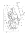
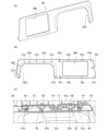
- FIG. 1 is a perspective view showing a vehicle display device provided on an instrument panel.
- FIG. 2 is an exploded perspective view showing the vehicle display device and an attachment mechanism.
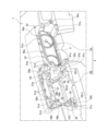
- FIG. 3 is a perspective view showing the display device mounting portion.
- 4(A) to 4(C) are a front view, a rear view, and a right side view showing the first mounting member.
- 5A and 5B are front and rear perspective views showing the second mounting member.
- 6A and 6B are a front view and a cross-sectional view taken along line AA, showing the overlapping portion.
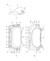
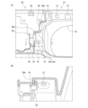
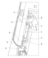
- FIG. 7A is a perspective view showing the second display unit, and FIG. 7B is a side cross-sectional view of the main part showing the manner in which the second display unit is attached.
- FIG. 8(A) and 8(B) are a front perspective view and a rear view showing the third mounting member
- FIG. 8(C) is a plan sectional view of a main portion showing the mounting manner of the third mounting member.
- 9A and 9B are top and bottom perspective views of the fourth mounting member.
- FIG. 10 is a perspective view of a main portion showing a manner in which the fourth mounting member is mounted to the second mounting member.
- FIG. 11 is an exploded perspective view showing a vehicle display device and an attachment mechanism according to another embodiment.
- 12A to 12C are a front perspective view, a rear view, and a rear perspective view of a main part of a second display unit according to another embodiment.
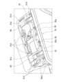
- FIG. 13 is a perspective view of the main part from above, showing a mounting manner of the second display unit according to another embodiment.
- the direction in which the vehicle travels is referred to as "forward,” and the direction in which the vehicle travels backward is referred to as "rearward.”
- the left side of the vehicle's direction of travel is referred to as “left,” and the right side of the vehicle's direction of travel is referred to as “right.”
- the left-right direction and the vehicle width direction are synonymous, and the front-rear direction and the vehicle direction are synonymous.
- FIG. 1 is a perspective view showing a vehicle display device provided in an instrument panel
- Fig. 2 is an exploded perspective view showing the vehicle display device and an attachment mechanism.
- an installation panel 1 is disposed in front of an operator seated in a seat.
- the installation panel 1 is hereinafter referred to as the instrument panel.
- Vehicle display devices 2 and 3 are attached to a display device attachment portion 5 formed in a predetermined position in the left-right direction of the instrument panel 1 via an attachment mechanism 4.
- the vehicle display devices 2, 3 have a first display unit 2 arranged above and in front of a steering wheel (not shown) operated by an operator, and a second display unit 3 arranged on one of the left and right sides of the first display unit 2.
- the second display unit 3 is arranged next to the left side of the first display unit 2.
- the first display unit 2 has a display section 2a consisting of a meter device that displays driving support information related to the vehicle being driven, such as vehicle speed and engine RPM.
- the second display unit 3 has a display section 3a consisting of a liquid crystal panel that displays auxiliary driving support information such as route guidance information. Note that the information displayed on the first display unit 2 and the second display unit 3 is not limited to the above.
- the mounting mechanism 4 has a first mounting member 10 , a second mounting member 20 , a third mounting member 30 , and a fourth mounting member 40 .
- the first mounting member 10 is disposed on the rear side of the first display unit 2 and is a frame-shaped member that covers the outer edge of the display section 2a of the first display unit 2.
- the first mounting member 10 is also called a meter bezel.
- the second mounting member 20 is attached and fixed to the display device mounting section 5 on the front side of the second display unit 3 and is a frame-shaped member through which the second display unit 3 is inserted.
- the second mounting member 20 is also called a back panel.
- the third mounting member 30 is formed to be wide in the left-right direction so as to cover the rear side of the first mounting member 10 and the second mounting member 20.
- the third mounting member 30 is also called a front panel.
- the fourth mounting member 40 is a lid-shaped member that covers the upper rear side of the second display unit 3 and the second mounting member 20.
- the fourth mounting member 40 is also called an upper panel.
- the vehicle display devices 2, 3 can be mounted on the instrument panel 1 by mounting the display device mounting portion 5 in the following order: first display unit 2 ⁇ first mounting member 10 ⁇ second mounting member 20 ⁇ second display unit 3 ⁇ third mounting member 30 ⁇ fourth mounting member 40.
- This configuration can be seen in Fig. 2. Specific configurations of the display device mounting portion 5, the vehicle display devices 2, 3, and the mounting mechanism 4 will be described below.
- Figure 3 is a perspective view showing the display device mounting section.
- a first opening 5A that is long in the front-to-rear direction and into which the first display unit 2 is attached is formed in the right half of the display device mounting section 5.
- a second opening 5B is formed in the left half of the display device mounting section 5, with openings formed on the front and top sides so that the second display unit 3 can be attached.
- the second opening 5B is also divided into a front side and a top side by a left-right opening beam portion 5B1 provided at the top of the front side.
- the display device mounting portion 5 is formed with locking holes 51a, 51b, 51c, and 51d, screw fixing holes 52a, 52b, 52c1, and 52c2, clip fixing hole 53, positioning hole 54, locator pins 55, 55, claw locking portions 56a and 56b, and support piece 57. Please refer to FIG. 3 for this configuration.
- the locking holes 51a, 51b, 51c, 51d are arranged along the outer edge of the first opening 5A, and include first locking holes 51a, 51a, 51a to which the first mounting member 10 is locked; second locking holes 51b, 51b, 51b to which the second mounting member 20 is locked; third locking holes 51c, 51c to which the second mounting member 20 is locked; and fourth locking holes 51d, 51d, 51d, 51d, 51d, 51d, 51d to which the fourth mounting member 40 is locked.
- the screw fixing holes 52a, 52b, 52c1, and 52c2 include first screw fixing holes 52a, 52a, two of which are arranged along the lower outer edge of the first opening 5A, into which the first mounting member 10 is screwed, second screw fixing holes 52b, 52b, two of which are arranged along the outer edge of the second opening 5B, into which the second mounting member 20 is screwed, and unit screw fixing holes 52c1, 52c1, 52c2, 52c2, four of which are arranged on the second opening 5B side, into which the second display unit 3 is screwed.
- the unit screw fixing holes include rear unit screw fixing holes 52c1, 52c1 arranged in a pair on the left and right sides along the outer edge of the second opening 5B, and front unit screw fixing holes 52c2, 52c2 arranged on inclined surfaces 59, 59 located within the second opening 5B and in front of the rear unit screw fixing holes 52c1, 52c1.
- the lower surface of the inclined surfaces 59, 59 in which the front unit screw fixing holes 52c2, 52c2 are formed is supported by a support body 100 extended from a deck cloth (not shown) that extends in the left-right direction and supports the instrument panel 1. This configuration can be seen in Figures 3 and 7(B) .
- the clip fixing holes 53, 53 are arranged in a pair in the left-right direction on the upper edge side of the first opening 5A.
- the upper edge of the first mounting member 10 is flexibly fixed to the clip fixing holes 53, 53 using fixing clips (not shown).
- a pair of positioning holes 54, 54 are arranged on both the left and right ends of the second opening 5B.
- the positioning holes 54, 54 position the second mounting member 20 by inserting the second mounting member 20 through them.
- the locator pins 55, 55 are arranged on the left and right sides of the outer edge of the second opening 5B.
- the locator pins 55, 55 are pin-shaped members that protrude rearward and position the second display unit 3.
- the claw locking portions 56a, 56b are arranged on the left and right sides of the upper edge of the first opening 5A, and include first claw locking portions 56a, 56a to which the third mounting member 30 is locked, and second claw locking portions 56b, 56b to which the fourth mounting member 40 is locked, and a pair are arranged in the front-rear direction on the left end side of the upper edge of the second opening 5B.
- the support pieces 57, 57 are arranged on the left and right sides of the rear surface at the center of the left-right direction of the opening beam portion 5B1.
- the support pieces 57, 57 support the fourth mounting member 40 that is attached to the upper surface of the second opening portion 5B.
- each inclined surface 58, 58 has a back panel fixing hole 58a, 58a formed therein for mounting a second display unit 60 of another embodiment described below.
- the above-mentioned configuration of the mounting portion is one example, and the arrangement and number of the locking holes 51a, 51b, 51c, 51d, screw fixing holes 52a, 52b, 52c1, 52c2, clip fixing hole 53, positioning hole 54, locator pin 55, claw locking portions 56a, 56b, and support pieces 57 are not limited to the above-mentioned configuration and can be changed as appropriate depending on the configuration of the vehicle display device 2, 3 and the mounting mechanism 4.
- the specific configurations of the vehicle display devices 2, 3 and the mounting mechanism 4 will be described in the order in which they are mounted to the display device mounting portion 5.
- the first display unit will be described with reference to FIGS. 1 to 3, the first display unit 2 has a display section 2a capable of displaying a meter on the rear side.
- the first display unit 2 is attached by being fitted into the front end side of the first opening 5A formed in a cylindrical shape in the front-rear direction.
- the display section 2a of the first display unit 2 is disposed in a position further forward than the display section 3a of the second display unit 3.
- Figures 4(A) to 4(C) are a front view, a rear view, and a right side view showing the first mounting member.
- the first mounting member 10 is formed in a frame shape that follows the outer edge of the first display unit 2, with the front side attached to the first opening 5A side and the right half of the third mounting member 30 attached to the rear side.
- the first mounting member 10 has a first locking clip 11 , a first screw hole 12 , a through hole 13 , a first front locking hole 14 , a first front through hole 15 , and a first front claw locking portion 16 .
- the first mounting member 10 has a front-to-rear tubular portion 17 that fits into the first opening 5A, an opening 18 that exposes the display portion 2a of the first display unit 2 by opening the front and rear ends of the tubular portion 17, and a first overlapping portion 19 on the left end side that overlaps with the right end side of the second mounting member 20 when viewed from the front.
- a total of three first locking clips 11, 11, 11 are arranged on the front side of the first mounting member 10, and are respectively locked into the first locking holes 51a, 51a, 51a on the display device mounting section 5 side.
- One first locking clip 11 is provided near the right side of the center of the upper edge of the first mounting member 10, and one is provided on each of the left and right ends of the lower edge of the first mounting member 10. This allows the first mounting member 10 to be temporarily fixed in the mounting position on the first opening 5A side.
- the first screw holes 12, 12 are provided on both the left and right ends of the lower part of the frame-shaped first mounting member 10.
- the lower part of the first mounting member 10 can be attached and fixed to the first opening 5A side by fastening the first screw holes 12, 12 and the screw fixing holes 52a, 52a on the first opening 5A side with fixing screws (not shown).
- the flexibility holes 13, 13 are provided on both the left and right ends of the upper edge of the first mounting member 10. Each flexibility hole 13 is formed as a long hole that is long in the left-right direction. By inserting fixing clips (not shown) through the flexibility holes 13, 13 and the clip fixing holes 53, 53 on the display device mounting section 5 side, the upper part of the first mounting member 10 can be fixed to the first opening 5A side.
- the third mounting member 30 is engaged in the first front engaging holes 14.
- the first front engaging holes 14 are arranged in three on the upper edge of the first mounting member 10 at approximately equal intervals in the left-right direction, with one on each of the left and right ends of the lower part of the first mounting member 10. In other words, a total of five first front engaging holes 14, 14, 14, 14, 14, 14 are formed.
- the first front through holes 15 are arranged in alternating rows in the left-right direction, with the first front locking holes 14 and the first front through holes 15 arranged in a row of three on the upper edge side of the first mounting member 10. In the example shown in the figure, two first front through holes 15, 15 are provided.
- the third mounting member 30 is engaged with the first front claw engagement portion 16.
- the first front claw engagement portion 16 is located on the right end side of the first mounting member 10.
- FIGS. 5(A) and 5(B) are a front view and a rear perspective view showing the second mounting member.
- the second mounting member 20 is formed in a frame shape into which the second display unit 3 can be inserted, with its front side attached to the second opening 5B side and the left half of the third mounting member 30 attached to its rear side.
- the second mounting member 20 has a second locking clip 21, a second screw hole 22, a locator pin 23, a second front locking hole 24, a second front through hole 25, a second front claw locking portion 26, a rib 27, and an upper locking hole 28.
- a second overlapping portion 29 is formed on the right end side of the second mounting member 20 so as to overlap the first overlapping portion 19 of the first mounting member 10 in a front view.
- a total of four second locking clips 21, 21, 21, 21 are arranged on the front side of the second mounting member 20, and are respectively locked into the second locking holes 51b, 51b, 51b, 51b on the second opening 5B side.
- Two second locking clips 21 are arranged side by side on the upper right end side of the second mounting member 20, one is provided on the lower right end side of the second mounting member 20, and one is provided on the left end side of the middle part in the vertical direction of the second mounting member 20. This allows the second locking clips 21, 21, 21 to temporarily secure the second mounting member 20 at the mounting position on the second opening 5B side. This configuration can be seen in FIG. 5(B).
- the locator pins 23, 23 are pin-shaped members that protrude forward from the front surface of the second mounting member 20, and are inserted into the positioning holes 54, 54 on the second opening 5B side. Two locator pins 23, 23 are positioned, one on the upper right side and one on the lower left side. This allows the locator pins 23, 23 to smoothly guide the second mounting member 20 toward the mounting position of the second opening 5B.
- the second screw holes 22, 22 are provided in a pair on the upper and lower sides on the left end side of the frame-shaped second mounting member 20.
- the second mounting member 20 can be attached and fixed to the second opening 5B side by fastening the second screw holes 22, 22 to the screw fixing holes 52b, 52b on the display device mounting part 5 side with fixing screws (not shown).
- the third mounting member 30 is engaged in the second front engaging holes 24.
- Four second front engaging holes 24 are arranged in the left-right direction at approximately equal intervals on the upper edge of the second mounting member 20, and one is provided on the left end side of the middle part of the second mounting member 20 in the up-down direction. In other words, a total of five second front engaging holes 24, 24, 24, 24, 24 are formed.
- a part of the third mounting member 30 is inserted into the second front through-hole 25.
- the second front through-holes 25, 25 are provided at both the left and right ends of the lower end of the second mounting member 20.
- the third mounting member 30 is engaged with the second front claw engagement parts 26.
- the second front claw engagement parts 26, 26 are provided on the left and right sides at the center of the lower end of the second mounting member 20.
- Figure 6(A) is a front view showing the overlapping parts
- Figure 6(B) is a cross-sectional view taken along line A-A in Figure 6(A).
- the first overlapping portion 19 is an L-shaped first bent portion formed by bending the edge of the left end of the first mounting member 10 substantially vertically toward the rear.
- the first overlapping portion 19 extends in the up-down direction along the left end side of the first mounting member 10.
- the edge of the left end of the first mounting member 10 is formed in a crank shape from the upper end side downward, thereby forming a step portion 10a that becomes wider toward the left and right outside.
- two step portions 10a are provided in the vertical direction.
- the first overlapping portion 19 extending in the vertical direction is formed in a crank shape, thereby providing two step portions 19a, 19a. This configuration may be seen in FIG. 6(A).
- the second overlapping portion 29 is a second bent portion formed to bend forward in an L-shape.
- the second overlapping portion 29 is formed in a claw shape that meshes with the first overlapping portion 19 from the rear side.
- the second overlapping portion 29 is disposed so as to overlap with the first overlapping portion 19 when viewed from the seat side.
- the right edge of the second mounting member 20 is formed with steps 20a, 20a that conform to the steps 10a, 10a of the first mounting member 10.
- the right edge of the mounting member 20 is formed with steps 20a, 20a that narrow from the top downward and toward the left and right inward. Accordingly, two second overlapping portions 29 are provided on the right edge of the second mounting member 20, offset in the up-down and left-right directions.
- the second overlapping portion 29 is formed in a U-shape that is open toward the front in a plan view at the edge of the right end of the second mounting member 20, thereby forming a groove 29a into which the first overlapping portion 19 engages. This configuration can be seen in FIG. 6B.
- first overlapping portion 19 and the second overlapping portion 29 have a spigot structure that engages the left end side of the first mounting member 10 with the right end side of the second mounting member 20. This makes it possible to restrict the left-right movement of the second mounting member 20 engaged with the first mounting member 10.
- the vertical ends of the second overlapping portions 29, 29 abut against the step portion 10a of the engaged first mounting member 10, thereby restricting the vertical movement of the second mounting member 20. This configuration can be seen in FIG. 6 (B).
- the installation position of the second mounting member 20 can be smoothly and easily determined. Also, rattling between the first mounting member 10 and the second mounting member 20 arranged side by side is suppressed, and the first display unit 2 and the second display unit 3 can be fixed more firmly to the instrument panel 1 side.
- two claw-shaped second overlapping portions 29 are provided, one above the other, but three or more may be provided, or one second overlapping portion 29 may extend in the vertical direction along the first overlapping portion 19.
- Figure 7(A) is a perspective view showing the second display unit
- Figure 7(B) is a side cross-sectional view of the main part showing the mounting state of the second display unit.
- the second display unit 3 has a display section 3a which is an LCD display section, a box-shaped storage section 6 provided in front of the display section 3a in which a control section is housed, and a pair of mounting pieces 7, 7 attached and fixed to both the left and right ends of the storage section 6.
- the mounting pieces 7, 7 are plate-shaped members in the front-rear direction attached along the side of the storage section 6, and have a first mounting surface 7a with its rear end bent outward to the left and right, and a second mounting surface 7b with its front end bent outward to the left and right.
- the first mounting surface 7a has a flat surface along the display unit 3a, and is formed with unit-side positioning holes 8 into which locator pins 55 on the display device mounting unit 5 are fitted.
- unit fixing holes 9 are formed on the first mounting surface 7a on the left and right outer sides of the unit-side positioning holes 8.
- the second mounting surface 7b has unit fixing holes 9 formed therein, similar to the first mounting surface 7a. This configuration can be seen in FIG.
- Figures 8(A) and 8(B) are a front perspective view and a rear view showing the third mounting member
- Figure 8(C) is a plan sectional view of the main part showing the mounting manner of the third mounting member.
- the third attachment member 30 is formed to be wide in the left-right direction so as to cover the rear sides of the first attachment member 10 and the second attachment member 20.
- the third attachment member 30 has a right half portion which is a first portion surrounding the outer edge of the first display unit 2, and a left half portion which is a second portion covering the rear side of the second attachment member 20.
- the right half of the third mounting member 30 has a notch 30a cut into an inverted U shape at the bottom so that the display section 2a of the first display unit 2 is exposed.
- the left half of the third mounting member 30 has a rectangular opening 30b so that the display section 3a of the second display unit 3 is fitted into it.
- the right half and the left half of the third mounting member 30 are formed to be flush with each other.
- the third mounting member 30 and the display section 3a arranged in the opening 30b are also configured to be flush with each other.
- FIG. 8(A) Third locking clips 31a, 31b, and 31c and third locking claws 32a, 32b, and 32c are arranged along the outer edge on the front side of the third mounting member 30. This configuration can be seen in FIG. 8B.
- the third locking clips 31a, 31b, and 31c include a third locking clip 31a for the bezel, a third locking clip 31b for the back panel, and a third locking clip 31c for the instrument panel.
- Three third bezel locking clips 31a, 31a, 31a, 31a, 31a, 31a, 31a are arranged along the notch 30a in the right half of the front surface of the third mounting member 30, and are locked into the first front locking holes 14, 14, 14, 14, 14 of the first mounting member 10, respectively.
- Three third back panel retaining clips 31b, 31b, 31b, 31b, 31b, 31b, 31b are arranged in a left-right line on the upper left half of the front surface of the third mounting member 30, and are retained in the second front retaining holes 24, 24, 24, 24, 24 of the second mounting member 20, respectively.
- the third instrument panel retaining clips 31c, 31c are arranged on the left and right sides of the lower left half of the front surface of the third mounting member 30, and are retained in the third retaining holes 51c, 51c of the first opening 5A.
- the third locking claws 32a, 32b, and 32c include a third locking claw 32a for the instrument panel, a third locking claw 32b for the bezel, and a third locking claw 32c for the back panel.
- the third instrument panel locking claws 32a, 32a are arranged on the left and right sides of the upper right half of the front surface of the third mounting member 30, and are locked to the first claw locking portions 56a, 56a on the first opening 5A side.
- the third bezel locking claw 32b is located at the top right end of the front surface of the third mounting member 30 and is locked to the first front claw locking portion 16 of the first mounting member 10.
- the third back panel retaining claws 32c, 32c are arranged in a pair on the left and right sides at the bottom of the left half of the front surface of the third mounting member 30, and are retained by the second front retaining claw retaining portions 26, 26 of the second mounting member 20, respectively.
- the third bezel locking clip 31a, the third instrument panel locking claw 32a, and the third bezel locking claw 32b are arranged in an inverted U-shape along the cutout 30a on the front side of the right half of the third mounting member 30.
- the third bezel locking clip 31a and the third instrument panel locking claw 32a are arranged alternately.
- the third back panel fastening clip 31b, the third instrument panel fastening clip 31c, and the third back panel fastening claw 32c are arranged side by side along the opening 30b on the front side of the left half of the third mounting member 30. This configuration can be seen in FIG. 8(B).
- Figures 9(A), 9(B) and 10 are a top perspective view and a bottom perspective view of the fourth mounting member
- Figure 10 is a perspective view of the main parts showing the manner in which the fourth mounting member is mounted to the second mounting member.
- the fourth mounting member 40 is a plate-like member extending in the front-rear direction so as to straddle the upper end sides of the display device mounting portion 5 and the second mounting member 20.
- the fourth mounting member 40 is a lid-like member that covers the front of the opening beam portion 5B1 of the second opening 5B.
- a side portion 40a is formed on the left end side of the fourth mounting member 40, which is bent downward so as to cover the gap formed between the instrument panel 1 and the second display unit 3.
- the fourth mounting member 40 has fourth locking clips 41a, 41b arranged side by side along the outer edge of the lower surface side, and a fourth locking claw 42 locked along the side surface portion 40a.
- the fourth locking clips 41a, 41b include a fourth locking clip 41a for the instrument panel and a fourth locking clip 41b for the back panel.
- Three fourth instrument panel fastening clips 41a are provided along the front edge of the underside of the fourth mounting member 40, two on each of the left and right ends. That is, in the illustrated example, seven fourth instrument panel fastening clips 41a, 41a, 41a, 41a, 41a, 41a, 41a, 41a, 41a, 41a, 41a, 41a, 41a, 41a are provided along the outer edge of the underside of the fourth mounting member 40, and are fastened to the fourth fastening holes 51d, 51d, 51d, 51d, 51d, 51d, 51d of the second opening 5B, respectively.
- the fourth back panel retaining clips 41b, 41b are arranged in a pair at the rear end center of the underside of the fourth mounting member 40, and are retained in the upper retaining holes 28, 28 formed in the rib 27 of the second mounting member 20. See FIG. 10 for this configuration.
- the fourth locking claws 42, 42 are arranged in a pair along the lower end side of the left end side portion 40a of the lower surface of the fourth mounting member 40, and are each locked to the second locking claw portions 56b, 56b of the second opening 5B.
- each of the above-mentioned locking clips is a locking piece with a pair of barbs that move back and forth or that elastically deform when inserted into each locking hole.
- the above-mentioned locking claw is a locking piece with a single barb that locks into each locking portion, and is thinner and less expensive than the locking clip.
- the fixing clip that is inserted into the flexibility hole 13 and clip fixing hole 53 is a rivet-like fastener with barbs that do not move back and forth.
- the above-mentioned fixing screw is a fastener that is screwed between each component.
- the locking devices and fasteners that attach and fix each component are not limited to the above examples.
- the first attachment member 10 can be temporarily fixed at a predetermined attachment position by engaging the first locking clips 11, 11, 11 with the first locking holes 51a, 51a, 51a on the first opening 5A side. Thereafter, the first screw holes 12, 12 at the lower part of the first mounting member 10 can be firmly attached and fixed to the instrument panel 1 side by fastening the first screw holes 12, 12 at the lower part of the first mounting member 10 to the screw fixing hole 52a on the first opening 5A side with a fixing screw. This allows the first mounting member 10 to be smoothly positioned at the mounting position and fixed to the first opening 5A with the fixing screws.
- the upper part of the first mounting member 10 is secured with a fixing clip to the wide lateral openings 13, 13 and the clip fixing hole 53 on the first opening 5A side. This allows the upper part of the first mounting member 10 to be attached and fixed to the first opening 5A side while leaving some room for deformation.
- the lateral openings 13, 13 may be configured to be wide so that there is some room for the fixing clip not only in the lateral direction but also in the vertical direction.
- the first mounting member 10 Due to its positioning, the upper side of the first mounting member 10 is likely to be exposed to sunlight for long periods of time. For this reason, if the first mounting member 10 is made of a resin material, the first mounting member 10 may undergo thermal deformation. In response to this, the first mounting member 10 has a flexibility hole 13 at its top that can absorb some of the thermal deformation of the upper part of the first mounting member 10, effectively preventing the first mounting member 10 from cracking due to thermal deformation.
- the second mounting member 20 By inserting the locator pins 23, 23 into the positioning holes 54, 54 on the second opening 5B side, the second mounting member 20 can be smoothly guided toward a predetermined mounting position. Thereafter, the second overlapping portion 29 on the right end side of the second mounting member 20 engages with the first overlapping portion 19 on the left end side of the first mounting member 10 using a spigot structure, thereby enabling the second mounting member 20 to be stably held in the mounting position. Thereafter, the second mounting member 20 can be temporarily fixed at a predetermined mounting position by engaging the second locking clips 21, 21, 21, 21 with the second locking holes 51b, 51b, 51b, 51b on the second opening 5B side.
- the second mounting member 20 can be firmly attached and fixed to the instrument panel 1 by fastening the second screw holes 22, 22 arranged in a pair above and below on the left end side of the second mounting member 20 to the screw fixing hole 52b on the first opening 5A side with a fixing screw. This allows the second mounting member 20 to be smoothly and easily positioned at the mounting position and fixed to the second opening 5B with the fixing screws.
- the second display unit 3 By inserting the locator pins 55, 55 into the unit side positioning holes 8, the second display unit 3 can be smoothly guided toward a predetermined mounting position. Thereafter, the second display unit 3 can be attached and fixed to the first mounting surface 7a side on the second opening 5B side by fastening the unit fixing hole 9 on the first mounting surface 7a side and the rear unit screw fixing holes 52c1, 52c1 on the display device mounting portion 5 side with fixing screws. Similarly, the second display unit 3 can be attached and fixed to the second mounting surface 7b side of the second opening 5B by fastening the unit fixing hole 9 on the second mounting surface 7b side to the front unit screw fixing holes 52c2, 52c2 formed on the inclined surface 59 of the second opening 5B on the display device mounting portion 5 side with fixing screws. This allows the second display unit 3 to be smoothly and easily positioned at the mounting position and fixed to the second opening 5B with the fixing screws.
- the right half of the third mounting member 30 can be attached to the first opening 5A side by engaging the five bezel third locking clips 31a arranged on the right half with each of the first front locking holes 14 of the first mounting member 10, engaging the five back panel third locking clips 31b arranged on the left half with each of the second front locking holes 24 of the second mounting member 20, and engaging the pair of instrument panel third locking clips 31c with each of the third locking holes 51c of the first opening 5A.
- the third instrument panel fastening clips 31c, 31c are inserted through the second front through holes 25, 25 of the front second mounting member 20, and are thereby fastened to the third fastening holes 51c, 51c on the second opening 5B side.
- the third mounting member 30 can be mounted on the second opening 5B side by engaging the two third engaging claws 32a for the instrument panel located on the right half with the first claw engaging portions 56a on the first opening 5A side, the third engaging claw 32b for the bezel located on the right end side with the first front claw engaging portion 16 of the first mounting member 10, and the two third engaging claws 32c for the back panel located on the lower end side of the left half with the second front claw engaging portion 26 of the second mounting member 20.
- the third instrument panel engaging claws 32a, 32a are engaged with the first claw engaging portions 56a, 56a of the first opening 5A by being inserted into the first front through holes 15, 15 of the front first mounting member 10. This configuration can be seen in Fig. 8(C).
- the third mounting member 30 can be smoothly attached to the display device mounting section 5 simply by pressing it against the rear surfaces of the first mounting member 10 and the second mounting member 20. At this time, the third mounting member 30 can be attached to the display device mounting section 5 without using fixing screws by using a total of 12 locking clips and a total of 5 locking claws. Furthermore, the third mounting member 30 is engaged not only with the first mounting member 10 and the second mounting member 20 on the front side, but also with the display device mounting portion 5 disposed further forward of the first mounting member 10 and the second mounting member 20. Therefore, the third mounting member 30 can be firmly attached to the instrument panel 1 side only with the third engaging clips 31a, 31b, 31c and the third engaging claws 32a, 32b, 32c.
- the third bezel locking clips 31a attached to the first mounting member 10 side and the third instrument panel locking claws 32a attached to the first opening 5A side are arranged alternately in the left-right direction on the upper edge side of the right half of the third mounting member 30. This allows the third mounting member 30 to be attached to the display device mounting portion 5 side more stably and firmly.
- the fourth mounting member 40 has seven fourth locking clips 41a for the instrument panel that are each locked into the fourth locking holes 51d on the top surface of the second opening 5B, and two fourth locking clips 41b for the back panel that are each locked into the upper locking holes 28, 28 formed in the rib 27 of the second mounting member 20. This allows the fourth mounting member 40 to be smoothly mounted on the upper surface side of the second opening 5B.
- the rib 27 of the second mounting member 20 is supported from below by the support pieces 57, 57 on the second opening 5B side. Therefore, when the fourth back panel fastening clips 41b, 41b are fastened to the upper fastening holes 28, 28, the fourth mounting member 40 can restrict the rib 27 from bending downward. In other words, the fourth back panel fastening clips 41b, 41b can be stably fastened to the upper fastening holes 28, 28. This configuration can be seen in FIG. 10.
- the fourth mounting member 40 similarly has fourth locking claws 42 arranged in two positions, front and rear, along the lower end side of the side surface portion 40a, which lock into the second locking portions 56b, 56b of the second opening 5B.
- the third mounting member 30 and the fourth mounting member 40 are connected to the display device mounting part 5 side only with the third locking clips 31a, 31b, 31c, the fourth locking clips 41a, 41b, the third locking claws 32a, 32b, 32c, and the fourth locking claw 42, without using fixing screws.
- the fasteners are not positioned in a position visible to the operator in the seat. This results in a neat and tidy appearance around the vehicle display devices 2, 3.
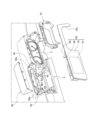
- FIG. 11 is an exploded perspective view showing a vehicle display device and attachment mechanism of another embodiment
- Fig. 12(A) to Fig. 12(C) are a front perspective view, a rear view, and a rear perspective view of the main part of the second display unit of another embodiment
- Fig. 13 is a perspective view from above of the main part showing the attachment mode of the second display unit of another embodiment.
- the vehicle display device and attachment mechanism will be described with respect to differences from the above-mentioned examples.
- the vehicle display device 2 , 60 has a first display unit 2 and a second display unit 60 .
- the mounting mechanism 4 has a first mounting member 10 and a fourth mounting member 40 . According to the mounting mechanism 4, the vehicle display device 2, 60 can be mounted on the instrument panel 1 side by mounting the first display unit 2 ⁇ first mounting member 10 ⁇ second display unit 60 ⁇ fourth mounting member 40 on the display device mounting portion 5 side in that order.
- the second display unit 60 has a display section 61 which is a liquid crystal panel that displays various information, a box-shaped storage section 90 which is disposed in front of the display section 61 and stores the control section, a front panel 70 which extends in the left-right direction so as to flushly cover the rear surface of the display section 61 and the outer edge of the first mounting member 10, and a back panel 80 which covers the front surface of the left half of the front panel 70.
- a display section 61 which is a liquid crystal panel that displays various information
- a box-shaped storage section 90 which is disposed in front of the display section 61 and stores the control section
- a front panel 70 which extends in the left-right direction so as to flushly cover the rear surface of the display section 61 and the outer edge of the first mounting member 10
- a back panel 80 which covers the front surface of the left half of the front panel 70.
- the front panel 70 is a plate-like member extending in the left-right direction so as to cover the entire area from the first opening 5A to the second opening 5B with a flush plane, and a cutout portion 70a is formed in the right half by cutting out the lower end in an inverted U-shape so as to expose the display portion 2a of the first display unit 2.
- a light-transmitting material is used for at least the left half of the front panel 70.
- the front panel 70 is configured so that the display content of the display unit 3a arranged on the front side of the front panel 70 can be seen from behind the front panel 70.
- third locking clips 31a, 31a, 31a, 31a, 31a, 31a for the bezel, third locking claws 32a, 32a for the instrument panel, and third locking claws 32b for the bezel are arranged in a row along the cutout portion 70a.
- the third bezel clip 31a, the third instrument panel claw 32a, and the third bezel claw 32b are arranged in an inverted U-shape along the notch 70a.
- the third bezel clip 31a and the third instrument panel claw 32a are arranged alternately on the upper edge side extending in the left-right direction. This configuration can be seen in FIG. 12B.
- a back panel 80 is fixed integrally to the left half of the front surface of the front panel 70 .
- the back panel 80 covers the left half of the front surface of the front panel 70 so as to surround the storage section 90.
- the back panel 80 is fixed integrally to the front surface side of the front panel 70, and the display section 61 is stored between the back panel 80 and the front panel 70.
- Upper mounting pieces 81, 81 and locking protrusions 82, 82 are provided on the front side of the back panel 80.
- the back panel 80 is a metal member formed by die casting, and the upper mounting pieces 81, 81 and the locking protrusions 82, 82 are also integrally formed.
- the upper mounting pieces 81, 81 are attached and fixed to the inclined surfaces 58, 58 formed on both the left and right ends of the opening beam portion 5B1.
- the upper mounting pieces 81, 81 are plate-shaped members extending forward from the top of the front surface of the back panel 80, and are provided in pairs on both the left and right ends.
- Mounting piece fixing holes 81a, 81a are formed on the front end sides of the pair of upper mounting pieces 81, 81 for fixing to the inclined surfaces 58 on the opening beam portion 5B1 side.
- a pair of locking projections 82 are provided on the left and right inside the pair of left and right upper mounting pieces 81, 81.
- the locking projections 82 have upper locking holes 82a, 82a in the vertical direction to which the fourth mounting member 40 is locked. Please refer to Figures 12(B) and 13 for this configuration.
- the accommodation portion 90 has a pair of lower mounting pieces 91, 91 fixed to both left and right ends.
- the lower mounting piece 91 has a front end that is bent outward in the left-right direction to form a mounting surface 92.
- the mounting surface 92 is formed with unit fixing holes 93 for screwing the accommodation portion 90 to the inclined surfaces 59, 59 on the second opening 5B side. This configuration can be seen in FIG. 12C.
- the right half of the second display unit 60 can be attached and fixed to the first opening 5A side by engaging the third bezel locking clip 31a with the first front locking hole 14 of the first mounting member 10, engaging the third instrument panel locking claw 32a with the first claw locking portion 56a on the first opening 5A side, and engaging the third bezel locking claw 32b with the first front claw locking portion 16 of the first mounting member 10.
- the upper mounting piece 81 can be fixed to the inclined surfaces 58, 58 on the opening beam portion 5B1 side by fastening the mounting piece fixing hole 81a of the upper mounting piece 81 to the back panel fixing holes 58a, 58a formed in the inclined surface 58 with a fixing screw (not shown).
- a fixing screw not shown
- This configuration can be seen in Figures 12(A) and 13.
- the unit fixing holes 93, 93 of the lower mounting pieces 91, 91 to the front unit screw fixing holes 52c2, 52c2 on the second opening 5B side with fixing screws, the lower part of the back panel 80 can be fixed to the inclined surfaces 59, 59 on the second opening 5B side. This allows the left half of the second display unit 60 to be fixed to the second opening 5B side.
- the upper mounting piece 81 and the lower mounting piece 91 are attached to the second opening 5B and the respective inclined surfaces 58, 59 on the opening beam portion 5B1 side by fixing screws that are screwed in the vertical direction, the installation work of the left half of the second display unit 60 to the second opening 5B can be performed from the top side of the second opening 5B. Furthermore, since the fixing screws can be arranged in positions that are not visible to the operator seated in the seat, the appearance of the vehicle display device 2, 60 mounted on the instrument panel 1 can be kept clean.
- the support pieces 57 formed on the opening beam portion 5B1 may be arranged on both the left and right sides of the locking protrusions 82, so that the support pieces 57 function as positioning members for positioning the second display unit 60 in a predetermined position.
- the fourth mounting member 40 has seven fourth locking clips 41a for the instrument panel that are each locked into the fourth locking holes 51d on the top surface of the second opening 5B, and two fourth locking clips 41b for the back panel that are locked into the upper locking holes 82a, 82a formed in the locking protrusion 82.
- the fourth mounting member 40 has fourth locking claws 42 arranged at two positions, front and rear, along the lower end side of the side surface portion 40a, which are locked to the second claw locking portions 56b, 56b of the second opening 5B.
- the above-mentioned configuration allows the display device mounting portion 5 formed on the instrument panel 1 to be mounted with either a vehicle display device 2, 60 having a second display unit 60 in which the front panel 70 and back panel 80 are integrally molded, or a vehicle display device 2, 3 including a second display unit 3 in which the third mounting member 30 and second mounting member 20, which correspond to the front panel 70 and back panel 80, are separately constructed, providing high versatility.
- the vehicle display devices 2, 3, 60 are formed such that the front panel, which extends from the left-right center to the right end of the instrument panel 1 that extends in the left-right direction, has a first portion that surrounds the outer edge of the first display portion located in a recessed position forward of the right half of the front panel, and a second portion where the second display portion located in the left half of the front panel is displayed, are flush with each other. Furthermore, the vehicle display devices 2, 3, 60 are attached so that the fixing device between them and the display device mounting portion 5 is not visible. This results in a clean appearance for the vehicle display devices 2, 3, 60 provided on the instrument panel 1.
- the vehicle display devices 2, 3 may be arranged symmetrically depending on the position of the driver's seat.
- the present invention is not limited to the above-described embodiment, and can be modified or improved as appropriate.
- a mounting structure for a vehicle display device in which a vehicle display device that displays information about a vehicle is mounted to a mounting portion provided on an installation panel extending in a vehicle width direction, comprising:
- the vehicle display device includes a first display unit arranged on one side of the mounting portion in a vehicle width direction, and a second display unit arranged on the other side of the mounting portion in the vehicle width direction,
- An upper attachment piece is provided on an upper portion of the second display unit, the upper attachment piece extending forward.
- the upper mounting piece is placed on a mounting portion formed on the mounting part, and is attached and fixed to the mounting portion by a fastener inserted in the vertical direction.
- the second display unit is attached and fixed to the mounting part side by the fastener inserted in the vertical direction, so that it is easy to secure space for the attachment work of the second display unit to the mounting part side, and the attachment work and maintenance are easy. Also, since the fastener is arranged on the front side of the display part of the second display unit and cannot be seen from the seat side, the appearance is also neat.
- the second display unit is a front panel extending in a vehicle width direction from the other vehicle width direction side of the mounting portion so as to cover a rear side of an outer edge of the first display unit; a control unit provided on a rear surface of the front panel on the other side in the vehicle width direction, the control unit causing the front panel to display information about the vehicle; a back panel provided to cover a rear surface of the front panel on the other side in the vehicle width direction so as to surround the control unit,
- the upper mounting piece is provided on the upper portion of the back panel.
- a housing in which the control unit is housed is provided with a lower mounting piece,
- the lower mounting piece is placed on the upper surface of a support extending upward from a deck cross in the vehicle width direction that supports the installation panel, and is fixed to the support by a fastener inserted in the vertical direction.
- a mounting structure for a vehicle display device According to this configuration, the second display unit can be supported directly on the deck crossing, so that it can be stably attached to the mounting portion using only vertical fixing devices.
- a meter bezel is provided, the meter bezel being formed in a cylindrical shape along an outer edge of the first display unit and being connected to the mounting portion while being disposed behind the first display unit, An accommodation mechanism is provided on an upper portion of the meter bezel to allow the meter bezel to be displaced.
- the mounting structure for a vehicle display device according to any one of (1) to (3). According to this configuration, even if the upper part of the meter bezel, which is relatively prone to being exposed to direct sunlight, is deformed by heat, the displacement can be absorbed by the flexibility mechanism, and damage to the meter bezel can be prevented.
- the adapting mechanism has an elongated hole formed in an upper portion of the meter bezel, and a fastener for fastening the upper portion of the meter bezel to the mounting portion via the elongated hole,
- the long hole is formed wide at least in the vehicle width direction.
- a lower portion of the meter bezel is fixed to the mounting portion by using a fastener that is screwed into the mounting portion.
- a first connecting portion connected to the meter bezel side, a second connecting portion connected to the back panel side, and a third connecting portion connected to the mounting portion side are provided on a front surface side of the front panel, the first connecting portion being extended forward.
- the mounting structure for a vehicle display device according to any one of (2) to (6). According to this configuration, the front panel can be fixed not only to the mounting portion but also to the meter bezel and the back panel, thereby improving the rigidity of the front panel.
- the first connecting portion and the third connecting portion are arranged alternately in a vehicle width direction.
- a mounting structure for a vehicle display device according to (7) With this configuration, the rigidity of the front panel, which is formed in a frame shape along the outer edge of the first display unit, is further improved.
- a plate-shaped upper panel is provided to be fixed to an upper portion of the mounting portion and an upper portion of the back panel so as to straddle the mounting portion and the back panel.
- the mounting structure for a vehicle display device according to any one of (2) to (8). According to this configuration, the upper panel can connect and fix the mounting portion and the back panel, thereby improving the overall rigidity of the vehicle display device.
- An extension portion extending forward is provided on the upper end side of the back panel, A locking piece is provided at the rear end of the upper panel to lock the back panel via the extension portion.
- a mounting structure for a display device for a vehicle According to this configuration, the connecting portion between the upper panel and the back panel is not visible, resulting in a neat finish.
- the extension portion is formed with a locking hole into which the locking piece of the upper panel is pushed and locked.
- a support piece that supports the extension part from below is provided on the mounting part.
- a vehicle display device provided on an installation panel extending in a vehicle width direction, A front panel extending from a center side to one end side of the installation panel in a vehicle width direction; a first display unit disposed on one side of the front panel in a vehicle width direction and at a predetermined position further forward than the front panel; a second display unit disposed on the other side of the front panel in the vehicle width direction, the front panel has a first portion surrounding an outer edge of the first display portion on one side in a vehicle width direction, and a second portion into which the second display portion is inserted on the other side in the vehicle width direction, The first portion and the second portion are formed to be flush with each other.
- Vehicle display device provided on an installation panel extending in a vehicle width direction, A front panel extending from a center side to one end side of the installation panel in a vehicle width direction; a first display unit disposed on one side of the front panel in a vehicle width direction and at a predetermined position further forward than the front panel; a second display unit disposed on the other side
- the sense of unity between the first display portion and the second display portion arranged side by side in the vehicle width direction is increased, so that the overall appearance of the vehicle display device is neat and the finish is neat. Also, since the front panel is extended in the vehicle width direction from the second portion including the second display portion to the first portion surrounding the outer edge of the first display portion in a flush plane, it is easy to feel that the area in which information is displayed by the vehicle display device is wider.
- the first portion formed along an outer edge of the first display portion is formed in a U-shape with an open lower end side.
Landscapes
- Engineering & Computer Science (AREA)
- Chemical & Material Sciences (AREA)
- Combustion & Propulsion (AREA)
- Transportation (AREA)
- Mechanical Engineering (AREA)
- Instrument Panels (AREA)
Abstract
車幅方向に延在するインストールメントパネルに設けられた取付部に、車両に関する情報を表示する車両用表示装置を取付ける車両用表示装置の取付構造であって、車両用表示装置は、取付部の車幅方向一方側に配置される第1表示ユニットと、取付部の車幅方向他方側に配置される第2表示ユニットと、を有し、第2表示ユニットの上部には、前方に向かって延設された上側取付片が設けられ、上側取付片は、取付部に形成された載置部に載置され、上下方向に挿通される固定具によって、載置部に取付固定される。
Description
本発明は、インストールメントパネルに取付けられる車両用表示装置、及び車両用表示装置の取付構造に関する。
運転者が着座する座席の前方に配置されるインストールメントパネルに、車両の速度や、エンジンの回転数等の車両に関する運転支援情報を表示するメータユニットと、経路誘導情報のような付加的な運転支援情報を表示するナビゲーション装置と、が設けられた車両が従来から知られている。
例えば、特許文献1には、座席の前方に設けられるメータユニットと、メータユニットの上方に配置されるヘッドアップディスプレイと、が上下に並べて配置されることにより、運転者が運転中に視線を落とすことなく運転支援情報をスムーズに確認できる車両用情報表示装置と、車両用情報方表示装置の取付構造が開示されている。
上記特許文献1では、ヘッドアップディスプレイを前後方向に挿通される固定ねじによってメータユニット側の枠体に固定することによってメータユニット及びヘッドアップディスプレイをユニット化されている。ユニット化されたメータユニット及びヘッドアップディスプレイは、インパネ側の嵌合孔に挿通される前後方向のピンと、前後方向に挿通される固定ねじと、によってインパネ側に嵌め込むようにして固定されている。
このため、メータユニット及びヘッドアップディスプレイを固定ねじでインパネ側に締結する固定作業をするスペースが確保し難く、取付作業に手間が掛かる。また、ヘッドアップディスプレイのみを取り外すこともできないため、メンテナンスにも手間が掛かる。また、固定ねじを隠すためのメータフードも別途に取付ける必要もあるため、部品点数も多くなってコストも高くなるという課題がある。
本発明は、このような状況に鑑みてなされたものであり、第2表示ユニットの取付部側への取付作業や、第2表示部のメンテナンス作業が容易で、見た目の仕上がりもきれいになる車両用表示装置の取付構造を提供することを目的とする。
本発明の上記目的は、下記の構成により達成される。
[1] 車幅方向に延在するインストールメントパネルに設けられた取付部に、車両に関する情報を表示する車両用表示装置を取付ける車両用表示装置の取付構造であって、
前記車両用表示装置は、前記取付部の車幅方向一方側に配置される第1表示ユニットと、前記取付部の車幅方向他方側に配置される第2表示ユニットと、を有し、
前記第2表示ユニットの上部には、前方に向かって延設された上側取付片が設けられ、
前記上側取付片は、前記取付部に形成された載置部に載置され、上下方向に挿通される固定具によって、前記載置部に取付固定される、
車両用表示装置の取付構造。
[2] 前記第2表示ユニットは、
前記取付部の車幅方向他方側から前記第1表示ユニットの外縁の後側を覆うように車幅方向に延設されたフロントパネルと、
前記フロントパネルの車幅方向他方側の背面に設けられ、前記車両に関する情報を前記フロントパネルに表示させる制御部と、
前記制御部を取り囲むように前記フロントパネルの車幅方向他方側の背面を覆うように設けられたバックパネルと、を有し、
前記バックパネルの上部には、前記上側取付片が設けられた、
[1]に記載の車両用表示装置の取付構造。
[3] 前記制御部が収容された収容体には、下側取付片が設けられ、
前記下側取付片は、前記インストールメントパネルを支持する車幅方向のデッキクロスから上側に延設された支持体の上面に載置され、上下方向に挿通される固定具によって、前記支持体に固定される、
[2]に記載の車両用表示装置の取付構造。
[4] 前記第1表示ユニットの外縁に沿った筒状に形成され、前記第1表示ユニットの後側に配置された状態で前記取付部に連結されるメータベゼルを設け、
前記メータベゼルの上部に、前記メータベゼルの変位を許容する融通機構を設けた、
[1]に記載の車両用表示装置の取付構造。
[5] 前記融通機構は、前記メータベゼルの上部に形成された長孔と、前記長孔を介して前記メータベゼルの上部を前記取付部に係止するための係止具と、を有し、
前記長孔は、少なくとも車幅方向に幅広に形成された、
[4]に記載の車両用表示装置の取付構造。
[6] 前記メータベゼルの下部は、前記取付部に螺合される固定具を用いて前記取付部に固定された、
[4]又は[5]に記載の車両用表示装置の取付構造。
[7] 前記フロントパネルの前面側には、前記メータベゼル側に連結される第1連結部と、前記バックパネル側に連結される第2連結部と、前記取付部側に連結される第3連結部と、が前方に向けて延設された、
[2]に記載の車両用表示装置の取付構造。
[8] 前記第1連結部と、前記第3連結部とが、車幅方向に交互に並べて配置された、
[7]に記載の車両用表示装置の取付構造。
[9] 前記取付部及び前記バックパネルに跨るように、前記取付部の上部と、前記バックパネルの上部とに固定される板状のアッパーパネルを設けた、
[2]に記載の車両用表示装置の取付構造。
[10] 前記バックパネルの上端側には、前方に向かって延在する延在部が設けられ、
前記アッパーパネルの後端部には、前記延在部を介して前記バックパネルを係止する係止片が設けられた、
[9]に記載の車両用表示装置の取付構造。
[11] 前記延在部には、前記アッパーパネルの係止片が押込まれることにより係止される係止孔が形成された、
[10]に記載の車両用表示装置の取付構造。
[12] 前記取付部に前記延在部を下支えする支持片を設けた、
[10]に記載の車両用表示装置の取付構造。
[13] 車幅方向に延在するインストールメントパネルに設けられた車両用表示装置であって、
前記インストールメントパネルの車幅方向の中央側から一端側まで延在するフロントパネルと、
前記フロントパネルの車幅方向一方側で且つ、前記フロントパネルより前方に奥まった所定位置に配置された第1表示部と、
前記フロントパネルの車幅方向他方側に配置された第2表示部と、を備え、
前記フロントパネルは、車幅方向一方側で前記第1表示部の外縁を囲繞する第1部分と、車幅方向他方側で前記第2表示部が内挿された第2部分と、を有し、
前記第1部分及び前記第2部分が面一となるように形成された、
車両用表示装置。
[14] 前記第1表示部の外縁に沿って形成される前記第1部分を、下端側が開放されたU字状に形成した、
[13]に記載の車両用表示装置。
[1] 車幅方向に延在するインストールメントパネルに設けられた取付部に、車両に関する情報を表示する車両用表示装置を取付ける車両用表示装置の取付構造であって、
前記車両用表示装置は、前記取付部の車幅方向一方側に配置される第1表示ユニットと、前記取付部の車幅方向他方側に配置される第2表示ユニットと、を有し、
前記第2表示ユニットの上部には、前方に向かって延設された上側取付片が設けられ、
前記上側取付片は、前記取付部に形成された載置部に載置され、上下方向に挿通される固定具によって、前記載置部に取付固定される、
車両用表示装置の取付構造。
[2] 前記第2表示ユニットは、
前記取付部の車幅方向他方側から前記第1表示ユニットの外縁の後側を覆うように車幅方向に延設されたフロントパネルと、
前記フロントパネルの車幅方向他方側の背面に設けられ、前記車両に関する情報を前記フロントパネルに表示させる制御部と、
前記制御部を取り囲むように前記フロントパネルの車幅方向他方側の背面を覆うように設けられたバックパネルと、を有し、
前記バックパネルの上部には、前記上側取付片が設けられた、
[1]に記載の車両用表示装置の取付構造。
[3] 前記制御部が収容された収容体には、下側取付片が設けられ、
前記下側取付片は、前記インストールメントパネルを支持する車幅方向のデッキクロスから上側に延設された支持体の上面に載置され、上下方向に挿通される固定具によって、前記支持体に固定される、
[2]に記載の車両用表示装置の取付構造。
[4] 前記第1表示ユニットの外縁に沿った筒状に形成され、前記第1表示ユニットの後側に配置された状態で前記取付部に連結されるメータベゼルを設け、
前記メータベゼルの上部に、前記メータベゼルの変位を許容する融通機構を設けた、
[1]に記載の車両用表示装置の取付構造。
[5] 前記融通機構は、前記メータベゼルの上部に形成された長孔と、前記長孔を介して前記メータベゼルの上部を前記取付部に係止するための係止具と、を有し、
前記長孔は、少なくとも車幅方向に幅広に形成された、
[4]に記載の車両用表示装置の取付構造。
[6] 前記メータベゼルの下部は、前記取付部に螺合される固定具を用いて前記取付部に固定された、
[4]又は[5]に記載の車両用表示装置の取付構造。
[7] 前記フロントパネルの前面側には、前記メータベゼル側に連結される第1連結部と、前記バックパネル側に連結される第2連結部と、前記取付部側に連結される第3連結部と、が前方に向けて延設された、
[2]に記載の車両用表示装置の取付構造。
[8] 前記第1連結部と、前記第3連結部とが、車幅方向に交互に並べて配置された、
[7]に記載の車両用表示装置の取付構造。
[9] 前記取付部及び前記バックパネルに跨るように、前記取付部の上部と、前記バックパネルの上部とに固定される板状のアッパーパネルを設けた、
[2]に記載の車両用表示装置の取付構造。
[10] 前記バックパネルの上端側には、前方に向かって延在する延在部が設けられ、
前記アッパーパネルの後端部には、前記延在部を介して前記バックパネルを係止する係止片が設けられた、
[9]に記載の車両用表示装置の取付構造。
[11] 前記延在部には、前記アッパーパネルの係止片が押込まれることにより係止される係止孔が形成された、
[10]に記載の車両用表示装置の取付構造。
[12] 前記取付部に前記延在部を下支えする支持片を設けた、
[10]に記載の車両用表示装置の取付構造。
[13] 車幅方向に延在するインストールメントパネルに設けられた車両用表示装置であって、
前記インストールメントパネルの車幅方向の中央側から一端側まで延在するフロントパネルと、
前記フロントパネルの車幅方向一方側で且つ、前記フロントパネルより前方に奥まった所定位置に配置された第1表示部と、
前記フロントパネルの車幅方向他方側に配置された第2表示部と、を備え、
前記フロントパネルは、車幅方向一方側で前記第1表示部の外縁を囲繞する第1部分と、車幅方向他方側で前記第2表示部が内挿された第2部分と、を有し、
前記第1部分及び前記第2部分が面一となるように形成された、
車両用表示装置。
[14] 前記第1表示部の外縁に沿って形成される前記第1部分を、下端側が開放されたU字状に形成した、
[13]に記載の車両用表示装置。
本発明によれば、第2表示ユニットを、上下方向に挿通される固定具によって取付部側に取付固定したことにより、第2表示ユニットの取付部側への取付作業をするスペースが確保し易いため、取付作業や、メンテナンスが容易になる。また、固定具が第2表示ユニットの表示部の前方側に配置されて、座席側から見えなくなるため、見た目の仕上がりもきれいになる。
以下、本発明の一実施形態に係る車両用表示装置の取付構造について、図面を参照して説明する。また、本実施形態は本発明の一例を示したものであって、本発明は本実施形態に限定されるものではない。また、本実施形態には種々の変更又は改良を加えることが可能であり、その様な変更又は改良を加えた形態も本発明に含まれ得る。
本実施例において、車両の進行方向を「前」、車両の後進方向を「後」と称する。車両の進行方向左側を「左」、車両の進行方向右側を「右」と称する。また、左右方向と、車幅方向とは同義であり、前後方向と、車両方向とは同義である。
(全体構成)
図1は、インパネに設けた車両用表示装置を示した斜視図であり、図2は、車両用表示装置と、取付機構とを示した分解斜視図である。乗用自動車等からなる車両は、座席に着座したオペレータの前方にインストールメントパネル1が配置される。インストールメントパネル1を、以下インパネと称する。インパネ1には、左右方向の所定位置に形成された表示装置取付部5に、取付機構4を介して、車両用表示装置2、3が取付けられている。
図1は、インパネに設けた車両用表示装置を示した斜視図であり、図2は、車両用表示装置と、取付機構とを示した分解斜視図である。乗用自動車等からなる車両は、座席に着座したオペレータの前方にインストールメントパネル1が配置される。インストールメントパネル1を、以下インパネと称する。インパネ1には、左右方向の所定位置に形成された表示装置取付部5に、取付機構4を介して、車両用表示装置2、3が取付けられている。
車両用表示装置2、3は、オペレータが操作する図示しないステアリングハンドルの前方上側に配置される第1表示ユニット2と、第1表示ユニット2の左右一方側に配置される第2表示ユニット3と、を有する。図示する例では、第2表示ユニット3は、第1表示ユニット2の左側に並べて配置されている。第1表示ユニット2は、車速やエンジン回転数等、運転中の車両に関する運転支援情報が表示されるメータ機器からなる表示部2aを有する。第2表示ユニット3は、経路誘導情報のような補助的な運転支援情報が表示される液晶パネルからなる表示部3aを有する。なお、第1表示ユニット2及び第2表示ユニット3に表示される情報は上記には限られない。
取付機構4は、第1取付部材10と、第2取付部材20と、第3取付部材30と、第4取付部材40と、を有する。
第1取付部材10は、第1表示ユニット2の後側に配置され、第1表示ユニット2の表示部2a外縁を覆う枠状部材である。第1取付部材10は、メータベゼルとも称す。第2取付部材20は、第2表示ユニット3の前側で表示装置取付部5に取付固定され、第2表示ユニット3が挿通される枠状部材である。第2取付部材20は、バックパネルとも称する。第3取付部材30は、第1取付部材10及び第2取付部材20の後面側を覆うように左右方向に幅広に形成されている。第3取付部材30は、フロントパネルとも称する。第4取付部材40は、第2表示ユニット3及び第2取付部材20の上方後側を覆う蓋状部材である。第4取付部材40は、アッパーパネルとも称する。
取付機構4によれば、第1表示ユニット2→第1取付部材10→第2取付部材20→第2表示ユニット3→第3取付部材30→第4取付部材40の順番で、表示装置取付部5側に取付けることにより、車両用表示装置2、3をインパネ1側に取付けることができる。この構成は、図2を参照するとよい。以下、表示装置取付部5、車両用表示装置2、3、取付機構4の具体的な構成について説明する。
第1取付部材10は、第1表示ユニット2の後側に配置され、第1表示ユニット2の表示部2a外縁を覆う枠状部材である。第1取付部材10は、メータベゼルとも称す。第2取付部材20は、第2表示ユニット3の前側で表示装置取付部5に取付固定され、第2表示ユニット3が挿通される枠状部材である。第2取付部材20は、バックパネルとも称する。第3取付部材30は、第1取付部材10及び第2取付部材20の後面側を覆うように左右方向に幅広に形成されている。第3取付部材30は、フロントパネルとも称する。第4取付部材40は、第2表示ユニット3及び第2取付部材20の上方後側を覆う蓋状部材である。第4取付部材40は、アッパーパネルとも称する。
取付機構4によれば、第1表示ユニット2→第1取付部材10→第2取付部材20→第2表示ユニット3→第3取付部材30→第4取付部材40の順番で、表示装置取付部5側に取付けることにより、車両用表示装置2、3をインパネ1側に取付けることができる。この構成は、図2を参照するとよい。以下、表示装置取付部5、車両用表示装置2、3、取付機構4の具体的な構成について説明する。
図3に基づいて、表示装置取付部5の具体的な構成について説明する。図3は、表示装置取付部を示した斜視図である。表示装置取付部5の右側半部には、第1表示ユニット2が取付けられる前後方向に長い筒状の第1開口部5Aが形成される。表示装置取付部5の左側半部には、第2表示ユニット3が取付られるように正面及び上面を開口形成した第2開口部5Bが形成されている。また、第2開口部5Bは、正面上部に設けられた左右方向の開口梁部5B1によって、正面側と上面側とが区画されている。
表示装置取付部5には、係止孔51a、51b、51c、51dと、ねじ固定孔52a、52b、52c1、52c2と、クリップ固定孔53と、位置決め孔54と、ロケーターピン55、55と、爪係止部56a、56bと、支持片57と、が形成されている。この構成は、図3を参照するとよい。
係止孔51a、51b、51c、51dは、第1開口部5Aの外縁に沿って3つ配置され、第1取付部材10が係止される第1係止孔51a、51a、51aと、第2開口部5Bの外縁の正面側に4つ配置され、第2取付部材20が係止される第2係止孔51b、51b、51b、51bと、第2開口部5Bの下部左右両端側に2つ配置され、第2取付部材20が係止される第3係止孔51c、51cと、第2開口部5B上面の外縁に沿って7つ配置され、第4取付部材40が係止される第4係止孔51d、51d、51d、51d、51d、51d、51dと、を有する。
ねじ固定孔52a、52b、52c1、52c2は、第1開口部5Aの外縁下部側に沿って2つ配置され、第1取付部材10がねじ固定される第1ねじ固定孔52a、52aと、第2開口部5Bの外縁に沿って2つ配置され、第2取付部材20がねじ固定される第2ねじ固定孔52b、52bと、第2開口部5B側に4つ配置され、第2表示ユニット3がねじ固定されるユニットねじ固定孔52c1、52c1、52c2、52c2と、を有する。
特に、ユニットねじ固定孔は、第2開口部5Bの外縁に沿って左右一対配置される後ユニットねじ固定孔52c1、52c1と、第2開口部5B内であって後ユニットねじ固定孔52c1、52c1の前方に配置された傾斜面59、59に配置された前ユニットねじ固定孔52c2、52c2と、を有する。
なお、前ユニットねじ固定孔52c2、52c2が形成される傾斜面59、59は、その下面側がインパネ1を支持する左右方向に延在する不図示のデッキクロスから延設された支持体100によって支持されている。この構成は、図3及び図7(B)を参照するとよい。
特に、ユニットねじ固定孔は、第2開口部5Bの外縁に沿って左右一対配置される後ユニットねじ固定孔52c1、52c1と、第2開口部5B内であって後ユニットねじ固定孔52c1、52c1の前方に配置された傾斜面59、59に配置された前ユニットねじ固定孔52c2、52c2と、を有する。
なお、前ユニットねじ固定孔52c2、52c2が形成される傾斜面59、59は、その下面側がインパネ1を支持する左右方向に延在する不図示のデッキクロスから延設された支持体100によって支持されている。この構成は、図3及び図7(B)を参照するとよい。
クリップ固定孔53、53は、第1開口部5Aの上縁側で左右方向に並べて一対配置される。クリップ固定孔53、53には、不図示の固定クリップを用いて、第1取付部材10の上縁が融通可能に固定される。
位置決め孔54、54は、第2開口部5Bの左右両端側に一対配置される。位置決め孔54、54は、第2取付部材20が挿通されることによって第2取付部材20を位置決めする。
ロケーターピン55、55は、第2開口部5Bの外縁側に左右一対配置される。ロケーターピン55、55は、後方に向かって突設されるピン状部材であって、第2表示ユニット3を位置決めする。
爪係止部56a、56bは、第1開口部5Aの上縁側に左右一対配置され、第3取付部材30が係止される第1爪係止部56a、56aと、第2開口部5Bの上縁左端側で前後方向に一対配置され、第4取付部材40が係止される第2爪係止部56b、56bと、を有する。
支持片57、57は、開口梁部5B1の左右方向中央側に後面に左右一対配置されている。支持片57、57は、第2開口部5Bの上面に取付けられる第4取付部材40を下支えする。
なお、開口梁部5B1の左右両端側には、前方上側に向かって傾斜する傾斜面59、59が形成されている。各傾斜面58、58には、後述する別実施例の第2表示ユニット60を取付けるためのバックパネル用固定孔58a、58aが形成されている。
また、上記の取付部を構成は一例であって、係止孔51a、51b、51c、51d、ねじ固定孔52a、52b、52c1、52c2、クリップ固定孔53、位置決め孔54、ロケーターピン55、爪係止部56a、56b、支持片57の配置や数は、上記構成に限られず、車両用表示装置2、3や取付機構4の構成に応じて適宜変更できる。
次に、図1~図10に基づいて、車両用表示装置2、3及び取付機構4の具体的な構成について、表示装置取付部5に取付けられる順番に沿って説明する。まず、図1~図3に基づき、第1表示ユニットについて説明する。
第1表示ユニット2は、図1~図3に示すように、後面側にメータ表示可能な表示部2aを有する。第1表示ユニット2は、前後方向の筒状に形成された第1開口部5Aの前端側に嵌め込まれるようにして取り付けられる。これにより、第1表示ユニット2の表示部2aは、第2表示ユニット3の表示部3aよりも前方に奥まった位置に配置される。
第1表示ユニット2は、図1~図3に示すように、後面側にメータ表示可能な表示部2aを有する。第1表示ユニット2は、前後方向の筒状に形成された第1開口部5Aの前端側に嵌め込まれるようにして取り付けられる。これにより、第1表示ユニット2の表示部2aは、第2表示ユニット3の表示部3aよりも前方に奥まった位置に配置される。
図4(A)~図4(C)に基づき、第1取付部材10の構成について説明する。図4(A)~図4(C)は、第1取付部材を示した正面図、背面図及び右側面図である。
第1取付部材10は、第1表示ユニット2の外縁に沿った枠状に形成され、前面側が第1開口部5A側に取付けられ、後面側に第3取付部材30の右側半部が取付けられる。
第1取付部材10は、第1係止クリップ11と、第1ねじ孔12と、融通孔13と、第1フロント用係止孔14と、第1フロント用貫通孔15と、第1フロント用爪係止部16と、を有する。
第1取付部材10は、第1開口部5Aに嵌合される前後方向の筒状部17と、筒状部17の前後端が開口されることによって第1表示ユニット2の表示部2aを露出する開口部18と、第2取付部材20の右端側と正面視でラップする左端側の第1重複部19と、を有する。
第1取付部材10は、第1表示ユニット2の外縁に沿った枠状に形成され、前面側が第1開口部5A側に取付けられ、後面側に第3取付部材30の右側半部が取付けられる。
第1取付部材10は、第1係止クリップ11と、第1ねじ孔12と、融通孔13と、第1フロント用係止孔14と、第1フロント用貫通孔15と、第1フロント用爪係止部16と、を有する。
第1取付部材10は、第1開口部5Aに嵌合される前後方向の筒状部17と、筒状部17の前後端が開口されることによって第1表示ユニット2の表示部2aを露出する開口部18と、第2取付部材20の右端側と正面視でラップする左端側の第1重複部19と、を有する。
第1係止クリップ11、11、11は、第1取付部材10の前面側に計3つ配置され、表示装置取付部5側の第1係止孔51a、51a、51aにそれぞれ係止される。第1係止クリップ11は、第1取付部材10の上縁中央部の右寄りに1つ設けられ、第1取付部材10の下縁の左右両端側に1つずつ設けられている。これにより、第1取付部材10を、第1開口部5A側の取付位置で仮止めできる。
第1ねじ孔12、12は、枠状の第1取付部材10の下部左右両端側に1つずつ設けられている。第1ねじ孔12、12と、第1開口部5A側のねじ固定孔52a、52aとを、不図示の固定ねじでそれぞれ締結することにより、第1取付部材10の下部を第1開口部5A側に取付固定できる。
融通孔13、13は、第1取付部材10の上縁の左右両端側に1つずつ設けられている。各融通孔13は、左右方向に長い長孔状に形成されている。融通孔13、13と、表示装置取付部5側のクリップ固定孔53、53とに、不図示の固定クリップが挿通されることにより、第1取付部材10の上部を第1開口部5A側に固着できる。
第1フロント用係止孔14には、第3取付部材30が係止される。第1フロント用係止孔14は、第1取付部材10の上縁に略等間隔で左右方向に3つ並べて設けられ、第1取付部材10の下部の左右両端側に1つずつ設けられている。すなわち、第1フロント用係止孔14、14、14、14、14は、計5つ形成されている。
第1フロント用貫通孔15には、第3取付部材30の一部が挿通される。第1フロント用貫通孔15は、第1取付部材10の上縁側で3つ並べて配置された第1フロント用係止孔14と、第1フロント用貫通孔15とが、左右方向に交互に並べて配置されている。図示する例では、第1フロント用貫通孔15、15は、2つ設けられている。
第1フロント用爪係止部16には、第3取付部材30が係止される。第1フロント用爪係止部16は、第1取付部材10の右端側に配置されている。
図5(A)、図5(B)に基づき、第2取付部材20の構成について説明する。図5(A)及び図5(B)は、第2取付部材を示した正面図及び背面斜視図である。
第2取付部材20は、第2表示ユニット3が挿通可能な枠状に形成され、前面側が第2開口部5B側に取付けられ、後面側に第3取付部材30の左側半部が取付けられる。
第2取付部材20は、第2係止クリップ21と、第2ねじ孔22と、ロケーターピン23と、第2フロント用係止孔24と、第2フロント用貫通孔25と、第2フロント用爪係止部26と、リブ27と、アッパー用係止孔28と、を有する。
第2取付部材20の右端側には、第1取付部材10の第1重複部19と正面視でラップする第2重複部29が形成される。
第2取付部材20は、第2表示ユニット3が挿通可能な枠状に形成され、前面側が第2開口部5B側に取付けられ、後面側に第3取付部材30の左側半部が取付けられる。
第2取付部材20は、第2係止クリップ21と、第2ねじ孔22と、ロケーターピン23と、第2フロント用係止孔24と、第2フロント用貫通孔25と、第2フロント用爪係止部26と、リブ27と、アッパー用係止孔28と、を有する。
第2取付部材20の右端側には、第1取付部材10の第1重複部19と正面視でラップする第2重複部29が形成される。
第2係止クリップ21、21、21、21は、第2取付部材20の前面側に計4つ配置され、第2開口部5B側の第2係止孔51b、51b、51b、51bにそれぞれ係止される。第2係止クリップ21は、第2取付部材20の上部右端側に左右に2つ並べて設けられ、第2取付部材20の下部右端側に1つ設けられ、第2取付部材20の上下方向中途部左端側に1つ設けられている。これにより、第2係止クリップ21、21、21は、第2取付部材20を、第2開口部5B側の取付位置で仮止めできる。この構成は、図5(B)を参照するとよい。
ロケーターピン23、23は、第2取付部材20の前面から前方に向けて突出形成されたピン状部材であり、第2開口部5B側の位置決め孔54、54に挿通される。ロケーターピン23、23は、上部右側に1つと、下部左側に1つの計2つが配置される。これにより、ロケーターピン23、23は、第2取付部材20を、第2開口部5Bの取付位置に向けてスムーズに案内できる。
第2ねじ孔22、22は、枠状の第2取付部材20の左端側に上下一対設けられている。第2ねじ孔22、22と、表示装置取付部5側のねじ固定孔52b、52bとを、不図示の固定ねじでそれぞれ締結することにより、第2取付部材20を第2開口部5B側に取付固定できる。
第2フロント用係止孔24には、第3取付部材30が係止される。第2フロント用係止孔24は、第2取付部材20の上縁に略等間隔で左右方向に4つ並べて設けられ、第2取付部材20の上下方向中途部の左端側に1つ設けられている。すなわち、第2フロント用係止孔24、24、24、24、24は、計5つ形成されている。
第2フロント用貫通孔25には、第3取付部材30の一部が挿通される。第2フロント用貫通孔25、25は、第2取付部材20の下端の左右両端に1つずつ設けられている。
第2フロント用爪係止部26には、第3取付部材30が係止される。第2フロント用爪係止部26、26は、第2取付部材20の下端の中央側に左右一対設けられている。
図6(A)、図6(B)に基づき、重複部19、29の構成について説明する。図6(A)は、重複部を示した正面図であり、図6(B)は、図6(A)のA-A断面図である。
第1重複部19は、第1取付部材10の左端の縁部を、後方に向けて略垂直に屈曲することにより形成された、L字状の第1屈曲部である。第1重複部19は、第1取付部材10の左端側に沿って上下方向に延在する。
第1取付部材10の左端の縁部には、上端側から下方に向かってクランク状に形成されることにより、左右外側に向かって幅広になる段部10aが形成されている。図示する例では、段部10aが上下方向に2つ設けられている。これに伴い、上下方向に延在する第1重複部19は、クランク状に形成されることにより、2か所の段部19a、19aが設けられる。この構成は、図6(A)を参照するとよい。
第1取付部材10の左端の縁部には、上端側から下方に向かってクランク状に形成されることにより、左右外側に向かって幅広になる段部10aが形成されている。図示する例では、段部10aが上下方向に2つ設けられている。これに伴い、上下方向に延在する第1重複部19は、クランク状に形成されることにより、2か所の段部19a、19aが設けられる。この構成は、図6(A)を参照するとよい。
第2重複部29は、前方に向けてL字状に屈曲形成された第2屈曲部とした。第2重複部29は、第1重複部19を後面側から噛合う爪状に形成されている。言い換えると、第2重複部29は、座席側から見て第1重複部19とオーバーラップするように配置されている。
第2取付部材20の右端の縁部には、第1取付部材10の段部10a、10aに沿った段部20a、20aが形成されている。具体的には、取付部材20の右端の縁部は、上端から下方に向かって左右内側に向かって幅狭になる段部20a、20aが形成されている。これに伴い、第2取付部材20の右端の縁部に設けられる第2重複部29は、上下方向と左右方向にオフセットして2つ設けられている。
また、第2重複部29は、第2取付部材20の右端の縁部において、平面視で前方が開放されたU字状に形成されることにより、第1重複部19が係合する溝部29aが形成されている。この構成は、図6(B)を参照するとよい。
第2取付部材20の右端の縁部には、第1取付部材10の段部10a、10aに沿った段部20a、20aが形成されている。具体的には、取付部材20の右端の縁部は、上端から下方に向かって左右内側に向かって幅狭になる段部20a、20aが形成されている。これに伴い、第2取付部材20の右端の縁部に設けられる第2重複部29は、上下方向と左右方向にオフセットして2つ設けられている。
また、第2重複部29は、第2取付部材20の右端の縁部において、平面視で前方が開放されたU字状に形成されることにより、第1重複部19が係合する溝部29aが形成されている。この構成は、図6(B)を参照するとよい。
すなわち、第1重複部19及び第2重複部29は、第1取付部材10の左端側と第2取付部材20の右端側とを互いに係止するインロー構造とした。これにより、第1取付部材10に係止された第2取付部材20の左右方向の動きを規制できる。また、第2重複部29、29の上下方向端部は、係止された第1取付部材10の段部10aに当接することにより、第2取付部材20の上下方向の動きも規制できる。この構成は、図6(B)を参照するとよい。
これにより、第1取付部材10が第1開口部5Aに設置された後に、第2取付部材20を第2開口部5Bに設置する際に、第2取付部材20の設置位置をスムーズ且つ容易に位置決めすることができる。また、左右に並べて配置される第1取付部材10と第2取付部材20との間のガタつきが抑制され、第1表示ユニット2と第2表示ユニット3とを、より強固にインパネ1側に固定できる。
なお、図示する例では、爪状の第2重複部29が上下に2つ設けられているが、3つ以上設けてもよいし、1つの第2重複部29が第1重複部19に沿って上下方向に延在する構成としてもよい。
なお、図示する例では、爪状の第2重複部29が上下に2つ設けられているが、3つ以上設けてもよいし、1つの第2重複部29が第1重複部19に沿って上下方向に延在する構成としてもよい。
図7(A)、図7(B)に基づき、第2表示ユニット3の構成について説明する。図7(A)は、第2表示ユニットを示した斜視図であり、図7(B)は、第2表示ユニットの取付態様を示した要部側断面図である。
第2表示ユニット3は、液晶表示部である表示部3aと、表示部3aの前側に設けられて制御部が収容される箱状の収容部6と、収容部6の左右両端側に取付固定された一対の取付片7、7と、を有する。
第2表示ユニット3は、液晶表示部である表示部3aと、表示部3aの前側に設けられて制御部が収容される箱状の収容部6と、収容部6の左右両端側に取付固定された一対の取付片7、7と、を有する。
取付片7、7は、収容部6の側面に沿って取付けられた前後方向の板状部材であり、後端側を左右外側に屈曲形成した第1取付面7aと、前端側を左右外側に屈曲形成した第2取付面7bと、を有する。
第1取付面7aは、表示部3aに沿った平面を有し、表示装置取付部5側のロケーターピン55が嵌合するユニット側位置決め孔8が形成されている。また、第1取付面7aには、ユニット側位置決め孔8の左右外側に、ユニット固定孔9が形成されている。
第2取付面7bには、第1取付面7aと同様に、ユニット固定孔9が形成されている。この構成は、図7(B)を参照するとよい。
第2取付面7bには、第1取付面7aと同様に、ユニット固定孔9が形成されている。この構成は、図7(B)を参照するとよい。
図8(A)~図8(C)に基づき、第3取付部材30の構成について説明する。図8(A)及び図8(B)は、第3取付部材を示した正面斜視図及び背面図であり、図8(C)は、第3取付部材の取付態様を示した要部平断面図である。
第3取付部材30は、第1取付部材10及び第2取付部材20の後面側を覆うように左右方向に幅広に形成されている。第3取付部材30は、第1表示ユニット2の外縁を囲繞する第1部分である右側半部と、第2取付部材20の後面側を覆う第2部分である左側半部と、を有する。
第3取付部材30の右側半部には、第1表示ユニット2の表示部2aが露出するように下端側を逆U字状に切り欠かいた切欠部30aが形成される。第3取付部材30の左側半部には、第2表示ユニット3の表示部3aが嵌合されるように矩形状に開口形成された開口部30bが形成される。第3取付部材30の右側半部と左側半部とは、面一となるように形成されている。同様に、第3取付部材30と開口部30bに配置される表示部3aも面一となるように構成されている。この構成は、図8(A)を参照するとよい。
第3取付部材30の前面側には、外縁に沿って第3係止クリップ31a、31b、31cと、第3係止爪32a、32b、32cと、が並べて配置されている。この構成は、図8(B)を参照するとよい。
第3取付部材30は、第1取付部材10及び第2取付部材20の後面側を覆うように左右方向に幅広に形成されている。第3取付部材30は、第1表示ユニット2の外縁を囲繞する第1部分である右側半部と、第2取付部材20の後面側を覆う第2部分である左側半部と、を有する。
第3取付部材30の右側半部には、第1表示ユニット2の表示部2aが露出するように下端側を逆U字状に切り欠かいた切欠部30aが形成される。第3取付部材30の左側半部には、第2表示ユニット3の表示部3aが嵌合されるように矩形状に開口形成された開口部30bが形成される。第3取付部材30の右側半部と左側半部とは、面一となるように形成されている。同様に、第3取付部材30と開口部30bに配置される表示部3aも面一となるように構成されている。この構成は、図8(A)を参照するとよい。
第3取付部材30の前面側には、外縁に沿って第3係止クリップ31a、31b、31cと、第3係止爪32a、32b、32cと、が並べて配置されている。この構成は、図8(B)を参照するとよい。
第3係止クリップ31a、31b、31cは、ベゼル用第3係止クリップ31aと、バックパネル用第3係止クリップ31bと、インパネ用第3係止クリップ31cと、を有する。
ベゼル用第3係止クリップ31a、31a、31a、31a、31aは、第3取付部材30前面の右側半部で切欠部30aに沿って5つ配置され、第1取付部材10の第1フロント用係止孔14、14、14、14、14にそれぞれ係止される。
バックパネル用第3係止クリップ31b、31b、31b、31b、31bは、第3取付部材30前面の左側半部の上側で左右方向に並べて5つ配置され、第2取付部材20の第2フロント用係止孔24、24、24、24、24にそれぞれ係止される。
インパネ用第3係止クリップ31c、31cは、第3取付部材30前面の左側半部の下側に左右一対配置され、第1開口部5Aの第3係止孔51c、51cにそれぞれ係止される。
第3係止爪32a、32b、32cは、インパネ用第3係止爪32aと、ベゼル用第3係止爪32bと、バックパネル用第3係止爪32cと、を有する。
インパネ用第3係止爪32a、32aは、第3取付部材30前面の右側半部の上部に左右一対配置され、第1開口部5A側の第1爪係止部56a、56aにそれぞれ係止される。
ベゼル用第3係止爪32bは、第3取付部材30前面の右端側の上部に配置され、第1取付部材10の第1フロント用爪係止部16に係止される。
バックパネル用第3係止爪32c、32cは、第3取付部材30前面の左側半部の下部に左右一対配置され、第2取付部材20の第2フロント用爪係止部26、26にそれぞれ係止される。
以上によれば、第3取付部材30の右側半部の前面側では、ベゼル用第3係止クリップ31aと、インパネ用第3係止爪32aと、ベゼル用第3係止爪32bと、が切欠部30aに沿って逆U字状に並べて配置される。特に、第3取付部材30の右側半部の前面側のうち、左右方向に延在する上縁側では、ベゼル用第3係止クリップ31aと、インパネ用第3係止爪32aと、が交互に配置さている。
同様に、第3取付部材30の左側半部の前面側では、バックパネル用第3係止クリップ31bと、インパネ用第3係止クリップ31cと、バックパネル用第3係止爪32cと、が開口部30bに沿って並べて配置される。この構成は、図8(B)を参照するとよい。
同様に、第3取付部材30の左側半部の前面側では、バックパネル用第3係止クリップ31bと、インパネ用第3係止クリップ31cと、バックパネル用第3係止爪32cと、が開口部30bに沿って並べて配置される。この構成は、図8(B)を参照するとよい。
図9(A)、図9(B)及び図10に基づき、第4取付部材40の構成について説明する。図9(A)及び図9(B)は、第4取付部材の上面斜視図及び底面斜視図であり、図10は、第4取付部材の第2取付部材への取付態様を示した要部斜視図である。
第4取付部材40は、表示装置取付部5及び第2取付部材20の上端側をまたがるように前後方向に延在する板状部材である。すなわち、第4取付部材40は、第2開口部5Bの開口梁部5B1の前方を覆う蓋状部材である。第4取付部材40の左端側には、インパネ1と第2表示ユニット3との間に形成される隙間を覆うように下方に屈曲された側面部40aが形成されている。
第4取付部材40は、下面側の外縁に沿って並べて配置される第4係止クリップ41a、41bと、側面部40aに沿って係止された第4係止爪42と、を有する。
第4取付部材40は、表示装置取付部5及び第2取付部材20の上端側をまたがるように前後方向に延在する板状部材である。すなわち、第4取付部材40は、第2開口部5Bの開口梁部5B1の前方を覆う蓋状部材である。第4取付部材40の左端側には、インパネ1と第2表示ユニット3との間に形成される隙間を覆うように下方に屈曲された側面部40aが形成されている。
第4取付部材40は、下面側の外縁に沿って並べて配置される第4係止クリップ41a、41bと、側面部40aに沿って係止された第4係止爪42と、を有する。
第4係止クリップ41a、41bは、インパネ用第4係止クリップ41aと、バックパネル用第4係止クリップ41bと、を有する。
インパネ用第4係止クリップ41aは、第4取付部材40下面の前端に沿って3つ設けられ、左右端側にそれぞれ2つずつ設けられる。すなわち、図示する例では、インパネ用第4係止クリップ41a、41a、41a、41a、41a、41a、41aは、第4取付部材40の下面外縁に沿って7つ設けられ、第2開口部5Bの第4係止孔51d、51d、51d、51d、51d、51d、51dにそれぞれ係止される。
バックパネル用第4係止クリップ41b、41bは、第4取付部材40下面の後端中央側に一対配置され、第2取付部材20のリブ27に形成されたアッパー用係止孔28、28にそれぞれ係止される。この構成は、図10を参照するとよい。
第4係止爪42、42は、第4取付部材40の下面の左端側の側面部40aの下端側に沿って前後一対配置され、第2開口部5Bの第2爪係止部56b、56bにそれぞれ係止される。
なお、上述の各係止クリップは、図10に示されるように、係止される各係止孔へ挿通する際に進退作動、或いは弾性変形する一対の返しを有する係止片である。また、上述の係止爪は、係止される各係止部に係止される返しが一つの係止片であって、係止クリップと比較して薄く、コストも低い。また、融通孔13及びクリップ固定孔53に挿通される固定クリップは、返しが進退作動しないリベット状の固定具である。上述の固定ねじは各部材間に螺合される固定具である。各部材を取付固定する係止具、固定具は、上記の例には限られない。
(作用効果)
第1取付部材10は、第1係止クリップ11、11、11を第1開口部5A側の第1係止孔51a、51a,51aに係止することによって、所定の取付位置で仮止めできる。
その後、第1取付部材10の下部の第1ねじ孔12、12と、第1開口部5A側のねじ固定孔52aとを固定ねじで締結することにより、第1取付部材10の下部をインパネ1側に強固に取付固定できる。
これにより、第1取付部材10は、取付位置への位置決めと、固定ねじによる第1開口部5Aへの固定作業と、をスムーズに行うことができる。
その後、第1取付部材10の下部の第1ねじ孔12、12と、第1開口部5A側のねじ固定孔52aとを固定ねじで締結することにより、第1取付部材10の下部をインパネ1側に強固に取付固定できる。
これにより、第1取付部材10は、取付位置への位置決めと、固定ねじによる第1開口部5Aへの固定作業と、をスムーズに行うことができる。
第1取付部材10の上部は、左右方向に幅広の融通孔13、13と、第1開口部5A側のクリップ固定孔53とが固定クリップで固着される。これにより、第1取付部材10の上部が若干変形する余地を残した状態で、第1開口部5A側に取付固定できる。なお、融通孔13、13は、固定クリップに対して、左右方向だけでなく、上下方向も余裕を持たせたるように幅広に形成した構成としてもよい。
第1取付部材10は、その配置の関係で上部側に長時間日光があたり易い。このため、第1取付部材10が樹脂製の部材によって形成された場合、第1取付部材10が熱変形することがある。これに対し、第1取付部材10は、上部に設けた融通孔13によって、第1取付部材10上部の熱変形をある程度吸収できるため、第1取付部材10の熱変形によって部材が割れる事態を効率的に防止できる。
第2取付部材20は、ロケーターピン23、23を第2開口部5B側の位置決め孔54、54に挿通することで、第2取付部材20を所定の取付位置に向けてスムーズに案内できる。
その後、第2取付部材20右端側の第2重複部29が、第1取付部材10左端側の第1重複部19にインロー構造で係止されることによって、第2取付部材20を取付位置で安定して保持できる。
その後、第2取付部材20は、第2係止クリップ21、21、21、21を第2開口部5B側の第2係止孔51b、51b、51b、51bに係止することによって、所定の取付位置で仮止めできる。
その後、第2取付部材20の左端側で上下一対配置された第2ねじ孔22、22と、第1開口部5A側のねじ固定孔52bとを固定ねじで締結することにより、第2取付部材20をインパネ1側に強固に取付固定できる。
これにより、第2取付部材20は、取付位置への位置決めと、固定ねじによる第2開口部5Bへの固定作業と、をスムーズに且つ容易に行うことができる。
その後、第2取付部材20右端側の第2重複部29が、第1取付部材10左端側の第1重複部19にインロー構造で係止されることによって、第2取付部材20を取付位置で安定して保持できる。
その後、第2取付部材20は、第2係止クリップ21、21、21、21を第2開口部5B側の第2係止孔51b、51b、51b、51bに係止することによって、所定の取付位置で仮止めできる。
その後、第2取付部材20の左端側で上下一対配置された第2ねじ孔22、22と、第1開口部5A側のねじ固定孔52bとを固定ねじで締結することにより、第2取付部材20をインパネ1側に強固に取付固定できる。
これにより、第2取付部材20は、取付位置への位置決めと、固定ねじによる第2開口部5Bへの固定作業と、をスムーズに且つ容易に行うことができる。
第2表示ユニット3は、ロケーターピン55、55をユニット側位置決め孔8に挿通することにより、第2表示ユニット3を所定の取付位置に向けてスムーズに案内できる。
その後、第2表示ユニット3は、第1取付面7a側のユニット固定孔9と、表示装置取付部5側の後ユニットねじ固定孔52c1、52c1とを、固定ねじで締結することにより、第1取付面7aを第2開口部5B側に取付固定できる。
同様に、第2表示ユニット3は、第2取付面7b側のユニット固定孔9と、表示装置取付部5側の第2開口部5Bの傾斜面59に形成された前ユニットねじ固定孔52c2、52c2とを、固定ねじで締結することにより、第2取付面7bを第2開口部5B側に取付固定できる。
これにより、第2表示ユニット3は、取付位置への位置決めと、固定ねじによる第2開口部5Bへの固定作業と、をスムーズ且つ容易に行うことができる。
その後、第2表示ユニット3は、第1取付面7a側のユニット固定孔9と、表示装置取付部5側の後ユニットねじ固定孔52c1、52c1とを、固定ねじで締結することにより、第1取付面7aを第2開口部5B側に取付固定できる。
同様に、第2表示ユニット3は、第2取付面7b側のユニット固定孔9と、表示装置取付部5側の第2開口部5Bの傾斜面59に形成された前ユニットねじ固定孔52c2、52c2とを、固定ねじで締結することにより、第2取付面7bを第2開口部5B側に取付固定できる。
これにより、第2表示ユニット3は、取付位置への位置決めと、固定ねじによる第2開口部5Bへの固定作業と、をスムーズ且つ容易に行うことができる。
第3取付部材30は、右側半部に配置された5か所のベゼル用第3係止クリップ31aを第1取付部材10の第1フロント用係止孔14にそれぞれ係止し、左側半部に配置された5か所のバックパネル用第3係止クリップ31bを第2取付部材20の第2フロント用係止孔24にそれぞれ係止し、一対設けたインパネ用第3係止クリップ31cを第1開口部5Aの第3係止孔51cにそれぞれ係止することにより、第3取付部材30の右側半部を第1開口部5A側に取付けることができる。
なお、インパネ用第3係止クリップ31c、31cは、前方の第2取付部材20の第2フロント用貫通孔25、25に挿通されることで、第2開口部5B側の第3係止孔51c、51cに係止される。
なお、インパネ用第3係止クリップ31c、31cは、前方の第2取付部材20の第2フロント用貫通孔25、25に挿通されることで、第2開口部5B側の第3係止孔51c、51cに係止される。
第3取付部材30は、同様に、右側半部に配置された2か所のインパネ用第3係止爪32aを第1開口部5A側の第1爪係止部56aにそれぞれ係止し、右端側に配置されたベゼル用第3係止爪32bを第1取付部材10の第1フロント用爪係止部16に係止し、左側半部の下端側に配置された2か所のバックパネル用第3係止爪32cを第2取付部材20の第2フロント用爪係止部26にそれぞれ係止することにより、第3取付部材30の左側半部を第2開口部5B側に取付けることができる。
なお、インパネ用第3係止爪32a、32aは、前方の第1取付部材10の第1フロント用貫通孔15、15に挿通されることで、第1開口部5Aの第1爪係止部56a、56aにそれぞれ係止されている。この構成は、図8(C)を参照するとよい。
なお、インパネ用第3係止爪32a、32aは、前方の第1取付部材10の第1フロント用貫通孔15、15に挿通されることで、第1開口部5Aの第1爪係止部56a、56aにそれぞれ係止されている。この構成は、図8(C)を参照するとよい。
該構成によれば、第3取付部材30を、第1取付部材10及び第2取付部材20の後面に押付けるだけで表示装置取付部5側へとスムーズに取付けることができる。このとき、第3取付部材30は、計12か所の係止クリップと、計5か所の係止爪と、を用いることにより、固定ねじを用いなくとも表示装置取付部5側に取付けることができる。
また、第3取付部材30は、前方側の第1取付部材10と、第2取付部材20だけでなく、第1取付部材10及び第2取付部材20のさらに前方に配置される表示装置取付部5側に係止される。このため、第3取付部材30は、第3係止クリップ31a、31b、31cと、第3係止爪32a、32b、32cだけで第3取付部材30を強固にインパネ1側に取付けることができる。
また、図8(C)に示されるように、第3取付部材30の右側半部の上縁側では、第1取付部材10側に取付けられるベゼル用第3係止クリップ31aと、第1開口部5A側に取付けられるインパネ用第3係止爪32aと、が左右方向に交互に並べて配置されている。このため、第3取付部材30をより安定且つ強固に表示装置取付部5側に取付けることができる。
また、第3取付部材30は、前方側の第1取付部材10と、第2取付部材20だけでなく、第1取付部材10及び第2取付部材20のさらに前方に配置される表示装置取付部5側に係止される。このため、第3取付部材30は、第3係止クリップ31a、31b、31cと、第3係止爪32a、32b、32cだけで第3取付部材30を強固にインパネ1側に取付けることができる。
また、図8(C)に示されるように、第3取付部材30の右側半部の上縁側では、第1取付部材10側に取付けられるベゼル用第3係止クリップ31aと、第1開口部5A側に取付けられるインパネ用第3係止爪32aと、が左右方向に交互に並べて配置されている。このため、第3取付部材30をより安定且つ強固に表示装置取付部5側に取付けることができる。
第4取付部材40は、7か所のインパネ用第4係止クリップ41aを第2開口部5B上面の第4係止孔51dにそれぞれ係止し、2か所のバックパネル用第4係止クリップ41bを第2取付部材20のリブ27に形成されたアッパー用係止孔28、28にそれぞれ係止する。
これにより、第4取付部材40を第2開口部5Bの上面側にスムーズに取付けることができる。
これにより、第4取付部材40を第2開口部5Bの上面側にスムーズに取付けることができる。
このとき、第2取付部材20のリブ27は、第2開口部5B側の支持片57、57によって下支えされている。
このため、バックパネル用第4係止クリップ41b、41bをアッパー用係止孔28、28に係止する際に、第4取付部材40によってリブ27が下方に撓むことを規制できる。すなわち、バックパネル用第4係止クリップ41b、41bを、安定してアッパー用係止孔28、28へと係止できる。この構成は、図10を参照するとよい。
このため、バックパネル用第4係止クリップ41b、41bをアッパー用係止孔28、28に係止する際に、第4取付部材40によってリブ27が下方に撓むことを規制できる。すなわち、バックパネル用第4係止クリップ41b、41bを、安定してアッパー用係止孔28、28へと係止できる。この構成は、図10を参照するとよい。
第4取付部材40は、同様に、側面部40aの下端側に沿って前後に2か所に配置された第4係止爪42を第2開口部5Bの第2爪係止部56b、56bにそれぞれ係止する。
上述の構成によれば、第3取付部材30と、第4取付部材40とは、固定ねじを用いることなく、第3係止クリップ31a、31b、31cと、第4係止クリップ41a、41bと、第3係止爪32a、32b、32cと、第4係止爪42と、だけで表示装置取付部5側に連結される。これにより、座席のオペレータからは見える位置に固定具が配置されなくなる。このため、車両用表示装置2、3の回りがすっきりとして見た目がきれいになる。
(別実施例)
次に、図11~図13に基づいて、取付機構4の別実施例について説明する。図11は、別実施例の車両用表示装置と、取付機構とを示した分解斜視図であり、図12(A)~図12(C)は、別実施例の第2表示ユニットを示した正面斜視図、背面図及び背面要部斜視図であり、図13は、別実施例の第2表示ユニットの取付態様を示した要部上方斜視図である。車両用表示装置と、取付機構と、について、上述の例と異なる点を説明する。
次に、図11~図13に基づいて、取付機構4の別実施例について説明する。図11は、別実施例の車両用表示装置と、取付機構とを示した分解斜視図であり、図12(A)~図12(C)は、別実施例の第2表示ユニットを示した正面斜視図、背面図及び背面要部斜視図であり、図13は、別実施例の第2表示ユニットの取付態様を示した要部上方斜視図である。車両用表示装置と、取付機構と、について、上述の例と異なる点を説明する。
車両用表示装置2、60は、第1表示ユニット2と、第2表示ユニット60と、を有する。
取付機構4は、第1取付部材10と、第4取付部材40と、を有する。
取付機構4によれば、第1表示ユニット2→第1取付部材10→第2表示ユニット60→第4取付部材40の順番で、表示装置取付部5側に取付けることにより、車両用表示装置2、60をインパネ1側に取付けることができる。
取付機構4は、第1取付部材10と、第4取付部材40と、を有する。
取付機構4によれば、第1表示ユニット2→第1取付部材10→第2表示ユニット60→第4取付部材40の順番で、表示装置取付部5側に取付けることにより、車両用表示装置2、60をインパネ1側に取付けることができる。
第2表示ユニット60は、各種情報が表示される液晶パネルである表示部61と、表示部61の前面に配置されて制御部が収容される箱状の収容部90と、表示部61の後面及び第1取付部材10の外縁を面一で覆うように左右方向に延在するフロントパネル70と、フロントパネル70の左側半部の前面を覆うバックパネル80と、を有する。
フロントパネル70は、第1開口部5Aから第2開口部5B全体を面一の平面で覆うように左右方向に延在する板状部材であって、右側半部には第1表示ユニット2の表示部2aが露出するように下端側を逆U字状に切り欠いた切欠部70aが形成される。
フロントパネル70は、少なくとも左側半部に透光性のある部材が用いられる。言い換えると、フロントパネル70は、フロントパネル70の後方から、フロントパネル70の前面側に配置された表示部3aの表示内容が視認可能に構成されている。
フロントパネル70は、少なくとも左側半部に透光性のある部材が用いられる。言い換えると、フロントパネル70は、フロントパネル70の後方から、フロントパネル70の前面側に配置された表示部3aの表示内容が視認可能に構成されている。
フロントパネル70の前面の右側半部には、上述の第3取付部材30の右側半部前面と同様に、切欠部70aに沿って、ベゼル用第3係止クリップ31a、31a、31a、31a、31aと、インパネ用第3係止爪32a、32aと、ベゼル用第3係止爪32bと、が並べて配置されている。
ベゼル用第3係止クリップ31aと、インパネ用第3係止爪32aと、ベゼル用第3係止爪32bと、が切欠部70aに沿って逆U字状に並べて配置される。特に、左右方向に延在する上縁側では、ベゼル用第3係止クリップ31aと、インパネ用第3係止爪32aと、が交互に配置さている。この構成は、図12(B)を参照するとよい。
フロントパネル70の前面の左側半部には、バックパネル80が一体的に固定されている。
ベゼル用第3係止クリップ31aと、インパネ用第3係止爪32aと、ベゼル用第3係止爪32bと、が切欠部70aに沿って逆U字状に並べて配置される。特に、左右方向に延在する上縁側では、ベゼル用第3係止クリップ31aと、インパネ用第3係止爪32aと、が交互に配置さている。この構成は、図12(B)を参照するとよい。
フロントパネル70の前面の左側半部には、バックパネル80が一体的に固定されている。
バックパネル80は、収容部90を取り囲むようにしてフロントパネル70の前面の左側半部を覆っている。バックパネル80は、フロントパネル70の前面側に一体的に固定され、バックパネル80とフロントパネル70との間に表示部61が収容される。
バックパネル80の前面側には、上側取付片81、81と、係止用突設部82、82とが設けられている。バックパネル80は、ダイカストによって成形された金属製部材であって、上側取付片81、81及び係止用突設部82、82も一体成形されている。
バックパネル80の前面側には、上側取付片81、81と、係止用突設部82、82とが設けられている。バックパネル80は、ダイカストによって成形された金属製部材であって、上側取付片81、81及び係止用突設部82、82も一体成形されている。
上側取付片81、81は、開口梁部5B1の左右両端側に形成された傾斜面58、58側に取付固定される。上側取付片81、81は、バックパネル80前面の上部から前方に向けて延在する板状部材であって、左右両端側に一対設けられている。一対の上側取付片81、81の前端側には、開口梁部5B1側の傾斜面58に固定するための取付片固定孔81a、81aが形成されている。
係止用突設部82は、左右一対の上側取付片81、81の左右方向内側で、左右一対設けられている。係止用突設部82には、第4取付部材40が係止される上下方向のアッパー用係止孔82a、82aが形成されている。この構成は、図12(B)及び図13を参照するとよい。
収容部90は、左右両端側に一対の下側取付片91、91が取付固定されている。
下側取付片91は、前端側が左右方向外側に向けて屈曲形成した取付面92が形成されている。取付面92には、収容部90を第2開口部5B側の傾斜面59、59にねじ固定するためのユニット固定孔93が形成されている。この構成は、図12(C)を参照するとよい。
下側取付片91は、前端側が左右方向外側に向けて屈曲形成した取付面92が形成されている。取付面92には、収容部90を第2開口部5B側の傾斜面59、59にねじ固定するためのユニット固定孔93が形成されている。この構成は、図12(C)を参照するとよい。
(作用効果)
第2表示ユニット60の右側半部は、ベゼル用第3係止クリップ31aを第1取付部材10の第1フロント用係止孔14にそれぞれ係止し、インパネ用第3係止爪32aを第1開口部5A側の第1爪係止部56aにそれぞれ係止し、ベゼル用第3係止爪32bを第1取付部材10の第1フロント用爪係止部16に係止することにより、第1開口部5A側に取付固定することができる。
第2表示ユニット60の右側半部は、ベゼル用第3係止クリップ31aを第1取付部材10の第1フロント用係止孔14にそれぞれ係止し、インパネ用第3係止爪32aを第1開口部5A側の第1爪係止部56aにそれぞれ係止し、ベゼル用第3係止爪32bを第1取付部材10の第1フロント用爪係止部16に係止することにより、第1開口部5A側に取付固定することができる。
その後、上側取付片81の取付片固定孔81aと、傾斜面58に形成されたバックパネル用固定孔58a、58aとを、不図示の固定ねじで締結することにより、上側取付片81を開口梁部5B1側の傾斜面58、58に固定できる。この構成は、図12(A)及び図13を参照するとよい。
同様に、下側取付片91、91のユニット固定孔93、93と、第2開口部5B側の前ユニットねじ固定孔52c2、52c2とを、固定ねじで締結することにより、バックパネル80の下部を第2開口部5B側の傾斜面59、59に固定できる。
これにより、第2表示ユニット60の左側半部を、第2開口部5B側に固定できる。
同様に、下側取付片91、91のユニット固定孔93、93と、第2開口部5B側の前ユニットねじ固定孔52c2、52c2とを、固定ねじで締結することにより、バックパネル80の下部を第2開口部5B側の傾斜面59、59に固定できる。
これにより、第2表示ユニット60の左側半部を、第2開口部5B側に固定できる。
また、上側取付片81と、下側取付片91とは、上下方向に螺合される固定ねじによって第2開口部5B、開口梁部5B1側の各傾斜面58、59に取付けられるため、第2表示ユニット60の左側半部の第2開口部5Bへの取付作業は、第2開口部5Bの上面側から行うことができる。
また、各固定ねじを座席に着座するオペレータからは見えない位置に配置できるため、インパネ1に設置される車両用表示装置2、60の外観をきれいに保つことができる。
また、各固定ねじを座席に着座するオペレータからは見えない位置に配置できるため、インパネ1に設置される車両用表示装置2、60の外観をきれいに保つことができる。
さらに、図13に示されるように、開口梁部5B1に形成される支持片57を、係止用突設部82の左右両側に配置されるように形成することにより、支持片57を第2表示ユニット60が所定位置に位置決めするための位置決め部材として機能させる構成としてもよい。
第4取付部材40は、7か所のインパネ用第4係止クリップ41aを第2開口部5B上面の第4係止孔51dにそれぞれ係止し、2か所のバックパネル用第4係止クリップ41bを係止用突設部82に形成されたアッパー用係止孔82a、82aに係止する。
第4取付部材40は、同様に、側面部40aの下端側に沿って前後に2か所に配置された第4係止爪42を第2開口部5Bの第2爪係止部56b、56bにそれぞれ係止する。
第4取付部材40は、同様に、側面部40aの下端側に沿って前後に2か所に配置された第4係止爪42を第2開口部5Bの第2爪係止部56b、56bにそれぞれ係止する。
このとき、バックパネル80側の係止用突設部82は、金属製部材によって一体成形されているため、係止用突設部82が撓むことなく、バックパネル用第4係止クリップ41b、41bを安定してアッパー用係止孔82a、82aへと係止できる。この構成は、図13を参照するとよい。
上述の構成によれば、インパネ1に形成された表示装置取付部5には、フロントパネル70及びバックパネル80が一体成形された第2表示ユニット60を備えた車両用表示装置2、60であっても、フロントパネル70及びバックパネル80に相当する、第3取付部材30及び第2取付部材20が別体で構成された第2表示ユニット3を含む車両用表示装置2、3であっても、取付けることができるため、汎用性が高い。
また、車両用表示装置2、3、60は、左右方向に延在するインパネ1の左右方向中央から右端側まで延在するフロントパネルは、フロントパネルの右側半部の前方に奥まった位置に配置される第1表示部の外縁を囲繞する第1部分と、フロントパネルの左側半部に配置される第2表示部が表示される第2部分とが、面一となるように形成される。さらに、車両用表示装置2、3、60は、表示装置取付部5との間に固定具が見えないように取付けられている。このため、インパネ1に設けられる車両用表示装置2、3、60の外観がきれいになる。なお、車両用表示装置2、3は、運転席の位置に応じて左右対称に配置してもよい。
なお、本発明は上述した実施形態に限定されるものでなく、適宜、変更、改良などが可能である。
以上の通り、本明細書には次の事項が開示されている。
(1) 車幅方向に延在するインストールメントパネルに設けられた取付部に、車両に関する情報を表示する車両用表示装置を取付ける車両用表示装置の取付構造であって、
前記車両用表示装置は、前記取付部の車幅方向一方側に配置される第1表示ユニットと、前記取付部の車幅方向他方側に配置される第2表示ユニットと、を有し、
前記第2表示ユニットの上部には、前方に向かって延設された上側取付片が設けられ、
前記上側取付片は、前記取付部に形成された載置部に載置され、上下方向に挿通される固定具によって、前記載置部に取付固定される、
車両用表示装置の取付構造。
本構成によれば、第2表示ユニットを、上下方向に挿通される固定具によって取付部側に取付固定したことにより、第2表示ユニットの取付部側への取付作業をするスペースが確保し易いため、取付作業や、メンテナンスが容易になる。また、固定具が第2表示ユニットの表示部の前方側に配置されて、座席側から見えなくなるため、見た目の仕上がりもきれいになる。
(1) 車幅方向に延在するインストールメントパネルに設けられた取付部に、車両に関する情報を表示する車両用表示装置を取付ける車両用表示装置の取付構造であって、
前記車両用表示装置は、前記取付部の車幅方向一方側に配置される第1表示ユニットと、前記取付部の車幅方向他方側に配置される第2表示ユニットと、を有し、
前記第2表示ユニットの上部には、前方に向かって延設された上側取付片が設けられ、
前記上側取付片は、前記取付部に形成された載置部に載置され、上下方向に挿通される固定具によって、前記載置部に取付固定される、
車両用表示装置の取付構造。
本構成によれば、第2表示ユニットを、上下方向に挿通される固定具によって取付部側に取付固定したことにより、第2表示ユニットの取付部側への取付作業をするスペースが確保し易いため、取付作業や、メンテナンスが容易になる。また、固定具が第2表示ユニットの表示部の前方側に配置されて、座席側から見えなくなるため、見た目の仕上がりもきれいになる。
(2) 前記第2表示ユニットは、
前記取付部の車幅方向他方側から前記第1表示ユニットの外縁の後側を覆うように車幅方向に延設されたフロントパネルと、
前記フロントパネルの車幅方向他方側の背面に設けられ、前記車両に関する情報を前記フロントパネルに表示させる制御部と、
前記制御部を取り囲むように前記フロントパネルの車幅方向他方側の背面を覆うように設けられたバックパネルと、を有し、
前記バックパネルの上部には、前記上側取付片が設けられた、
(1)に記載の車両用表示装置の取付構造。
本構成によれば、前記第2表示ユニットに、フロントパネルと、バックパネルと、制御部と、が一体的に設けられるため、取付部へ組付ける部品点数が削減され、組付作業がより簡易になる。
前記取付部の車幅方向他方側から前記第1表示ユニットの外縁の後側を覆うように車幅方向に延設されたフロントパネルと、
前記フロントパネルの車幅方向他方側の背面に設けられ、前記車両に関する情報を前記フロントパネルに表示させる制御部と、
前記制御部を取り囲むように前記フロントパネルの車幅方向他方側の背面を覆うように設けられたバックパネルと、を有し、
前記バックパネルの上部には、前記上側取付片が設けられた、
(1)に記載の車両用表示装置の取付構造。
本構成によれば、前記第2表示ユニットに、フロントパネルと、バックパネルと、制御部と、が一体的に設けられるため、取付部へ組付ける部品点数が削減され、組付作業がより簡易になる。
(3) 前記制御部が収容された収容体には、下側取付片が設けられ、
前記下側取付片は、前記インストールメントパネルを支持する車幅方向のデッキクロスから上側に延設された支持体の上面に載置され、上下方向に挿通される固定具によって、前記支持体に固定される、
(2)に記載の車両用表示装置の取付構造。
本構成によれば、前記第2表示ユニットを、直接デッキクロス側に支持することができるため、上下方向の固定具のみでも安定して前記取付部に取付けることができる。
前記下側取付片は、前記インストールメントパネルを支持する車幅方向のデッキクロスから上側に延設された支持体の上面に載置され、上下方向に挿通される固定具によって、前記支持体に固定される、
(2)に記載の車両用表示装置の取付構造。
本構成によれば、前記第2表示ユニットを、直接デッキクロス側に支持することができるため、上下方向の固定具のみでも安定して前記取付部に取付けることができる。
(4) 前記第1表示ユニットの外縁に沿った筒状に形成され、前記第1表示ユニットの後側に配置された状態で前記取付部に連結されるメータベゼルを設け、
前記メータベゼルの上部に、前記メータベゼルの変位を許容する融通機構を設けた、
(1)~(3)の何れか1つに記載の車両用表示装置の取付構造。
本構成によれば、比較的に直射日光が当たり易い前記メータベゼルの上部が熱によって変形した場合であっても、融通機構によって変位を吸収して、前記メータベゼルが損傷することを防止できる。
前記メータベゼルの上部に、前記メータベゼルの変位を許容する融通機構を設けた、
(1)~(3)の何れか1つに記載の車両用表示装置の取付構造。
本構成によれば、比較的に直射日光が当たり易い前記メータベゼルの上部が熱によって変形した場合であっても、融通機構によって変位を吸収して、前記メータベゼルが損傷することを防止できる。
(5) 前記融通機構は、前記メータベゼルの上部に形成された長孔と、前記長孔を介して前記メータベゼルの上部を前記取付部に係止するための係止具と、を有し、
前記長孔は、少なくとも車幅方向に幅広に形成された、
(1)~(4)の何れか1つに記載の車両用表示装置の取付構造。
本構成によれば、前記メータベゼルの変形を許容する融通機構を低コスト且つ簡易に設けることができる。
前記長孔は、少なくとも車幅方向に幅広に形成された、
(1)~(4)の何れか1つに記載の車両用表示装置の取付構造。
本構成によれば、前記メータベゼルの変形を許容する融通機構を低コスト且つ簡易に設けることができる。
(6) 前記メータベゼルの下部は、前記取付部に螺合される固定具を用いて前記取付部に固定された、
(4)又は(5)に記載の車両用表示装置の取付構造。
本構成によれば、直射日光が当たり難くいことから比較的熱変形し難い前記メータベゼルの下部を、固定具によって強固に前記取付部側に固定できる。このため、熱変形による損傷の防止と、前記メータベゼルの前記取付部への強固な固定とを両立できる。
(4)又は(5)に記載の車両用表示装置の取付構造。
本構成によれば、直射日光が当たり難くいことから比較的熱変形し難い前記メータベゼルの下部を、固定具によって強固に前記取付部側に固定できる。このため、熱変形による損傷の防止と、前記メータベゼルの前記取付部への強固な固定とを両立できる。
(7) 前記フロントパネルの前面側には、前記メータベゼル側に連結される第1連結部と、前記バックパネル側に連結される第2連結部と、前記取付部側に連結される第3連結部と、が前方に向けて延設された、
(2)~(6)の何れか1つに記載の車両用表示装置の取付構造。
本構成によれば、前記フロントパネルを、前記取付部だけでなく、前記メータベゼル及び前記バックパネルにも固定することができるため、前記フロントパネルの剛性が向上する。
(2)~(6)の何れか1つに記載の車両用表示装置の取付構造。
本構成によれば、前記フロントパネルを、前記取付部だけでなく、前記メータベゼル及び前記バックパネルにも固定することができるため、前記フロントパネルの剛性が向上する。
(8) 前記第1連結部と、前記第3連結部とが、車幅方向に交互に並べて配置された、
(7)に記載の車両用表示装置の取付構造。
本構成によれば、前記第1表示ユニットの外縁に沿って枠状に形成された前記フロントパネルの剛性がより向上する。
(7)に記載の車両用表示装置の取付構造。
本構成によれば、前記第1表示ユニットの外縁に沿って枠状に形成された前記フロントパネルの剛性がより向上する。
(9) 前記取付部及び前記バックパネルに跨るように、前記取付部の上部と、前記バックパネルの上部とに固定される板状のアッパーパネルを設けた、
(2)~(8)の何れか1つに記載の車両用表示装置の取付構造。
本構成によれば、前記アッパーパネルによって、前記取付部と前記バックパネルとの間を接続固定することができるため、車両用表示装置の全体の剛性が向上する。
(2)~(8)の何れか1つに記載の車両用表示装置の取付構造。
本構成によれば、前記アッパーパネルによって、前記取付部と前記バックパネルとの間を接続固定することができるため、車両用表示装置の全体の剛性が向上する。
(10) 前記バックパネルの上端側には、前方に向かって延在する延在部が設けられ、
前記アッパーパネルの後端部には、前記延在部を介して前記バックパネルを係止する係止片が設けられた、
(9)に記載の車両用表示装置の取付構造。
本構成によれば、前記アッパーパネルと前記バックパネルとの間の連結部分が見えなくなるため、仕上がりがきれいになる。
前記アッパーパネルの後端部には、前記延在部を介して前記バックパネルを係止する係止片が設けられた、
(9)に記載の車両用表示装置の取付構造。
本構成によれば、前記アッパーパネルと前記バックパネルとの間の連結部分が見えなくなるため、仕上がりがきれいになる。
(11) 前記延在部には、前記アッパーパネルの係止片が押込まれることにより係止される係止孔が形成された、
(10)に記載の車両用表示装置の取付構造。
本構成によれば、前記アッパーパネルを上から押込む操作をするだけで、前記アッパーパネルを前記取付部と前記延在部とに取付けることができるため、組付作業が容易になる。
(10)に記載の車両用表示装置の取付構造。
本構成によれば、前記アッパーパネルを上から押込む操作をするだけで、前記アッパーパネルを前記取付部と前記延在部とに取付けることができるため、組付作業が容易になる。
(12) 前記取付部に前記延在部を下支えする支持片を設けた、
(10)に記載の車両用表示装置の取付構造。
本構成によれば、前記アッパーパネルを前記延在部に向けて下方に押込む際に、前記延在部が下方に撓むことを規制できるため、組付作業をスムーズに行うことができる。
(10)に記載の車両用表示装置の取付構造。
本構成によれば、前記アッパーパネルを前記延在部に向けて下方に押込む際に、前記延在部が下方に撓むことを規制できるため、組付作業をスムーズに行うことができる。
(13) 車幅方向に延在するインストールメントパネルに設けられた車両用表示装置であって、
前記インストールメントパネルの車幅方向の中央側から一端側まで延在するフロントパネルと、
前記フロントパネルの車幅方向一方側で且つ、前記フロントパネルより前方に奥まった所定位置に配置された第1表示部と、
前記フロントパネルの車幅方向他方側に配置された第2表示部と、を備え、
前記フロントパネルは、車幅方向一方側で前記第1表示部の外縁を囲繞する第1部分と、車幅方向他方側で前記第2表示部が内挿された第2部分と、を有し、
前記第1部分及び前記第2部分が面一となるように形成された、
車両用表示装置。
本構成によれば、前記第1部分と前記第2部分とを面一にしたことによって、車幅方向に並べて配置される前記第1表示部と前記第2表示部との一体感が増すため、車両用表示装置の全体の見た目がスッキリして仕上がりがきれいになる。また、前記フロントパネルは、前記第2表示部を含む第2部分から、前記第1表示部の外縁を囲う第1部分まで面一の平面で車幅方向に延設されるため、車両用表示装置によって情報が表示される領域が広くなったように感じ易くなる。
前記インストールメントパネルの車幅方向の中央側から一端側まで延在するフロントパネルと、
前記フロントパネルの車幅方向一方側で且つ、前記フロントパネルより前方に奥まった所定位置に配置された第1表示部と、
前記フロントパネルの車幅方向他方側に配置された第2表示部と、を備え、
前記フロントパネルは、車幅方向一方側で前記第1表示部の外縁を囲繞する第1部分と、車幅方向他方側で前記第2表示部が内挿された第2部分と、を有し、
前記第1部分及び前記第2部分が面一となるように形成された、
車両用表示装置。
本構成によれば、前記第1部分と前記第2部分とを面一にしたことによって、車幅方向に並べて配置される前記第1表示部と前記第2表示部との一体感が増すため、車両用表示装置の全体の見た目がスッキリして仕上がりがきれいになる。また、前記フロントパネルは、前記第2表示部を含む第2部分から、前記第1表示部の外縁を囲う第1部分まで面一の平面で車幅方向に延設されるため、車両用表示装置によって情報が表示される領域が広くなったように感じ易くなる。
(14) 前記第1表示部の外縁に沿って形成される前記第1部分を、下端側が開放されたU字状に形成した、
(13)に記載の車両用表示装置。
本構成によれば、前記第1表示部の外縁に沿って形成される第1部分が成形し易くなるため、コストを低く抑えることができる。また、運転者側から前記フロントパネルよりも奥まった位置に配置される前記第1表示部が見やすくなる。
(13)に記載の車両用表示装置。
本構成によれば、前記第1表示部の外縁に沿って形成される第1部分が成形し易くなるため、コストを低く抑えることができる。また、運転者側から前記フロントパネルよりも奥まった位置に配置される前記第1表示部が見やすくなる。
1 インストールメントパネル、インパネ
2 第1表示ユニット(車両用表示装置、第1表示部)
2a,3a,61 表示部
3 第2表示ユニット(車両用表示装置、第2表示部)
4 取付機構
5 表示装置取付部(取付部)
5A 第1開口部
5B 第2開口部
5B1 開口梁部
6 収容部(制御部)
7 取付片
7a 第1取付面
7b 第2取付面
8 ユニット側位置決め孔
9 ユニット固定孔
10 第1取付部材(メータベゼル)
11 第1係止クリップ
12 第1ねじ孔
13 融通孔(融通機構、長孔)
14 第1フロント用係止孔
15 第1フロント用貫通孔
16 第1フロント用爪係止部
17 筒状部
18,30b 開口部
19 第1重複部(第1屈曲部)
20 第2取付部材(バックパネル)
21 第2係止クリップ
22 第2ねじ孔
23 ロケーターピン
24 第2フロント用係止孔
25 第2フロント用貫通孔
26 第2フロント用爪係止部
27 リブ(延在部)
28 アッパー用係止孔(係止孔)
29 第2重複部(第2屈曲部)
30 第3取付部材(フロントパネル)
30a 切欠部
31a ベゼル用第3係止クリップ(第1連結部)
31b バックパネル用第3係止クリップ(第2連結部)
31c インパネ用第3係止クリップ(第3連結部)
32a インパネ用第3係止爪
32b ベゼル用第3係止爪
32c バックパネル用第3係止爪
40 第4取付部材(アッパーパネル)
40a 側面部
41a インパネ用第4係止クリップ
41b バックパネル用第4係止クリップ(係止片)
42 第4係止爪
51a 第1係止孔
51b 第2係止孔
51c 第3係止孔
51d 第4係止孔
52a 第1ねじ固定孔
52b 第2ねじ固定孔
52c1 後ユニットねじ固定孔
52c2 前ユニットねじ固定孔
53 クリップ固定孔
54 位置決め孔
55 ロケーターピン
56a 第1爪係止部
56b 第2爪係止部
57 支持片
58,59 傾斜面(載置部)
58a バックパネル用固定孔
60 第2表示ユニット(車両用表示装置)
70 フロントパネル
70a 切欠部
80 バックパネル
81 上側取付片
81a 取付片固定孔
82 係止用突設部
82a アッパー用係止孔
90 収容部(制御部)
91 下側取付片
92 取付面
93 ユニット固定孔
100 支持体
2 第1表示ユニット(車両用表示装置、第1表示部)
2a,3a,61 表示部
3 第2表示ユニット(車両用表示装置、第2表示部)
4 取付機構
5 表示装置取付部(取付部)
5A 第1開口部
5B 第2開口部
5B1 開口梁部
6 収容部(制御部)
7 取付片
7a 第1取付面
7b 第2取付面
8 ユニット側位置決め孔
9 ユニット固定孔
10 第1取付部材(メータベゼル)
11 第1係止クリップ
12 第1ねじ孔
13 融通孔(融通機構、長孔)
14 第1フロント用係止孔
15 第1フロント用貫通孔
16 第1フロント用爪係止部
17 筒状部
18,30b 開口部
19 第1重複部(第1屈曲部)
20 第2取付部材(バックパネル)
21 第2係止クリップ
22 第2ねじ孔
23 ロケーターピン
24 第2フロント用係止孔
25 第2フロント用貫通孔
26 第2フロント用爪係止部
27 リブ(延在部)
28 アッパー用係止孔(係止孔)
29 第2重複部(第2屈曲部)
30 第3取付部材(フロントパネル)
30a 切欠部
31a ベゼル用第3係止クリップ(第1連結部)
31b バックパネル用第3係止クリップ(第2連結部)
31c インパネ用第3係止クリップ(第3連結部)
32a インパネ用第3係止爪
32b ベゼル用第3係止爪
32c バックパネル用第3係止爪
40 第4取付部材(アッパーパネル)
40a 側面部
41a インパネ用第4係止クリップ
41b バックパネル用第4係止クリップ(係止片)
42 第4係止爪
51a 第1係止孔
51b 第2係止孔
51c 第3係止孔
51d 第4係止孔
52a 第1ねじ固定孔
52b 第2ねじ固定孔
52c1 後ユニットねじ固定孔
52c2 前ユニットねじ固定孔
53 クリップ固定孔
54 位置決め孔
55 ロケーターピン
56a 第1爪係止部
56b 第2爪係止部
57 支持片
58,59 傾斜面(載置部)
58a バックパネル用固定孔
60 第2表示ユニット(車両用表示装置)
70 フロントパネル
70a 切欠部
80 バックパネル
81 上側取付片
81a 取付片固定孔
82 係止用突設部
82a アッパー用係止孔
90 収容部(制御部)
91 下側取付片
92 取付面
93 ユニット固定孔
100 支持体
Claims (14)
- 車幅方向に延在するインストールメントパネルに設けられた取付部に、車両に関する情報を表示する車両用表示装置を取付ける車両用表示装置の取付構造であって、
前記車両用表示装置は、前記取付部の車幅方向一方側に配置される第1表示ユニットと、前記取付部の車幅方向他方側に配置される第2表示ユニットと、を有し、
前記第2表示ユニットの上部には、前方に向かって延設された上側取付片が設けられ、
前記上側取付片は、前記取付部に形成された載置部に載置され、上下方向に挿通される固定具によって、前記載置部に取付固定される、
車両用表示装置の取付構造。 - 前記第2表示ユニットは、
前記取付部の車幅方向他方側から前記第1表示ユニットの外縁の後側を覆うように車幅方向に延設されたフロントパネルと、
前記フロントパネルの車幅方向他方側の背面に設けられ、前記車両に関する情報を前記フロントパネルに表示させる制御部と、
前記制御部を取り囲むように前記フロントパネルの車幅方向他方側の背面を覆うように設けられたバックパネルと、を有し、
前記バックパネルの上部には、前記上側取付片が設けられた、
請求項1に記載の車両用表示装置の取付構造。 - 前記制御部が収容された収容体には、下側取付片が設けられ、
前記下側取付片は、前記インストールメントパネルを支持する車幅方向のデッキクロスから上側に延設された支持体の上面に載置され、上下方向に挿通される固定具によって、前記支持体に固定される、
請求項2に記載の車両用表示装置の取付構造。 - 前記第1表示ユニットの外縁に沿った筒状に形成され、前記第1表示ユニットの後側に配置された状態で前記取付部に連結されるメータベゼルを設け、
前記メータベゼルの上部に、前記メータベゼルの変位を許容する融通機構を設けた、
請求項1に記載の車両用表示装置の取付構造。 - 前記融通機構は、前記メータベゼルの上部に形成された長孔と、前記長孔を介して前記メータベゼルの上部を前記取付部に係止するための係止具と、を有し、
前記長孔は、少なくとも車幅方向に幅広に形成された、
請求項4に記載の車両用表示装置の取付構造。 - 前記メータベゼルの下部は、前記取付部に螺合される固定具を用いて前記取付部に固定された、
請求項4又は5に記載の車両用表示装置の取付構造。 - 前記フロントパネルの前面側には、前記メータベゼル側に連結される第1連結部と、前記バックパネル側に連結される第2連結部と、前記取付部側に連結される第3連結部と、が前方に向けて延設された、
請求項2に記載の車両用表示装置の取付構造。 - 前記第1連結部と、前記第3連結部とが、車幅方向に交互に並べて配置された、
請求項7に記載の車両用表示装置の取付構造。 - 前記取付部及び前記バックパネルに跨るように、前記取付部の上部と、前記バックパネルの上部とに固定される板状のアッパーパネルを設けた、
請求項2に記載の車両用表示装置の取付構造。 - 前記バックパネルの上端側には、前方に向かって延在する延在部が設けられ、
前記アッパーパネルの後端部には、前記延在部を介して前記バックパネルを係止する係止片が設けられた、
請求項9に記載の車両用表示装置の取付構造。 - 前記延在部には、前記アッパーパネルの係止片が押込まれることにより係止される係止孔が形成された、
請求項10に記載の車両用表示装置の取付構造。 - 前記取付部に前記延在部を下支えする支持片を設けた、
請求項10に記載の車両用表示装置の取付構造。 - 車幅方向に延在するインストールメントパネルに設けられた車両用表示装置であって、
前記インストールメントパネルの車幅方向の中央側から一端側まで延在するフロントパネルと、
前記フロントパネルの車幅方向一方側で且つ、前記フロントパネルより前方に奥まった所定位置に配置された第1表示部と、
前記フロントパネルの車幅方向他方側に配置された第2表示部と、を備え、
前記フロントパネルは、車幅方向一方側で前記第1表示部の外縁を囲繞する第1部分と、車幅方向他方側で前記第2表示部が内挿された第2部分と、を有し、
前記第1部分及び前記第2部分が面一となるように形成された、
車両用表示装置。 - 前記第1表示部の外縁に沿って形成される前記第1部分を、下端側が開放されたU字状に形成した、
請求項13に記載の車両用表示装置。
Priority Applications (2)
| Application Number | Priority Date | Filing Date | Title |
|---|---|---|---|
| JP2025509472A JPWO2024201866A5 (ja) | 2023-03-30 | 車両用表示装置 | |
| PCT/JP2023/013087 WO2024201866A1 (ja) | 2023-03-30 | 2023-03-30 | 車両用表示装置、及び車両用表示装置の取付構造 |
Applications Claiming Priority (1)
| Application Number | Priority Date | Filing Date | Title |
|---|---|---|---|
| PCT/JP2023/013087 WO2024201866A1 (ja) | 2023-03-30 | 2023-03-30 | 車両用表示装置、及び車両用表示装置の取付構造 |
Publications (1)
| Publication Number | Publication Date |
|---|---|
| WO2024201866A1 true WO2024201866A1 (ja) | 2024-10-03 |
Family
ID=92903667
Family Applications (1)
| Application Number | Title | Priority Date | Filing Date |
|---|---|---|---|
| PCT/JP2023/013087 Ceased WO2024201866A1 (ja) | 2023-03-30 | 2023-03-30 | 車両用表示装置、及び車両用表示装置の取付構造 |
Country Status (1)
| Country | Link |
|---|---|
| WO (1) | WO2024201866A1 (ja) |
Citations (7)
| Publication number | Priority date | Publication date | Assignee | Title |
|---|---|---|---|---|
| JPS6045435A (ja) * | 1983-08-20 | 1985-03-11 | Nissan Motor Co Ltd | インストルメントパッドの取付構造 |
| JP2000153724A (ja) * | 1998-11-19 | 2000-06-06 | Daihatsu Motor Co Ltd | 車両用樹脂製部品の車体取付け構造 |
| JP2001047889A (ja) * | 1999-06-23 | 2001-02-20 | Sai Automotive Allibert Ind | 自動車車両用のコックピット |
| JP2001163084A (ja) * | 1999-12-06 | 2001-06-19 | Fuji Heavy Ind Ltd | インストルメントパネル取り付け構造 |
| JP2003146111A (ja) * | 2001-11-08 | 2003-05-21 | Toyoda Gosei Co Ltd | インストルメントパネルおよびその組付方法 |
| JP2005297660A (ja) * | 2004-04-08 | 2005-10-27 | Honda Motor Co Ltd | 自動車のインストルメントパネルの固定構造 |
| JP2008195174A (ja) * | 2007-02-09 | 2008-08-28 | Kanto Auto Works Ltd | インストルメントパネル構造 |
-
2023
- 2023-03-30 WO PCT/JP2023/013087 patent/WO2024201866A1/ja not_active Ceased
Patent Citations (7)
| Publication number | Priority date | Publication date | Assignee | Title |
|---|---|---|---|---|
| JPS6045435A (ja) * | 1983-08-20 | 1985-03-11 | Nissan Motor Co Ltd | インストルメントパッドの取付構造 |
| JP2000153724A (ja) * | 1998-11-19 | 2000-06-06 | Daihatsu Motor Co Ltd | 車両用樹脂製部品の車体取付け構造 |
| JP2001047889A (ja) * | 1999-06-23 | 2001-02-20 | Sai Automotive Allibert Ind | 自動車車両用のコックピット |
| JP2001163084A (ja) * | 1999-12-06 | 2001-06-19 | Fuji Heavy Ind Ltd | インストルメントパネル取り付け構造 |
| JP2003146111A (ja) * | 2001-11-08 | 2003-05-21 | Toyoda Gosei Co Ltd | インストルメントパネルおよびその組付方法 |
| JP2005297660A (ja) * | 2004-04-08 | 2005-10-27 | Honda Motor Co Ltd | 自動車のインストルメントパネルの固定構造 |
| JP2008195174A (ja) * | 2007-02-09 | 2008-08-28 | Kanto Auto Works Ltd | インストルメントパネル構造 |
Also Published As
| Publication number | Publication date |
|---|---|
| JPWO2024201866A1 (ja) | 2024-10-03 |
Similar Documents
| Publication | Publication Date | Title |
|---|---|---|
| JP2005035526A (ja) | 自動二輪車 | |
| JP5186866B2 (ja) | ラジエターグリルへの車載カメラ取付方法及びラジエターグリルへの車載カメラ取付構造 | |
| JP2009208629A (ja) | 車両用サイドミラー | |
| JP2018122657A (ja) | 車室内前部構造 | |
| JP2003118503A (ja) | スライドレールカバーの車体取付構造 | |
| JP6852422B2 (ja) | 車室内前部構造 | |
| JP6182304B2 (ja) | インストルメントパネル | |
| WO2024201866A1 (ja) | 車両用表示装置、及び車両用表示装置の取付構造 | |
| WO2024201867A1 (ja) | 車両用表示装置の取付構造 | |
| JP2010132242A (ja) | 自動車のドア用トリムボード及び自動車のバックドア | |
| JP2010000897A (ja) | 車両のインストルメントパネル部構造 | |
| JP4973978B2 (ja) | コンソールボックスの取付け構造 | |
| WO2017010431A1 (ja) | インストルメントパネル | |
| JP2010023749A (ja) | 車両用インストルメントパネル上面部支持構造 | |
| JP2018016199A (ja) | 車両用補機のブラケット取付構造 | |
| JP7436414B2 (ja) | 車両構造 | |
| JP5047044B2 (ja) | メータ取付構造 | |
| JP7487540B2 (ja) | 支持構造および電子機器 | |
| CN101574947B (zh) | 内装件的安装构造 | |
| CN105711419A (zh) | 车辆仪表板的附件安装结构 | |
| JP6992501B2 (ja) | 車両のインストルメントパネルの構造 | |
| JP6438988B2 (ja) | 車両用メータ構造 | |
| JP7732239B2 (ja) | 車両用インストルメントパネル構造 | |
| JP4466317B2 (ja) | 車両用インストルメントパネルへの機器の取付構造 | |
| JP7636721B2 (ja) | 車両用インストルメントパネル構造 |
Legal Events
| Date | Code | Title | Description |
|---|---|---|---|
| 121 | Ep: the epo has been informed by wipo that ep was designated in this application |
Ref document number: 23930504 Country of ref document: EP Kind code of ref document: A1 |
|
| DPE1 | Request for preliminary examination filed after expiration of 19th month from priority date (pct application filed from 20040101) | ||
| WWE | Wipo information: entry into national phase |
Ref document number: 2025509472 Country of ref document: JP |
|
| NENP | Non-entry into the national phase |
Ref country code: DE |
|
| 122 | Ep: pct application non-entry in european phase |
Ref document number: 23930504 Country of ref document: EP Kind code of ref document: A1 |