WO2024201844A1 - 情報管理装置、端末装置、プログラム及び情報管理方法 - Google Patents
情報管理装置、端末装置、プログラム及び情報管理方法 Download PDFInfo
- Publication number
- WO2024201844A1 WO2024201844A1 PCT/JP2023/012965 JP2023012965W WO2024201844A1 WO 2024201844 A1 WO2024201844 A1 WO 2024201844A1 JP 2023012965 W JP2023012965 W JP 2023012965W WO 2024201844 A1 WO2024201844 A1 WO 2024201844A1
- Authority
- WO
- WIPO (PCT)
- Prior art keywords
- processor
- terminal device
- key
- digital key
- user
- Prior art date
- Legal status (The legal status is an assumption and is not a legal conclusion. Google has not performed a legal analysis and makes no representation as to the accuracy of the status listed.)
- Ceased
Links
Images



Classifications
-
- B—PERFORMING OPERATIONS; TRANSPORTING
- B60—VEHICLES IN GENERAL
- B60R—VEHICLES, VEHICLE FITTINGS, OR VEHICLE PARTS, NOT OTHERWISE PROVIDED FOR
- B60R25/00—Fittings or systems for preventing or indicating unauthorised use or theft of vehicles
- B60R25/20—Means to switch the anti-theft system on or off
- B60R25/24—Means to switch the anti-theft system on or off using electronic identifiers containing a code not memorised by the user
-
- E—FIXED CONSTRUCTIONS
- E05—LOCKS; KEYS; WINDOW OR DOOR FITTINGS; SAFES
- E05B—LOCKS; ACCESSORIES THEREFOR; HANDCUFFS
- E05B49/00—Electric permutation locks; Circuits therefor ; Mechanical aspects of electronic locks; Mechanical keys therefor
Definitions
- the present invention relates to an information management device, a terminal device, a program, and an information management method.
- Patent Document 1 discloses a digital key system that can accurately estimate the distance from a smartphone to a vehicle.
- the problem that the embodiments of the present invention aim to solve is to provide an information management device, terminal device, program, and information management method that can encourage safe driving by operators of machines using a digital key system.
- the information management device of the embodiment includes a communication unit, a determination unit, and a restriction unit.
- the communication unit communicates with a first terminal device used as a digital key that restricts and/or releases at least one function of a machine.
- the determination unit determines whether a first user who uses the first terminal device satisfies a predetermined condition. If the predetermined condition is satisfied, the restriction unit places the digital key in a restricted state in which the digital key cannot restrict and/or release the function.
- the present invention uses a digital key system to encourage operators of machinery to drive safely.
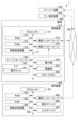
- FIG. 1 is a block diagram showing an example of a main configuration of a digital key system according to an embodiment and components included in the digital key system.
- FIG. 1 is a block diagram showing an example of a main configuration of a digital key system according to an embodiment and components included in the digital key system.
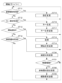
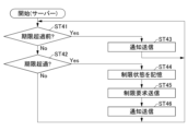
- 4 is a flowchart showing an example of processing by a processor of the server device in FIG. 1 .
- 4 is a flowchart showing an example of processing by a processor of the server device in FIG. 1 .
- 4 is a flowchart showing an example of processing by a processor of the server device in FIG. 1 .
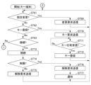
- 4 is a flowchart showing an example of processing by a processor of the key terminal device in FIG. 1 .
- FIG. 4 is a flowchart showing an example of processing by a processor of the key terminal device in FIG. 1 .
- 3 is a flowchart showing an example of processing by a processor of the control device in FIG. 2 .
- 3 is a flowchart showing an example of processing by a processor of the control device in FIG. 2 .
- 3 is a flowchart showing an example of processing by a processor of the terminal device in FIG. 2 .
- the digital key system 1 is a system that provides a digital key service.
- the digital key service is a service that enables a digital key to be used as a key for a vehicle.
- the digital key is a service that enables a portable electronic device having a communication function, such as a smartphone, to be used as a key.
- the digital key service is a service that can limit the function of the digital key if a predetermined condition is not satisfied.
- the digital key system 1 includes, as an example, a server device 100, a key terminal device 200, a vehicle 300, and a terminal device 400. Note that the digital key system 1 may include some of these. Note that, although one each of the server device 100, the key terminal device 200, the vehicle 300, and the terminal device 400 is shown in FIG. 1 and FIG. 2, the number of each component is not limited.
- the server device 100, the key terminal device 200, the vehicle 300, and the terminal device 400 are connected to a network NW.
- the network NW is typically a communication network including the Internet.
- the network NW is typically a communication network including a WAN (wide area network).
- the network NW may be a communication network including a private network such as an intranet.
- the network NW may also be a communication network including a dedicated line or a public mobile phone network.
- the server device 100 is a server for providing the digital key service.
- the server device 100 manages various data in the digital key service and controls the digital keys.
- the server device 100 includes a processor 101, a ROM (read-only memory) 102, a RAM (random-access memory) 103, an auxiliary storage device 104, and a communication interface 105.
- a bus 106 and the like connect these components.
- the server device 100 is an example of an information management device.
- the processor 101 is the central part of the computer that performs calculations and control processes necessary for the operation of the server device 100, and performs various calculations and processes.
- the processor 101 is, for example, a CPU (central processing unit), an MPU (micro processing unit), a SoC (system on a chip), a DSP (digital signal processor), a GPU (graphics processing unit), an ASIC (application specific integrated circuit), a PLD (programmable logic device), or an FPGA (field-programmable gate array).
- the processor 101 is a combination of several of these.
- the processor 101 may also be a combination of these with a hardware accelerator.
- the processor 101 controls each part to realize various functions of the server device 100 based on programs such as firmware, system software, and application software stored in the ROM 102 or the auxiliary storage device 104.
- the processor 101 also executes the processes described below based on the programs.
- part or all of the program may be incorporated into the circuitry of the processor 101.
- the ROM 102 and the RAM 103 are main memory devices of the computer with the processor 101 at its core.
- the ROM 102 is a non-volatile memory used exclusively for reading data.
- the ROM 102 stores, for example, firmware among the above programs.
- the ROM 102 also stores data used by the processor 101 when performing various processes.
- the RAM 103 is a memory used for reading and writing data.
- the RAM 103 is used as a work area for storing data that is temporarily used when the processor 101 performs various processes.
- the RAM 103 is typically a volatile memory.
- the auxiliary storage device 104 is an auxiliary storage device of a computer with the processor 101 at its core.
- the auxiliary storage device 104 is, for example, an EEPROM (electrical erasable programmable read-only memory), a HDD (hard disk drive), or flash memory.
- the auxiliary storage device 104 stores, for example, system software and application software from among the above programs.
- the auxiliary storage device 104 also stores data used by the processor 101 in performing various processes, data generated by the processes in the processor 101, various setting values, etc.
- the data stored in the auxiliary storage device 104 includes, for example, a user DB (database).
- the user DB is a database that stores and manages information about users who use the digital key service.
- the user DB stores information about each user (hereinafter referred to as "user information") in association with a user ID (identifier).
- the user ID is identification information that is uniquely assigned to each user.
- the user information includes, for example, various settings related to the digital key service (hereinafter referred to as "key service settings") and server restriction variables. Default values may be set for each setting included in the key service settings. The default values are set in advance, for example, by the designer or administrator of the key system 1 or the seller of the vehicle 300. Some key service settings may be changeable by the user, and some may not be changeable.
- the server restriction variable indicates whether the digital key of the user identified by the associated user ID is in a restricted or unrestricted state. The restricted and unrestricted states will be described later.
- the communication interface 105 is an interface through which the server device 100 communicates via a network NW or the like.
- the communication interface 105 functions as an example of a communication unit that communicates with a first terminal device.
- the communication interface 105 is also an example of a communication device.
- the processor 101 also functions as an example of a communication control unit that controls the communication device to communicate with the first terminal device by controlling the communication interface 105 to communicate with the first terminal device.
- Bus 106 includes a control bus, an address bus, a data bus, etc., and transmits signals exchanged between each part of server device 100.
- the key terminal device 200 is a portable electronic device with a communication function that can be used as a digital key.
- the digital key can at least restrict and/or release at least one function of the vehicle 300.
- the key terminal device 200 is, for example, a general-purpose electronic device such as a smartphone, a tablet terminal, or a smartwatch.
- the key terminal device 200 may be an electronic device dedicated to digital keys.
- the key terminal device 200 includes a processor 201, a ROM 202, a RAM 203, an auxiliary storage device 204, a communication interface 205, a wireless interface 206, a display device 207, and an input device 208.
- a bus 209 and the like connect these components.
- the key terminal device 200 is an example of a first terminal device.
- a user of the key terminal device 200 is an example of a first user who uses the first terminal device.
- the processor 201 is the central part of the computer that performs the calculations and control processes required for the operation of the key terminal device 200, and performs various calculations and processes.
- the processor 201 is, for example, a CPU, MPU, SoC, DSP, GPU, ASIC, PLD, or FPGA. Alternatively, the processor 201 is a combination of two or more of these. The processor 201 may also be a combination of these with a hardware accelerator or the like.
- the processor 201 controls each part to realize various functions of the key terminal device 200 based on programs such as firmware, system software, and application software stored in the ROM 202 or the auxiliary storage device 204.
- the processor 201 also executes the processes described below based on the programs. Note that some or all of the programs may be incorporated into the circuitry of the processor 201.
- the ROM 202 and the RAM 203 are main memory devices of the computer with the processor 201 at its core.
- the ROM 202 is a non-volatile memory used exclusively for reading data.
- the ROM 202 stores, for example, firmware among the above programs.
- the ROM 202 also stores data used by the processor 201 when performing various processes.
- the RAM 203 is a memory used for reading and writing data.
- the RAM 203 is used as a work area for storing data that is temporarily used when the processor 201 performs various processes.
- the RAM 203 is typically a volatile memory.
- the auxiliary storage device 204 is an auxiliary storage device of a computer with the processor 201 at its core.
- the auxiliary storage device 204 is, for example, an EEPROM, HDD, or flash memory.
- the auxiliary storage device 204 stores, for example, system software and application software among the above programs.
- the auxiliary storage device 204 also stores data used by the processor 201 when performing various processes, data generated by the processes in the processor 201, various setting values, and the like.
- the auxiliary storage device 204 is an example of a storage device.
- the application software stored in the auxiliary storage device 204 includes a key app.
- the key app is application software for using a digital key service.
- the key app is application software that enables the key terminal device 200 to function as a digital key.
- the processor 201 downloads the key app, for example, via the communication interface 205.
- the processor 201 also installs the downloaded key app. Alternatively, the key app may be installed in advance in the key terminal device 200.
- the key app uses the key information to unlock the vehicle 300.
- the key app transmits the key information to the vehicle 300 to allow authentication using the key information.
- the key information is unique for each combination of the target vehicle 300 and the user who will use it. By registering multiple pieces of key information, the key app is able to unlock multiple vehicles 300 that correspond to each piece of key information.
- An expiration date may also be set for the key information. In this case, the key information is only valid within the expiration date.
- the key app includes a restriction variable.
- the restriction variable indicates whether the digital key operated by the key app is in a restricted or unrestricted state.
- the restricted and unrestricted states are described below.
- the key terminal device 200 logs in to the digital key service using a user ID, for example.
- the processor 201 may perform the login automatically, or may perform the login based on an operation by the operator of the key terminal device 200.
- the key terminal device 200 stores the user ID used for logging in. This user ID will be referred to as the "login ID" below.
- the communication interface 205 is an interface that allows the key terminal device 200 to communicate via a network NW, etc.
- the wireless interface 206 is an interface that allows the key terminal device 200 to wirelessly communicate with the vehicle 300.
- the wireless interface 206 includes an antenna for wireless communication, etc.
- the display device 207 displays a screen for notifying the operator of the key terminal device 200 of various information.
- the display device 207 is, for example, a liquid crystal display or an organic electroluminescence (EL) display.
- the input device 208 accepts operations by the operator of the key terminal device 200.
- the input device 208 is, for example, a keyboard, a keypad, a touchpad, a mouse, or a controller.
- the input device 208 may also be a device for voice input.
- a touch panel may also be used as the display device 207 and the input device 208. In this case, the display panel provided in the touch panel functions as the display device 207. And the pointing device provided in the touch panel that uses touch input functions as the input device 208.
- the bus 209 includes a control bus, an address bus, a data bus, etc., and transmits signals exchanged between each part of the key terminal device 200.
- the vehicle 300 is, for example, an automobile.
- the vehicle 300 includes, as an example, a control device 310, a key interface 320, a door 330, a power unit 340, an electrical unit 350, and a start button 360.
- the control device 310 performs various controls of the vehicle 300.
- the control device 310 has a function of authenticating key information read from the key terminal device 200.
- the control device 310 authenticates valid key information, it has a function of unlocking the locked state of the vehicle 300 to an unlocked state.
- the vehicle 300 in the locked state is in a state in which the electronic lock 331 described below is locked, and each part of the vehicle 300, including the power unit 340 and the electrical unit 350, cannot be started.
- the locked state is an example of a locked state in which the vehicle 300 cannot be driven.
- the locked state is an example of a state in which at least one function of the vehicle 300 is restricted.
- the vehicle 300 in the unlocked state is in a state in which the electronic lock 331 is unlocked, and each part of the vehicle 300, including the power unit 340 and the electrical unit 350, can be started.
- the control device 310 is, for example, an ECU (electronic control unit).
- the control device 310 includes, for example, a processor 311, a ROM 312, a RAM 313, an auxiliary storage device 314, a communication interface 315, and a control interface 316.
- a bus 317 and the like connect these components.
- the processor 311 is the central part of the computer that performs calculations and control processes necessary for the operation of the vehicle 300, and performs various calculations and processes.
- the processor 311 is, for example, a CPU, MPU, SoC, DSP, GPU, ASIC, PLD, or FPGA. Alternatively, the processor 311 is a combination of two or more of these. The processor 311 may also be a combination of these with a hardware accelerator or the like.
- the processor 311 controls each part to realize various functions of the vehicle 300 based on programs such as firmware, system software, and application software stored in the ROM 312 or the auxiliary storage device 314.
- the processor 311 also executes processes described below based on the programs. Some or all of the programs may be incorporated into the circuitry of the processor 311.
- the ROM 312 and the RAM 313 are main memory devices of the computer with the processor 311 at its core.
- the ROM 312 is a non-volatile memory used exclusively for reading data.
- the ROM 312 stores, for example, firmware among the above programs.
- the ROM 312 also stores data used by the processor 311 when performing various processes.
- the RAM 313 is a memory used for reading and writing data.
- the RAM 313 is used as a work area for storing data that is temporarily used when the processor 311 performs various processes.
- the RAM 313 is typically a volatile memory.
- the auxiliary storage device 314 is an auxiliary storage device of a computer with the processor 311 at its core.
- the auxiliary storage device 314 is, for example, an EEPROM, a HDD, or a flash memory.
- the auxiliary storage device 314 stores, for example, system software and application software from among the above programs.
- the auxiliary storage device 314 also stores data used by the processor 311 when performing various processes, data generated by the processes in the processor 311, various setting values, etc.
- the data stored in the auxiliary storage device 314 includes the vehicle ID and vehicle setting information of the vehicle 300 in which it is installed.
- the vehicle ID is identification information unique to each vehicle 300.
- the vehicle setting information is information related to the digital key service that includes settings related to the operation of the vehicle 300.
- a default value may be set for each setting included in the vehicle setting information. The default value is set in advance, for example, by the designer or administrator of the key system 1 or the seller of the vehicle 300. Some vehicle setting information may be changeable by the user, and some may not be changeable.
- the communication interface 315 is an interface that allows the vehicle 300 to communicate via a network NW, etc.
- the control interface 316 is an interface through which the control device 310 communicates with each part of the vehicle 300.
- the control device 310 controls each part of the vehicle 300 via the control interface 316.
- These parts include, for example, a key interface 320, a door 330, a power unit 340, an electrical unit 350, and a start button 360.
- Bus 317 includes a control bus, an address bus, a data bus, etc., and transmits signals exchanged between each part of the control device 310.
- the key interface 320 is an interface for wireless communication with the key terminal device 200 that functions as a digital key.
- the key interface 320 includes an antenna for wireless communication, etc.
- Door 330 is a door for entering and exiting vehicle 300.
- Door 330 is, for example, a door for entering and exiting the driver's seat, which is the place where vehicle 300 is driven.
- Door 330 is equipped with an electronic lock 331.
- the electronic lock 331 is an electronic lock that can be opened with a digital key.
- the power unit 340 is the parts and equipment that allow the vehicle 300 to run.
- the power unit 340 is, for example, a power unit, a battery, a drive system, etc.
- the power unit is, for example, an engine or a motor.
- the electrical equipment unit 350 is the components and equipment of the electrical system.
- Examples of the electrical equipment unit 350 include a car air conditioner, in-car Wi-Fi, in-car entertainment, car audio, an in-car display, a car navigation system, in-car devices, and instruments.
- the start button 360 is a button that is operated to start up the power unit 340 and part or all of the electrical unit 350.
- the terminal device 400 is a device that can view various information related to the digital key service and change various settings.
- the terminal device 400 is, for example, a PC (personal computer), a tablet terminal, or a smartphone.
- the terminal device 400 may be the key terminal device 200.
- the terminal device 400 includes a processor 401, a ROM 402, a RAM 403, an auxiliary storage device 404, a communication interface 405, a display device 406, and an input device 407.
- a bus 408 and the like connect these components.
- the terminal device 400 is an example of a second terminal device.
- a user of the terminal device 400 is an example of a second user who uses the second terminal device.
- the application software stored in the terminal device 400 includes a viewing application.
- the viewing application is application software that allows the user to view various information related to the digital key service and change various settings.
- the viewing application may be general-purpose application software such as a web browser, or it may be application software dedicated to the digital key system 1.
- the terminal device 400 logs in to the digital key service in the same way as the key terminal device 200.
- the terminal device 400 stores the login ID.
- the processor 401 is the central part of the computer that performs the calculations and control processes required for the operation of the terminal device 400, and performs various calculations and processes.
- the processor 401 is, for example, a CPU, MPU, SoC, DSP, GPU, ASIC, PLD, or FPGA. Alternatively, the processor 401 is a combination of two or more of these. The processor 401 may also be a combination of these with a hardware accelerator.
- the processor 401 controls each part to realize various functions of the terminal device 400 based on programs such as firmware, system software, and application software stored in the ROM 402 or auxiliary storage device 404.
- the processor 401 also executes the processes described below based on the programs. Some or all of the programs may be incorporated into the circuitry of the processor 401.
- the ROM 402 and the RAM 403 are main storage devices of the computer with the processor 401 at its core.
- the ROM 402 is a non-volatile memory used exclusively for reading data.
- the ROM 402 stores, for example, firmware among the above programs.
- the ROM 402 also stores data used by the processor 401 when performing various processes.
- the RAM 403 is a memory used for reading and writing data.
- the RAM 403 is used as a work area for storing data that is temporarily used when the processor 401 performs various processes.
- the RAM 403 is typically a volatile memory.
- the auxiliary storage device 404 is an auxiliary storage device of a computer with the processor 401 at its core.
- the auxiliary storage device 404 is, for example, an EEPROM, a HDD, or a flash memory.
- the auxiliary storage device 404 stores, for example, system software and application software from among the above programs.
- the auxiliary storage device 404 also stores data used by the processor 401 when performing various processes, data generated by the processes in the processor 401, various setting values, etc.
- the communication interface 405 is an interface through which the terminal device 400 communicates via a network NW, etc.
- the display device 406 displays a screen for notifying the operator of the terminal device 400 of various information.
- the display device 406 is, for example, a display such as a liquid crystal display or an organic EL display.
- the input device 407 accepts operations by the operator of the terminal device 400.
- the input device 407 is, for example, a keyboard, a keypad, a touchpad, a mouse, or a controller.
- the input device 407 may also be a device for voice input.
- a touch panel may also be used as the display device 406 and the input device 407. In this case, the display panel provided in the touch panel functions as the display device 406. And the pointing device provided in the touch panel that is used for touch input functions as the input device 407.
- Bus 408 includes a control bus, an address bus, a data bus, etc., and transmits signals exchanged between each part of terminal device 400.
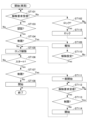
- FIGS 3 to 5 are flowcharts showing an example of the process by the processor 101 of the server device 100.
- the processor 101 executes the processes of Figures 3 to 5 based on a program stored in, for example, the ROM 102 or the auxiliary storage device 104.
- the processor 101 executes the processes of Figures 3 to 5 in parallel or in parallel, for example.
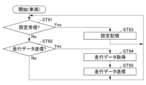
- Figures 6 and 7 are flowcharts showing an example of the process by the processor 201 of the key terminal device 200.
- the processor 201 executes the processes of Figures 6 and 7 based on a program stored in, for example, the ROM 202 or the auxiliary storage device 204.
- Figures 8 and 9 are flowcharts showing an example of the process by the processor 311 of the control device 310.
- the processor 311 executes the processes of Figures 8 and 9 based on a program stored in, for example, the ROM 312 or the auxiliary storage device 314.
- the processor 311 executes, for example, the processes of FIG. 8 and FIG. 9 in parallel or in parallel.
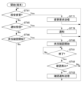
- FIG. 10 is a flowchart showing an example of the process by the processor 401 of the terminal device 400.
- the processor 401 executes the process of FIG. 10 based on a program stored in, for example, the ROM 402 or the auxiliary storage device 404.
- step ST61 of FIG. 6 the processor 201 of the key terminal device 200 determines whether or not to change the key service settings. If the processor 201 determines not to change the key service settings, it determines No in step ST61 and proceeds to step ST62.
- step ST62 processor 201 determines whether or not to newly register key information. If processor 201 determines not to newly register key information, it determines No in step ST62 and proceeds to step ST63.
- step ST63 the processor 201 determines whether or not to connect to the key interface 320. If the processor 201 does not determine to connect to the key interface 320, the processor 201 determines No in step ST63 and proceeds to step ST64.
- step ST64 the processor 201 determines whether or not a restriction request has been received by the communication interface 205. If a restriction request has not been received, the processor 201 determines No in step ST64 and proceeds to step ST65.
- step ST65 the processor 201 determines whether or not notification information has been received by the communication interface 205. If notification information has not been received, the processor 201 determines No in step ST65 and proceeds to step ST66.
- step ST66 processor 201 determines whether or not to start checking the driving situation. If processor 201 does not determine to start checking the driving situation, it determines No in step ST64 and proceeds to step ST67.
- step ST67 the processor 201 determines whether or not a restriction removal request has been received by the communication interface 205. If a restriction removal request has not been received, the processor 201 determines No in step ST67 and proceeds to step ST68.
- step ST68 the processor 201 determines whether or not to lock the vehicle 300.
- the processor 201 determines that the vehicle 300 is to be locked when, for example, an operation instructing that the vehicle 300 is to be locked is performed using the input device 208. If the processor 201 does not determine that the vehicle 300 is to be locked, it determines No in step ST68 and returns to step ST61. Thus, the processor 201 enters a standby state in which it repeats steps ST61 in FIG. 6 to ST68 in FIG.
- the operator When an operator of the key terminal device 200 wishes to change the key service settings, the operator operates the input device 208, for example, to input the changes to the key service settings.
- the processor 201 determines that the key service settings should be changed in response to the input.
- step ST61 in FIG. 6 determines Yes in step ST61 in FIG. 6 and proceeds to step ST68.
- step ST69 the processor 201 generates a change request.
- the change request includes, for example, a login ID and change information.
- the change information indicates the changes to be made to the key service settings.
- the processor 201 instructs the communication interface 205 to send the change request to the server device 100.
- the communication interface 205 sends the change request to the server device 100.
- the sent change request is received by the communication interface 105 of the server device 100.
- the processor 201 returns to step ST61.
- step ST11 of FIG. 3 the processor 101 of the server device 100 determines whether or not a change request has been received by the communication interface 105. If a change request has not been received, the processor 101 determines No in step ST11 and proceeds to step ST12.
- step ST12 the processor 101 determines whether or not a key request has been received by the communication interface 105. If a key request has not been received, the processor 101 determines No in step ST12 and proceeds to step ST13.
- step ST13 the processor 101 determines whether or not a start request has been received by the communication interface 105. If a start request has not been received, the processor 101 determines No in step ST13 and proceeds to step ST14.
- step ST14 the processor 101 determines whether or not a confirmation notification has been received by the communication interface 105. If the processor 101 has not received a confirmation notification, the processor 101 determines No in step ST14 and returns to step ST11. Thus, the processor 101 goes into a standby state in which it repeats steps ST11 to ST14 until a change request, a key request, a start request, or a confirmation notification is received. The key request, start request, and confirmation notification will be described later.
- step ST11 If the processor 101 receives a change request while in a standby state in which it repeats steps ST11 to ST14, it determines Yes in step ST11 and proceeds to step ST15.
- step ST15 the processor 101 changes the key service settings by updating the user DB based on the change request received in step ST11. That is, the processor 101 changes the key service settings associated with the user ID included in the change request in accordance with the change information included in the change request.
- the processor 101 determines whether the changes to the key service settings include changes that require changes to the operation of the vehicle 300. If the changes to the key service settings include changes that require changes to the operation of the vehicle 300, the processor 101 generates setting information.
- the setting information indicates the setting that changes the operation of the vehicle 300.
- the processor 101 instructs the communication interface 105 to transmit the setting information to the control device 310.
- the communication interface 105 Upon receiving this transmission instruction, the communication interface 105 transmits the setting information to the control device 310.
- the transmitted setting information is received by the communication interface 315 of the control device 310. After processing step ST15, the processor 101 returns to step ST11.
- step ST91 of FIG. 8 the processor 311 of the control device 310 determines whether or not the setting information has been received by the communication interface 315. If the setting information has not been received, the processor 311 determines No in step ST91 and proceeds to step ST92.
- step ST92 processor 311 determines whether or not to transmit driving data. If processor 311 does not determine to transmit driving data, it determines No in step ST92 and returns to step ST91. Thus, processor 311 enters a standby state in which it repeats steps ST91 and ST92 until it receives setting information or determines to transmit driving data. Driving data will be described later.
- step ST91 If the processor 311 receives setting information while in a standby state in which steps ST91 and ST92 are repeated, it determines Yes in step ST91 and proceeds to step ST93.
- step ST93 the processor 311 updates the vehicle setting information according to the setting information received in step ST91. After processing step ST93, the processor 311 returns to step ST91.
- the operator When an operator of the key terminal device 200 wishes to register new key information in the key app, the operator inputs an instruction to the key terminal device 200 to register new key information using a predetermined method.
- the processor 201 determines to register a new digital key in response to the input instructing the user to register new key information.
- step ST61 in FIG. 6 to step ST68 in FIG. 7 are repeated, the processor 201 determines Yes in step ST62 and proceeds to step ST70 in FIG. 6.
- the processor 201 In step ST70, the processor 201 generates a key request.
- the key request includes target information.
- the key request is information requesting the transmission of key information identified by the target information.
- the target information is information that can identify the vehicle 300 that the key information targets and the user who will use the key information.
- the processor 201 instructs the communication interface 315 to transmit the key request to the server device 100.
- the communication interface 315 Upon receiving this transmission instruction, the communication interface 315 transmits the key request to the server device 100.
- the transmitted key request is received by the communication interface 105 of the server device 100.
- step ST12 determines Yes in step ST12 and proceeds to step ST16.
- step ST16 the processor 101 generates key information according to the target information included in the key request received in step ST12.
- step ST17 the processor 101 generates a key response.
- the key response includes the key information generated in step ST16.
- the key response is, for example, information instructing to register the key information.
- the processor 101 instructs the communication interface 105 to transmit the key response to the key terminal device 200 that sent the key request.
- the communication interface 105 Upon receiving this transmission instruction, transmits the key response to the key terminal device 200.
- the transmitted key response is received by the communication interface 315 of the key terminal device 200.
- the processor 101 returns to step ST11.
- step ST71 of FIG. 6 the processor 201 of the key terminal device 200 waits for a key response to be received by the communication interface 315. If a key response is received, the processor 201 determines Yes in step ST71 and proceeds to step ST72.
- step ST72 the processor 201 registers the key information included in the key response received in step ST71 in the key app. At this time, the processor 201 stores the key information in the auxiliary storage device 204. After processing in step ST72, the processor 201 returns to step ST61.
- the processor 201 determines to connect to the key interface 320, for example, when the distance between the key terminal device 200 and the key interface 320 is within a predetermined distance.
- the processor 201 determines to connect to the key interface 320, for example, when it receives radio waves transmitted by the key interface 320.
- the processor 201 determines to connect to the key interface 320, for example, when it becomes possible to communicate with the key interface 320.
- the processor 201 determines to connect to the key interface 320 in response to, for example, the holder of the key terminal device 200 waving at the door 330.
- step ST61 in FIG. 6 If the processor 201 determines to connect to the key interface 320 while in a standby state in which it repeats step ST61 in FIG. 6 to step ST68 in FIG. 7, it determines Yes in step ST63 and proceeds to step ST73 in FIG. 6.
- step ST73 the processor 201 establishes communication between the wireless interface 206 and the key interface 320.
- step ST74 the processor 201 determines whether or not the digital key is in a restricted state. If the digital key is not in a restricted state, i.e., if the digital key is in an unrestricted state, the processor 201 determines No in step ST74 and proceeds to step ST75.
- the restricted and unrestricted states will be described later.
- step ST75 the processor 201 generates an unlock request.
- the unlock request is information requesting that the vehicle 300 be unlocked.
- the unlock request includes, for example, a login ID, a restriction variable stored in the auxiliary storage device 204, and key information registered in the key app.
- the value of the restriction variable is a value indicating an unrestricted state.
- the processor 201 instructs the wireless interface 206 to transmit the unlock request to the vehicle 300.
- the wireless interface 206 Upon receiving this transmission instruction, the wireless interface 206 transmits the unlock request to the vehicle 300.
- the transmitted unlock request is received by the key interface 320 of the vehicle 300.
- the processor 201 returns to step ST61.
- the processor 201 of the key terminal device 200 functions as an example of a digital key section that causes the first terminal device to function as a digital key by executing the processes of step ST63 and steps ST73 to ST75 in FIG. 6.
- the processor 311 of the control device 310 starts the process shown in FIG. 9 when, for example, the vehicle 300 is locked. 9, the processor 311 of the control device 310 determines whether or not an unlock request has been received by the key interface 320. If an unlock request has not been received, the processor 311 determines No in step ST101 and proceeds to step ST102.
- step ST102 processor 311 determines whether or not to lock vehicle 300. If processor 311 does not determine that vehicle 300 should be locked, it determines No in step ST102 and returns to step ST101. Thus, processor 311 enters a standby state in which it repeats steps ST101 and ST102 until it receives an unlock request or determines that vehicle 300 should be locked.
- step ST101 If the processor 311 receives an unlock request while in a standby state in which it repeats steps ST101 and ST102, it determines Yes in step ST101 and proceeds to step ST103.
- step ST103 processor 311 performs authentication using the key information included in the unlock request received in step ST101. Processor 311 then determines whether or not the authentication is successful. If the authentication is not successful, processor 311 determines No in step ST103 and returns to step ST101. On the other hand, if the authentication is successful, processor 311 determines Yes in step ST103 and proceeds to step ST104.
- step ST104 the processor 311 refers to the restriction variable included in the unlock request received in step ST101 to determine whether the digital key is in a restricted state. If the digital key is not in a restricted state, the processor 311 determines No in step ST104 and proceeds to step ST104.
- step ST105 the processor 311 controls the electronic lock 331 to unlock it. This allows the holder of the key terminal device 200 to enter the vehicle 300. Once inside the vehicle 300, if the holder or the like wishes to start each part of the vehicle 300, such as the power unit 340, the holder or the like performs an operation to start the vehicle 300, for example, by operating the start button 360.
- step ST106 processor 311 waits for an operation to start vehicle 300 to be performed. That is, processor 311 waits for a predetermined operation, such as operating start button 360, to be performed. If an operation to start vehicle 300 has been performed, processor 311 determines Yes in step ST106 and proceeds to step ST107.
- step ST107 processor 311 refers to the restriction variable included in the unlock request received in step ST101 to determine whether the digital key is in a restricted state. If the digital key is not in a restricted state, processor 311 determines No in step ST107 and proceeds to step ST108.
- step ST108 processor 311 starts each part of vehicle 300. After processing step ST108, processor 311 ends the processing shown in FIG. 9.
- the vehicle 300 has a function of recording driving data for each driver.
- the driver of the vehicle 300 is identified by the user ID included in the unlock request received in step ST101 of FIG. 9.
- the control device 310 records the driving data using, for example, various sensors.
- the driving data includes, for example, a driving route, a speed history, an acceleration history, a jerk history, a brake opening history, a braking timing history, a history of sudden braking, an accelerator opening history, an accelerator timing history, a steering angle history, a steering timing history, a history of deviation from the driving lane, a collision mitigation brake operation history, a history of failure to stop at a stop sign, a history of failure to signal at an intersection, etc., a history of slow-down violations at an intersection, etc., a history of wrong-way driving, a history of speeding, an excessive acceleration when speeding, information indicating whether each road on the driving route is an expressway, information indicating whether the driver recognized each road sign that should be checked while driving, a
- the vehicle 300 also has a function of transmitting the driving data to the server device 100.
- the control device 310 transmits the driving data at a predetermined timing, for example.
- the predetermined timing is, for example, a regular timing.
- the predetermined timing is the timing when the driver stops driving the vehicle 300.
- the predetermined timing is the timing when the vehicle 300 is locked.
- the processor 311 of the control device 310 determines to transmit the driving data when the predetermined timing arrives.
- step ST92 If the processor 311 determines that driving data is to be transmitted while in a standby state in which steps ST91 and ST92 in FIG. 8 are repeated, it determines Yes in step ST92 and proceeds to step ST94.
- step ST94 the processor 311 acquires any unsent driving data of the driver identified by the user ID included in the unlock request received in step ST101 of FIG. 9.
- step ST95 of FIG. 8 the processor 311 generates driving data information.
- the driving data information includes the driving data acquired in step ST94 and the user ID included in the unlock request received in step ST101 of FIG. 9.
- the processor 311 instructs the communication interface 315 to transmit the driving data information to the server device 100.
- the communication interface 315 transmits the driving data information to the server device 100.
- the transmitted driving data information is received by the communication interface 105 of the server device 100.
- the processor 311 returns to step ST91.
- step ST31 of FIG. 4 the processor 101 of the server device 100 waits for the reception of driving data information by the communication interface 105. If the driving data information is received, the processor 101 judges Yes in step ST31 and proceeds to step ST32.
- step ST32 the processor 101 analyzes the driving data included in the driving data information received in step ST31.
- the analysis includes a diagnosis of the driving situation.
- the processor 101 may also use driving data previously stored in the user DB for analysis.
- the processor 101 acquires the driving data by controlling the communication interface 105 to receive driving data information.
- the processor 101 acquires the analysis results of the driving data by executing the processing of step ST32.
- the processor 101 functions as an example of an acquisition unit that acquires the operating status of the machine by the first user by at least one of receiving the driving data information and executing the processing of step ST32.
- step ST33 the processor 101 stores the driving data included in the driving data information received in step ST31 and the analysis results of step ST32 in the user DB in association with the user ID included in the driving data information.
- the processor 101 functions as an example of a storage unit that stores the driving status by performing the processing of step ST33 in cooperation with the auxiliary storage device 104.
- the processor 101 functions as an example of a storage unit by controlling the auxiliary storage device 104 to perform the processing of step ST33.
- step ST34 processor 101 determines whether to place restrictions on the digital key used by the user and put it into a restricted state based on the driving data and the analysis results of step ST32.
- the user in question is the user identified by the user ID included in the driving data information received in step ST31.
- Processor 101 determines to put the digital key into a restricted state, for example, if it determines that there is a problem with the user's driving that is sufficient to warrant putting restrictions on the digital key.
- Examples of problems that may be considered to be problematic to the extent that the digital key is restricted include, for example, the number of sudden braking is more than a predetermined number, the number of deviations from the driving lane is more than a predetermined number, the collision mitigation brake is activated more than a predetermined number, the number of failures to stop at a stop sign is more than a predetermined number, the number of failures to signal at an intersection is more than a predetermined number, the number of violations of slowing down at an intersection is more than a predetermined number, the number of times that the vehicle is traveling in the wrong direction is more than a predetermined number, the number of times that the vehicle is overspeeding is more than a predetermined number, the number of times that the vehicle is overspeeding by a speeding rate more than a predetermined number, the frequency of use of the expressway is within a predetermined frequency range, the number of times that the driver does not recognize each road sign that must be checked while driving is more than a predetermined number, the number of times that the driver falls asleep
- the processor 101 may also consider that there is a problem that may be considered to be problematic to the extent that the digital key is restricted when the processor 101 determines that the user's driving is not safe. If the processor 101 does not determine that the digital key is to be restricted, the processor 101 determines No in step ST34 and returns to step ST31. On the other hand, if the processor 101 determines that the digital key should be placed in a restricted state, it judges Yes in step ST34 and proceeds to step ST35.
- the processor 101 functions as an example of a determination unit that determines whether the first user using the first terminal device satisfies a specified condition. Furthermore, a problem that is severe enough to place restrictions on the digital key is an example of a problem with the first user's driving. Therefore, the specified condition in step ST34 is that there is a problem with the first user's driving.
- step ST35 the processor 101 updates the user DB, and sets the value of the server restriction variable associated with the user ID included in the driving data information received in step ST31 to a value indicating a restricted state.
- the processor 101 also updates the user DB, and resets the date and time when each user last checked the driving situation identified by the user ID. The date and time when the driving situation was checked will be described later.
- step ST36 the processor 101 instructs the communication interface 105 to send a restriction request to the key terminal device 200 used by the user ID included in the driving data information received in step ST31.
- the restriction request is information that instructs the digital key to be placed in a restricted state.
- the communication interface 105 Upon receiving this instruction to send, the communication interface 105 sends the restriction request to the key terminal device 200.
- the sent restriction request is received by the communication interface 315 of the key terminal device 200.
- the processor 101 returns to step ST31.
- the processor 101 executes a process to send a restriction request, and functions as an example of a restriction unit that places the digital key in a restricted state in which at least a portion of the machine lock cannot be released if a specified condition is met.
- the processor 101 cooperates with the communication interface 105 to send a restriction request, and functions as an example of a restriction unit.
- the processor 201 of the key terminal device 200 receives a restriction request while in a standby state in which it repeats step ST61 in FIG. 6 to step ST68 in FIG. 7, it determines Yes in step ST64 and proceeds to step ST78 in FIG. 7.
- step ST78 the processor 201 places the digital key in a restricted state. To do so, the processor 201 rewrites the value of the restricted variable to a value that indicates the restricted state.
- the processor 201 in cooperation with the auxiliary storage device 204, performs the processing of step ST78 in response to receiving a restriction request, thereby functioning as an example of a restriction storage unit that stores the fact that the digital key is in a restricted state in accordance with control by the restriction unit. Also, the processor 201 performs the processing of step ST78 in response to receiving a restriction request, thereby functioning as an example of a restriction storage unit that stores in the storage device that the digital key is in a restricted state in accordance with control by the restriction unit.
- step ST79 the processor 201 notifies the holder of the key terminal device 200 that the digital key has entered a restricted state by notifying the holder of the key terminal device 200 that the digital key has entered a restricted state.
- the processor 201 for example, causes the display device 207 to display an image indicating that the digital key has entered a restricted state and that the restricted state will be released if the driving situation is confirmed.
- the processor 201 may also notify by outputting sound from a speaker, illuminating a light-emitting device, vibrating a vibrator, or the like.
- the processor 201 may also notify by a push notification.
- the processor 201 returns to step ST61 in FIG. 6.
- a user of the digital key service can check the driving status of the vehicle 300 being driven by himself or another user.
- the driving status is based on the driving data and analysis results stored in step ST33.
- the digital key system 1 also has a function of restricting the digital key used by a user (hereinafter referred to as the "driving user” for distinction) when the driving status of the user has not been confirmed by a predetermined user (hereinafter referred to as the "predetermined user” for distinction) within a predetermined period P1.
- the predetermined period P1 is, for example, a period from the present to a predetermined time ago.
- the predetermined time is determined by hours, days, weeks, months, or years.
- the driving user and the predetermined user may be the same or different. Which user is the predetermined user is determined by the key service settings of the driving user. It is assumed that the predetermined user is set to, for example, a family member or user of the driving user. There may be multiple predetermined users.
- the driving user may or may not be included.
- the digital key system 1 restricts the digital key, for example, when none of the predetermined users have confirmed the driving status within the predetermined period P1.
- the digital key system 1 restricts the digital key when at least N of the predetermined users have not confirmed the driving status within the predetermined period P1.
- N is an integer equal to or greater than 1 and less than the number of specified users.
- the condition for restricting the digital key when there are multiple specified users is determined, for example, by the key service settings of the driving user.
- the condition for restricting the digital key when there is one specified user is that the driving status has not been confirmed by the specified user within a specified period P1.
- the condition for restricting the digital key is met when the driving status of the driving user is not confirmed by the specified user within the specified period P1, which is referred to as "the confirmation of the driving status exceeding the deadline."
- the length of the specified period P1 is determined, for example, by the key service settings of the driving user.
- the specified period P1 is an example of a first specified period.
- step ST41 of FIG. 5 the processor 101 of the server device 100 determines whether there is a driving user whose period until the deadline for checking the driving status is exceeded is equal to or less than the predetermined period P2.
- the processor 101 makes this determination, for example, by referring to the user DB.
- the user DB stores, for each driving user, the date and time when the specified user last checked the driving status. If there is no driving user whose period until the deadline for checking the driving status is exceeded is equal to or less than the predetermined period P2, the processor 101 determines No in step ST41 and proceeds to step ST42.
- step ST42 the processor 101 determines whether there is a driving user whose confirmation of the driving status has expired.
- the processor 101 makes this determination by, for example, referring to a user DB. If there is no driving user whose confirmation of the driving status has expired, the processor 101 determines No in step ST42 and returns to step ST41. Thus, the processor 101 enters a standby state in which it repeats steps ST41 and ST42 until the period until the confirmation of the driving status expires becomes equal to or shorter than the predetermined period P2 or until the confirmation of the driving status expires.
- step ST41 When the processor 101 is in a standby state in which steps ST41 and ST42 are repeated, if the processor 101 determines that there is a driving user whose driving status confirmation deadline is within the predetermined period P2, the processor 101 determines Yes in step ST41 and proceeds to step ST43.
- step ST43 the processor 101 instructs the communication interface 105 to transmit the first notification information to the key terminal device 200 used by the driving user for whom the period until the deadline for checking the driving status has fallen below the predetermined period P2, and to the terminal device 400 used by a predetermined user other than the driving user among the predetermined users of the driving user.
- the first notification information is information indicating that the deadline for checking the driving status is about to expire.
- the first notification information is a type of notification information.
- the communication interface 105 transmits the first notification information to the key terminal device 200 and the terminal device 400.
- the transmitted first notification information is received by the communication interface 315 of the key terminal device 200.
- the transmitted first notification information is received by the communication interface 405 of the terminal device 400.
- the processor 101 returns to step ST41.
- the period during which the driving status has not been checked until the predetermined period P1 has elapsed is equal to or less than the predetermined period P2, which is an example of a second predetermined period.
- (second predetermined period) (predetermined period P1) - (predetermined period P2).
- the processor 201 of the key terminal device 200 receives notification information while in a standby state in which it repeats step ST61 in FIG. 6 to step ST68 in FIG. 7, it determines Yes in step ST65 and proceeds to step ST80 in FIG. 7.
- processor 201 notifies the user of the content indicated by the notification information in order to notify the user of the content.
- Processor 201 for example, causes display device 207 to display an image indicating that the deadline for checking the driving status is about to expire.
- Processor 201 may also notify the user by outputting sound from a speaker, illuminating a light-emitting device, vibrating a vibrator, or the like.
- Processor 201 may also notify the user by a push notification.
- processor 201 returns to step ST61 in FIG. 6.
- the processor 401 of the terminal device 400 performs the same processing as part of the processing performed by the processor 201 of the key terminal device 200 in FIG. 6 and FIG. 7.
- the part in question is steps ST61, ST65, ST66, ST69, and ST80 to ST84.
- the same parts as the processing performed by the processor 201 of the key terminal device 200 in FIG. 6 and FIG. 7 will not be described.
- the processing performed by the processor 401 in FIG. 10 is the same as that in FIG. 6 and FIG.
- keyboard terminal device 200 is replaced with “terminal device 400”, "processor 201” with “processor 401”, “communication interface 205" with “communication interface 405", "display device 207” with “display device 406”, and “input device 208” with “input device 407”.
- step ST61 of the terminal device 400 determines No in step ST61 of FIG. 10 If the processor 401 of the terminal device 400 determines No in step ST61 of FIG. 10, it proceeds to step ST65. If the processor 401 determines No in step ST66, it returns to step ST61. Thus, the processor 401 enters a standby state in which it repeats steps ST61, ST65, and ST66 of FIG. 10 until it determines that the key service setting should be changed, notification information has been received, or confirmation of the driving situation has begun.
- step ST42 determines Yes in step ST42 and proceeds to step ST44.
- step ST44 the processor 101 updates the user DB and sets the value of the server restriction variable associated with the user ID of the driving user whose driving status confirmation deadline has expired to a value indicating the restricted state.
- step ST45 the processor 101 instructs the communication interface 105 to send a restriction request to the key terminal device 200 used by the driving user whose driving status confirmation deadline has expired.
- the communication interface 105 Upon receiving this instruction to send, the communication interface 105 sends the restriction request to the key terminal device 200.
- the sent restriction request is received by the communication interface 315 of the key terminal device 200.
- the processor 101 functions as an example of a determination unit that determines whether a predetermined condition is met by a first user using a first terminal device that functions as a digital key used to release a lock that prevents the machine from being operated.
- the predetermined condition in step ST42 when the driving user is a predetermined user is that the first user has not checked the driving status for a first predetermined period or more.
- the predetermined condition in step ST42 when the predetermined user is someone other than the driving user is that a second user has not checked the driving status for a first predetermined period or more.
- step ST46 the processor 101 instructs the communication interface 105 to transmit the second notification information to a terminal device 400 used by a specified user other than the driving user whose driving status confirmation deadline has expired.
- the second notification information is information indicating that the deadline for confirming the driving status has expired.
- the second notification information is a type of notification information.
- the communication interface 105 Upon receiving this instruction to transmit, the communication interface 105 transmits the second notification information to the terminal device 400.
- the transmitted second notification information is received by the communication interface 405 of the terminal device 400.
- the processor 101 returns to step ST41.
- step ST37 the processor 101 instructs the communication interface 105 to transmit the second notification information to a terminal device 400 used by a predetermined user other than the driving user, among the predetermined users of the driving users whose driving status confirmation deadline has expired.
- the communication interface 105 Upon receiving this transmission instruction, transmits the second notification information to the terminal device 400.
- the transmitted second notification information is received by the communication interface 405 of the terminal device 400.
- the operator of the key terminal device 200 wishes to check the driving situation, for example, the operator uses the input device 208 to perform an operation input indicating that checking of the driving situation should be started.
- the processor 201 of the key terminal device 200 determines to start checking the driving situation in response to the operation input.
- step ST61 in FIG. 6 to step ST68 in FIG. 7 are repeated, it determines Yes in step ST64 and proceeds to step ST81 in FIG. 7.
- the processor 201 In step ST81, the processor 201 generates a start request.
- the start request includes, for example, a login ID and a target ID.
- the target ID indicates which user's driving status is to be started.
- the target ID is the user ID of the user. In this case, the target ID is the same as the login ID.
- the start request is information indicating that the driving status is to be started.
- the start request is also information requesting the transmission of information necessary to check the driving status of the user identified by the target ID.
- the processor 201 instructs the communication interface 205 to transmit the start request to the server device 100.
- the communication interface 205 Upon receiving this transmission instruction, the communication interface 205 transmits the start request to the server device 100.
- the transmitted start request is received by the communication interface 105 of the server device 100.
- the operator of the terminal device 400 wishes to check the driving status
- the operator uses the input device 407 to perform an operation input indicating that he or she wishes to start checking the driving status.
- the operator of the terminal device 400 also uses the input device 407 to perform an operation input specifying which user's driving status to check.
- a user who can be designated is a driving user for whom the user specified by the login ID is the specified user.
- a user who can be designated is a user who has given permission to check the driving status to the user specified by the login ID. Which users a user has given permission to check the driving status is determined by the key service settings of the user who has given permission to check the driving status.
- the target ID in the start request generated by the processor 401 in step ST81 of FIG. 10 is the user ID of the user designated as the target for checking the driving status.
- step ST13 determines Yes in step ST13 and proceeds to step ST18.
- step ST18 the processor 101 refers to the user DB to obtain the analysis results and driving data associated with the target ID included in the start request received in step ST13.
- step ST19 the processor 101 generates a start response.
- the start response includes the analysis results and driving data acquired in step ST18, and the target ID included in the start request received in step ST13.
- the start response is information that instructs the analysis results and driving data to be displayed.
- the processor 101 instructs the communication interface 105 to transmit the start response to the key terminal device 200 or the terminal device 400 that sent the start request.
- the communication interface 105 transmits the start response to the key terminal device 200 or the terminal device 400.
- the transmitted start response is received by the communication interface 205 of the key terminal device 200 or the communication interface 405 of the terminal device 400.
- the processor 101 returns to step ST11.
- the processor 101 performs a process of transmitting a start response to the key terminal device 200, thereby communicating with the first terminal device, and functions as an example of a display control unit that displays the driving status on the first terminal device.
- the processor 101 functions as an example of a display control unit in cooperation with the communication interface 105.
- the processor 101 performs a process of transmitting a start response to the terminal device 400, thereby functions as an example of a display control unit that displays the driving status on the second terminal device.
- step ST82 of FIG. 7 the processor 201 of the key terminal device 200 waits for a start response to be received by the communication interface 205. If a start response is received, the processor 201 judges Yes in step ST82 and proceeds to step ST83.
- step ST83 the processor 201 starts a process for checking the driving situation.
- the processor 201 causes, for example, the display device 207 to display a confirmation screen.
- the confirmation screen includes, for example, the driving data and analysis results included in the start response received in step ST82.
- the confirmation screen may span multiple pages.
- the confirmation screen may be scrollable.
- the operator of the key terminal device 200 checks the driving situation. That is, the operator looks at the driving data and analysis results displayed on the display device 207.
- the operator wants to finish checking the driving situation he or she uses the input device 407 to input an operation indicating that he or she is instructing the operator to finish checking the driving situation.
- step ST84 processor 201 waits for an operation to be performed that instructs the process for checking the driving status to end. That is, processor 201 waits for a predetermined operation, such as operating a button that instructs the process for checking the driving status to end. If an operation to instruct the process for checking the driving status to end is performed, processor 201 determines Yes in step ST84 and proceeds to step ST85.
- step ST85 the processor 201 determines whether the operator of the key terminal device 200 has checked the driving situation.
- the processor 201 determines that the operator has checked the driving situation, for example, when the time taken by the operator to check the driving situation is equal to or longer than a predetermined time.
- the time taken by the operator to check the driving situation is, for example, the time from the execution of the process of step ST83 to the determination of Yes in step ST84.
- the processor 201 determines that the operator has checked the driving situation, for example, when a predetermined number of pages or more or all pages of the confirmation screen are displayed.
- the processor 201 determines that the operator has checked the driving situation, for example, when the confirmation screen is scrolled to a predetermined number of pages or more or when the confirmation screen is completely scrolled.
- the confirmation screen may also display a test regarding the driving situation.
- the processor 201 determines that the operator has checked the driving situation, for example, when the answer to the test by the operator is equal to or higher than a predetermined score.
- the confirmation screen may also include a video.
- processor 201 determines that the operator has checked the driving situation when the video has been played for a predetermined time or in its entirety.
- Processor 201 may also determine that the operator has checked the driving situation when a combination of the above conditions is met. If processor 201 does not determine that the operator has checked the driving situation, it determines No in step ST85 and returns to step ST61 in FIG. 6. On the other hand, if processor 201 determines that the operator has checked the driving situation, it determines Yes in step ST85 and proceeds to step ST86.
- the processor 201 may also assume that the operator of the key terminal device 200 has confirmed the driving situation without any particular conditions. In this case, for example, if the processor 201 judges Yes in step ST8, it proceeds to step ST86.
- step ST86 the processor 201 generates a confirmation notification.
- the confirmation notification includes the login ID and the target ID included in the start response received in step ST82.
- the confirmation notification is information indicating that the user identified by the login ID has confirmed the driving status of the user identified by the target ID.
- the processor 201 instructs the communication interface 205 to transmit the confirmation notification to the server device 100.
- the communication interface 205 transmits the confirmation notification to the server device 100.
- the transmitted confirmation notification is received by the communication interface 105 of the server device 100.
- the processor 201 returns to step ST61 in FIG. 6.
- step ST14 determines Yes in step ST14 and proceeds to step ST20.
- step ST20 of FIG. 3 the processor 101 of the server device 100 stores in the user DB the date and time when the user identified by the login ID last checked the driving status.
- the processor 101 stores, for example, the current date and time in association with the login ID and target ID included in the confirmation notification received in step ST14.
- the current date and time indicates the date and time when the user identified by the login ID checked the driving status of the user identified by the target ID.
- step ST21 the processor 101 determines whether or not to lift the restriction on the digital key of the user identified by the target ID included in the confirmation notification received in step ST14. If the user identified by the login ID included in the confirmation notification received in step ST14 is not the specified user of the driving user identified by the target ID, the processor 101 does not determine to lift the restriction on the digital key. On the other hand, if the user identified by the login ID is the specified user of the driving user identified by the target ID, the processor 101 refers to the user DB and checks the value of the server restriction variable associated with the target ID included in the confirmation notification received in step ST14. If the value indicates a non-restricted state, the processor 101 does not determine to lift the restriction on the digital key.
- the processor 101 checks whether the confirmation of the driving status of the user identified by the target ID has expired. If the confirmation of the driving status has expired, the processor 101 does not determine to lift the restriction on the digital key. On the other hand, if the deadline for confirming the driving status has not passed, the processor 101 determines that the restriction on the digital key is to be lifted. If the processor 101 does not determine that the restriction on the digital key is to be lifted, the processor 101 determines No in step ST21 and returns to step ST11. On the other hand, if the processor 101 determines that the restriction on the digital key is to be lifted, the processor 101 determines Yes in step ST21 and proceeds to step ST22.
- step ST22 the processor 101 updates the user DB and sets the value of the server restriction variable associated with the target ID included in the confirmation notification received in step ST14 to a value indicating the restricted state.
- step ST23 the processor 101 instructs the communication interface 105 to send a restriction release request to the key terminal device 200 used by the user identified by the target ID included in the confirmation notification received in step ST14.
- the restriction release request is information that instructs the restriction state of the digital key to be released and put into an unrestricted state.
- the communication interface 105 Upon receiving this instruction to send, the communication interface 105 sends the restriction release request to the key terminal device 200.
- the sent restriction release request is received by the communication interface 205 of the key terminal device 200.
- the processor 101 returns to step ST11.
- the processor 201 of the key terminal device 200 receives a restriction release request while in a standby state in which it repeats step ST61 in FIG. 6 to step ST68 in FIG. 7, it determines Yes in step ST67 and proceeds to step ST87 in FIG. 7.
- step ST87 the processor 201 releases the restricted state of the digital key and sets it to an unrestricted state. To do this, the processor 201 rewrites the value of the restricted variable to a value that indicates an unrestricted state.
- step ST88 the processor 201 notifies the holder of the key terminal device 200 that the restricted state of the digital key has been released and is now in an unrestricted state by issuing a notification that the restricted state of the digital key has been released and is now in an unrestricted state.
- the processor 201 for example, causes the display device 207 to display an image indicating that the restricted state of the digital key has been released and is now in an unrestricted state.
- the processor 201 may also issue the notification by outputting sound from a speaker, by causing a light-emitting device to emit light, by causing a vibrator to vibrate, or by other means.
- the processor 201 may also issue the notification by a push notification.
- the processor 201 returns to step ST61 in FIG. 6.
- the following describes the operation of the key terminal device 200 and the vehicle 300 when the digital key is in a restricted state.
- step ST74 If the digital key is in a restricted state, the processor 201 of the key terminal device 200 judges Yes in step ST74 and proceeds to step ST76.
- step ST76 the processor 201 generates an unlock request.
- the value of the restriction variable included in the unlock request indicates the restricted state.
- the processor 201 instructs the wireless interface 206 to transmit the unlock request to the vehicle 300.
- the wireless interface 206 Upon receiving this transmission instruction, the wireless interface 206 transmits the unlock request to the vehicle 300.
- the transmitted unlock request is received by the key interface 320 of the vehicle 300.
- step ST77 the processor 201 notifies the holder of the key terminal device 200 that the digital key is in a restricted state, by notifying the holder of the key terminal device 200 that the digital key is in a restricted state.
- the processor 201 for example, causes the display device 207 to display an image indicating that the digital key is in a restricted state and that the restricted state will be released if the driving situation is confirmed.
- the processor 201 may also notify by outputting sound from a speaker, by illuminating a light-emitting device, by vibrating a vibrator, or the like.
- the processor 201 may also notify by a push notification.
- the processor 201 After processing of step ST77, the processor 201 returns to step ST61.
- step ST104 in FIG. 9 judges step ST104 in FIG. 9 as Yes and proceeds to step ST109.
- step ST109 the processor 311 notifies the user of the digital key that the digital key is in a restricted state.
- the processor 311 notifies the user by voice, for example.
- processor 311 refers to the vehicle setting information and determines whether or not electronic lock 331 is set to unlock when the digital key is in a restricted state. If processor 311 determines that electronic lock 331 is not set to unlock when the digital key is in a restricted state, processor 311 determines No in step ST110 and returns to step ST101. On the other hand, if processor 311 determines that electronic lock 331 is set to unlock when the digital key is in a restricted state, processor 311 determines Yes in step ST110 and proceeds to step ST104.
- the vehicle 300 goes from a locked state to a partially locked state.
- the partially locked state is a state in which a part of the vehicle 300 is unlocked.
- the part includes at least the electronic lock 331.
- the partially locked state is therefore a state in which some or all of the parts of the vehicle 300 cannot be started. It is preferable that the vehicle 300 in the partially locked state cannot be driven.
- the partially locked state is an example of a state in which at least one function of the vehicle 300 is restricted.
- step ST107 the processor 311 determines Yes in step ST107 and proceeds to step ST111.
- processor 311 refers to the vehicle setting information to identify parts and equipment that are set to start even when the digital key is in a restricted state. Processor 311 then starts the operation of the identified parts and equipment. However, it is preferable that processor 311 does not allow vehicle 300 to be driven. Note that if there are no parts or equipment other than electronic lock 331 that are set to start even when the digital key is in a restricted state, processor 311 does not start the operation of any parts or equipment in the processing of step ST111. Even after processing of step ST111, vehicle 300 remains in a partially locked state.
- step ST112 the processor 311 waits for an unlock request to be received by the key interface 320. If an unlock request is received, the processor 311 determines Yes in step ST112 and proceeds to step ST113.
- step ST113 processor 311 refers to the restriction variable included in the unlock request received in step ST112 to determine whether or not the digital key is in a restricted state. If the digital key is in a restricted state, processor 311 determines Yes in step ST113 and returns to step ST112. On the other hand, if the digital key is in an unrestricted state, processor 311 determines No in step ST113 and proceeds to step ST114.
- step ST114 processor 311 starts each part of vehicle 300.
- processor 311 ends the processing shown in FIG. 9. In this way, when the digital key changes from a restricted state to an unrestricted state, vehicle 300 changes from a partially locked state to an unlocked state.
- the operator of the key terminal device 200 wishes to lock the vehicle 300
- the operator uses the input device 208 to perform an operation to instruct the key terminal device 200 to lock the vehicle 300. Note that this operation may be possible only when the vehicle 300 is in a partially locked or unlocked state.
- the operator wishes to lock the vehicle 300, he or she leaves the vehicle 300 while holding the key terminal device 200.
- step ST89 If the processor 201 of the key terminal device 200 determines that the vehicle 300 should be locked while in a standby state in which steps ST61 in FIG. 6 to ST68 in FIG. 7 are repeated, it determines Yes in step ST in FIG. 7 and proceeds to step ST89.
- step ST89 the processor 201 generates a lock request.
- the lock request is information requesting that the vehicle 300 be locked.
- the lock request includes, for example, a login ID, a restriction variable stored in the auxiliary storage device 204, and key information registered in the key app.
- the processor 201 instructs the wireless interface 206 to transmit the lock request to the vehicle 300.
- the wireless interface 206 transmits the lock request to the vehicle 300.
- the transmitted lock request is received by the key interface 320 of the vehicle 300.
- the processor 201 returns to step ST61.
- the processor 311 of the control device 310 determines to lock the vehicle 300 when a lock request is received by the key interface 320.
- the processor 311 also determines to lock the vehicle 300 when the key terminal device 200 moves away from the vehicle 300 by a predetermined distance or more.
- step ST102 determines Yes in step ST102 and proceeds to step ST115.
- step ST115 processor 311 puts vehicle 300 into a locked state. That is, processor 311 stops each part of vehicle 300 that was started in steps ST108, ST111, and ST114. Furthermore, processor 311 controls electronic lock 331 to lock electronic lock 331. After processing step ST115, processor 311 returns to step ST101.
- the digital key system 1 of the embodiment puts the digital key into a restricted state when a driver using the digital key meets a specified condition. This allows the digital key system 1 of the embodiment to encourage the driver not to meet the specified condition. If the specified condition is related to safe driving, the digital key system 1 of the embodiment can encourage the driver to drive safely.
- the digital key system 1 of the embodiment also displays the driving status of the driver on the key terminal device 200, which functions as a digital key.
- the digital key system 1 of the embodiment also places the digital key in a restricted state if the driver has not checked the driving status for a predetermined period of time P1 or more. This allows the digital key system 1 of the embodiment to prompt the driver to check the driving status. Checking the driving status provides an opportunity for the driver to reflect on his or her driving. Therefore, the digital key system 1 of the embodiment can encourage the driver to drive safely.
- the digital key system 1 of the embodiment notifies the key terminal device 200 or the terminal device 400 that the deadline for checking the driving status is about to expire. This allows the digital key system 1 of the embodiment to inform the user that the deadline for checking the driving status is about to expire and that restrictions are about to be imposed on the digital key.
- the digital key system 1 of the embodiment also puts the digital key into a restricted state if there is a problem with the driving of the driving user. In response to this, the driving user is expected to drive in such a way that the digital key is not put into a restricted state. Therefore, the digital key system 1 of the embodiment can encourage the driving user to drive safely.
- the digital key system 1 of the embodiment can also display the driving status on the terminal device 400 used by a user other than the driver. This allows, for example, if the different user is a family member of the driver, the family member to know the driving status of the driver. Also, for example, if the different user is a rental car company that is planning to provide a rental car to the driver, the rental car company can know the driving status of the driver before providing the rental car. The rental car company can also cancel the provision of the rental car if the driving status is poor.
- the digital key system 1 of the embodiment also displays the driving status of the driving user on the terminal device 400 used by a specified user different from the driving user.
- the digital key system 1 of the embodiment also places the digital key in a restricted state if the specified user has not checked the driving status for a specified period of time P1 or more. This allows the digital key system 1 of the embodiment to allow the family of the driving user to check the driving status.
- the digital key system 1 of the embodiment also stores the driving status of the driving user. This allows the digital key system 1 of the embodiment to accumulate the driving status of the driving user. Therefore, the digital key system 1 of the embodiment can also analyze the driving status more accurately.
- the digital key is used to unlock the electronic lock 331 of the door 330. Therefore, the digital key system 1 of the embodiment can restrict the digital key, thereby preventing the driving user from driving the vehicle.
- the electronic lock 331 can be unlocked even when the digital key is in a restricted state.
- the driver can enter the vehicle 300 even if the digital key is in a restricted state. Therefore, the driver can retrieve luggage from the vehicle, take a rest in the vehicle, etc., even if the digital key is in a restricted state.
- the digital key system 1 of the embodiment even if the digital key is in a restricted state, when the start button 360 is operated, it is possible to start some of the parts and equipment of the vehicle 300. In this case, even if the digital key is in a restricted state, the driver can use, for example, the car audio, the in-car Wi-Fi, and the car navigation system.
- the above embodiment can be modified as follows. If the digital key is in a restricted state, the key terminal device 200 does not need to send an unlock request. In this case, for example, if the processor 201 determines Yes in step ST74, it proceeds to step ST77. Also, in this case, the processor 311 of the control device 310 does not need to determine whether the digital key is in a restricted state. That is, if the processor 311 determines Yes in step ST103, it proceeds to step ST104. And if the processor 311 determines Yes in step ST106, it proceeds to step ST108.
- step ST63 determines Yes in step ST63
- step ST74 determines Yes in step ST74
- step ST77 determines No in step ST74
- step ST73 the processor 201 proceeds to step ST75.
- the control device 310 may determine whether the digital key is in a restricted state by inquiring of the server device 100. In this case, the key terminal device 200 does not need to determine whether the digital key is in a restricted state.
- the vehicle 300 can be locked regardless of whether the digital key is in a restricted state. However, it is not necessary that the vehicle 300 cannot be locked when the digital key is in a restricted state.
- the processor 201 of the key terminal device 200 does not send a lock request when the digital key is in a restricted state, for example.
- the processor 311 of the control device 310 refers to a restriction variable included in the received lock request to determine whether the digital key is in a restricted state. Then, the processor 311 does not lock the vehicle 300 when the digital key is in a restricted state. Whether or not to lock the vehicle 300 when the digital key is in a restricted state may be changeable by settings.
- the setting is stored in the auxiliary storage device 314 as vehicle setting information.
- the processor 311 refers to the vehicle setting information and locks the parts and equipment that are set to be lockable even in a restricted state. That is, the processor 311 stops the parts and equipment of the vehicle 300 that are set to be lockable even in the restricted state among the parts that were started in steps ST108, ST111, and ST114. Also, if the electronic lock 331 is set to be lockable even in the restricted state, the processor 311 controls the electronic lock 331 to lock the electronic lock 331. Note that the parts and equipment that are set to start even when the digital key is in the restricted state and the parts and equipment that are set to be lockable even in the restricted state may have the same settings, for example, so that they are the same parts and equipment.
- the specified conditions may be conditions other than those listed above.
- the functions of the vehicle itself may be restricted.
- the digital key system 1 has been described as being applied to the vehicle 300, which is an automobile.
- the digital key system of the embodiment can also be applied to moving bodies other than automobiles. Examples of moving bodies other than automobiles include railroad cars, aircraft, ships, submarines, and spacecraft.
- the moving body to which the digital key system of the embodiment is applied may be one that is remotely operated (remotely controlled).
- the digital key system 1 of the embodiment can also be applied to machines other than moving bodies. Examples of machines other than moving bodies include non-mobile cranes.
- the digital key system of the embodiment applied to machines other than automobiles has a door for entering a place for operating (operating) the machine, such as a driver's seat (cockpit) or a driver's room (cockpit), instead of the door 330.
- the door has an electronic lock 331, just like the door 330.
- the place in question in a machine for remote operation is outside the machine.
- the place in question in a machine for non-remote operation is inside the machine.
- part of the processing performed by the server device 100 may be executed by the key terminal device 200, the control device 310, or the terminal device 400.
- part of the processing performed by the key terminal device 200 may be executed by the server device 100 or the control device 310.
- part of the processing performed by the control device 310 may be executed by the server device 100 or the key terminal device 200.
- part of the processing performed by the terminal device 400 may be executed by the server device 100.
- Processor 101, processor 201, processor 311, and processor 401 may implement some or all of the processing implemented by programs in the above embodiments through a hardware circuit configuration.
- the program that realizes the processing of the embodiment is transferred, for example, in a state stored in a non-transitory storage medium within the device.
- the device may be transferred without the program stored therein.
- the program may then be transferred separately and written to the device.
- the program may be transferred, for example, by recording it on a removable, non-transitory storage medium, or by downloading it via a network such as the Internet or a LAN.
- Digital key system 100 Server device 101, 201, 311, 401 Processor 102, 202, 312, 402 ROM 103,203,313,403 RAM 104, 204, 314, 404 Auxiliary storage device 105, 205, 315, 405 Communication interface 106, 209, 317, 408 Bus 200 Key terminal device 206 Wireless interface 207, 406 Display device 208, 407 Input device 300 Vehicle 310 Control device 316 Control interface 320 Key interface 330 Door 331 Electronic lock 340 Power unit 350 Electrical unit 360 Start button 400 Terminal device
Landscapes
- Engineering & Computer Science (AREA)
- Mechanical Engineering (AREA)
- Lock And Its Accessories (AREA)
Abstract
Description
図1及び図2は、実施形態に係るデジタルキーシステム1及びデジタルキーシステム1に含まれる構成要素の要部構成の一例を示すブロック図である。なお、各装置の各構成要素は、内蔵であっても外付けであっても良い。デジタルキーシステム1は、デジタルキーサービスを提供するシステムである。デジタルキーサービスは、車両用のキーとしてデジタルキーを使用可能にするサービスである。デジタルキーは、スマートフォンなどの、通信機能を有する携帯型電子機器をキーとして使用可能にしたものである。また、デジタルキーサービスは、所定条件を満たしていない場合、デジタルキーの機能に制限を加えることができるサービスである。デジタルキーシステム1は、一例として、サーバー装置100、キー端末装置200、車両300及び端末装置400を含む。なお、デジタルキーシステム1は、このうちの一部を含むものであっても良い。また、図1及び図2には、サーバー装置100、キー端末装置200、車両300及び端末装置400を各1台ずつ示すが、それぞれの構成要素の数は限定しない。
ROM102は、専らデータの読み出しに用いられる不揮発性メモリである。ROM102は、上記のプログラムのうち、例えばファームウェアなどを記憶する。また、ROM102は、プロセッサー101が各種の処理を行う上で使用するデータなども記憶する。
RAM103は、データの読み書きに用いられるメモリである。RAM103は、プロセッサー101が各種の処理を行う上で一時的に使用するデータを記憶するワークエリアなどとして利用される。RAM103は、典型的には揮発性メモリである。
ROM202は、専らデータの読み出しに用いられる不揮発性メモリである。ROM202は、上記のプログラムのうち、例えばファームウェアなどを記憶する。また、ROM202は、プロセッサー201が各種の処理を行う上で使用するデータなども記憶する。
RAM203は、データの読み書きに用いられるメモリである。RAM203は、プロセッサー201が各種の処理を行う上で一時的に使用するデータを記憶するワークエリアなどとして利用される。RAM203は、典型的には揮発性メモリである。
ROM312は、専らデータの読み出しに用いられる不揮発性メモリである。ROM312は、上記のプログラムのうち、例えばファームウェアなどを記憶する。また、ROM312は、プロセッサー311が各種の処理を行う上で使用するデータなども記憶する。
RAM313は、データの読み書きに用いられるメモリである。RAM313は、プロセッサー311が各種の処理を行う上で一時的に使用するデータを記憶するワークエリアなどとして利用される。RAM313は、典型的には揮発性メモリである。
ROM402は、専らデータの読み出しに用いられる不揮発性メモリである。ROM402は、上記のプログラムのうち、例えばファームウェアなどを記憶する。また、ROM402は、プロセッサー401が各種の処理を行う上で使用するデータなども記憶する。
RAM403は、データの読み書きに用いられるメモリである。RAM403は、プロセッサー401が各種の処理を行う上で一時的に使用するデータを記憶するワークエリアなどとして利用される。RAM403は、典型的には揮発性メモリである。
図9のステップST101において制御装置310のプロセッサー311は、キーインターフェース320によってロック解除要求が受信されたか否かを判定する。プロセッサー311は、ロック解除要求が受信されないならば、ステップST101においてNoと判定してステップST102へと進む。
ステップST37においてプロセッサー101は、第2通知情報を、運転状況の確認が期限超過した運転ユーザーの所定ユーザーのうち、当該運転ユーザー以外の所定ユーザーが使用する端末装置400に送信するように通信インターフェース105に対して指示する。この送信の指示を受けて通信インターフェース105は、当該第2通知情報を当該端末装置400に送信する。送信された当該第2通知情報は、当該端末装置400の通信インターフェース405によって受信される。
キー端末装置200は、デジタルキーが制限状態にある場合、ロック解除要求を送信しなくても良い。この場合、プロセッサー201は、例えば、ステップST74においてYesと判定したならばステップST77へと進む。また、この場合、制御装置310のプロセッサー311は、デジタルキーが制限状態であるか否かの判定を行わなくても良い。すなわち、プロセッサー311は、ステップST103でYesと判定したならばステップST104へと進む。そして、プロセッサー311は、ステップST106においてYesと判定したならば、ステップST108へと進む。
100 サーバー装置
101,201,311,401 プロセッサー
102,202,312,402 ROM
103,203,313,403 RAM
104,204,314,404 補助記憶装置
105,205,315,405 通信インターフェース
106,209,317,408 バス
200 キー端末装置
206 無線インターフェース
207,406 表示デバイス
208,407 入力デバイス
300 車両
310 制御装置
316 制御インターフェース
320 キーインターフェース
330 ドア
331 電子ロック
340 動力部
350 電装部
360 スタートボタン
400 端末装置
Claims (12)
- 機械の少なくとも1つの機能の制限及び解除の少なくともいずれかを行うデジタルキーとして使用する第1の端末装置と通信する通信部と、
前記第1の端末装置を使用する第1のユーザーが所定条件を満たしていることを判定する判定部と、
前記所定条件を満たしている場合、前記デジタルキーを、前記機能の前記制限及び前記解除の少なくともいずれかを行えない制限状態にする制限部と、を備える情報管理装置。 - 前記第1のユーザーによる前記機械の運転状況を取得する取得部と、
前記第1の端末装置と通信することで、前記運転状況を前記第1の端末装置に表示させる表示制御部と、をさらに備え、
前記所定条件は、前記第1のユーザーが前記運転状況を第1の所定期間以上確認していないことである、請求項1に記載の情報管理装置。 - 前記第1のユーザーが前記運転状況を確認していない期間が第1の所定期間以上となるまでの期間が第2の所定期間以下である場合、前記所定条件を満たしそうであることを前記第1の端末装置に報知させる報知制御部をさらに備える、請求項2に記載の情報管理装置。
- 前記判定部は、前記所定条件として、前記第1のユーザーの運転に問題があることを判定する、請求項1に記載の情報管理装置。
- 前記第1のユーザーによる前記機械の運転状況を取得する取得部と、
前記運転状況を前記第1のユーザーとは異なる第2のユーザーが使用する第2の端末装置に表示させる表示制御部と、をさらに備える、請求項1に記載の情報管理装置。 - 前記所定条件は、前記第2のユーザーが前記運転状況を第1の所定期間以上確認していないことである、請求項5に記載の情報管理装置。
- 前記運転状況を記憶する記憶部をさらに備える、請求項2又は請求項5に記載の情報管理装置。
- 前記少なくとも1つの機能は、前記機械を運転するための場所に入るためのドアのロックを含み、
前記制限部は、前記所定条件を満たしている場合、前記デジタルキーを、前記ドアのロックを解除できない前記制限状態にする、請求項1に記載の情報管理装置。 - 通信装置を備える情報管理装置が備えるプロセッサーを、
機械の少なくとも1つの機能の制限及び解除の少なくともいずれかを行うデジタルキーとして使用する第1の端末装置と通信するように前記通信装置を制御する通信制御部と、
前記第1の端末装置を使用する第1のユーザーが所定条件を満たしていることを判定する判定部と、
前記所定条件を満たしている場合、前記デジタルキーを、前記機能の前記制限及び前記解除の少なくともいずれかを行えない制限状態にする制限部と、して機能させるプログラム。 - 機械の少なくとも1つの機能の制限及び解除の少なくともいずれかを行うデジタルキーとして使用する第1の端末装置と通信する通信部、前記第1の端末装置を使用する第1のユーザーが所定条件を満たしていることを判定する判定部、及び前記所定条件を満たしている場合、前記デジタルキーを、前記機能の前記制限及び前記解除の少なくともいずれかを行えない制限状態にする制限部を備える情報管理装置とともにデジタルキーシステムを構成し、
前記第1の端末装置を前記デジタルキーとして機能させるデジタルキー部と、
前記制限部による制御に従って前記デジタルキーが制限状態であることを記憶する制限記憶部と、を備える前記第1の端末装置。 - 機械の少なくとも1つの機能の制限及び解除の少なくともいずれかを行うデジタルキーとして使用する第1の端末装置と通信する通信部、前記第1の端末装置を使用する第1のユーザーが所定条件を満たしていることを判定する判定部、及び前記所定条件を満たしている場合、前記デジタルキーを、前記機能の前記制限及び前記解除の少なくともいずれかを行えない制限状態にする制限部を備える情報管理装置とともにデジタルキーシステムを構成し、記憶装置を備える前記第1の端末装置が備えるプロセッサーを、
前記第1の端末装置を前記デジタルキーとして機能させるデジタルキー部と、
前記制限部による制御に従って前記デジタルキーが制限状態であることを前記記憶装置に記憶させる制限記憶部と、して機能させるプログラム。 - 機械の少なくとも1つの機能の制限及び解除の少なくともいずれかを行うデジタルキーとして使用する第1の端末装置と通信し、
前記第1の端末装置を使用する第1のユーザーが所定条件を満たしていることを判定し、
前記所定条件を満たしている場合、前記デジタルキーを、前記機能の前記制限及び前記解除の少なくともいずれかを行えない制限状態にする、情報管理方法。
Priority Applications (2)
| Application Number | Priority Date | Filing Date | Title |
|---|---|---|---|
| JP2025509456A JPWO2024201844A1 (ja) | 2023-03-29 | 2023-03-29 | |
| PCT/JP2023/012965 WO2024201844A1 (ja) | 2023-03-29 | 2023-03-29 | 情報管理装置、端末装置、プログラム及び情報管理方法 |
Applications Claiming Priority (1)
| Application Number | Priority Date | Filing Date | Title |
|---|---|---|---|
| PCT/JP2023/012965 WO2024201844A1 (ja) | 2023-03-29 | 2023-03-29 | 情報管理装置、端末装置、プログラム及び情報管理方法 |
Publications (1)
| Publication Number | Publication Date |
|---|---|
| WO2024201844A1 true WO2024201844A1 (ja) | 2024-10-03 |
Family
ID=92903660
Family Applications (1)
| Application Number | Title | Priority Date | Filing Date |
|---|---|---|---|
| PCT/JP2023/012965 Ceased WO2024201844A1 (ja) | 2023-03-29 | 2023-03-29 | 情報管理装置、端末装置、プログラム及び情報管理方法 |
Country Status (2)
| Country | Link |
|---|---|
| JP (1) | JPWO2024201844A1 (ja) |
| WO (1) | WO2024201844A1 (ja) |
Citations (6)
| Publication number | Priority date | Publication date | Assignee | Title |
|---|---|---|---|---|
| JP2008189261A (ja) * | 2007-02-07 | 2008-08-21 | Quality Kk | 車両管理システムおよび資格管理プログラム |
| JP2008297721A (ja) * | 2007-05-29 | 2008-12-11 | Mitsubishi Electric Corp | 車両電子鍵制御システム |
| JP2009127285A (ja) * | 2007-11-22 | 2009-06-11 | Toyota Motor Corp | 電子キーシステム、車両用電子キー装置、解錠方法 |
| JP2014085758A (ja) * | 2012-10-22 | 2014-05-12 | Itako Auto Service Co Ltd | エンジン始動更新制御装置付きリースシステム及びリース方法 |
| WO2019043954A1 (ja) * | 2017-09-04 | 2019-03-07 | 本田技研工業株式会社 | 車両用制御システム |
| JP2020157860A (ja) * | 2019-03-26 | 2020-10-01 | 本田技研工業株式会社 | 車両制御装置 |
-
2023
- 2023-03-29 JP JP2025509456A patent/JPWO2024201844A1/ja active Pending
- 2023-03-29 WO PCT/JP2023/012965 patent/WO2024201844A1/ja not_active Ceased
Patent Citations (6)
| Publication number | Priority date | Publication date | Assignee | Title |
|---|---|---|---|---|
| JP2008189261A (ja) * | 2007-02-07 | 2008-08-21 | Quality Kk | 車両管理システムおよび資格管理プログラム |
| JP2008297721A (ja) * | 2007-05-29 | 2008-12-11 | Mitsubishi Electric Corp | 車両電子鍵制御システム |
| JP2009127285A (ja) * | 2007-11-22 | 2009-06-11 | Toyota Motor Corp | 電子キーシステム、車両用電子キー装置、解錠方法 |
| JP2014085758A (ja) * | 2012-10-22 | 2014-05-12 | Itako Auto Service Co Ltd | エンジン始動更新制御装置付きリースシステム及びリース方法 |
| WO2019043954A1 (ja) * | 2017-09-04 | 2019-03-07 | 本田技研工業株式会社 | 車両用制御システム |
| JP2020157860A (ja) * | 2019-03-26 | 2020-10-01 | 本田技研工業株式会社 | 車両制御装置 |
Also Published As
| Publication number | Publication date |
|---|---|
| JPWO2024201844A1 (ja) | 2024-10-03 |
Similar Documents
| Publication | Publication Date | Title |
|---|---|---|
| JP4228930B2 (ja) | 車両用セキュリティシステム | |
| CN104245442B (zh) | 车载控制系统及车载控制装置 | |
| JP4403985B2 (ja) | 車両遠隔操作装置 | |
| JP6561811B2 (ja) | 車載通信装置、車載通信システム及び車両特定処理禁止方法 | |
| JP2006193919A (ja) | 遠隔制御システム及び遠隔制御装置を備える車両 | |
| CN102152773A (zh) | 车载通信装置 | |
| CN111770127B (zh) | 车辆控制系统 | |
| JP6813689B2 (ja) | 車両用制御システム | |
| JP7447679B2 (ja) | 情報処理装置および車両システム | |
| JP2011074721A (ja) | 移動体のキー情報管理システム | |
| JP2011166585A (ja) | 車載システム、および、車載装置 | |
| CN110304015B (zh) | 车载认证装置、认证方法及存储介质 | |
| JP4462185B2 (ja) | 個人認証制御装置 | |
| JP2020113065A (ja) | 情報管理システム | |
| WO2024201844A1 (ja) | 情報管理装置、端末装置、プログラム及び情報管理方法 | |
| JP2019119250A (ja) | 車両用警報システム | |
| JP7439810B2 (ja) | サーバ、情報処理システムおよび情報処理方法 | |
| JP2014180937A (ja) | 車両操作権限認証システム、車両操作権限認証装置、車両操作権限認証方法、及び車両操作権限認証プログラム | |
| JP2019109868A (ja) | 車両管理システムおよび車両管理方法 | |
| JP2019105633A (ja) | 車両の位置を探し出すための方法、車両を操作するための方法、並びに、システム | |
| JP2021067531A (ja) | ナビゲーション装置 | |
| JP6267818B1 (ja) | 処理装置、処理方法およびプログラム | |
| CN117774886A (zh) | 控制装置以及控制方法 | |
| CN109841082A (zh) | 通知系统、通知装置及通知方法 | |
| JP4946266B2 (ja) | 車両用認証装置 |
Legal Events
| Date | Code | Title | Description |
|---|---|---|---|
| 121 | Ep: the epo has been informed by wipo that ep was designated in this application |
Ref document number: 23930482 Country of ref document: EP Kind code of ref document: A1 |
|
| ENP | Entry into the national phase |
Ref document number: 2025509456 Country of ref document: JP Kind code of ref document: A |
|
| WWE | Wipo information: entry into national phase |
Ref document number: 2025509456 Country of ref document: JP |
|
| NENP | Non-entry into the national phase |
Ref country code: DE |
|
| 122 | Ep: pct application non-entry in european phase |
Ref document number: 23930482 Country of ref document: EP Kind code of ref document: A1 |