WO2024201671A1 - ロボットの移動を制限する装置、方法、及びコンピュータプログラム - Google Patents
ロボットの移動を制限する装置、方法、及びコンピュータプログラム Download PDFInfo
- Publication number
- WO2024201671A1 WO2024201671A1 PCT/JP2023/012278 JP2023012278W WO2024201671A1 WO 2024201671 A1 WO2024201671 A1 WO 2024201671A1 JP 2023012278 W JP2023012278 W JP 2023012278W WO 2024201671 A1 WO2024201671 A1 WO 2024201671A1
- Authority
- WO
- WIPO (PCT)
- Prior art keywords
- movement
- robot
- command
- unit
- processor
- Prior art date
- Legal status (The legal status is an assumption and is not a legal conclusion. Google has not performed a legal analysis and makes no representation as to the accuracy of the status listed.)
- Ceased
Links
Images









Classifications
-
- B—PERFORMING OPERATIONS; TRANSPORTING
- B25—HAND TOOLS; PORTABLE POWER-DRIVEN TOOLS; MANIPULATORS
- B25J—MANIPULATORS; CHAMBERS PROVIDED WITH MANIPULATION DEVICES
- B25J9/00—Program-controlled manipulators
- B25J9/16—Program controls
- B25J9/1656—Program controls characterised by programming, planning systems for manipulators
- B25J9/1664—Program controls characterised by programming, planning systems for manipulators characterised by motion, path, trajectory planning
- B25J9/1666—Avoiding collision or forbidden zones
-
- G—PHYSICS
- G05—CONTROLLING; REGULATING
- G05B—CONTROL OR REGULATING SYSTEMS IN GENERAL; FUNCTIONAL ELEMENTS OF SUCH SYSTEMS; MONITORING OR TESTING ARRANGEMENTS FOR SUCH SYSTEMS OR ELEMENTS
- G05B19/00—Program-control systems
- G05B19/02—Program-control systems electric
- G05B19/42—Recording and playback systems, i.e. in which the program is recorded from a cycle of operations, e.g. the cycle of operations being manually controlled, after which this record is played back on the same machine
- G05B19/423—Teaching successive positions by walk-through, i.e. the tool head or end effector being grasped and guided directly, with or without servo-assistance, to follow a path
-
- G—PHYSICS
- G05—CONTROLLING; REGULATING
- G05B—CONTROL OR REGULATING SYSTEMS IN GENERAL; FUNCTIONAL ELEMENTS OF SUCH SYSTEMS; MONITORING OR TESTING ARRANGEMENTS FOR SUCH SYSTEMS OR ELEMENTS
- G05B2219/00—Program-control systems
- G05B2219/30—Nc systems
- G05B2219/40—Robotics, robotics mapping to robotics vision
- G05B2219/40478—Graphic display of work area of robot, forbidden, permitted zone
Definitions
- the present disclosure relates to an apparatus, method, and computer program for limiting the movement of a robot outside of its allowable operating range.
- Patent Document 1 Methods are known that restrict the movement of a robot outside a predetermined allowable operating range (e.g., Patent Document 1)
- a device for restricting movement of a robot outward from a predetermined allowable operating range includes a position acquisition unit that acquires the current position of the robot, a direction setting unit that determines a first direction outward and a second direction perpendicular to the first direction based on the current position acquired by the position acquisition unit and a boundary of the allowable operating range adjacent to the current position, a command generation unit that generates a first movement command for moving the robot in the first direction determined by the direction setting unit and a second movement command for moving the robot in the second direction determined by the direction setting unit, in order to move the robot, and a movement restriction unit that restricts movement of the robot according to the first movement command while allowing movement of the robot according to the second movement command.
- a method for restricting the movement of a robot outward from a predetermined allowable operating range includes a processor acquiring the current position of the robot, determining a first direction outward and a second direction perpendicular to the first direction based on the acquired current position and the boundary of the allowable operating range adjacent to the current position, generating a first movement command for moving the robot in the determined first direction and a second movement command for moving the robot in the determined second direction, and restricting the movement of the robot according to the first movement command while permitting the movement of the robot according to the second movement command.
- FIG. 1 is a schematic diagram of a robot system according to an embodiment.
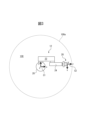
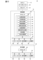
- FIG. 2 is a block diagram of the robot system shown in FIG. 1 . 2 shows an example of an allowable operating range.
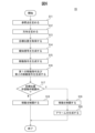
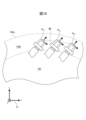
- 3 is a flowchart showing an example of an operation flow of the robot system shown in FIG. 2 . The robot is shown positioned within the proximity region.
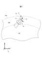
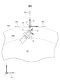
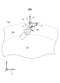
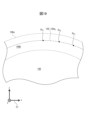
- 5 is a flowchart showing an example of the process of step S5 in FIG. 4. 7 shows the reference points set in step S11 in FIG. 6 shows a motion range coordinate system, a first direction, and a second direction set in step S12 in FIG. 8 shows the target position acquired in step S13 in FIG. An example of an image generated as a notification signal in step S14 in FIG. 6 is shown.
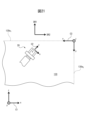
- FIG. 7 shows the first and second movement commands generated in step S16 in FIG. 6.
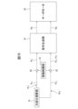
- FIG. 7 is a block diagram showing a schematic diagram of a signal transmission path in the movement restriction process executed in steps S18 and S19 in FIG. 6 .
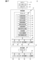
- FIG. 2 is a block diagram showing other functions of the robot system shown in FIG. 1 .
- 14 is a flowchart showing an example of step S5 executed by the robot system shown in FIG. 13.
- 15 shows the first force component and the second force component calculated in step S21 in FIG. 14.
- FIG. 15 is a block diagram showing a schematic diagram of a signal transmission path in the movement restriction process executed in steps S22 to S25 in FIG. 14.
- FIG. 2 is a block diagram showing still another function of the robot system shown in FIG. 1 .
- the robot's position and movement path during the restricted movement are shown. This indicates the newly established allowable operating range.
- Another example of the allowable operating range is shown. 21 shows a first direction and a second direction that are set based on the boundaries of the allowable operating range shown in FIG. 20 .
- the robot system 10 includes a robot 12, a control device 14, and a teaching device 16.
- the robot 12 is a vertical articulated robot and has a robot base 18, a rotating body 20, a lower arm 22, an upper arm 24, a wrist 26, and an end effector 28.
- the robot base 18 is fixed to the floor of a work cell or on an automated guided vehicle (AGV).
- the rotating body 20 is mounted on the robot base 18 so as to be rotatable around a vertical axis.
- the lower arm 22 is mounted on the rotating body 20 so that its base end can rotate around a horizontal axis.
- the upper arm 24 has a base end rotatably attached to the tip of the lower arm 22.
- the wrist 26 has a wrist base 26a attached to the tip of the upper arm 24 so as to be rotatable around two mutually perpendicular axes, and a wrist flange 26b rotatably attached to the wrist base 26a.
- the end effector 28 is detachably attached to the wrist flange 26b.
- the end effector 28 is, for example, a robot hand, a welding torch, a cutting tool, or a laser processing head, and performs a predetermined task (work handling, welding, cutting, or laser processing) on a workpiece (not shown).
- Each component of the robot 12 (robot base 18, rotating body 20, lower arm 22, upper arm 24, wrist 26) is provided with a servo motor 30 ( Figure 2).
- These servo motors 30 rotate the drive shafts of the robot 12 according to commands from the control device 14, thereby rotating the movable components of the robot 12, such as the rotating body 20, lower arm 22, upper arm 24, wrist base 26a, and wrist flange 26b (i.e., end effector 28), around the drive shafts. This allows the robot 12 to move the workpiece W grasped by the end effector 28 to any position.
- the robot 12 is also provided with a force sensor 32 (FIG. 2) that detects a force F applied to the robot 12.
- the force sensor 32 may be, for example, a six-axis force sensor provided on any component of the robot 12 (e.g., the robot base 18 or the wrist 26), or a torque sensor provided on each of the drive axes of the robot 12 driven by the servo motor 30, and supplies detection data Df of the detected force F to the control device 14.
- a robot coordinate system C1 and a tool coordinate system C2 are set for the robot 12.
- the robot coordinate system C1 is a fixed coordinate system for controlling the operation of each movable component of the robot 12.
- the robot coordinate system C1 is set with respect to the robot base 18 so that its origin is located at the center of the robot base 18 and its z axis is parallel to (specifically, coincides with) the rotation axis of the rotating body 20.
- the tool coordinate system C2 is a moving coordinate system that defines the position of the end effector 28 in the robot coordinate system C1.
- the tool coordinate system C2 is set with respect to the end effector 28 so that its origin (so-called TCP) is located at the working position of the end effector 28 (workpiece gripping position, welding position, cutting position, or laser emission port). Note that the tool coordinate system C2 may be located at any position.
- the control device 14 When moving the end effector 28 in the robot coordinate system C1, the control device 14 sets a tool coordinate system C2 in the robot coordinate system C1 and generates a command for each servo motor 30 to place the end effector 28 at a position represented by the set tool coordinate system C2. In this way, the control device 14 can position the end effector 28 at any position in the robot coordinate system C1 by driving each servo motor 30. Note that in this document, "position" can refer to both position and orientation.
- the control device 14 is a computer having a processor 34, memory 36, an I/O interface 38, a display device 40, and an input device 42.
- the processor 34 has a CPU or a GPU, etc., and is communicatively connected to the memory 36, the I/O interface 38, the display device 40, and the input device 42 via a bus 43, and while communicating with these components, performs calculations to realize various functions described below.
- Memory 36 has RAM or ROM, etc., and temporarily or permanently stores various data.
- Memory 36 may be a non-transitory computer-readable recording medium, such as a semiconductor memory, a magnetic recording medium, or an optical recording medium.
- I/O interface 38 has, for example, an Ethernet (registered trademark) port, a USB port, an optical fiber connector, or an HDMI (registered trademark) terminal, and communicates data with external devices via wired or wireless communication under instructions from processor 34.
- the display device 40 has a liquid crystal display or an organic EL display, etc., and visibly displays various data under instructions from the processor 34.
- the input device 42 has a push button, switch, keyboard, mouse, touch panel, etc., and accepts data input from an operator.
- the display device 40 and the input device 42 may be integrated into the housing of the control device 14, or may be connected to the I/O interface 38 as a computer (PC, etc.) separate from the housing of the control device 14.
- the teaching device 16 teaches the robot 12 how to move.
- the teaching device 16 is a computer having a processor 44, a memory 46, an I/O interface 48, a display device 50, and an input device 52.
- the teaching device 16 may be any type of computer, such as a teaching pendant or a notebook or tablet PC.
- the processor 44 is communicatively connected to the memory 46, the I/O interface 48, the display device 50, and the input device 52 via the bus 53. Note that the configurations of the processor 44, the memory 46, the I/O interface 48, the display device 50, and the input device 52 are similar to those of the processor 34, the memory 36, the I/O interface 38, the display device 40, and the input device 42 described above, and therefore will not be described again.
- the processor 34 of the control device 14 is configured to be able to execute a jog mode MD1 and a direct teach mode MD2 as the operation modes MD of the robot 12.
- the processor 34 moves the movable component of the robot 12 in the direction input by the operator to the input device 52 in accordance with a jog command Cj input by the operator operating the input device 52 of the teaching device 16.
- the processor 34 moves any movable component of the robot 12 (e.g., the wrist 26 or the end effector 28) to which an operating force Fh is applied in the direction of the operating force Fh, according to the operating force Fh applied by the operator.
- the operator can operate the input device 42 of the teaching device 16 to select the jog mode MD1 or the direct teach mode MD2 as the operation mode MD.
- an allowable operating range 100 is determined in advance for the robot 12.
- An example of the allowable operating range 100 is shown in FIG. 3.
- the allowable operating range 100 is determined as a substantially circular (e.g., cylindrical) range within a predetermined distance from the robot base 18 (i.e., the origin of the robot coordinate system C1).
- the outer edge of this allowable operating range 100 is defined by a cylindrical surface-shaped boundary 100a, and the processor 34 restricts the movement of the robot 12 outside the allowable operating range 100.
- the processor 34 starts the flow of FIG. 4 when it receives an operation start command from an operator, a higher-level controller, or the computer program PG.
- the robot 12 i.e., the end effector 28
- the allowable operating range 100 is within the allowable operating range 100.
- step S1 the processor 34 determines whether or not a command to move the robot 12 has been received.
- the processor 34 determines YES when the above-mentioned jog command Cj is received from the teaching device 16.
- the processor 34 continuously (e.g., periodically) calculates the magnitude and direction of the operating force Fh applied by the operator to the movable component of the robot 12 to move the robot 12, based on the detection data Df of the force sensor 32.
- the processor 34 functions as a force acquisition unit 62 (FIG. 2) that acquires the operating force Fh based on the detection data Df. Then, the processor 34 determines YES when the acquired operating force Fh exceeds a predetermined threshold value Fth (Fh ⁇ Fth). If the processor 34 determines YES, it proceeds to step S2, whereas if the processor 34 determines NO, it proceeds to step S6.
- a command joing command Cj or operating force Fh
- step S2 the processor 34 acquires the current position Pc of the robot 12. Specifically, the processor 34 acquires the coordinate Qc (xc, yc, zc) in the robot coordinate system C1 of the origin of the tool coordinate system C2 at this time point as position data of the current position Pc, based on the detection data Dr of a rotation detection sensor ( encoder , Hall element , etc. ) that detects the rotational position (or rotational angle) of each servo motor 30 at this time point. In this way, the processor 34 functions as a position acquisition unit 64 (FIG. 2) that acquires the current position Pc of the robot 12.
- a rotation detection sensor encoder , Hall element , etc.
- step S3 the processor 34 determines whether the robot 12 is within a proximity region 100b that is close to the boundary 100a of the allowable operating range 100.
- This proximity region 100b is determined in advance by the operator with the boundary 100a of the allowable operating range 100 as a reference.
- An example of the proximity region 100b is shown in FIG. 5.
- the proximity region 100b is determined such that the distance d from the boundary 100a to the inside of the allowable operating range 100 (e.g., the origin of the robot coordinate system C1) is in the range 0 ⁇ d ⁇ d1.
- step S2 determines NO and proceeds to step S4
- step S5 shows an example of the position of the robot 12 (end effector 28) when the determination in step S3 is YES.
- step S4 the processor 34 causes the robot 12 to perform a normal operation.
- the processor 34 moves the end effector 28 of the robot 12 in accordance with the jog command Cj received in the most recent step S1.
- the processor 34 moves the end effector 28 to which the operating force Fh has been applied in the direction of the operating force Fh obtained in the most recent step S1.
- step S5 the processor 34 executes a movement restriction process. This step S5 will be described with reference to FIG. 6.
- step S11 the processor 34 determines a point on the boundary 100a that is close to the current position Pc obtained in the most recent step S2 as a reference point Pr.
- the processor 34 identifies a point Pr on the boundary 100a at which the distance ⁇ from the most recently acquired current position Pc is the smallest.
- Fig. 7 shows a point Pr at which the distance ⁇ is the minimum value ⁇ 0.
- the processor 34 sets this point Pr as a reference point Pr, and acquires the coordinates Qr ( xr , yr , zr ) of the reference point Pr in the robot coordinate system C1.
- the processor 34 functions as a reference point setting unit 66 (Fig. 2) that sets the reference point Pr.
- step S12 the processor 34 determines a first direction DR1 toward the outside of the allowable operating range 100 and a second direction DR2 perpendicular to the first direction DR1, based on the current position Pc acquired in the previous step S2 and the boundary 100a of the allowable operating range 100 adjacent to the current position Pc.
- the processor 34 determines the first direction DR1 and the second direction DR2 based on the reference point Pr determined on the boundary 100a adjacent to the current position Pc in the previous step S11.
- the processor 34 sets a motion range coordinate system C3, which defines the first direction DR1 and the second direction DR2, in the robot coordinate system C1.
- the origin of the motion range coordinate system C3 is located at the reference point Pr determined in the previous step S11.
- the y axis of the motion range coordinate system C3 is parallel to the normal direction of the boundary 100a at the reference point Pr, and the positive y axis is directed outward from the allowable motion range 100 (i.e., in the direction away from the origin of the robot coordinate system C1).
- the z axis of the motion range coordinate system C3 may be parallel to the z axis of the robot coordinate system C1.
- the processor 34 sets a motion range coordinate system C3 with the reference point Pr as its origin.
- the y-axis direction of this motion range coordinate system C3 defines a first direction DR1
- the x-axis direction and z-axis direction (in other words, the xz plane) of the motion range coordinate system C3 define a second direction DR2. That is, in this embodiment, the first direction DR1 is parallel to the normal direction of the boundary 100a at the reference point Pr.
- the processor 34 acquires coordinates Qo ( xr , yr , zr , wo , po , ro ) in the robot coordinate system C1 of the set motion range coordinate system C3.
- ( xr , yr , zr ) indicate the coordinates of the origin (i.e., reference point Pr) of the movement range coordinate system C3 in the robot coordinate system C1
- ( wo , p , ro ) indicate the attitude (i.e., the direction of each axis) of the movement range coordinate system C3 with respect to the robot coordinate system C1.
- the processor 34 determines the first direction DR1 and the second direction DR2 by setting the movement range coordinate system C3 based on the reference point Pr determined based on the current position Pc and the boundary 100a. Therefore, the processor 34 functions as a direction setting unit 68 (FIG. 2) that determines the first direction DR1 and the second direction DR2 based on the current position Pc and the boundary 100a.
- step S13 the processor 34 obtains a target position Pt to which the robot 12 is to be moved from the current position Pc obtained in the most recent step S2.
- the processor 34 calculates the target position Pt based on the jog command Cj received in the most recent step S1 and the current position Pc obtained in the most recent step S2.
- the jog command Cj includes information that specifies the movement direction DRm and the movement amount ⁇ in which the end effector 28 is to be moved.
- the processor 34 calculates the target position Pt based on the operating force Fh acquired in the most recent step S1 and the current position Pc acquired in the most recent step S2.
- a relationship R Fh_ ⁇ between the magnitude of the operating force Fh and the movement amount ⁇ by which the robot 12 (e.g., the end effector 28) is moved according to the operating force Fh may be determined in advance and stored in the memory 36 (or 46) in advance.
- the processor 34 applies the operating force Fh obtained in the most recent step S1 to the relationship R Fh_ ⁇ (i.e., a formula) to obtain a corresponding movement amount ⁇ .
- the processor 34 then calculates a target position Pt based on the obtained movement amount ⁇ , the direction of the operating force Fh obtained in the most recent step S1, and the current position Pc.
- An example of the target position Pt obtained in this manner is shown in FIG. 9.
- the processor 34 functions as a position calculation unit 70 ( Figure 2) that calculates the target position Pt.
- step S14 the processor 34 generates a notification signal Sn.
- This notification signal Sn notifies the operator of the movement direction DRm (FIG. 9) from the current position Pc to the target position Pt, and the distance ⁇ between the target position Pt and the boundary 100a.
- the processor 34 generates an image 110 shown in FIG. 10 as the notification signal Sn.
- This image 110 is a graphical user interface (GUI) for visually notifying the operator of the movement direction DRm and the distance ⁇ .
- GUI graphical user interface
- the image 110 shows a three-dimensional display of the robot model 12M (e.g., a 3D CAD model) that models the robot 12, and the allowable operating range 100 (boundary 100a).
- the image 110 also shows the operating range coordinate system C3 (i.e., the first direction DR1 and the second direction DR2) that was set in the most recent step S12, superimposed on the robot model 12M placed at the current position Pc, together with the reference point Pr.
- the operating range coordinate system C3 i.e., the first direction DR1 and the second direction DR2
- the image 110 displays the target position Pt and movement direction DRm obtained in the immediately preceding step S13 superimposed on the robot model 12M, and also displays the distance ⁇ between the target position Pt and the boundary 100a in the distance display field 112.
- the processor 34 displays the generated image 110 on the display device 40 (or 50). In this way, the processor 34 functions as the notification signal generation unit 72 ( Figure 2) that generates the notification signal Sn (image 110).
- the processor 34 may further display the distance ⁇ between the current position Pc and the boundary 100a in the distance display field 112.
- the processor 34 may further display at least one of the robot coordinate system C1 and the tool coordinate system C2, the coordinate Qc of the current position Pc, the coordinate Qr of the reference point Pr, and the coordinate Qo of the motion range coordinate system C3 in the image 110.
- the processor 34 may display only either the movement direction DRm or the distance ⁇ in the image 110.
- the processor 34 may generate an audio signal that explains the movement direction DRm or the distance ⁇ as the notification signal Sn in place of the image 110.
- step S15 the processor 34 generates a movement command Cm for moving the robot 12 (end effector 28) from the current position Pc to the target position Pt, outside the allowable operating range 100.
- the movement command Cm includes, for example, a position command Cm p , a speed command Cm v , a torque command Cm q , or an acceleration command Cm a , and drives each servo motor 30 of the robot 12 to move the end effector 28 to the target position Pt.
- the processor 34 functions as a command generator 74 ( FIG. 2 ) that generates the movement command Cm.
- step S16 the processor 34 functions as the command generator 74 and generates a first movement command Cm1 and a second movement command Cm2 based on the motion range coordinate system C3 set in the most recent step S12.
- the first movement command Cm1 is a command for moving the robot 12 (specifically, the end effector 28) in the first direction DR1 (i.e., the y-axis positive direction of the motion range coordinate system C3) set in the most recent step S12.
- the second movement command Cm2 is a command for moving the end effector 28 in the second direction DR2 (i.e., the direction along the x-z plane of the motion range coordinate system C3) set in the most recent step S12.
- the processor 34 calculates a component Cm1 of the movement command Cm in the positive y-axis direction (i.e., the first direction DR1) of the movement command Cm in the movement range coordinate system C3 based on the coordinate Qo of the movement range coordinate system C3 in the robot coordinate system C1 and the movement command Cm generated in the most recent step S15.
- This calculation will be described with reference to Fig. 11.
- the vector Cm represents the movement vector of the end effector 28 based on the movement command Cm generated in step S15.
- the movement vector based on the movement command Cm is represented in the motion range coordinate system C3 set in the most recent step S12.
- the processor 34 transforms the component Cm1 represented in the motion range coordinate system C3 into the robot coordinate system C1, and generates it as the first movement command Cm1 .
- the first movement command Cm1 includes, for example, a first position command Cmp1 , a first velocity command Cmv1 , a first torque command Cmq1 , or a first acceleration command Cmal .
- the first position command Cmp1 is a command for moving the end effector 28 in the positive direction of the y axis of the motion range coordinate system C3 (first direction DR1) to a position Pty (FIG. 11) on the y coordinate of the motion range coordinate system C3, which is the target position Pt .
- the first velocity command Cm v1 includes a velocity command value V1 that specifies a velocity V1 at which the end effector 28 moves in the positive direction of the y-axis of the motion range coordinate system C3 to the position Pty .
- the first torque command Cm q1 includes a torque command value q1 that specifies a torque q1 that drives each servo motor 30 when moving the end effector 28 to the position Pty .
- the first acceleration command Cm a1 includes an acceleration command value a1 that specifies an acceleration a1 when moving the end effector 28 to the position Pty .
- the processor 34 calculates a component Cm2 of the movement command Cm in the xz plane of the motion range coordinate system C3 (i.e., the second direction DR2) based on the coordinate Qo and the movement command Cm.
- the processor 34 transforms the component Cm2 expressed in the motion range coordinate system C3 into the robot coordinate system C1 to generate a second movement command Cm2 .
- the second movement command Cm2 includes a second position command Cmp2 , a second velocity command Cmv2 , a second torque command Cmq2 , a second acceleration command Cma2 , or the like.
- the second position command Cm p2 is a command for moving the end effector 28 in the positive direction of the x-axis of the motion range coordinate system C3 (second direction DR2) to a position Pt x of the x-coordinate of the target position Pt in the motion range coordinate system C3.
- the second velocity command Cm v2 includes a velocity command value V2 that specifies a velocity V2 for moving the end effector 28 in the positive direction of the x-axis of the motion range coordinate system C3 to the position Pt x .
- the second torque command Cm q2 includes a torque command value q2 that defines the torque q2 that drives each servo motor 30 when moving the end effector 28 to the position Pt x .
- the second acceleration command Cm a2 includes an acceleration command value a2 that defines the acceleration a2 when moving the end effector 28 to the position Pt x .
- the processor 34 functions as a command generator 74 and generates the first movement command Cm 1 and the second movement command Cm 2 based on the motion range coordinate system C3.
- step S17 the processor 34 determines whether or not the target position Pt obtained in the most recent step S13 is outside the allowable operating range 100. If the target position Pt is outside the allowable operating range 100, the processor 34 determines YES and proceeds to step S19, whereas if the processor determines NO, the processor 34 proceeds to step S18.
- step S18 the processor 34 restricts the movement of the robot 12. Specifically, the processor 34 restricts the movement of the robot 12 (specifically, the end effector 28) by reducing the command values (e.g., the speed command value V1, the torque command value q1, and the acceleration command value a1) of the first movement command Cm1 generated in the most recent step S16.
- the command values e.g., the speed command value V1, the torque command value q1, and the acceleration command value a1 of the first movement command Cm1 generated in the most recent step S16.
- the processor 34 may multiply the speed command value V1, torque command value q1, or acceleration command value a1 included in the first movement command Cm1 by a predetermined coefficient ⁇ (e.g., ⁇ 1) (i.e., ⁇ V1, ⁇ q1, or ⁇ a1) to reduce the command value V1, q1, or a1.
- ⁇ e.g., ⁇ 1
- the processor 34 may limit the movement of the end effector 28 in the first direction DR1 by correcting the first position command Cm p1 included in the first movement command Cm 1.
- the processor 34 may correct the first position command Cm p1 so that the target position Pty in the first direction DR1 of the end effector 28 according to the first position command Cm p1 is inside the boundary 100a.
- the processor 34 performs arithmetic processing such as multiplication of the coefficient ⁇ or correction of the position command Cm p1 on the first movement command Cm 1 generated in the above-mentioned step S15 to change it to a first movement command Cm 1 ', and supplies it to each servo motor 30. This makes it possible to restrict the movement of the robot 12 based on the first movement command Cm 1 .
- the processor 34 permits the movement of the robot 12 according to the second movement command Cm2 .
- the processor 34 supplies the second movement command Cm2 generated in the above-mentioned step S15 to each servo motor 30 without making any changes. That is, in this case, the processor 34 supplies the second position command Cm p2 , the second speed command Cm v2 (speed command value V2), the second torque command Cm q2 (torque command value q2), or the second acceleration command Cm a2 (acceleration command value a2) included in the second movement command Cm2 to each servo motor 30 without making any changes.
- the command value V2, q2 or a2 of the second movement command Cm2 does not decrease, and the processor 34 moves the end effector 28 in the second direction DR2 (in the example of Figure 11, the positive x-axis direction of the operating range coordinate system C3) in accordance with the second movement command Cm2 (command value V2, q2 or a2).
- the processor 34 may set the speed command value V2, torque command value q2, or acceleration command value a2 included in the second movement command Cm2 to a constant Vc ( ⁇ V2), qc ( ⁇ q2), or ac ( ⁇ a2) that is equal to or greater than the value acquired in step S16, to provide the second movement command Cm2 ' to each servo motor 30. That is, in this case, the processor 34 moves the end effector 28 in the second direction DR2 at a constant speed Vc, torque qc, or acceleration ac.
- the processor 34 may multiply the speed command value V2, the torque command value q2, or the acceleration command value a2 included in the second movement command Cm2 by a predetermined coefficient ⁇ (i.e., ⁇ V2, ⁇ q2, or ⁇ a2) to obtain the second movement command Cm2 ', and supply it to each servo motor 30.
- a predetermined coefficient ⁇ i.e., ⁇ V2, ⁇ q2, or ⁇ a2
- the command value ⁇ V2, ⁇ q2, or ⁇ a2 of the second movement command Cm2 does not decrease according to the distance ⁇ , but rather, the movement of the end effector 28 in the second direction DR2 is promoted (accelerated) as the end effector 28 approaches the boundary 100a.
- the processor 34 permits (or does not restrict) the movement of the robot 12 according to the second movement command Cm2 .
- the processor 34 functions as a movement restriction unit 76 (FIG. 2) that restricts the movement of the robot 12 according to the first movement command Cm1 while permitting the movement of the robot 12 according to the second movement command Cm2 .
- the processor 34 proceeds to step S6 in FIG. 4.
- step S19 the processor 34 functions as the movement restriction unit 76 to restrict the movement of the robot 12. Specifically, the processor 34 prohibits the movement of the robot 12 in the first direction DR1. For example, the processor 34 prohibits the movement of the robot 12 in the first direction DR1 by setting the speed command value V1, the torque command value q1, or the acceleration command value a1 included in the first movement command Cm1 to zero . Alternatively, the processor 34 may correct the first position command Cm p1 included in the first movement command Cm1 so that the target position Pty in the first direction DR1 according to the first position command Cm p1 included in the first movement command Cm1 is on (or inside) the boundary 100a.
- the processor 34 changes the first movement command Cm1 generated in the above-mentioned step S15 to a first movement command Cm1 ' by executing calculation processing such as changing the command value V1, q1, or a1 to zero or correcting the position command Cmp1 , and supplies the first movement command Cm1 ' to each servo motor 30.
- This makes it possible to prohibit the movement of the end effector 28 in the first direction DR1.
- the processor 34 permits (or does not restrict) the movement of the robot 12 based on the second movement command Cm2 , similar to the above-mentioned step S18.
- the movement restriction process in steps S18 and S19 is shown in FIG. 12.
- the first movement command Cm1 generated by the command generating unit 74 in step S15 is sent to the first signal processing line PL1 and input to the calculator 80 by the movement restricting unit 76.
- the movement restricting unit 76 performs a calculation process for movement restriction on the first movement command Cm1 , such as multiplication by a coefficient ⁇ , and changes it to a first movement command Cm1 '.
- the first movement command Cm1 ' is output to the servo motor 30, and the servo motor 30 restricts the movement of the robot 12 in accordance with the first movement command Cm1 '.
- the above-mentioned restriction is applied to the movement of the robot 12 according to the first movement command Cm1 .
- the second movement command Cm2 generated by the command generation unit 74 in step S15 is sent to a second signal processing line PL2 separate from the first signal processing line PL1, and input to a calculator 82 by the movement restriction unit 76. Then, in steps S18 or S19, the movement restriction unit 76 supplies the second movement command Cm2 to each servo motor 30 without making any changes, or performs calculation processing such as multiplication by a coefficient ⁇ to generate a second movement command Cm2 ' and supplies it to each servo motor 30.
- the robot 12 moves in accordance with the second movement command Cm2 .
- the first movement command Cm1 and the second movement command Cm2 generated by the command generating unit 74 are sent to separate signal processing lines PL1 and PL2, respectively, and the movement restricting unit 76 performs different signal processing on each of them.
- step S20 the processor 34 generates an alarm AL.
- the processor 34 generates an image or sound alarm AL stating, "Movement of the robot outside the allowable operating range is prohibited.”
- the processor 34 displays the generated alarm AL on the display device 40 (or 50) or outputs it through a speaker (not shown).
- control device 14, the teaching device 16, or the robot 12 may be provided with a light-emitting device (revolving light, LED lamp, etc.), and the processor 34 may generate an alarm AL that causes the light-emitting device to emit light.
- teaching device 16 or the robot 12 may be provided with a vibrator (or a tactile generating device), and the processor 34 may generate an alarm AL that causes the vibrator to vibrate.
- the processor 34 proceeds to step S6 in FIG. 4.
- step S6 the processor 34 determines whether or not an operation end start command has been received from the operator, the higher-level controller, or the computer program PG. If the processor 34 determines YES, it ends the flow in FIG. 4, whereas if the processor determines NO, it returns to step S1.
- the processor 34 functions as the force acquisition unit 62, position acquisition unit 64, reference point setting unit 66, direction setting unit 68, position calculation unit 70, notification signal generation unit 72, command generation unit 74, and movement restriction unit 76 to restrict the movement of the robot 12 toward the outside of the allowable operating range 100. Therefore, the force acquisition unit 62, position acquisition unit 64, reference point setting unit 66, direction setting unit 68, position calculation unit 70, notification signal generation unit 72, command generation unit 74, and movement restriction unit 76 constitute a device 60 ( Figure 2) that restricts the movement of the robot 12 toward the outside of the allowable operating range 100.
- the position acquisition unit 64 acquires the current position Pc of the robot 12 (step S2), and the direction setting unit 68 determines a first direction DR toward the outside of the allowable operating range 100 and a second direction DR2 perpendicular to the first direction DR1 based on the current position Pc acquired by the position acquisition unit 64 and the boundary 100a of the allowable operating range 100 adjacent to the current position Pc (step S12).
- the command generation unit 74 generates a first movement command Cm1 for moving the robot 12 in a first direction DR1 determined by the direction setting unit 68, and a second movement command Cm2 for moving the robot 12 in a second direction DR2 determined by the direction setting unit 68. Then, the movement restriction unit 76 restricts the movement of the robot 12 according to the first movement command Cm1 , while permitting the movement of the robot 12 according to the second movement command Cm2 (steps S18, S19).
- This configuration reliably prevents the robot 12 from moving outside the allowable operating range 100, ensuring the safety of the robot 12's operation.
- the operator may wish to move the robot 12 (end effector 28) along the boundary 100a of the allowable operating range 100 (i.e., in the second direction DR2). In such a case, the operator can move the robot 12 effectively.
- the reference point setting unit 66 sets a point Pr on the boundary 100a close to the current position Pc acquired by the position acquisition unit 64 as a reference point Pr (step S11). Then, the direction setting unit 68 sets a first direction DR1 and a second direction DR2 based on the reference point Pr set by the reference point setting unit 66 (step S12). With this configuration, the first direction DR1 and the second direction DR2 can be appropriately set on the boundary 100a according to the current position Pc of the robot 12. As a result, the movement of the robot 12 in the first direction DR1 according to the first movement command Cm1 can be appropriately restricted.
- the reference point setting unit 66 sets the point Pr on the boundary 100a at which the distance ⁇ from the current position Pc is the smallest as the reference point Pr.
- the reference point Pr that is the basis for the first direction DR1 and the second direction DR2 can be appropriately set in correspondence with the current position Pc.
- the direction setting unit 68 sets the normal direction of the boundary 100a at the reference point Pr set by the reference point setting unit 66 as the first direction DR1. With this configuration, even if the boundary 100a is curved (e.g., circular), for example, the first direction DR1 can be appropriately set in correspondence with the current position Pc of the robot 12.
- the direction setting unit 68 sets a motion range coordinate system C3 having a first axis (y-axis) that defines the first direction DR1 and a second axis (x-axis, z-axis) that defines the second direction DR1, with the reference point Pr set by the reference point setting unit 66 as the origin.
- the command generating unit 74 then generates a first movement command Cm1 in the direction of the first axis (y-axis direction) and a second movement command Cm2 in the direction of the second axis (direction of the x-z plane) based on the motion range coordinate system C3.
- the calculation processes of the first movement command Cm1 and the second movement command Cm2 can be executed in parallel independently of each other based on the motion range coordinate system C3, thereby improving the efficiency of the calculation process.
- the command generator 74 generates a movement command Cm for moving the robot 12 outside the allowable operating range 100 (step S15), generates a component Cm1 of the movement command Cm in the first direction DR1 as the first movement command Cm1 , and generates a component Cm2 of the movement command Cm in the second direction DR1 as the second movement command Cm2 .
- the first movement command Cm1 and the second movement command Cm2 can be generated from the movement command Cm using a relatively simple algorithm. This can speed up the calculation process for generating the first movement command Cm1 and the second movement command Cm2 .
- the first movement command Cm1 and the second movement command Cm2 include command values V1 and V2, a1 and a2, or q1 and q2 that define the velocity V1 and V2 of the robot 12, the acceleration a1 and a2 of the robot, or the torque q1 and q2 that drive the robot 12.
- the movement limiting unit 76 limits the movement of the robot 12 based on the first movement command Cm1 by reducing the command value V1, a1, or q1 of the first movement command Cm1 .
- the movement limiting unit 76 permits the movement of the robot 12 according to the second movement command Cm2 without reducing the command values V2, a2, or q2 of the second movement command Cm2 .
- the movement limit of the robot 12 according to the first movement command Cm1 can be realized by a simple algorithm, and more diverse movement limits can be designed, for example, by appropriately setting the above-mentioned coefficient ⁇ .
- the movement limiting unit 76 may slightly reduce the command values V2, a2, or q2 of the second movement command Cm2 to an extent that the movement of the robot 12 according to the second movement command Cm2 is permitted.
- the position calculation unit 70 determines the target position Pt to which the robot 12 is to be moved from the current position Pc, and the notification signal generation unit 72 generates a notification signal Sn that notifies the movement direction DRm from the current position Pc to the target position Pt, or the distance ⁇ between the target position Pt and the boundary 100a (step S14).
- the operator can intuitively recognize the movement direction DRm or the distance ⁇ .
- the movement restriction unit 76 prohibits the movement of the robot 12 in the first direction DR1 (step S19). This configuration can reliably prevent the robot 12 from moving outside the allowable operating range 100.
- the processor 34 may first execute steps S13 and S15, then execute steps S11, S12, and S14, and then execute steps S16 to S20 in sequence.
- ⁇ the minimum distance from the current position Pc
- the processor 34 may determine the intersection P between the direction of one axis of the tool coordinate system C2 at this time (e.g., the z-axis of the tool coordinate system C2 in FIG. 9) and the boundary 100a as the reference point Pr.
- the processor 34 may determine the movement direction Dm (FIG. 9) in step S13 or S15, and then in step S11, determine the intersection P between the determined movement direction Dm and the boundary 100a as the reference point Pr.
- the processor 34 determines the normal direction of the boundary 100a at the reference point Pr as the first direction DR1 (the y-axis direction of the working range coordinate system C3) in step S12 described above.
- the processor 34 may determine the first direction DR1 (the y-axis direction of the working range coordinate system C3) by any other algorithm.
- the processor 34 may determine the direction from the origin of the tool coordinate system C2 at this time (FIG. 8) to the point Pr on the boundary 100a at which the distance ⁇ from the origin is the smallest as the first direction DR1 (the positive y-axis direction of the working range coordinate system C3).
- the processor 34 sets the motion range coordinate system C3 in step S12. However, this is not limiting, and the processor 34 may set the first direction DR1 and the second direction DR2 based on the reference point Pr in step S12 without setting the motion range coordinate system C3.
- step S14 may be omitted from the flow of FIG. 6. That is, in this case, the notification signal generating unit 72 may be omitted from the device 60. Also, step S20 may be omitted from the flow of FIG. 6.
- the processor 34 is capable of executing the jog mode MD1 and the direct teach mode MD2. However, this is not limiting, and the processor 34 may be capable of executing only the jog mode MD1 without executing the direct teach mode MD2. That is, in this case, the force sensor 32 may be omitted from the robot 12, and the force acquisition unit 62 may be omitted from the device 60.
- the processor 34 functions as the device 60, which further includes the functions of a force component calculation unit 78.
- the functions of the robot system 10 shown in FIG. 13 will be described with reference to FIG. 4 and FIG. 14.
- the processor 34 executes the flow of FIG. 4 under the above-mentioned direct teach mode MD2.
- step S1 the processor 34 determines whether or not a command to move the robot 12 (operational force Fh) has been received based on the operational force Fh acquired by functioning as the force acquisition unit 62.
- the processor 34 executes the flow of FIG. 14 as step S5 (movement restriction process). Note that in the flow shown in FIG. 14, processes similar to those in the flow of FIG. 6 are given the same step numbers, and duplicate explanations will be omitted.
- step S21 the processor 34 obtains a first force component Fh1 in a first direction DR1 and a second force component Fh2 in a second direction DR2 of the operating force Fh obtained in the most recent step S1.
- the calculation of the force components will be described with reference to FIG.
- the vector (i.e., magnitude and direction) of the operational force Fh acquired in the most recent step S1 is represented in the operational range coordinate system C3 set in the most recent step S12.
- the processor 34 calculates the component Fh1 represented in the operational range coordinate system C3 based on the coordinate Qo of the operational range coordinate system C3 in the robot coordinate system C1 and the operational force Fh acquired in the most recent step S1 , converts it into the robot coordinate system C1, and acquires it as the first force component Fh1 .
- the processor 34 calculates the component Fh2 expressed in the motion range coordinate system C3 based on the coordinate Qo and the operational force Fh, converts it into the robot coordinate system C1, and obtains it as the second force component Fh2 . In this way, the processor 34 functions as a force component calculation unit 78 ( FIG.
- step S17 the processor 34 executes step S17. If the result of the determination in step S17 is NO, in step S22, the processor 34 functions as the movement restriction unit 76 to restrict the movement of the robot 12. Specifically, the processor 34 reduces the first force component Fh1 calculated in the most recent step S21, thereby restricting the movement of the robot 12 according to the first movement command Cm1 generated in a later step S23.
- the processor 34 may reduce the first force component Fh1 by multiplying it by a predetermined coefficient ⁇ (e.g., ⁇ 1) (i.e., ⁇ Fh1 ), thereby changing it to the first force component Fh1 '.
- ⁇ e.g., ⁇ 1
- the processor 34 does not reduce the second force component Fh2 , and allows (or does not restrict) the movement of the robot 12 based on the second movement command Cm2 generated in a later step S23.
- the processor 34 does not change the second force component Fh2 .
- the processor 34 may change the second force component Fh2 to the second force component Fh2 ' by setting the second force component Fh2 to a constant Fhc ( ⁇ Fh2 ) that is equal to or greater than the value calculated in step S21.
- the second force component Fh2 does not decrease according to the distance ⁇ , but rather, as the end effector 28 approaches the boundary 100a, the movement of the end effector 28 in the second direction DR2 by the second movement command Cm2 generated in a later step S23 is promoted.
- the processor 34 permits (or does not restrict) the movement of the robot 12 by the second movement command Cm2 .
- the processor 34 also generates a second movement command Cm2 in response to the second force component Fh2 , Fhc, or ⁇ Fh2 obtained as a result of the previous step S22. Since the second force component Fh2 determined in step S21 is not reduced in the previous step S22, the movement of the end effector 28 in the second direction DR2 by the second movement command Cm2 generated at this time is permitted (or is not restricted).
- the processor 34 also generates a second movement command Cm2 in response to the second force component Fh2 , Fhc, or ⁇ Fh2 obtained as a result of the immediately preceding step S24. This allows (or does not restrict) the movement of the end effector 28 in the second direction DR2. After step S25, the processor 34 proceeds to the above-mentioned step S20.
- the movement restriction process in steps S21 to S25 is shown diagrammatically in Fig. 16.
- the first force component Fh1 calculated by the force component calculation unit 78 in step S21 is sent to the first signal processing line PL1 and input to the calculator 80 by the movement restriction unit 76.
- the movement restriction unit 76 performs calculation processing for movement restriction on the first force component Fh1 , such as multiplication by a coefficient ⁇ , and changes it to a first force component Fh1 '.
- the first force component Fh 1 ' is input to the command generating unit 74, and in step S23 or S25, the command generating unit 74 generates a first movement command Cm 1 in accordance with the first force component Fh 1 ' and outputs it to each servo motor 30.
- the movement of the robot 12 based on the first movement command Cm 1 thus generated is subject to the above-mentioned restrictions.
- the second force component Fh2 calculated by the force component calculation unit 78 in step S21 is sent to the second signal processing line PL2 and input to the calculator 82 by the movement limiting unit 76. Then, in steps S22 or S24, the movement limiting unit 76 supplies the second force component Fh2 to the command generating unit 74 without making any changes to it, or performs calculation processing such as multiplication by the coefficient ⁇ and supplies it to the command generating unit 74 as the second force component Fh2 '.
- step S23 or S25 the command generating unit 74 generates a second movement command Cm2 in response to the second force component Fh2 or Fh2 ' and supplies it to each servo motor 30.
- the second movement command Cm2 generated in this manner permits the robot 12 to move in the second direction DR2.
- the first force component Fh1 and the second force component Fh2 generated by the force component generating unit 78 are sent to separate signal processing lines PL1 and PL2, respectively, and different signal processes are performed for each of them by the movement limiting unit 76.
- the force acquisition unit 62 acquires an operational force Fh applied to the robot 12 to move the robot 12 based on the detection data Df of the force sensor 32 that detects the force F applied to the robot 12 (step S1).
- the force component calculation unit 78 determines the component Fh1 in the first direction DR1 of the operational force Fh acquired by the force acquisition unit 62 as a first force component Fh1 , and determines the component Fh2 in the second direction DR2 of the operational force Fh as a second force component Fh2 (step S21).
- the command generator 74 generates a first movement command Cm1 according to the first force component Fh1 calculated by the force component calculator 78, and generates a second movement command Cm2 according to the second force component Fh2 calculated by the force component calculator 78 (steps S23, S25).
- the robot 12 can be accurately moved in each of the first direction DR1 and the second direction DR2 by an amount corresponding to the operational force Fh.
- the movement limiting unit 76 limits the movement of the robot 12 according to the first movement command Cm1 by reducing the first force component Fh1 , while permitting the movement of the robot 12 according to the second movement command Cm2 without reducing the second force component Fh2 (steps S22, S24).
- the movement limit of the robot 12 according to the first movement command Cm1 can be realized by a simple algorithm, and more diverse movement limits can be designed by appropriately setting the coefficient ⁇ described above, for example.
- the movement limiting unit 76 may slightly reduce the second force component Fh2 to the extent that the movement of the robot 12 according to the second movement command Cm2 is permitted.
- the processor 34 functions as the device 60, which further includes the functions of an operating range setting unit 84.
- the processor 34 executes the flow of FIG. 6 or FIG. 14, and functions as a movement restriction unit 76 in the above-mentioned steps S18, S19, S22 or S24 to restrict the movement of the robot 12 (i.e., restricting movement in the first direction DR1 while allowing movement in the second direction DR2).
- Fig. 18 shows the current positions Pc 1 , Pc 2 , and Pc 3 of the end effector 28 acquired during the limited movement.
- the processor 34 sets a new allowable operating range 120 based on the current position Pc n acquired during the limited movement. As an example, the processor 34 sets the new allowable operating range 120 in the robot coordinate system C1 so as to pass through the current positions Pc 1 , Pc 2 , and Pc 3 .
- the processor 34 generates a movement path MP that passes through the current positions Pc1 , Pc2 , and Pc3 based on the current positions Pc1 , Pc2, and Pc3 , and sets a new allowable movement range 120 in the robot coordinate system C1 so as to be tangent to the generated movement path MP.
- the processor 34 functions as a movement range setting unit 84 (FIG. 17) that sets a new allowable movement range 120 based on the current position Pcn acquired during restricted movement.
- FIG. 19 An example of the allowable operating range 120 thus set is shown in FIG. 19. As shown in FIG. 19, the allowable operating range 120 is disposed inside the boundary 100a of the predetermined allowable operating range 100, and the boundary 120a of the allowable operating range 120 extends along (e.g., parallel to) the boundary 100a.
- the processor 34 stores data of the newly set allowable operating range 120 (e.g., coordinates in the robot coordinate system C1) in the memory 36 (or 46). The processor 34 may then execute the flow of FIG. 4 based on the new allowable operating range 120.
- the position acquisition unit 64 repeatedly acquires the current position Pc n of the robot 12 while the movement restriction unit 76 is restricting the movement of the robot 12. Then, the motion range setting unit 84 sets a new allowable motion range 120 based on the current position Pc n acquired by the position acquisition unit 64 during the restricted movement.
- a new allowable operating range 120 can be easily set from the position Pc n (or the movement path MP) of the robot 12 that has been moved with limited movement along the boundary 100a of the predetermined allowable operating range 100. This makes it possible to arbitrarily set various allowable operating ranges.
- the predetermined allowable operating range 100 is described as being circular (or cylindrical). However, this is not limited to this, and the allowable operating range 100 may be any shape, such as a polygon (rectangle, pentagon, etc.), a hemisphere, or a random shape consisting of multiple curved surfaces.
- the processor 34 determines the reference point Pr in step S11. However, this is not limiting, and the processor 34 can also determine the first direction DR1 and the second direction DR2 without determining the reference point Pr. This embodiment will be described with reference to Figures 20 and 21.
- a substantially rectangular allowable motion range 130 is determined in advance, and a boundary 130a of the allowable motion range 130 has boundaries 130a1 , 130a2 , 130a3 , and 130a4 that each define one side of the rectangle.
- a motion range coordinate system C3 is set in advance for the allowable motion range 130.
- the motion range coordinate system C3 is a coordinate system that defines the position of the allowable motion range 130 in the robot coordinate system C1.
- the movement range coordinate system C3 is set so that its origin is located on the intersection line of the boundaries 130a1 and 130a2 (i.e., one vertex of a rectangle), its x-axis is parallel to the boundaries 130a1 and 130a3 , its y-axis is parallel to the boundaries 130a2 and 130a4 , and its z-axis is parallel to the z-axis of the robot coordinate system C1.
- the coordinate Qo of the movement range coordinate system C3 in the robot coordinate system C1 is known.
- the processor 34 executes the flow shown in Fig. 4 based on the allowable operating range 130.
- the processor 34 starts the flow of step S5 in Fig. 6 or 14, it executes step S12 without executing step S11.
- the processor 34 functions as the direction setting unit 68 and determines a first direction DR1 toward the outside of the allowable operating range 130 and a second direction DR2 perpendicular to the first direction DR1 based on the current position Pc acquired in the most recent step S2 and the boundary 130a -1 of the allowable operating range 130 close to the current position Pc.
- the processor 34 identifies the boundary 130a1 that is closest to the current position Pc among the boundaries 130a1 , 130a2 , 130a3 , and 130a4 of the allowable operating range 130.
- the processor 34 determines, as a first direction DR1, the negative y-axis direction of the operating range coordinate system C3 that is parallel to the normal direction of the identified boundary 130a1 and points outward from the allowable operating range 130.
- the processor 34 determines, as a second direction DR2, the direction of the xz plane of the operating range coordinate system C3 that is perpendicular to the first direction DR1.
- the processor 34 defines the negative x-axis direction of the motion range coordinate system C3 as the first direction DR1, and defines the direction of the y-z plane of the motion range coordinate system C3 as the second direction.
- the first direction DR1 and the second direction can be defined as the x-axis direction or the y-axis direction of the motion range coordinate system C3 depending on the boundary 130a1 , 130a2 , 130a3 , or 130a4 that is close to the current position Pc.
- the processor 34 determines the first direction DR1 and the second direction DR2 based on the boundary 130a 1 close to the current position Pc, using the predetermined motion range coordinate system C3 as a reference. In this embodiment, the processor 34 then sequentially executes steps S13 to S20 in FIG. 6, or steps S13, S14, S21, S17, S22 to 25, and S20 in FIG. 14, using the motion range coordinate system C3 as a reference and based on the set first direction DR1 and second direction DR2. In this way, according to this embodiment, step S11 can be omitted from the flow in FIG. 4 or FIG. 6. That is, the reference point setting unit 66 can be omitted from the device 60.
- the processor 34 may execute the flow shown in FIG. 4 according to a computer program PG prestored in the memory 36 (or 46).
- the functions of the device 60 executed by the processor 34 i.e., the force acquisition unit 62, the position acquisition unit 64, the reference point setting unit 66, the direction setting unit 68, the position calculation unit 70, the notification signal generation unit 72, the command generation unit 74, the movement restriction unit 76, the force component calculation unit 78, and the motion range setting unit 84
- the functions of the device 60 executed by the processor 34 i.e., the force acquisition unit 62, the position acquisition unit 64, the reference point setting unit 66, the direction setting unit 68, the position calculation unit 70, the notification signal generation unit 72, the command generation unit 74, the movement restriction unit 76, the force component calculation unit 78, and the motion range setting unit 84
- the computer program PG may be functional modules realized by the computer program PG.
- the processor 34 executes the flow in FIG. 4 when teaching in the jog mode MD1 or the direct teach mode MD2.
- this is not limiting, and for example, the processor 34 may execute the flow in FIG. 4 when the operator and the robot 12 work together.
- the functions of the device 60 are described as being implemented in the control device 14. However, this is not limited to the above, and at least one of the functions of the device 60 may be implemented in the teaching device 16.
- the notification signal generation unit 72 may be implemented in the teaching device 16.
- the processor 44 of the teaching device 16 may function as the notification signal generation unit 72 to generate the image 110 shown in FIG. 10 and display it on the display device 50.
- at least one of the functions of the device 60 may be implemented in any computer (such as a PC) other than the control device 14 and the teaching device 16.
- a device 60 for restricting movement of a robot 12 toward the outside of a predetermined allowable operating range 100, 130 including: a position acquisition unit 64 for acquiring a current position Pc of the robot 12; a direction setting unit 68 for determining a first direction DR1 toward the outside and a second direction DR2 perpendicular to the first direction DR1 based on the current position Pc acquired by the position acquisition unit 64 and boundaries 100a, 130a of the allowable operating range 100, 130 adjacent to the current position Pc; a command generation unit 74 for generating a first movement command Cm1 for moving the robot 12 in the first direction DR1 determined by the direction setting unit 68 and a second movement command Cm2 for moving the robot 12 in the second direction DR2 determined by the direction setting unit 68; and a movement limiting unit 76 that allows movement of the robot 12 by the robot arm 2 .
- the device 60 described in aspect 1 is further provided with a reference point setting unit 66 that sets a point P on the boundary 100a, 130a close to the current position Pc acquired by the position acquisition unit 64 as a reference point Pr, and the direction setting unit 68 determines a first direction DR1 and a second direction DR2 based on the reference point Pr set by the reference point setting unit 66.
- the reference point setting unit 66 sets the point P at which the distance ⁇ from the current position Pc is the smallest as the reference point Pr.
- FIG. 4 An apparatus according to aspect 2 or 3, in which the direction setting unit 68 determines the normal direction of the boundaries 100a, 130a at the reference point Pr determined by the reference point setting unit 66 as the first direction DR1.
- FIG. 5 Apparatus 60 described in any one of aspects 2 to 4, wherein the direction setting unit 68 sets a motion range coordinate system C3 having a reference point Pr set by the reference point setting unit 66 as its origin, a first axis (y-axis) that defines a first direction DR1, and a second axis (x-axis, z-axis) that defines a second direction DR2, and the command generating unit 74 generates a first movement command Cm1 in the direction of the first axis and a second movement command Cm2 in the direction of the second axis based on the motion range coordinate system C3.
- Aspect 8 The device 60 described in any of Aspects 1 to 5, further comprising a force acquisition unit 62 that acquires an operating force Fh applied to the robot 12 to move the robot 12 based on detection data Df of a force sensor 32 that detects a force F applied to the robot 12, and a force component calculation unit 78 that calculates a component Fh1 in a first direction DR1 of the operating force Fh acquired by the force acquisition unit 62 as a first force component Fh1 , and calculates a component Fh2 in a second direction DR2 of the operating force Fh as a second force component Fh2, and a command generation unit 74 that generates a first movement command Cm1 in accordance with the first force component Fh1 calculated by the force component calculation unit 78, and generates a second movement command Cm2 in accordance with the second force component Fh2 calculated by the force component calculation unit 78.
- An apparatus 60 according to any one of aspects 1 to 9, further comprising a position calculation unit 70 for determining a target position Pt to which the robot 12 is to be moved from the current position Pc, and further comprising an alarm signal generation unit 72 for generating an alarm signal Sn for informing of a movement direction DRm from the current position Pc to the target position Pt, or a distance ⁇ between the target position Pt and the boundaries 100a, 130a.
- (Aspect 12) The device 60 according to any one of aspects 1 to 11, wherein the position acquisition unit 64 repeatedly acquires a current position Pc n of the robot 12 while the movement restriction unit 76 is restricting the movement of the robot 12, and the device 60 further includes a motion range setting unit 84 that sets a new allowable motion range 120 based on the current position Pc n acquired by the position acquisition unit 64 during the restricted movement.
- a method for restricting movement of a robot 12 toward the outside of a predetermined allowable operating range 100, 130 comprising: a processor 34, 44 acquires a current position Pc of the robot 12; and based on the acquired current position Pc and the boundary 100a, 130a of the allowable operating range 100, 130 that is close to the current position Pc, determines a first direction DR toward the outside and a second direction DR2 perpendicular to the first direction DR1; and, in order to move the robot 12, generates a first movement command Cm1 for moving the robot 12 in the determined first direction DR1 and a second movement command Cm2 for moving the robot 12 in the determined second direction DR2; and restricts the movement of the robot 12 according to the first movement command Cm1 while permitting the movement of the robot 12 according to the second movement command Cm2 .
- a computer program PG for causing a processor 34, 44 to execute the method according to aspect 13.
Landscapes
- Engineering & Computer Science (AREA)
- Robotics (AREA)
- Mechanical Engineering (AREA)
- Numerical Control (AREA)
- Manipulator (AREA)
Abstract
Description
(態様1)予め定めた許容動作範囲100、130の外側へ向かうロボット12の移動を制限する装置60であって、ロボット12の現在位置Pcを取得する位置取得部64と、位置取得部64が取得した現在位置Pcと、該現在位置Pcに近接する許容動作範囲100、130の境界100a、130aとに基づいて、該外側へ向かう第1の方向DR1と、該第1の方向DR1と直交する第2の方向DR2とを定める方向設定部68と、ロボット12を移動させるために、方向設定部68が定めた第1の方向DR1へ該ロボット12を移動させる第1の移動指令Cm1と、方向設定部68が定めた第2の方向DR2へ該ロボット12を移動させる第2の移動指令Cm2とを生成する指令生成部74と、第1の移動指令Cm1によるロボット12の移動を制限する一方、第2の移動指令Cm2によるロボット12の移動を許可する移動制限部76とを備える、装置60。
(態様2)位置取得部64が取得した現在位置Pcに近接する境界100a、130a上の点Pを参照点Prとして定める参照点設定部66をさらに備え、方向設定部68は、参照点設定部66が設定した参照点Prを基準として、第1の方向DR1及び第2の方向DR2を定める、態様1に記載の装置60。
(態様3)参照点設定部66は、現在位置Pcからの距離δが最小となる点Pを参照点Prとして定める、態様2に記載の装置60。
(態様4)方向設定部68は、参照点設定部66が定めた参照点Prでの境界100a、130aの法線方向を、第1の方向DR1として定める、態様2又は3に記載の装置。
(態様5)方向設定部68は、参照点設定部66が設定した参照点Prを原点とし、第1の方向DR1を規定する第1の軸(y軸)と、第2の方向DR2を規定する第2の軸(x軸、z軸)とを有する動作範囲座標系C3を設定し、指令生成部74は、動作範囲座標系C3を基準として、第1の軸の方向の第1の移動指令Cm1と、第2の軸の方向の第2の移動指令Cm2とを生成する、態様2~4のいずれかに記載の装置60。
(態様6)指令生成部74は、ロボット12を外側へ移動させる移動指令Cmを生成し、該移動指令Cmの第1の方向DR1の成分Cm1を第1の移動指令Cm1として生成し、該移動指令Cmの第2の方向DR2の成分Cm2を第2の移動指令Cm2として生成する、態様1~5のいずれかに記載の装置60。
(態様7)第1の移動指令Cm1及び第2の移動指令Cm2は、ロボット12の速度V1、V2、該ロボット12の加速度a1、a2、又は該ロボット12を駆動するトルクq1、q2を規定する指令値V1、V2、a1、a2、q1、q2を含み、移動制限部76は、第1の移動指令Cm1の指令値V1、a1、q1を減少させることで、該第1の移動指令Cm1によるロボット12の移動を制限する一方、第2の移動指令Cm2の指令値V2、a2、q2を減少させずに該第2の移動指令Cm2によるロボット12の移動を許可する、態様6に記載の装置60。
(態様8)ロボット12に加えられた力Fを検出する力センサ32の検出データDfに基づいて、該ロボット12を移動させるために該ロボット12に加えられた操作力Fhを取得する力取得部62と、力取得部62が取得した操作力Fhの第1の方向DR1の成分Fh1を第1の力成分Fh1として求めるとともに、該操作力Fhの第2の方向DR2の成分Fh2を第2の力成分Fh2として求める力成分演算部78とをさらに備え、指令生成部74は、力成分演算部78が求めた第1の力成分Fh1に応じて第1の移動指令Cm1を生成するとともに、力成分演算部78が求めた第2の力成分Fh2に応じて第2の移動指令Cm2を生成する、態様1~5のいずれかに記載の装置60。
(態様9)移動制限部76は、第1の力成分Fh1を減少させることで第1の移動指令Cm1によるロボット12の移動を制限する一方、第2の力成分Fh2を減少させずに第2の移動指令Cm2によるロボット12の移動を許可する、態様8に記載の装置60。
(態様10)ロボット12を現在位置Pcから移動させる目標位置Ptを求める位置演算部70をさらに備え、現在位置Pcから目標位置Ptへの移動方向DRm、又は該目標位置Ptと境界100a、130aとの距離δを報知する報知信号Snを生成する報知信号生成部72をさらに備える、態様1~9のいずれかに記載の装置60。
(態様11)ロボット12を現在位置Pcから移動させる目標位置Ptを求める位置演算部70をさらに備え、位置演算部70が求めた目標位置Ptが許容動作範囲100、130の外側に在る場合、移動制限部76は、第1の方向DR1へのロボット12の移動を禁止する、態様1~10のいずれかに記載の装置60。
(態様12)位置取得部64は、移動制限部76がロボット12を制限移動させているときに、該ロボット12の現在位置Pcnを繰り返し取得し、装置60は、位置取得部64が制限移動中に取得した現在位置Pcnに基づいて、新たな許容動作範囲120を設定する動作範囲設定部84をさらに備える、態様1~11のいずれかに記載の装置60。
(態様13)予め定めた許容動作範囲100、130の外側へ向かうロボット12の移動を制限する方法であって、プロセッサ34、44が、ロボット12の現在位置Pcを取得し、取得した現在位置Pcと、該現在位置Pcに近接する許容動作範囲100、130の境界100a、130aとに基づいて、該外側へ向かう第1の方向DRと、該第1の方向DR1と直交する第2の方向DR2とを定め、ロボット12を移動させるために、定めた第1の方向DR1へ該ロボット12を移動させる第1の移動指令Cm1と、定めた第2の方向DR2へ該ロボット12を移動させる第2の移動指令Cm2とを生成し、第1の移動指令Cm1によるロボット12の移動を制限する一方、第2の移動指令Cm2によるロボット12の移動を許可する、方法。
(態様14)
態様13に記載の方法をプロセッサ34、44に実行させる、コンピュータプログラムPG。
12 ロボット
14 制御装置
16 教示装置
32 力センサ
34,44 プロセッサ
60 装置
64 位置取得部
66 参照点設定部
68 方向設定部
70 位置演算部
72 報知信号生成部
74 指令生成部
76 移動制限部
78 力成分演算部
84 動作範囲設定部
100,120,130 許容動作範囲
Claims (14)
- 予め定めた許容動作範囲の外側へ向かうロボットの移動を制限する装置であって、
前記ロボットの現在位置を取得する位置取得部と、
前記位置取得部が取得した前記現在位置と、該現在位置に近接する前記許容動作範囲の境界とに基づいて、前記外側へ向かう第1の方向と、該第1の方向と直交する第2の方向とを定める方向設定部と、
前記ロボットを移動させるために、前記方向設定部が定めた前記第1の方向へ該ロボットを移動させる第1の移動指令と、前記方向設定部が定めた前記第2の方向へ該ロボットを移動させる第2の移動指令と、を生成する指令生成部と、
前記第1の移動指令による前記ロボットの移動を制限する一方、前記第2の移動指令による前記ロボットの移動を許可する移動制限部と、を備える、装置。 - 前記位置取得部が取得した前記現在位置に近接する前記境界上の点を参照点として定める参照点設定部をさらに備え、
前記方向設定部は、前記参照点設定部が設定した前記参照点を基準として、前記第1の方向及び前記第2の方向を定める、請求項1に記載の装置。 - 前記参照点設定部は、前記現在位置からの距離が最小となる前記点を前記参照点として定める、請求項2に記載の装置。
- 前記方向設定部は、前記参照点設定部が定めた前記参照点での前記境界の法線方向を、前記第1の方向として定める、請求項2に記載の装置。
- 前記方向設定部は、前記参照点設定部が設定した前記参照点を原点とし、前記第1の方向を規定する第1の軸と、前記第2の方向を規定する第2の軸とを有する動作範囲座標系を設定し、
前記指令生成部は、前記動作範囲座標系を基準として、前記第1の軸の方向の前記第1の移動指令と、前記第2の軸の方向の前記第2の移動指令と、を生成する、請求項2に記載の装置。 - 前記指令生成部は、
前記ロボットを前記外側へ移動させる移動指令を生成し、
該移動指令の前記第1の方向の成分を前記第1の移動指令として生成し、
該移動指令の前記第2の方向の成分を前記第2の移動指令として生成する、請求項1に記載の装置。 - 前記第1の移動指令及び前記第2の移動指令は、前記ロボットの速度、該ロボットの加速度、又は該ロボットを駆動するトルクを規定する指令値を含み、
前記移動制限部は、前記第1の移動指令の前記指令値を減少させることで、該第1の移動指令による前記ロボットの移動を制限する一方、前記第2の移動指令の前記指令値を減少させずに該第2の移動指令による前記ロボットの移動を許可する、請求項6に記載の装置。 - 前記ロボットを移動させるために該ロボットに加えられた操作力を取得する力取得部と、
前記力取得部が取得した前記操作力の前記第1の方向の成分を第1の力成分として求めるとともに、該操作力の前記第2の方向の成分を第2の力成分として求める力成分演算部と、をさらに備え、
前記指令生成部は、前記力成分演算部が求めた前記第1の力成分に応じて前記第1の移動指令を生成するとともに、前記力成分演算部が求めた前記第2の力成分に応じて前記第2の移動指令を生成する、請求項1に記載の装置。 - 前記移動制限部は、前記第1の力成分を減少させることで前記第1の移動指令による前記ロボットの移動を制限する一方、前記第2の力成分を減少させずに前記第2の移動指令による前記ロボットの移動を許可する、請求項8に記載の装置。
- 前記ロボットを前記現在位置から移動させる目標位置を求める位置演算部をさらに備え、
前記現在位置から前記目標位置への移動方向、又は該目標位置と前記境界との距離を報知する報知信号を生成する報知信号生成部をさらに備える、請求項1に記載の装置。 - 前記ロボットを前記現在位置から移動させる目標位置を求める位置演算部をさらに備え、
前記位置演算部が求めた前記目標位置が前記許容動作範囲の外側に在る場合、前記移動制限部は、前記第1の方向への前記ロボットの移動を禁止する、請求項1に記載の装置。 - 前記位置取得部は、前記移動制限部が前記ロボットを制限移動させているときに前記現在位置を繰り返し取得し、
前記装置は、前記位置取得部が前記制限移動中に取得した前記現在位置に基づいて、新たな許容動作範囲を設定する動作範囲設定部をさらに備える、請求項1に記載の装置。 - 予め定めた許容動作範囲の外側へ向かうロボットの移動を制限する方法であって、
プロセッサが、
前記ロボットの現在位置を取得し、
取得した前記現在位置と、該現在位置に近接する前記許容動作範囲の境界とに基づいて、前記外側へ向かう第1の方向と、該第1の方向と直交する第2の方向とを定め、
前記ロボットを移動させるために、定めた前記第1の方向へ該ロボットを移動させる第1の移動指令と、定めた前記第2の方向へ該ロボットを移動させる第2の移動指令と、を生成し、
前記第1の移動指令による前記ロボットの移動を制限する一方、前記第2の移動指令による前記ロボットの移動を許可する、方法。 - 請求項13に記載の方法を前記プロセッサに実行させる、コンピュータプログラム。
Priority Applications (5)
| Application Number | Priority Date | Filing Date | Title |
|---|---|---|---|
| JP2025509297A JPWO2024201671A1 (ja) | 2023-03-27 | 2023-03-27 | |
| PCT/JP2023/012278 WO2024201671A1 (ja) | 2023-03-27 | 2023-03-27 | ロボットの移動を制限する装置、方法、及びコンピュータプログラム |
| DE112023005599.8T DE112023005599T5 (de) | 2023-03-27 | 2023-03-27 | Vorrichtung, verfahren und computerprogramm zur beschränkung der bewegung eines roboters |
| CN202380096041.2A CN120897833A (zh) | 2023-03-27 | 2023-03-27 | 限制机器人的移动的装置、方法以及计算机程序 |
| TW113107019A TW202502500A (zh) | 2023-03-27 | 2024-02-27 | 限制機器人的移動之裝置、方法、及電腦程式 |
Applications Claiming Priority (1)
| Application Number | Priority Date | Filing Date | Title |
|---|---|---|---|
| PCT/JP2023/012278 WO2024201671A1 (ja) | 2023-03-27 | 2023-03-27 | ロボットの移動を制限する装置、方法、及びコンピュータプログラム |
Publications (1)
| Publication Number | Publication Date |
|---|---|
| WO2024201671A1 true WO2024201671A1 (ja) | 2024-10-03 |
Family
ID=92903560
Family Applications (1)
| Application Number | Title | Priority Date | Filing Date |
|---|---|---|---|
| PCT/JP2023/012278 Ceased WO2024201671A1 (ja) | 2023-03-27 | 2023-03-27 | ロボットの移動を制限する装置、方法、及びコンピュータプログラム |
Country Status (5)
| Country | Link |
|---|---|
| JP (1) | JPWO2024201671A1 (ja) |
| CN (1) | CN120897833A (ja) |
| DE (1) | DE112023005599T5 (ja) |
| TW (1) | TW202502500A (ja) |
| WO (1) | WO2024201671A1 (ja) |
Citations (4)
| Publication number | Priority date | Publication date | Assignee | Title |
|---|---|---|---|---|
| JPH1158278A (ja) * | 1997-08-25 | 1999-03-02 | Yaskawa Electric Corp | ロボットの制御装置 |
| JPH11347983A (ja) * | 1998-06-11 | 1999-12-21 | Meidensha Corp | マニプレータの動作制限装置 |
| JP2020001137A (ja) * | 2018-06-29 | 2020-01-09 | 三菱電機株式会社 | ロボット制御装置およびロボットシステム |
| JP2020049592A (ja) * | 2018-09-27 | 2020-04-02 | 株式会社デンソーウェーブ | ロボットの制御方法 |
-
2023
- 2023-03-27 DE DE112023005599.8T patent/DE112023005599T5/de active Pending
- 2023-03-27 WO PCT/JP2023/012278 patent/WO2024201671A1/ja not_active Ceased
- 2023-03-27 JP JP2025509297A patent/JPWO2024201671A1/ja active Pending
- 2023-03-27 CN CN202380096041.2A patent/CN120897833A/zh active Pending
-
2024
- 2024-02-27 TW TW113107019A patent/TW202502500A/zh unknown
Patent Citations (4)
| Publication number | Priority date | Publication date | Assignee | Title |
|---|---|---|---|---|
| JPH1158278A (ja) * | 1997-08-25 | 1999-03-02 | Yaskawa Electric Corp | ロボットの制御装置 |
| JPH11347983A (ja) * | 1998-06-11 | 1999-12-21 | Meidensha Corp | マニプレータの動作制限装置 |
| JP2020001137A (ja) * | 2018-06-29 | 2020-01-09 | 三菱電機株式会社 | ロボット制御装置およびロボットシステム |
| JP2020049592A (ja) * | 2018-09-27 | 2020-04-02 | 株式会社デンソーウェーブ | ロボットの制御方法 |
Also Published As
| Publication number | Publication date |
|---|---|
| DE112023005599T5 (de) | 2025-11-20 |
| TW202502500A (zh) | 2025-01-16 |
| JPWO2024201671A1 (ja) | 2024-10-03 |
| CN120897833A (zh) | 2025-11-04 |
Similar Documents
| Publication | Publication Date | Title |
|---|---|---|
| US10423154B2 (en) | Robot system including force-controlled pushing device | |
| JP6328599B2 (ja) | ロボットの動作可能範囲を算出するロボットの手動送り装置 | |
| US12296485B2 (en) | Robot arm with adaptive three-dimensional boundary in free-drive | |
| US20220388156A1 (en) | Maintaining free-drive mode of robot arm for period of time | |
| US10635082B2 (en) | Robot motion program generating method and robot motion program generating apparatus | |
| JP5872894B2 (ja) | ロボット動作教示支援装置及び方法 | |
| CN106891321B (zh) | 作业装置 | |
| US20220379463A1 (en) | Safe activation of free-drive mode of robot arm | |
| JP5019001B2 (ja) | 数値制御方法及びその装置 | |
| JP2005293098A (ja) | ロボット教示装置 | |
| WO2012101789A1 (ja) | 数値制御装置 | |
| JP2018062026A (ja) | ロボットの速度や加速度を制限する機能を備えたロボット制御装置 | |
| JP6904759B2 (ja) | ロボットの移動速度制御装置及び方法 | |
| JPWO2021117871A1 (ja) | ロボットシステム | |
| WO2024201671A1 (ja) | ロボットの移動を制限する装置、方法、及びコンピュータプログラム | |
| JP2012022546A (ja) | 教示データの修正システム | |
| US12569980B2 (en) | Robot system comprising robot equipped with display unit | |
| WO2024134902A1 (ja) | ロボットの姿勢を調整する装置、方法、及びコンピュータプログラム | |
| JP2005335000A (ja) | 人間介入型ロボットの制御装置 | |
| JP7712429B2 (ja) | ロボットの動作を制御する装置及び方法、動作プログラムを生成する装置及び方法、コンピュータプログラム、並びに動作プログラム | |
| US20240408764A1 (en) | Control device for controlling robot including plurality of component members, robot device provided with control device, and operating device for setting parameters | |
| WO2026009351A1 (ja) | ロボットの制御装置、制御方法、及びコンピュータプログラム | |
| JP7687178B2 (ja) | 制御装置、ロボット制御システム、プログラム、および制御方法 | |
| WO2025163746A1 (ja) | ロボット制御装置 | |
| WO2022107775A1 (ja) | 飛行指令生成装置、およびコンピュータ読み取り可能な記憶媒体 |
Legal Events
| Date | Code | Title | Description |
|---|---|---|---|
| 121 | Ep: the epo has been informed by wipo that ep was designated in this application |
Ref document number: 23930311 Country of ref document: EP Kind code of ref document: A1 |
|
| ENP | Entry into the national phase |
Ref document number: 2025509297 Country of ref document: JP Kind code of ref document: A |
|
| WWE | Wipo information: entry into national phase |
Ref document number: 2025509297 Country of ref document: JP |
|
| WWE | Wipo information: entry into national phase |
Ref document number: 112023005599 Country of ref document: DE |
|
| WWE | Wipo information: entry into national phase |
Ref document number: 202380096041.2 Country of ref document: CN |
|
| WWP | Wipo information: published in national office |
Ref document number: 202380096041.2 Country of ref document: CN |
|
| WWP | Wipo information: published in national office |
Ref document number: 112023005599 Country of ref document: DE |
|
| 122 | Ep: pct application non-entry in european phase |
Ref document number: 23930311 Country of ref document: EP Kind code of ref document: A1 |