WO2024201641A1 - 燃料供給装置 - Google Patents
燃料供給装置 Download PDFInfo
- Publication number
- WO2024201641A1 WO2024201641A1 PCT/JP2023/012132 JP2023012132W WO2024201641A1 WO 2024201641 A1 WO2024201641 A1 WO 2024201641A1 JP 2023012132 W JP2023012132 W JP 2023012132W WO 2024201641 A1 WO2024201641 A1 WO 2024201641A1
- Authority
- WO
- WIPO (PCT)
- Prior art keywords
- pigtail
- brush
- power supply
- supply terminal
- supply device
- Prior art date
- Legal status (The legal status is an assumption and is not a legal conclusion. Google has not performed a legal analysis and makes no representation as to the accuracy of the status listed.)
- Ceased
Links
Images



Classifications
-
- F—MECHANICAL ENGINEERING; LIGHTING; HEATING; WEAPONS; BLASTING
- F02—COMBUSTION ENGINES; HOT-GAS OR COMBUSTION-PRODUCT ENGINE PLANTS
- F02M—SUPPLYING COMBUSTION ENGINES IN GENERAL WITH COMBUSTIBLE MIXTURES OR CONSTITUENTS THEREOF
- F02M37/00—Apparatus or systems for feeding liquid fuel from storage containers to carburettors or fuel-injection apparatus; Arrangements for purifying liquid fuel specially adapted for, or arranged on, internal-combustion engines
- F02M37/04—Feeding by means of driven pumps
- F02M37/08—Feeding by means of driven pumps electrically driven
-
- F—MECHANICAL ENGINEERING; LIGHTING; HEATING; WEAPONS; BLASTING
- F02—COMBUSTION ENGINES; HOT-GAS OR COMBUSTION-PRODUCT ENGINE PLANTS
- F02M—SUPPLYING COMBUSTION ENGINES IN GENERAL WITH COMBUSTIBLE MIXTURES OR CONSTITUENTS THEREOF
- F02M37/00—Apparatus or systems for feeding liquid fuel from storage containers to carburettors or fuel-injection apparatus; Arrangements for purifying liquid fuel specially adapted for, or arranged on, internal-combustion engines
- F02M37/04—Feeding by means of driven pumps
- F02M37/08—Feeding by means of driven pumps electrically driven
- F02M37/10—Feeding by means of driven pumps electrically driven submerged in fuel, e.g. in reservoir
Definitions
- This application relates to a fuel supply device.
- the pigtail 117 which is fixed integrally with the brush 118, bends in a manner that follows the up and down movement of the brush 118 as shown in FIG. 5, but the fixing part 116a of the power supply terminal 116 that fixes the power supply terminal 116 and the pigtail 117 becomes the starting point of bending, and stress is concentrated there. For this reason, if the pigtail 117 is subjected to up and down movement due to excessive vibration, or frequent movement due to excessive vibration, there is a risk that the pigtail 117 will suffer metal fatigue.
- the pigtail 117 which is fixed integrally with the brush 118, is the path through which an external voltage is passed to the rotor. For this reason, if the pigtail 117 is subjected to frequent movements due to the up and down movements of the brush 118 or excessive vibrations, there is a problem in that the pigtail 117 may suffer metal fatigue, which may lead to a break in the wire, causing the fuel supply device to stop operating.
- the present application has been made to solve the above problems, and its purpose is to provide a fuel supply device that can suppress metal fatigue in the pigtail.
- the fuel supply device disclosed in this application is a fuel supply device that includes a pump casing assembly with an impeller built in, a housing with a bracket connected to one end and the pump casing assembly connected to the other end and containing a rotor inside, a bracket connected to the other side of the rotor, a power supply terminal disposed inside the bracket and powered from an external source, and a brush disposed inside the bracket and connected to the power supply terminal, and includes a pigtail fixed on one side to a fixing portion of the power supply terminal and fixed on the other side to the brush, the axis of the pigtail is positioned perpendicular to the direction of the up and down movement of the brush, and the extension of the axis of the pigtail intersects with the center of the range of up and down movement of the brush.
- the fuel supply device disclosed in this application can provide a fuel supply device characterized by having a structure that provides a tolerance to metal fatigue in the pigtail.
- FIG. 1 is a cross-sectional view showing a fuel supply device according to a first embodiment of the present invention. 4 is a cross-sectional view showing the behavior of a brush and a pigtail in the fuel supply device according to the first embodiment of the present application.
- FIG. 11 is a cross-sectional view showing the behavior of a brush and a pigtail in a fuel supply device according to a second embodiment of the present application.
- FIG. 13 is a cross-sectional view showing the behavior of a brush and a pigtail in a fuel supply device according to a third embodiment of the present application.
- FIG. 1 is a cross-sectional view showing the behavior of a brush and a pigtail in a conventional fuel supply device.
- 11 is a cross-sectional view showing the behavior of a brush and a pigtail in another conventional fuel supply device.
- Fig. 1 is a cross-sectional view showing a fuel supply device according to the first embodiment of the present invention.
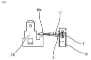
- Fig. 2 is a cross-sectional view showing the behavior of a brush and a pigtail in the fuel supply device according to the first embodiment of the present invention.
- pump casing assembly 1 is composed of pump casing body 2 and cover 3. Inside pump casing assembly 1, impeller 4 having blades 5 on its outer periphery is provided. This impeller 4 is rotatably supported within pump casing assembly 1 by central shaft 6 of rotor 8. In addition, central shaft 6 of impeller 4 is configured as the central shaft of rotor 8 of electric motor 7, and both ends thereof are rotatably supported by bearings 9 and 10.
- the cylindrical housing 11 also serves as a yoke for the electric motor 7, with a bracket 12, for example made of synthetic resin, fitted and connected to one end, and the pump casing assembly 1 fitted and connected to the other end.
- the housing 11 contains the rotor 8 inside, and has a permanent magnet 13 attached to its inner circumference, which acts as a stator.
- the bracket 12 is press-fitted into the housing 11 to regulate its own radial position, and the bearing 10 is press-fitted into the bracket 12. It also includes a check valve 14, a liquid outlet 15, etc., and the housing 11 and bracket 12 are fixed together as a single unit by curling the curled portion formed on the edge of the housing 11.
- the bracket 12 is also fitted with a power supply terminal 16 for supplying power from an external source, and is provided with a pigtail 17 fixed so as to be electrically conductive to the power supply terminal 16, and a brush 18 fixed integrally with the pigtail 17.
- This brush 18 is structured to abut against a commutator 19 located on the top of the rotor 8 housed inside the housing 11 while sliding.
- an externally applied voltage is passed from the power supply terminal 16 to the pigtail 17, from the pigtail 17 to the brush 18, and from the brush 18 to the commutator 19 to the rotor 8.
- the rotor 8 rotates. This rotation of the rotor 8 rotates the impeller 4, and liquid fuel is sucked in from the intake port 20.
- the liquid fuel pressurized by the rotational force of the impeller 4 passes through the inside of the fuel supply device and is fed to the internal combustion engine from the liquid outlet 15 provided in the bracket 12.
- the fixing portion 16a of the power supply terminal 16 which is provided to fix the power supply terminal 16 and the pigtail 17 so as to be electrically conductive, has a relative angle such that the axis G of the pigtail 17 fixed by the fixing portion 16a of the power supply terminal 16 is pulled out in a direction approximately perpendicular to the direction in which the brush 18 moves.
- the fixed portion 16a of the power supply terminal 16 is designed so that the axis G of the pigtail 17 is positioned at an angle where an extension of the axis G of the pigtail 17 intersects with approximately the center of the range S that indicates the up and down movement of the brush 18.
- the fixing portion 16a of the power supply terminal 16 can be fixed so that the power supply terminal 16 and the pigtail 17 can be electrically connected by, for example, fixing the fixing portion 16a of the power supply terminal 16 by crimping so as to bend the fixing portion 16a so as to sandwich the pigtail 17, or by welding the fixing portion 16a of the power supply terminal 16 and the pigtail 17 together.
- the pigtail 17 has no bent portion, making it possible to reduce the curvature. Also, by setting the relative angle at which the pigtail 17 follows up and down from approximately the center of the range S in which the brush 18 behaves up and down, the curvature that occurs when the pigtail 17 follows can be suppressed, making it possible to arrange the pigtail 17 in a routing structure that has a tolerance for metal fatigue.
- FIG. 3 is an enlarged side view of a main part showing the behavior of a brush and a pigtail in a fuel supply device according to a second embodiment of the present invention.
- the second embodiment of the present application has the same structure as the first embodiment of the present application shown in FIG. 2, but in order to position the axis G of the pigtail 17 at an angle where the extension of the axis G of the pigtail 17 intersects with approximately the center of the range S that indicates the up and down movement of the brush 18, the angle of the fixing portion 16a provided on the power supply terminal 16 may be changed to match the axis G of the pigtail 17.
- FIG. 4 is an enlarged cross-sectional view of the fixing portion 16a of the power supply terminal 16 in the first and second embodiments of the present invention.
- the fixing portion 16a of the power supply terminal 16 is fixed by crimping so as to sandwich the pigtail 17 in order to fix the power supply terminal 16 and the pigtail 17 so as to be conductive between them.
- a relief portion 16b is provided on the end surface of the fixing portion 16a provided on the power supply terminal 16 that sandwiches the pigtail 17 and is chamfered at an angle ⁇ .
- the angle ⁇ formed with the axis G of the pigtail 17 is set to an angle that satisfies the relationship ⁇ > ⁇ .
- the relief portion 16b formed by chamfering the end face of the fixed portion 16a of the power supply terminal 16 may be configured to have an R-shape.
- the angle formed by the tangent line drawn to the R-shape and the pigtail 17 when the brush is at its maximum movable position is defined as ⁇ , and the R-shape satisfies the relationship ⁇ > ⁇ .
- This application is suitable for realizing a fuel supply device that can suppress metal fatigue in the pigtail.
Landscapes
- Engineering & Computer Science (AREA)
- Chemical & Material Sciences (AREA)
- Combustion & Propulsion (AREA)
- Mechanical Engineering (AREA)
- General Engineering & Computer Science (AREA)
- Motor Or Generator Current Collectors (AREA)
Abstract
Description
以下、本願の実施の形態1を図1から図3に基づいて説明するが、各図において、同一、または相当部材、部位については同一符号を付して説明する。図1は本願の実施の形態1に係わる燃料供給装置を示す断面図である。図2は本願の実施の形態1に係わる燃料供給装置におけるブラシおよびピグテールの挙動を示す断面図である。
本願の実施の形態2を図3に基づいて説明するが、図において、同一、または相当部材、部位については同一符号を付して説明する。図3は本願の実施の形態2に係わる燃料供給装置におけるブラシおよびピグテールの挙動要部を示す要部拡大側面図である。
本願の実施の形態3を図4に基づいて説明する。図4は、本願の実施の形態1および実施の形態2における給電端子16の固定部16aの拡大断面図である。実施の形態1にて上述したとおり、給電端子16とピグテール17が導通可能なよう固定するためにピグテール17を挟み込む形で給電端子16の固定部16aをカシメにより固定する。給電端子16に設けた固定部16aのピグテール17を挟み込む端面に角度δの面取りで形成した逃がし部16bを設け、ブラシ18の上下挙動に追従することで、ピグテール17の軸線Gと形成される角度θを、δ>θの関係となる角度に設定する。
従って、例示されていない無数の変形例が、本願明細書に開示される技術の範囲内において想定される。例えば、少なくとも1つの構成要素を変形する場合、追加する場合または省略する場合、さらには、少なくとも1つの構成要素を抽出し、他の実施の形態の構成要素と組み合わせる場合が含まれるものとする。
Claims (5)
- インペラが内蔵されたポンプケーシング組立体と、一端側にブラケットが連結され、他端側に前記ポンプケーシング組立体が連結され、内部に回転子が収容されたハウジングと、前記ブラケットの内部に配置され、外部から給電される給電端子と、前記ブラケットの内部に配置され、前記給電端子に連結されるブラシとを備えた燃料供給装置であって、
一方側が前記給電端子の固定部に固定され、他方側が前記ブラシに固定されたピグテールを設け、前記ピグテールの軸線が前記ブラシの上下挙動の方向に対し垂直方向に位置し、前記ピグテールの軸線の延長線上が前記ブラシの上下挙動の範囲の中央部と交差することを特徴とする燃料供給装置。 - 前記給電端子の前記固定部と前記ピグテールは、カシメにより固定され、前記ブラシの上下挙動に追従する前記ピグテールの曲率を抑制することを特徴とした請求項1に記載の燃料供給装置。
- 前記給電端子の前記固定部と前記ピグテールは、溶接により固定され、前記ブラシの上下挙動に追従する前記ピグテールの曲率を抑制することを特徴とする請求項1に記載の燃料供給装置。
- 前記給電端子の前記固定部の端面に面取り形状で形成された逃がし部を設け、面取り形状の角度δが、前記ブラシの最大挙動時に前記ピグテールが形成する屈曲角度θよりも大きいδ>θの関係となる角度とすることを特徴とする請求項1から請求項3のいずれか1項に記載の燃料供給装置。
- 前記給電端子の前記固定部の端面にR形状で形成された逃がし部を設け、前記ブラシの最大挙動時の前記ピグテールと並行にR形状に引いた接線の角度δが、前記ブラシの最大挙動時に前記ピグテールが形成する屈曲角度θよりも大きいδ>θの関係となる角度とすることを特徴とする請求項1から請求項3のいずれか1項に記載の燃料供給装置。
Priority Applications (2)
| Application Number | Priority Date | Filing Date | Title |
|---|---|---|---|
| PCT/JP2023/012132 WO2024201641A1 (ja) | 2023-03-27 | 2023-03-27 | 燃料供給装置 |
| JP2025509272A JPWO2024201641A1 (ja) | 2023-03-27 | 2023-03-27 |
Applications Claiming Priority (1)
| Application Number | Priority Date | Filing Date | Title |
|---|---|---|---|
| PCT/JP2023/012132 WO2024201641A1 (ja) | 2023-03-27 | 2023-03-27 | 燃料供給装置 |
Publications (1)
| Publication Number | Publication Date |
|---|---|
| WO2024201641A1 true WO2024201641A1 (ja) | 2024-10-03 |
Family
ID=92904010
Family Applications (1)
| Application Number | Title | Priority Date | Filing Date |
|---|---|---|---|
| PCT/JP2023/012132 Ceased WO2024201641A1 (ja) | 2023-03-27 | 2023-03-27 | 燃料供給装置 |
Country Status (2)
| Country | Link |
|---|---|
| JP (1) | JPWO2024201641A1 (ja) |
| WO (1) | WO2024201641A1 (ja) |
Citations (4)
| Publication number | Priority date | Publication date | Assignee | Title |
|---|---|---|---|---|
| JPS5579678U (ja) * | 1978-11-28 | 1980-06-02 | ||
| JP2004011527A (ja) * | 2002-06-06 | 2004-01-15 | Hitachi Unisia Automotive Ltd | 燃料ポンプ |
| JP2017077052A (ja) * | 2015-10-13 | 2017-04-20 | 株式会社ミツバ | ブラシ装置及び燃料ポンプ |
| JP2017120038A (ja) * | 2015-12-28 | 2017-07-06 | 株式会社ケーヒン | 燃料ポンプ |
-
2023
- 2023-03-27 JP JP2025509272A patent/JPWO2024201641A1/ja active Pending
- 2023-03-27 WO PCT/JP2023/012132 patent/WO2024201641A1/ja not_active Ceased
Patent Citations (4)
| Publication number | Priority date | Publication date | Assignee | Title |
|---|---|---|---|---|
| JPS5579678U (ja) * | 1978-11-28 | 1980-06-02 | ||
| JP2004011527A (ja) * | 2002-06-06 | 2004-01-15 | Hitachi Unisia Automotive Ltd | 燃料ポンプ |
| JP2017077052A (ja) * | 2015-10-13 | 2017-04-20 | 株式会社ミツバ | ブラシ装置及び燃料ポンプ |
| JP2017120038A (ja) * | 2015-12-28 | 2017-07-06 | 株式会社ケーヒン | 燃料ポンプ |
Also Published As
| Publication number | Publication date |
|---|---|
| JPWO2024201641A1 (ja) | 2024-10-03 |
Similar Documents
| Publication | Publication Date | Title |
|---|---|---|
| JP7464089B2 (ja) | 電動オイルポンプ | |
| US8096857B2 (en) | Power tool, in particular angle grinder | |
| US12587060B2 (en) | Electric motor for a motor vehicle | |
| JP2001157405A (ja) | スラストキャップ | |
| JP2015166570A (ja) | 電動オイルポンプ | |
| CN117097071A (zh) | 共用bldc电机的车辆电动座椅用执行器 | |
| JP5135873B2 (ja) | 電動モータおよび燃料ポンプ | |
| JP2008005689A (ja) | 燃料ポンプ | |
| JP2008064030A (ja) | 燃料ポンプ | |
| JP2012031807A (ja) | 燃料ポンプ | |
| US10047745B2 (en) | Electric oil pump | |
| JP2008199740A (ja) | 燃料ポンプおよびその製造方法 | |
| JP2012065535A (ja) | 燃料ポンプ | |
| JP2005207320A (ja) | 燃料ポンプ | |
| JP3941108B2 (ja) | 燃料ポンプおよびその製造方法 | |
| JP2008215121A (ja) | 燃料ポンプ | |
| WO2019208073A1 (ja) | モータユニット及び電動オイルポンプ | |
| JP2014152726A (ja) | 燃料ポンプモジュール | |
| JP2009225625A (ja) | ブラシ付き電動モータ | |
| US20080069710A1 (en) | Electric motor and fuel pump having the same | |
| CN210859000U (zh) | 一种泵体组立与电机一体式的燃油泵 | |
| JP7463811B2 (ja) | 電動ポンプ | |
| KR0169028B1 (ko) | 회전체의 부착 구조 및 이를 이용한 전동 송풍기 | |
| JP7221121B2 (ja) | 燃料供給装置 | |
| JP4935187B2 (ja) | 電動モータおよび燃料ポンプ |
Legal Events
| Date | Code | Title | Description |
|---|---|---|---|
| 121 | Ep: the epo has been informed by wipo that ep was designated in this application |
Ref document number: 23930281 Country of ref document: EP Kind code of ref document: A1 |
|
| WWE | Wipo information: entry into national phase |
Ref document number: 2025509272 Country of ref document: JP |
|
| WWE | Wipo information: entry into national phase |
Ref document number: 2501004685 Country of ref document: TH |
|
| NENP | Non-entry into the national phase |
Ref country code: DE |
|
| 122 | Ep: pct application non-entry in european phase |
Ref document number: 23930281 Country of ref document: EP Kind code of ref document: A1 |