WO2024195543A1 - 音響装置、信号処理方法、表示方法 - Google Patents
音響装置、信号処理方法、表示方法 Download PDFInfo
- Publication number
- WO2024195543A1 WO2024195543A1 PCT/JP2024/008526 JP2024008526W WO2024195543A1 WO 2024195543 A1 WO2024195543 A1 WO 2024195543A1 JP 2024008526 W JP2024008526 W JP 2024008526W WO 2024195543 A1 WO2024195543 A1 WO 2024195543A1
- Authority
- WO
- WIPO (PCT)
- Prior art keywords
- coil
- sensing
- diaphragm
- signal
- driving
- Prior art date
- Legal status (The legal status is an assumption and is not a legal conclusion. Google has not performed a legal analysis and makes no representation as to the accuracy of the status listed.)
- Ceased
Links
Images






Classifications
-
- H—ELECTRICITY
- H04—ELECTRIC COMMUNICATION TECHNIQUE
- H04R—LOUDSPEAKERS, MICROPHONES, GRAMOPHONE PICK-UPS OR LIKE ACOUSTIC ELECTROMECHANICAL TRANSDUCERS; ELECTRIC HEARING AIDS; PUBLIC ADDRESS SYSTEMS
- H04R9/00—Transducers of moving-coil, moving-strip, or moving-wire type
- H04R9/06—Loudspeakers
-
- H—ELECTRICITY
- H04—ELECTRIC COMMUNICATION TECHNIQUE
- H04R—LOUDSPEAKERS, MICROPHONES, GRAMOPHONE PICK-UPS OR LIKE ACOUSTIC ELECTROMECHANICAL TRANSDUCERS; ELECTRIC HEARING AIDS; PUBLIC ADDRESS SYSTEMS
- H04R9/00—Transducers of moving-coil, moving-strip, or moving-wire type
- H04R9/02—Details
- H04R9/025—Magnetic circuit
-
- H—ELECTRICITY
- H04—ELECTRIC COMMUNICATION TECHNIQUE
- H04R—LOUDSPEAKERS, MICROPHONES, GRAMOPHONE PICK-UPS OR LIKE ACOUSTIC ELECTROMECHANICAL TRANSDUCERS; ELECTRIC HEARING AIDS; PUBLIC ADDRESS SYSTEMS
- H04R9/00—Transducers of moving-coil, moving-strip, or moving-wire type
- H04R9/02—Details
- H04R9/04—Construction, mounting, or centering of coil
- H04R9/046—Construction
-
- H—ELECTRICITY
- H04—ELECTRIC COMMUNICATION TECHNIQUE
- H04R—LOUDSPEAKERS, MICROPHONES, GRAMOPHONE PICK-UPS OR LIKE ACOUSTIC ELECTROMECHANICAL TRANSDUCERS; ELECTRIC HEARING AIDS; PUBLIC ADDRESS SYSTEMS
- H04R2209/00—Details of transducers of the moving-coil, moving-strip, or moving-wire type covered by H04R9/00 but not provided for in any of its subgroups
- H04R2209/041—Voice coil arrangements comprising more than one voice coil unit on the same bobbin
-
- H—ELECTRICITY
- H04—ELECTRIC COMMUNICATION TECHNIQUE
- H04R—LOUDSPEAKERS, MICROPHONES, GRAMOPHONE PICK-UPS OR LIKE ACOUSTIC ELECTROMECHANICAL TRANSDUCERS; ELECTRIC HEARING AIDS; PUBLIC ADDRESS SYSTEMS
- H04R3/00—Circuits for transducers
- H04R3/002—Damping circuit arrangements for transducers, e.g. motional feedback circuits
Definitions
- This technology relates to audio devices such as speakers and microphones, signal processing methods in audio devices, and display methods for displaying information related to audio devices.
- a type of audio device known in the art is one that has a moving part with a coil connected to a diaphragm, such as a dynamic speaker or microphone, and a magnetic circuit part that has a magnet and a yoke and generates a magnetic force that acts on the coil.
- a moving coil type audio device
- MFB Motional Feed-Back
- a sensing coil for detecting the movement of the diaphragm is provided in addition to a driving coil for driving the diaphragm in a moving part connected to the diaphragm, and signal processing for distortion correction is performed on the acoustic signal based on the electrical signal of the sensing coil.
- Patent Document 1 when providing a sensing coil separately from a driving coil, the sensing coil is wound on a bobbin separate from the bobbin of the driving coil, and a dedicated magnet and yoke (including a plate) are provided to form a magnetic circuit for the sensing coil. In other words, a set of a magnet and a yoke is provided for each of the driving coil and the sensing coil.
- Patent Document 2 when a sensing coil is provided separately from a driving coil, a set of a magnet and a yoke is provided for each of the driving coil and the sensing coil.
- This technology was developed in consideration of the above circumstances, and aims to prevent the moving coil type audio device from becoming larger and heavier when multiple coils are provided in the moving part.
- a first acoustic device comprises a diaphragm, a movable part having a coil and connected to the diaphragm, and a magnetic circuit part having a magnet and a yoke and generating a magnetic force acting on the coil, wherein the magnetic circuit part has a top plate part as part of the yoke, the top plate part having an upper surface part located on the magnet and extending in a direction approximately perpendicular to the movable direction of the movable part, the top plate part having a protrusion part protruding downward from an inner edge part or an outer edge part of the upper surface part, the movable part has a first coil and a second coil as the coil, and the wound portions of the first coil and the second coil in the movable part face a protruding side surface which is the side surface on which the protrusion part is formed in the top plate part.
- a second acoustic device relating to the present technology includes a diaphragm, a movable part connected to the diaphragm having a driving coil for driving the diaphragm and a sensing coil for detecting movement of the diaphragm, a magnetic circuit part having a magnet and a yoke and generating a magnetic force acting on the driving coil and a magnetic force acting on the sensing coil, and an electric circuit part generating a drive signal for the driving coil based on a sensing signal from the sensing coil, wherein the electric circuit part includes a feedback control part having a feedback loop that processes an acoustic signal based on the sensing signal, and a feedforward control part that performs arithmetic processing using a predetermined coefficient on the acoustic signal input to the feedback loop.
- the device includes a feedforward control unit in addition to a feedback control unit that performs feedback control based on the sensing signal of the sensing coil, as in conventional MFB control
- the signal processing method related to the present technology is a signal processing method in an acoustic device including a diaphragm, a movable part connected to the diaphragm having a driving coil for driving the diaphragm and a sensing coil for detecting movement of the diaphragm, a magnetic circuit part having a magnet and a yoke and generating a magnetic force acting on the driving coil and a magnetic force acting on the sensing coil, and an electric circuit part generating a drive signal for the driving coil based on a sensing signal from the sensing coil, in which the electric circuit part performs feedback control for processing an acoustic signal using a feedback loop to which the sensing signal is input, and feedforward control for performing arithmetic processing using a predetermined coefficient on the acoustic signal input to the feedback loop.
- a display method relating to the present technology is a display method for displaying information indicating the vibration transmission characteristics of an acoustic device measured based on a detection signal of the sensing coil in an acoustic device comprising: a diaphragm; a movable part having a coil and connected to the diaphragm; and a magnetic circuit part having a magnet and a yoke and generating a magnetic force acting on the coil, wherein the magnetic circuit part has a top plate part as part of the yoke, the top plate part having an upper surface part located on the magnet and extending in a direction approximately perpendicular to the movable direction of the movable part, and the top plate part has a protrusion part that protrudes downward from an inner edge part or an outer edge part of the upper surface part, the movable part has, as the coil, a driving coil for driving the diaphragm and a sensing coil for detecting the movement of the diaphragm, and the wound portions of
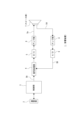
- FIG. 1 is a block diagram showing an example configuration of an audio device according to a first embodiment of the present technology.
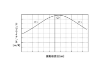
- 11 is a diagram showing an example of compliance characteristics of a diaphragm.
- FIG. 13 is a diagram showing an example of waveform distortion.
- 1 is a schematic vertical cross-sectional view of a speaker unit included in an acoustic device according to an embodiment.
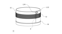
- 2 is a schematic external perspective view of a movable part of the speaker unit.
- FIG. 4 is a diagram showing a schematic longitudinal sectional structure of a wound portion of a driving coil and a sensing coil in a movable part.
- FIG. FIG. 4 is an explanatory diagram of a configuration example of an internal magnet type magnetic circuit portion.
- FIG. 2 is an explanatory diagram of a configuration example of an internal/external magnet type magnetic circuit section.
- 5 is an explanatory diagram of a magnetic flux density distribution for a sensing coil.
- FIG. FIG. 13 is a diagram showing a simulation result of a magnetic flux density distribution when the configuration of Patent Document 1 is adopted.
- 11A and 11B are diagrams showing simulation results of magnetic flux density distribution in an acoustic device according to an embodiment.
- 11A to 11C are diagrams showing examples of variations in the shape of a protrusion.
- FIG. 2 is an explanatory diagram of a bobbinless structure.
- FIG. 1 is a block diagram illustrating an example of a configuration for implementing a distortion correction method according to an embodiment.
- FIG. 15 is a diagram showing a transfer function model of the configuration shown in FIG. 14 .
- 13 is a diagram showing an example of the configuration of an electric circuit section that performs processing taking into account the induction characteristics from the driving coil to the sensing coil.
- FIG. 1 is a diagram showing an example of the configuration of an acoustic device for compensating for changes over time and individual variations in vibration transmission characteristics.
- FIG. 11 is a diagram for explaining an example of the configuration of a sound reproducing system according to a second embodiment.
- FIG. 11 is a diagram showing an example of a GUI in the second embodiment.
- FIG. 1 is a block diagram showing an example of the configuration of an audio device 1 according to a first embodiment of the present technology.
- the audio device 1 is configured as a "moving coil type" audio device.
- a moving coil type audio device refers to an audio device that includes a diaphragm, a movable part having a coil and connected to the diaphragm, and a magnetic circuit part having a magnet and a yoke and generating a magnetic force acting on the coil.
- an audio device configured as a speaker device such as an earphone or a headphone is exemplified as such a moving coil type audio device 1.
- the audio device 1 includes a communication unit 2, a control unit 3, a signal processing unit 4, a D/A (Digital to Analog) converter 5, an amplifier unit 6, a speaker unit 7, an amplifier unit 8, and an A/D (Analog to Digital) converter 9.
- a communication unit 2 a control unit 3
- a signal processing unit 4 a D/A (Digital to Analog) converter 5
- an amplifier unit 6 a speaker unit 7, an amplifier unit 8, and an A/D (Analog to Digital) converter 9.
- A/D Analog to Digital
- the control unit 3 is configured with a microcomputer having, for example, a CPU (Central Processing Unit), a ROM (Read Only Memory), and a RAM (Random Access Memory), and the CPU executes processing based on a program stored in the ROM, thereby performing overall control of the audio device 1 and various types of calculation processing.
- the control unit 3 receives a digital acoustic signal SA from an external device via the communication unit 2, and outputs the signal to a downstream signal processing unit 4.
- the communication unit 2 performs wired or wireless communication between the external device and the control unit 3, such as inter-device communication and communication via a network, such as the Internet.
- the audio signal SA received from the external device is an audio signal of multiple channels, such as a stereo audio signal.
- a configuration for one channel is shown as a representative audio signal reproduction system including a speaker unit 7, but in reality, the reproduction system is provided for multiple channels.
- two speaker units 7 are provided corresponding to the L (left) channel and the R (right) channel, and in a configuration compatible with multi-channel reproduction of three or more channels, three or more speaker units 7 are provided.
- the audio device 1 may be configured to have only one speaker unit 7 so as to support monaural audio reproduction.
- the signal processing unit 4 is configured as a signal processing device such as a DSP (Digital Signal Processor), and performs various signal processing on the audio signal SA. For example, it performs equalization processing to adjust the frequency characteristics of the audio signal SA.
- the signal processing unit 4 in this embodiment performs signal processing for distortion correction on the audio signal SA based on a sensing signal (sensing signal regarding the movement of the diaphragm) obtained by a sensing coil 14 (described later) in the speaker unit 7. This corresponds to the above-mentioned MFB (Motional Feed-Back) control.
- MFB Motion Feed-Back
- the distortion of interest is caused by the mechanical properties of the diaphragm.
- distortion caused by loss of front-to-back symmetry in the vibration of the diaphragm
- distortion caused by the Doppler effect in the reproduction of high frequencies when reproducing a wide-band signal from low to high frequencies are various types of distortion, such as distortion caused by loss of front-to-back symmetry in the vibration of the diaphragm, and distortion caused by the Doppler effect in the reproduction of high frequencies when reproducing a wide-band signal from low to high frequencies.
- the acoustic signal SA that has been subjected to signal processing by the signal processing unit 4 is converted into an analog signal by the D/A converter 5 and then amplified by the amplifier unit 6, and the amplified signal is supplied to the speaker unit 7 as the acoustic signal Sa.
- the speaker unit 7 is provided with a drive coil 13 for driving a diaphragm (diaphragm 10).
- an acoustic signal Sa is input as a drive signal for the drive coil 13, and the drive coil 13 is driven based on the acoustic signal Sa, causing the diaphragm 10 to vibrate in response to the acoustic signal Sa, thereby realizing sound reproduction in response to the acoustic signal Sa.
- This can be expressed as converting the acoustic signal Sa as an electrical signal into sound (air vibration).
- the speaker unit 7 has a sensing coil 14 on a movable part connected to the diaphragm 10.
- This sensing coil 14 provides a sensing signal Sd regarding the movement of the diaphragm 10.
- the sensing signal Sd is amplified by the amplifier section 8, then converted into a digital sensing signal SD by the A/D converter 9 and input to the signal processing section 4.
- a signal indicating the movement of the diaphragm 10 is fed back to the signal processing section 4.
- FIG. 4 is a schematic vertical cross-sectional view of the speaker unit 7, and FIG. 5 is a schematic perspective view of the exterior of a movable portion 11 provided in the speaker unit 7. As shown in FIG. In FIG. 4, only the components of the speaker unit 7 that are particularly related to the embodiment are shown.
- the speaker unit 7 includes a diaphragm 10, a movable part 11 having a coil and connected to the diaphragm 10, and a magnetic circuit part 15 having a magnet 16 and a yoke 17 and generating a magnetic force acting on the coil (see FIG. 4).
- the vertical dotted line indicated by "X" represents the central axis of the speaker unit 7.
- the speaker unit 7 of this embodiment employs, as the magnetic circuit unit 15, an external magnet type magnetic circuit unit in which a magnet 16 is positioned on the outer periphery side of the coil of the movable unit 11.
- the direction in which the movable part 11 moves is the vertical direction (up-down direction), and the direction in which the diaphragm 10 is located as viewed from the coil in the movable part 11 is the upward direction.
- the diaphragm 10 has a substantially circular outer shape when viewed from above, and its outer periphery is supported by a non-magnetic support portion 20.
- the diaphragm 10 is connected to the movable portion 11 at a portion on the inner periphery side of the portion supported by the support portion 20.
- the movable part 11 is formed by winding a driving coil 13 and a sensing coil 14 around the outer circumferential surface of a substantially cylindrical bobbin 12 (see Figures 4 and 5).
- the driving coil 13 and the sensing coil 14 are wound at a distance in the vertical direction. As shown in the figure, in this example, the driving coil 13 is wound above the sensing coil 14.
- the winding directions of the driving coil 13 and the sensing coil 14 are opposite to each other, but this will be explained later.
- lead wires L13 from the winding start end and winding end end of the driving coil 13 and lead wires L14 from the winding start end and winding end end of the sensing coil 14 are wired in the vertical direction on the outer circumferential surface of the bobbin 12 (see FIG. 5).
- the lead wires L13 and L14 are wired in the upward direction from the respective coils.
- the lead wire L13 is connected to the amplifier section 6 shown in FIG. 1, which makes it possible to drive the driving coil 13 using the acoustic signal Sa as a driving signal as described above.
- the lead line L14 is connected to the amplifier section 8 shown in FIG. 1, which makes it possible to feed back the sensing signal SD to the signal processing section 4 as described above.
- the portion where the lead wire L14 is present on the inside as described above is a portion that is more convex toward the outer periphery than the other portions.
- this portion will be referred to as the "outer convex portion O.”
- the thickness of the conductors used in the sensing coil 14, including the conductors of the lead wire L14 is made thinner than the thickness of the conductors (including the conductors of the lead wire L13) used in the drive coil 13.
- the wire diameter of the latter conductor is made smaller than the wire diameter of the former conductor.
- the conductors of the driving coil 13 and the sensing coil 14 are made of a conductor called a voice coil wire.
- a voice coil wire For example, copper wire or copper-clad aluminum wire is used.
- the conductor of the driving coil 13 it is desirable for the conductor of the driving coil 13 to have a large wire diameter so that a large current can flow to drive the diaphragm 10.
- the conductor of the sensing coil 14 does not need to pass a current because an induced electromotive force is generated in response to the movement of the diaphragm 10 and its voltage value is detected. Also, the more turns there are, the larger the induced electromotive force is and the higher the sensitivity of vibration sensing is, so a conductor with a high conductor resistance (i.e. a small wire diameter) can be used.
- FIG. 6 is a schematic diagram showing a vertical cross-sectional structure of the wound portion of the movable portion 11 around which the driving coil 13 and the sensing coil 14 are wound. 6, for example, the driving coil 13 may be wound in two layers, and the sensing coil 14 may be wound in four layers. Note that the number of layers is not limited to this example.
- the upper end of the bobbin 12 of the movable part 11 is connected to the diaphragm 10. This causes the diaphragm 10 to vibrate as the movable part 11 moves up and down.
- the yoke 17 has a top plate section 18 located above the magnet 16 and having an upper surface section 18a extending in a direction (horizontal direction) that is approximately perpendicular to the moving direction (vertical direction) of the movable section 11, and a pole piece section 19d located below the magnet 16 and having a bottom section 19a that holds the magnet 16 together with the above-mentioned upper surface section 18a.
- the top plate portion 18 has an annular shape when viewed from above, and has a protruding portion 18b that protrudes downward from the inner edge of the upper surface portion 18a.
- the protruding portion 18b has an annular shape when viewed from below.
- the magnet 16 is positioned on the outer periphery side of the protruding portion 18b, and is sandwiched between the top surface portion 18a and the bottom portion 19a.
- the side surface of the top plate portion 18 on which the protruding portion 18b is formed (in this example, the inner side surface) will be referred to as the "protruding side surface Su.”
- the pole piece portion 19 has an annular shape when viewed from below, and has a wall portion 19b that protrudes upward from the inner edge of the bottom portion 19a.
- the wall portion 19b has an annular shape when viewed from above.
- the wall portion 19b is located on the inside of the protruding portion 18b of the top plate portion 18.
- the surface of the wall portion 19b facing the protruding portion 18b is defined as an opposing surface Si.
- a gap G is provided as an air gap between the opposing surface Si and the protruding side surface Su of the top plate portion 18.
- the cross-sectional width of the protruding portion 18b of the top plate portion 18 is narrower than the cross-sectional width of the wall portion 19b (the horizontal length in cross section).
- the movable part 11 is disposed so that the winding portions of the driving coil 13 and the sensing coil 14 are located within the gap G.
- the winding portions of the driving coil 13 and the sensing coil 14 in the movable part 11 face the protruding side surface Su of the top plate part 18.
- the driving coil 13 and the sensing coil 14 face the protruding side surface Su located on the outside, as shown in the figure.
- the movable part 11 is shown in a neutral position, and in this neutral state, as shown in the figure, in this example, the vertical position of the driving coil 13 is near the top surface part 18a, and the vertical position of the sensing coil 14 is near the tip (lower end) of the protruding part 18b.
- the winding portions of the driving coil 13 and the sensing coil 14 in the movable part 11 are positioned within the gap G, so that the magnetic force generated by the magnetic circuit part 15 in the vicinity of the gap G can be applied to the driving coil 13 and the sensing coil 14, respectively. Therefore, by supplying a driving signal (passing a driving current) to the driving coil 13, the movable part 11 can be displaced in the vertical direction, and the diaphragm 10 can be vibrated. Furthermore, when the movable part 11 is displaced, an electrical signal corresponding to the amount and direction of displacement can be generated in the sensing coil 14, and a sensing signal Sd indicating the movement of the diaphragm 10 can be obtained.
- an external magnet type magnetic circuit section 15 is used as the magnetic circuit section that generates a magnetic force acting on the coil.
- the speaker section 7 of the embodiment can also use an internal magnet type magnetic circuit section 15A as exemplified in FIG. 7, or an internal/external magnet type magnetic circuit section 15B as exemplified in FIG. 8. Since the configurations of the magnetic circuit portions 15A and 15B are symmetrical with respect to the central axis X, only the configuration on the right side of the central axis X is extracted and shown in FIGS.
- a yoke 17A is provided in which the positional relationship in the inside-outside direction between the magnet 16, the protruding portion 18b, and the wall portion 19b is reversed from that in Fig. 4.
- this yoke 17A has a top plate portion 18A and a pole piece portion 19A, and as shown in the figure, the top plate portion 18A has an upper surface portion 18a having a substantially circular shape in a top view, and a protruding portion 18b protruding downward from the outer edge of the upper surface portion 18a.
- the protruding side surface Su which is the side surface of the top plate portion 18A on which the protruding portion 18b is formed, faces outward.
- the pole piece portion 19A has a bottom portion 19a having a substantially circular shape when viewed from below, and a wall portion 19b protruding upward from the outer edge of the bottom portion 19a.
- the magnet 16 in this case is located inside the protruding portion 18b, and is sandwiched between the bottom portion 19a and the upper surface portion 18a of the top plate portion 18A.
- the opposing surface Si of the wall portion 19b in the pole piece portion 19A faces inward, and the windings of the driving coil 13 and the sensing coil 14 in the movable portion 11 are located in the gap G formed between this opposing surface Si and the protruding side surface Su of the top plate portion 18A. In other words, the windings face the protruding side surface Su.
- a yoke 17B is provided that has a top plate portion 18A having a protrusion 18b protruding downward from the outer edge of the top surface portion 18a, a top plate portion 18 positioned outer than the top plate portion 18A and having a protrusion 18b protruding downward from the inner edge of the top surface portion 18a, and a pole piece portion 19B having a disk-shaped bottom portion 19a positioned below the top plate portion 18A and the top plate portion 18.
- two magnets 16 are provided: a magnet 16 (approximately disk-shaped) positioned inside the protrusion 18b of the top plate portion 18A, and a magnet 16 (annular) positioned outside the protrusion 18b of the top plate portion 18.
- the bottom 19a of the pole piece portion 19B extends horizontally (radially) from the central axis X to near the outer edge of the magnet 16 arranged on the outside, and the inner magnet 16 is sandwiched between the bottom 19a and the upper surface 18a of the top plate portion 18A, and the outer magnet 16 is sandwiched between the bottom 19a and the upper surface 18a of the top plate portion 18.
- the magnetic circuit section can also be a sigma-type magnetic circuit section in which two magnets are sandwiched alternately (with opposite polarities) between three plates, and is not limited to the external magnet type, internal magnet type, and internal/external magnet type magnetic circuit sections exemplified above.
- a protrusion 18b is formed on the top plate section 18 (or 18A), and the wound portions of the driving coil 13 and the sensing coil 14 in the movable section 11 face the protruding side surface Su of the top plate section 18.
- the sensing coil 14 it is desirable to increase the magnetic flux density of the magnetic force acting on the driving coil 13 in order to improve the driving efficiency.
- the sensing coil 14 it is ideal for the sensing coil 14 to have a uniform magnetic flux density distribution in the vertical direction in order to accurately detect the amount of displacement of the movable part 11.
- FIG. 9A and 9B are schematic diagrams showing the case where the magnetic flux density distribution in the vertical direction is constant (FIG. 9A) and the case where it is not constant (FIG. 9B).
- FIG. 9B the amount of change in the magnetic force received when the sensing coil 14 moves a certain amount changes depending on the vertical position of the sensing coil 14.
- the amount of change in the value of the sensing signal when the sensing coil 14 moves a certain amount changes depending on the vertical position of the sensing coil 14.
- FIG. 10 shows the results of a simulation of the magnetic flux density distribution when the configuration of Patent Document 1 is adopted.
- a first magnetic circuit formed by a first magnet and a first yoke (including a top plate) shown in FIG. 10A is configured to obtain a magnetic flux density distribution for a driving coil as shown by "md” in FIG. 10B.
- a second magnetic circuit formed by a second magnet and a second yoke shown in FIG. 10A is configured to obtain a magnetic flux density distribution for a sensing coil as shown by "ms" in FIG. 10B.
- FIG. 10 shows the results of a simulation of the magnetic flux density distribution when the configuration of Patent Document 1 is adopted.
- a first magnetic circuit formed by a first magnet and a first yoke (including a top plate) shown in FIG. 10A is configured to obtain a magnetic flux density distribution for a driving coil as shown by "md" in FIG. 10B.
- the Z position (vertical position) shown on the vertical axis represents the vertical center position of the driving coil and the sensing coil when they are in the neutral position as "0".
- the r-direction magnetic flux density on the horizontal axis means the density of the magnetic flux in the vertical direction in the horizontal (radial) direction.
- the r-direction magnetic flux density distribution ms of the sensing coil is designed to have a characteristic of approximately constant magnetic flux density regardless of vertical position (i.e., approximately flat characteristic).
- the peak value of the r-direction magnetic flux density distribution md is made larger than the maximum value of the r-direction magnetic flux density distribution ms.
- a protrusion 18b is provided on the top plate portion 18 (or 18A), making it possible to provide a magnetic flux density distribution suitable for the application of the coil in the arrangement area of each coil without providing a magnet and a yoke for each coil.
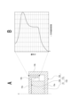
- Fig. 11 shows the simulation results of the magnetic flux density distribution when the internal magnet type magnetic circuit unit 15A shown in Fig. 7 is adopted.
- Fig. 11B shows the distribution characteristics of the r-direction magnetic flux density in the vertical range corresponding to the winding portion of the driving coil 13 and the sensing coil 14, indicated by the vertical double arrows in Fig. 11A.
- a peak of the r-direction magnetic flux density is obtained near the winding portion of the driving coil 13 as shown in the figure, and the distribution of the r-direction magnetic flux density is flat near the winding portion of the sensing coil 14.
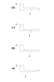
- Fig. 12 shows examples of variations in the shape of the protrusion 18b. Note that Fig. 12 is based on the assumption that the magnetic circuit unit 15 is an external magnet type, but similar shape variations can also be adopted for the magnetic circuit unit 15A of the internal magnet type.
- FIG. 12A shows an example of a tapered shape, in which the width of the protruding portion 18b narrows toward the bottom as shown in the figure.
- Figures 12B and 12C are examples of providing a cutout, with Figure 12B being an example in which a notch that convexly extends outward is provided in a part of protrusion 18b, and Figure 12C being an example in which a notch that convexly extends outward is provided from the upper end of protrusion 18b to the lower end of upper surface portion 18a.
- 12D shows an example in which the inner peripheral surface of the protruding portion 18b is offset laterally (radially) from the inner peripheral surface of the upper surface portion 18a, specifically, the inner peripheral surface of the protruding portion 18b is offset toward the outer periphery from the inner peripheral surface of the upper surface portion 18a. Also, in this example, the lower end of the protruding portion 18b is bent toward the inner periphery.
- the driving coil 13 and the sensing coil 14 are wound around the same bobbin 12, which means that the supporting bodies for the driving coil 13 and the sensing coil 14 are the same, thereby preventing any difference in movement between the driving coil 13 and the sensing coil 14. Therefore, the accuracy with which the sensing coil 14 detects the movement of the diaphragm 10 can be improved.
- the driving coil 13 and the sensing coil 14 are wound at a distance in the vertical direction, which reduces the electromotive force generated in the sensing coil 14 when a driving current flows through the driving coil 13. Therefore, the accuracy of detection of the movement of the diaphragm 10 by the sensing coil can be improved. Furthermore, by separating the driving coil 13 and the sensing coil 14, it is possible to prevent the driving coil 13 from overlapping an area in the magnetic circuit section 15 (or 15A, 15B) that has magnetic flux density distribution characteristics for sensing, or conversely, to prevent the sensing coil 14 from overlapping an area that has magnetic flux density distribution characteristics for driving. Therefore, it is possible to improve both the driving efficiency and driving performance of the diaphragm 10 and the detection accuracy of the movement of the diaphragm 10 .
- the winding directions of the driving coil 13 and the sensing coil 14 are opposite to each other.
- the electromotive force generated in the sensing coil 14 when the movable part 11 moves and the electromotive force generated in the sensing coil 14 when a driving current flows through the driving coil 13 can be made to have opposite polarity. Therefore, it is possible to reduce the voltage change width of the sensing signal from the sensing coil 14 when the movable part 11 moves.
- the driving coil 13 is wound around the outside of the lead-out wire L14 of the sensing coil 14, and the wire thickness of the sensing coil 14 including the lead-out wire L14 is made thinner than the wire thickness of the driving coil 13. This makes it possible to reduce the amount of protrusion of the outer convex portion O of the driving coil 13 . Therefore, the amount of clearance that must be secured between the drive coil 13 and the yoke can be reduced, and the magnetic gap of the drive coil 13 can be made smaller, thereby improving the drive efficiency of the diaphragm 10 .
- the driving coil 13 and the sensing coil 14 may be integrally wound by a bobbinless winding method.
- a bobbinless voice coil may be used using a self-bonding wire, in which case the driving coil 13 may have a two-layer structure as shown in Fig. 13A or a four-layer structure as shown in Fig. 13B.
- the reason why the number of layers is an even number is to align the positions of the start and end of the coil winding.
- the number of layers may be either an even number or an odd number. In the example of Fig.
- the driving coil 13 has four layers only in a portion of the vertical direction and two layers in the remaining region, and the four layers of the sensing coil 14 are wound around the outer periphery of the two-layer winding region of the driving coil 13 separated from the four-layer region in the vertical direction.
- the number of layers in some vertical regions may be different from that in other regions. In this case, the number of layers in some vertical regions may be odd and the number of layers in other regions may be even, or vice versa.
- the bobbin 12 is no longer necessary, making the device smaller and lighter.
- the driving coil 13 and the sensing coil 14 can be said to be supported by the same support body, just as in the case where the driving coil 13 and the sensing coil 14 are wound around the same bobbin 12.
- FIG. 14 is a block diagram for explaining an example configuration for implementing the distortion correction method according to the embodiment, and shows an example internal configuration of the signal processing unit 4, as well as the D/A converter 5, amplifier unit 6, speaker unit 7 (driving coil 13 and sensing coil 14), amplifier unit 8, and A/D converter 9 shown in FIG. 1.
- the signal processing unit 4 includes an equalizer 21, a first FF (Feed-Forward) filter 22, a second FF filter 23, an adder 24, an FB (Feed-Back) filter 25, and an adder 26.
- the equalizer 21, the first FF filter 22, the second FF filter 23, and the FB filter 25 are configured as frequency filters that adjust the frequency characteristics of the input signal, and digital filters such as an FIR (Finite Impulse Response) filter or an IIR (Infinite Impulse Response) filter are used.
- the equalizer 21 applies filtering to the input audio signal SA to adjust the sound quality.
- the first FF filter 22, the second FF filter 23, and the adder 24 constitute the feedforward control unit 28.
- the first FF filter 22 and the second FF filter 23 perform filtering to correct linear characteristics and filtering to correct non-linear characteristics, respectively, in feedforward control.
- the audio signal SA processed by the equalizer 21 is filtered by the first FF filter 22 and the second FF filter 23, respectively, and these filtered signals are added in the adder 24.
- the FB filter 25 and the adder 26 constitute a feedback control unit 27.
- the FB filter 25 receives the sensing signal SD output from the A/D converter 9 and performs filtering for distortion correction.
- the adder 26 adds the sensing signal SD processed by the FB filter 25 to the output of the adder 24 in the feedforward control section 28 , and outputs the result to the D/A converter 5 .
- a feedforward control unit 28 is provided. This makes it possible to correct distortion that cannot be corrected by the feedback control unit 27 alone.
- FIG. 15 shows a transfer function model of the configuration shown in FIG.
- M represents the acoustic signal SA
- C represents the transfer characteristic (transfer function) of the equalizer
- ⁇ 1 represents the transfer characteristic (linear correction) of the first FF filter
- ⁇ 2 represents the transfer characteristic (nonlinear correction) of the second FF filter
- M' represents the output signal of the feedforward control unit 28.
- - ⁇ represents the transfer characteristic of the FB filter 25
- A represents the transfer characteristic of the amplifier unit 6
- SP represents the transfer characteristic for the linear component and the transfer characteristic for the nonlinear component in the speaker unit 7 (the transfer system from the drive coil 13 to the diaphragm 10), respectively
- Vo represents the vibration of the diaphragm 10 (reproduced sound)
- Se represents the transfer characteristic in the transfer system from the diaphragm 10 to the amplifier unit 8 of the sensing coil 14.
- MFB control reduces distortion by sensing the final vibration Vo of the diaphragm 10, which is affected by the amplifier characteristic A and the speaker characteristics SP (linear) and SPd (nonlinear), and feeding it back to the amplifier input.
- the amount of feedback is determined by the sensing characteristic Se and the feedback control coefficient ⁇ .
- the role of feedforward control, which comes before MFB control, is to cancel out distortion that cannot be reduced by MFB control alone, and ⁇ 2 for nonlinear correction in feedforward control should be determined taking into account the distortion reduction effect of MFB control.
- Vo is expressed by the following [Formula 1] using M'.
- [Equation 1] By substituting the above into [Equation 1] and rearranging, Vo is expressed by the following [Equation 3] using M.
- the feedback control unit 27C includes a conversion filter 31 and a subtraction unit 32, as well as the FB filter 25 and the addition unit 26.
- the acoustic signal Sa amplified by the amplifier unit 6 is A/D converted by the A/D converter 30 and input to the conversion filter 31.
- the signal filtered by the conversion filter 31 is subtracted from the sensing signal SD by the subtraction unit 32, and the sensing signal SD after subtraction is input to the FB filter 25.
- the sensing coil 14 and the driving coil 13 are fixed to the same bobbin 12 or are integrated into one body using a bobbinless structure, so their relative positions do not change. Therefore, the magnetic coupling characteristics are static characteristics that depend on the signal from the driving coil 13. Therefore, the induction characteristics from the driving coil 13 to the sensing coil 14 are measured in advance while the coil is removed from the magnetic circuit, and the induction characteristics are reproduced by the conversion filter 31. This makes it possible to appropriately eliminate the influence of magnetic coupling from the driving coil 13 to the sensing coil 14, thereby improving the detection accuracy of the movement of the diaphragm 10.
- the previously determined induction characteristic is reproduced by the conversion filter 31, and the output of the conversion filter 31 is subtracted from the sensing signal SD.
- the acoustic device 1 of the embodiment is provided with a sensing coil 14, it is possible to determine the relationship between the voltage applied to the driving coil 13 and the corresponding position of the diaphragm 10 based on the sensing signal SD. In other words, it is possible to determine the transfer characteristic (vibration transfer characteristic) in the vibration transfer system from the driving coil 13 to the diaphragm 10.
- This vibration transfer characteristic can be determined, for example, as a compliance characteristic as shown in FIG. 2.
- FIG. 17 is a block diagram showing an example of the configuration of an audio device 1D. 1 in that a control unit 3D is provided instead of the control unit 3, and that an A/D converter 30 is added that performs A/D conversion on the acoustic signal Sa amplified by the amplifier unit 6. As shown in the figure, the acoustic signal Sa A/D converted by the A/D converter 30 is input to the control unit 3D. In addition, a sensing signal SD obtained by an A/D converter 9 is input to the control unit 3D.
- the control unit 3D calculates the vibration transmission characteristics of the vibration transmission system from the drive coil 13 to the diaphragm 10 based on the A/D converted acoustic signal Sa and the sensing signal SD.
- the calculation of the vibration transmission characteristics can be performed based on the acoustic signal Sa and the sensing signal SD obtained when the speaker unit 7 is caused to reproduce sound based on a predetermined acoustic signal SA based on a user operation, for example.
- the control unit 3D calculates coefficients to be used in the feedforward control unit 28 of the signal processing unit 4, i.e., the coefficients of the first FF filter 22 and the second FF filter 23, so that the difference between the vibration transmission characteristics calculated as described above as actual measured characteristics and the vibration transmission characteristics (reference characteristics) measured at a reference point in time such as at the time of shipment from the factory is reduced, and performs processing to set the calculated coefficients to the first FF filter 22 and the second FF filter 23. This makes it possible to compensate for changes in vibration transmission characteristics over time and individual variations.
- the second embodiment relates to a GUI (Graphical User Interface) for presenting information based on the measurement results of vibration transmission characteristics to a user.
- GUI Graphic User Interface
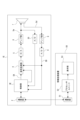
- FIG. 18 is a diagram for explaining an example of the configuration of an audio reproduction system according to a second embodiment, showing an example of the internal configuration of each of the audio device 1E and the information processing device 50 that constitute the audio reproduction system.
- the acoustic device 1E is different in that a control unit 3E is provided instead of the control unit 3D.
- the control unit 3E is capable of performing processing to compensate for changes over time and individual variations in the vibration transmission characteristics.
- the control unit 3E performs processing to transmit information on the vibration transmission characteristics measured via the communication unit 2 to the information processing device 50 in response to a request from the information processing device 50.
- the information processing device 50 is configured as a computer device such as a smartphone, tablet terminal, or personal computer, and includes a communication unit 51, a processor unit 52, and a display unit 53 as shown.
- the processor unit 52 includes a CPU, ROM, RAM, and other memories, and performs overall control of the information processing device and data communication with external devices (particularly, audio device 1E in this embodiment) via the communication unit 51. Note that communication between the communication units 2 and 51 may be either wired or wireless.
- the display unit 53 is configured, for example, as an LCD (Liquid Crystal Display) or an organic EL (Electroluminescence) display, and displays various information on the display screen 53a based on instructions from the processor unit 52.
- the display unit 53 is also capable of displaying various operation menus, icons, messages, etc., i.e., a GUI, based on instructions from the processor unit 52.
- a management app for the audio device 1E is installed in the information processing device 50, for example, to enable various operations and settings of the audio device 1E.
- This management app enables the user to instruct the audio device 1E to execute processing for compensating for the vibration transmission characteristics as described above.
- this management app causes the processor unit 52 to perform processing to display information related to the status of the audio device 1E, specifically, information related to the measured vibration transmission characteristics, on the display screen 53a.
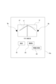
- FIG. 19 shows an example of a GUI displayed on the display screen 53a.
- the vibration transfer characteristic e.g., compliance characteristic
- the measurement result display area Ar displays information on the actually measured vibration transfer characteristic c1 as well as a vibration transfer characteristic c2 as a comparison target.
- the vibration transfer characteristic c2 for example, an average value of the vibration transfer characteristics measured for multiple acoustic devices 1E at the time of shipment from the factory or the like can be displayed.
- buttons B1 and B2 are displayed on the screen. These buttons function as a button to instruct the user to measure the vibration transmission characteristics and a button to instruct the user to execute processing to compensate for the vibration transmission characteristics, respectively.
- the processor unit 52 can also detect an abnormality in the vibration transmission system (the diaphragm 10 and the movable part 11) in the acoustic device 1E based on the measurement results of the vibration transmission characteristics by the acoustic device 1E.
- this abnormality it is considered that the processor unit 52 performs a process of displaying notification information for notifying the abnormality on the display screen 53a.
- a report button B3 as shown in FIG. 19 may be provided so that the occurrence of the abnormality can be reported to the manufacturer or the like based on a user operation.
- the information processing device 50 includes the display unit 53 .
- the display unit 53 may be externally attached to the information processing device 50 .
- the processor unit 52 that performs the GUI display process is provided in a device separate from the audio device 1E, but a configuration in which the GUI display process is performed by the control unit 3E of the audio device 1E is also conceivable.
- GUI display method is not limited to the above example.
- the GUI screen display e.g., the types and arrangement of various buttons, size adjustment of the measurement result display area Ar, zooming in and out, etc.
- the GUI screen display may be changed as desired by the user.
- the measurement data acquired for each model can be used as reference data for aging, for example. It is also possible to store the measurement data on the cloud and share the data with headphone and earphone design manufacturers, mold manufacturers, and component manufacturers. It is also possible to provide the measurement data to such businesses via the cloud, either for a fee or free of charge.
- the present technology is not limited to the specific examples described above, and various modified configurations can be adopted.
- the structure of the magnetic circuit section corresponding to the case where the shape of the diaphragm 10 viewed from above is substantially circular has been described, but the shape of the diaphragm 10 viewed from above is not limited to being substantially circular, and may be other shapes, such as an ellipse, polygon, rectangle, triangle, etc.
- the shapes of the components of the magnetic circuit section such as the top plate section 18 and the pole piece section 19, are not limited to the annular or circular shapes exemplified, and may be other shapes.
- the structure of the magnetic circuit part according to the present technology (a structure in which a protrusion 18b is provided and the wound parts of the first coil and the second coil face the protruding side) is applied to a moving coil type speaker (sound reproduction device), but the structure of the magnetic circuit part according to the present technology can also be applied to a moving coil type microphone.
- a moving coil microphone is based on the same principle and structure as a moving coil speaker, and the structure of the magnetic circuit part of this technology can be used as is.
- one example of use is to use both the first coil and the second coil as inputs, inputting each to an individual A/D converter, and switching the signal (sound pickup signal) used for large and small amplitudes to expand the dynamic range.
- one coil can be used as a drive coil, in which case it can be controlled to move in the opposite direction to the direction in which the diaphragm moves in response to the sound field, thereby reducing distortion caused by excessive input.
- a drive coil in this way, it is also possible to measure vibration transmission characteristics and perform compensation processing for changes over time and individual variations in vibration transmission characteristics based on the measurement results, just as in the case of a speaker.
- This technology can also be applied to hearing aids (hearing devices) and sound collectors (specifically, the speaker part of a sound collector).
- the first acoustic device (1, 1D, 1E) as an embodiment includes a diaphragm (10), a movable part (11) having a coil and connected to the diaphragm, and a magnetic circuit part (15, 15A, 15B) having a magnet (16) and a yoke (17, 17A, 17B) and generating a magnetic force acting on the coil, and the magnetic circuit part has a top plate part (18, 18A) as a part of the yoke, the top plate part having an upper surface part (18a) located on the magnet and extending in a direction substantially perpendicular to the movable direction of the movable part, the top plate part has a protruding part (18b) protruding downward from an inner edge part or an outer edge part of the upper surface part, the movable part has a first coil and a second coil as coils, and the wound portions of the first coil and the second coil in the movable part face the protruding side
- the protruding portion on the top plate portion as described above and making the wound portions of the first coil and the second coil in the movable portion face the protruding side surface of the top plate portion, it becomes possible to realize the magnetic circuits of the first coil and the second coil using a common magnet and yoke, which means that it becomes possible to eliminate the need to provide a magnet and yoke for each coil. Therefore, for a moving coil type acoustic device, it is possible to suppress the increase in size and weight that would occur if multiple coils were provided in the moving part.
- one of the first and second coils is a driving coil for driving the diaphragm, and the other is a sensing coil for detecting the movement of the diaphragm.
- This makes it possible to drive the diaphragm based on detection information about the movement of the diaphragm. Therefore, this is suitable for performing control for correcting distortion of the diaphragm, such as MFB control.
- the first audio device also includes a communication unit that communicates with an external device. This makes it possible to transmit information relating to the movement of the diaphragm to an external device in response to the case where one of the first and second coils is a sensing coil.
- the first acoustic device as the embodiment may be configured as a speaker device. This makes it possible to suppress an increase in size and weight of an audio device serving as a speaker device on which MFB control is performed.
- the first acoustic device as an embodiment may be configured as an earphone, a headphone, a hearing aid, or a sound collector. This makes it possible to suppress increases in size and weight in acoustic devices such as earphones, headphones, hearing aids, and sound collectors that would occur if multiple coils were provided in the movable part.
- the support for the first coil and the support for the second coil are the same. If the first and second coils were wound on separate bobbins, for example, and the supports for the first and second coils were separate, a difference in movement would occur between the driving coil and the sensing coil, making it difficult for the sensing coil to properly detect the movement of the diaphragm. In contrast, if the supports for the first and second coils are the same as above, it is possible to prevent a difference in movement between the driving coil and the sensing coil, and it is possible to properly detect the movement of the diaphragm by the sensing coil. Therefore, the accuracy of detection of the movement of the diaphragm by the sensing coil can be improved.
- the first coil and the second coil are wound around the same bobbin (12). This makes the supports for the first and second coils the same, preventing any difference in movement between the driving coil and the sensing coil. Therefore, the accuracy of detection of the movement of the diaphragm by the sensing coil can be improved.
- the winding directions of the first coil and the second coil are opposite to each other.
- the electromotive force generated in the sensing coil as the movable part moves and the electromotive force generated in the sensing coil as the drive current flows through the drive coil have opposite polarities. Therefore, it is possible to reduce the voltage change width of the sensing signal from the sensing coil when the movable part moves.
- the first coil and the second coil are wound at a distance from each other in the vertical direction. This reduces the electromotive force generated in the sensing coil when a drive current flows through the drive coil. Therefore, the accuracy of detection of the movement of the diaphragm by the sensing coil can be improved. Furthermore, by separating the first coil and the second coil, it is possible to prevent the driving coil from overlapping with an area in the magnetic circuit portion that has magnetic flux density distribution characteristics for sensing, or conversely, to prevent the sensing coil from overlapping with an area that has magnetic flux density distribution characteristics for driving. Therefore, it is possible to improve both the driving efficiency and driving performance of the diaphragm and the detection accuracy of the movement of the diaphragm.
- the first coil and the second coil are wound integrally by a bobbinless winding method. Since no bobbin is required, the device can be made smaller and lighter.
- the magnetic circuit portion is an internal magnet type or an external magnet type magnetic circuit portion (15A, 15). This makes it possible to suppress increases in size and weight in an audio device equipped with an internal magnet type or external magnet type magnetic circuit section that would occur if multiple coils were provided in the movable section.
- the magnetic circuit section is an internal/external magnet type magnetic circuit section (15B). This makes it possible to suppress an increase in size and weight of an audio device equipped with an internal/external magnet type magnetic circuit section, which would occur if multiple coils were provided in the movable section.
- the first acoustic device includes an electric circuit section (signal processing sections 4, 4C) that generates a drive signal for the drive coil based on a sensing signal from the sensing coil. This makes it possible to realize signal processing for correcting distortion of the diaphragm, such as MFB control.
- the electrical circuit unit has a feedback control unit (27, 27C) that processes an acoustic signal using a feedback loop to which a sensing signal is input, and a feedforward control unit (28) that performs arithmetic processing using predetermined coefficients on the acoustic signal input to the feedback loop.
- a feedforward control unit in addition to a feedback control unit that performs feedback control based on the sensing signal from the sensing coil, as in conventional MFB control, it becomes possible to correct distortion that cannot be corrected by the feedback control unit alone. Therefore, the accuracy of distortion correction can be improved.
- the magnetic circuit section has the characteristic that a peak of the r-direction magnetic flux density is obtained near the winding portion of the driving coil, and the distribution of the r-direction magnetic flux density is flat near the winding portion of the sensing coil (see Figure 11). This makes it possible to provide a magnetic flux density distribution suitable for the application of each coil in the arrangement area of each coil, without providing a magnet and a yoke for each coil.
- a second acoustic device (1, 1D, 1E) as an embodiment includes a diaphragm (10), a movable part (11) having a driving coil (13) for driving the diaphragm and a sensing coil (14) for detecting movement of the diaphragm and connected to the diaphragm, a magnetic circuit part (15, 15A, 15B) having a magnet (16) and a yoke (17, 17A, 17B) and generating a magnetic force acting on the driving coil and a magnetic force acting on the sensing coil, and an electric circuit part (signal processing part 4, 4C) that generates a drive signal for the driving coil based on a sensing signal from the sensing coil, and the electric circuit part includes a feedback control part (27, 27C) having a feedback loop that processes an acoustic signal based on the sensing signal, and a feedforward control part (28) that performs arithmetic processing using a predetermined coefficient on the acoustic signal input to the feedback loop
- the device By configuring the device to include a feedforward control unit in addition to a feedback control unit that performs feedback control based on the sensing signal of the sensing coil, as in conventional MFB control, it becomes possible to correct distortion that cannot be corrected by the feedback control unit alone. Therefore, the accuracy of distortion correction can be improved.
- the signal processing method as an embodiment is a signal processing method in an acoustic device that includes a diaphragm, a movable part connected to the diaphragm and having a driving coil for driving the diaphragm and a sensing coil for detecting movement of the diaphragm, a magnetic circuit part that has a magnet and a yoke and generates a magnetic force acting on the driving coil and a magnetic force acting on the sensing coil, and an electric circuit part that generates a drive signal for the driving coil based on a sensing signal from the sensing coil, in which the electric circuit part performs feedback control that processes the acoustic signal using a feedback loop to which the sensing signal is input, and feedforward control that performs arithmetic processing using predetermined coefficients on the acoustic signal input to the feedback loop.
- a display method as an embodiment is a display method that displays information indicating the vibration transmission characteristics of an acoustic device measured based on a detection signal of the sensing coil in an acoustic device comprising: a diaphragm; a movable part having a coil and connected to the diaphragm; and a magnetic circuit part having a magnet and a yoke and generating a magnetic force acting on the coil, wherein the magnetic circuit part has a top plate part as part of the yoke, the top plate part having an upper surface part located on the magnet and extending in a direction approximately perpendicular to the moving direction of the movable part, and the top plate part has a protrusion part protruding downward from an inner edge part or an outer edge part of the upper surface part, the movable part has a driving coil for driving the diaphragm as a coil and a sensing coil for detecting movement of the diaphragm, and the wound portions of the driving coil and the sensing coil
- the present technology can also be configured as follows.
- the movable portion has a first coil and a second coil as the coil, an acoustic device, wherein a wound portion of the first coil and the second coil in the movable portion faces a protruding side surface, which is a side surface of the top plate portion on which the protruding portion is formed.
- the audio device according to (2) further comprising a communication unit for communicating with an external device.
- the magnetic circuit portion includes: The acoustic device described in any one of (2) to (15) has a characteristic that a peak of r-direction magnetic flux density is obtained near the winding portion of the driving coil, and the distribution of r-direction magnetic flux density is flat near the winding portion of the sensing coil.
- a diaphragm a movable portion having a driving coil for driving the diaphragm and a sensing coil for detecting the movement of the diaphragm and connected to the diaphragm; a magnetic circuit section having a magnet and a yoke and generating a magnetic force acting on the driving coil and a magnetic force acting on the sensing coil; an electric circuit unit that generates a drive signal for the drive coil based on a sensing signal from the sensing coil;
- the electrical circuit unit includes a feedback control unit having a feedback loop that processes an acoustic signal based on the sensing signal, and a feedforward control unit that performs arithmetic processing using a predetermined coefficient on the acoustic signal input to the feedback loop.
- the feedback control unit is The acoustic device according to (17), further comprising a conversion filter unit that generates a signal based on a drive signal of the drive coil to cancel an error that occurs in the sensing signal due to magnetic coupling between the drive coil and the sensing coil.
- a signal processing method for an audio device including a diaphragm, a movable section having a driving coil for driving the diaphragm and a sensing coil for detecting movement of the diaphragm and connected to the diaphragm, a magnetic circuit section having a magnet and a yoke and generating a magnetic force acting on the driving coil and a magnetic force acting on the sensing coil, and an electric circuit section generating a driving signal for the driving coil based on a sensing signal from the sensing coil, comprising:
- the signal processing method performs, in the electric circuit section, feedback control for processing an acoustic signal using a feedback loop to which the sensing signal is input, and feedforward control for performing arithmetic processing using a predetermined coefficient on the acoustic signal input to the feedback loop.
- a display method for an acoustic device comprising: a diaphragm, a movable part having a coil and connected to the diaphragm, and a magnetic circuit part having a magnet and a yoke and generating a magnetic force acting on the coil, wherein the magnetic circuit part has a top plate part as part of the yoke, the top plate part having an upper surface part located on the magnet and extending in a direction approximately perpendicular to the moving direction of the movable part, the top plate part having a protrusion protruding downward from an inner edge or an outer edge part of the upper surface part, the movable part has as its coils a driving coil for driving the diaphragm and a sensing coil for detecting movement of the diaphragm, wherein the wound portions of the driving coil and the sensing coil in the movable part face a protruding side surface, which is the side surface on which the protrusion is formed of the top plate part, the display method displaying
Landscapes
- Physics & Mathematics (AREA)
- Engineering & Computer Science (AREA)
- Acoustics & Sound (AREA)
- Signal Processing (AREA)
- Circuit For Audible Band Transducer (AREA)
Priority Applications (3)
| Application Number | Priority Date | Filing Date | Title |
|---|---|---|---|
| CN202480019286.XA CN120898434A (zh) | 2023-03-23 | 2024-03-06 | 音频设备、信号处理方法和显示方法 |
| JP2025508300A JPWO2024195543A1 (https=) | 2023-03-23 | 2024-03-06 | |
| DE112024001394.5T DE112024001394T5 (de) | 2023-03-23 | 2024-03-06 | Akustische vorrichtung, signalverarbeitungsverfahren und anzeigeverfahren |
Applications Claiming Priority (2)
| Application Number | Priority Date | Filing Date | Title |
|---|---|---|---|
| JP2023-046359 | 2023-03-23 | ||
| JP2023046359 | 2023-03-23 |
Publications (1)
| Publication Number | Publication Date |
|---|---|
| WO2024195543A1 true WO2024195543A1 (ja) | 2024-09-26 |
Family
ID=92842051
Family Applications (1)
| Application Number | Title | Priority Date | Filing Date |
|---|---|---|---|
| PCT/JP2024/008526 Ceased WO2024195543A1 (ja) | 2023-03-23 | 2024-03-06 | 音響装置、信号処理方法、表示方法 |
Country Status (4)
| Country | Link |
|---|---|
| JP (1) | JPWO2024195543A1 (https=) |
| CN (1) | CN120898434A (https=) |
| DE (1) | DE112024001394T5 (https=) |
| WO (1) | WO2024195543A1 (https=) |
Citations (8)
| Publication number | Priority date | Publication date | Assignee | Title |
|---|---|---|---|---|
| JPH06327095A (ja) * | 1993-05-13 | 1994-11-25 | Matsushita Electric Ind Co Ltd | スピーカ |
| JPH09289699A (ja) * | 1996-04-24 | 1997-11-04 | Sony Corp | スピーカ装置 |
| JP2001197585A (ja) * | 2000-01-14 | 2001-07-19 | Sony Corp | 周波数特性調整システム、音響装置および周波数特性調整方法 |
| WO2003010998A1 (fr) * | 2001-07-23 | 2003-02-06 | Toshio Chikama | Protection magnetique de bobine de lecture de haut-parleur |
| JP2007005845A (ja) * | 2005-06-21 | 2007-01-11 | Hosiden Corp | ボイスコイル並びにそのボイスコイルを有するスピーカ |
| JP2012186676A (ja) * | 2011-03-07 | 2012-09-27 | Sony Corp | 信号処理装置および信号処理方法 |
| JP2013143667A (ja) * | 2012-01-11 | 2013-07-22 | Panasonic Corp | スピーカ用磁気回路およびこれを用いたスピーカ |
| JP2019220924A (ja) * | 2018-06-22 | 2019-12-26 | ヤマハ株式会社 | 装着型音響出力装置及び装着型音響出力装置の駆動制御方法 |
-
2024
- 2024-03-06 JP JP2025508300A patent/JPWO2024195543A1/ja active Pending
- 2024-03-06 CN CN202480019286.XA patent/CN120898434A/zh active Pending
- 2024-03-06 DE DE112024001394.5T patent/DE112024001394T5/de active Pending
- 2024-03-06 WO PCT/JP2024/008526 patent/WO2024195543A1/ja not_active Ceased
Patent Citations (8)
| Publication number | Priority date | Publication date | Assignee | Title |
|---|---|---|---|---|
| JPH06327095A (ja) * | 1993-05-13 | 1994-11-25 | Matsushita Electric Ind Co Ltd | スピーカ |
| JPH09289699A (ja) * | 1996-04-24 | 1997-11-04 | Sony Corp | スピーカ装置 |
| JP2001197585A (ja) * | 2000-01-14 | 2001-07-19 | Sony Corp | 周波数特性調整システム、音響装置および周波数特性調整方法 |
| WO2003010998A1 (fr) * | 2001-07-23 | 2003-02-06 | Toshio Chikama | Protection magnetique de bobine de lecture de haut-parleur |
| JP2007005845A (ja) * | 2005-06-21 | 2007-01-11 | Hosiden Corp | ボイスコイル並びにそのボイスコイルを有するスピーカ |
| JP2012186676A (ja) * | 2011-03-07 | 2012-09-27 | Sony Corp | 信号処理装置および信号処理方法 |
| JP2013143667A (ja) * | 2012-01-11 | 2013-07-22 | Panasonic Corp | スピーカ用磁気回路およびこれを用いたスピーカ |
| JP2019220924A (ja) * | 2018-06-22 | 2019-12-26 | ヤマハ株式会社 | 装着型音響出力装置及び装着型音響出力装置の駆動制御方法 |
Also Published As
| Publication number | Publication date |
|---|---|
| CN120898434A (zh) | 2025-11-04 |
| JPWO2024195543A1 (https=) | 2024-09-26 |
| DE112024001394T5 (de) | 2026-01-15 |
Similar Documents
| Publication | Publication Date | Title |
|---|---|---|
| JP6997478B1 (ja) | アンプ装置、オーディオ装置、及びアンプ装置の制御方法 | |
| US9307321B1 (en) | Speaker distortion reduction | |
| US9628928B2 (en) | Speaker control device | |
| JPH0591592A (ja) | 永久磁石による変換 | |
| JP6363792B2 (ja) | 電気音響変換装置 | |
| US4256923A (en) | Sound reproducing system utilizing motional feedback and integrated magnetic structure | |
| JP6096542B2 (ja) | マルチコイル、ボイスコイルおよびこれを用いた電気音響変換装置 | |
| US20190141453A1 (en) | Differential speaker apparatus having motion feedback function | |
| JP2016225857A (ja) | スピーカ | |
| CN103096211A (zh) | 麦克风的滤波器电路 | |
| US4295011A (en) | Linear excursion-constant inductance loudspeaker | |
| WO2024195543A1 (ja) | 音響装置、信号処理方法、表示方法 | |
| JPH10304493A (ja) | 電気−音響変換装置及び音響−電気変換装置 | |
| CN209120479U (zh) | 多体扬声器 | |
| CN103067835A (zh) | 动圈式扬声器及其制造方法 | |
| CN121970372A (zh) | 扬声器模块和系统 | |
| JP2008278235A (ja) | スピーカ用磁気回路及びスピーカ | |
| JP2019068147A (ja) | 速度検出回路および駆動制御装置 | |
| JP2006527933A (ja) | 非励振磁気回路による低インダクタンス電磁ドライバー | |
| CN107509131A (zh) | 一种具有复合音圈结构的动圈式耳机 | |
| JP4625427B2 (ja) | スピーカー | |
| JPWO2017104124A1 (ja) | 電気音響変換器 | |
| CN107534814B (zh) | 扬声器装置、以及扬声器装置的音质改善方法 | |
| JP2019220924A (ja) | 装着型音響出力装置及び装着型音響出力装置の駆動制御方法 | |
| CN103763666B (zh) | 一种分频式平板耳机 |
Legal Events
| Date | Code | Title | Description |
|---|---|---|---|
| 121 | Ep: the epo has been informed by wipo that ep was designated in this application |
Ref document number: 24774683 Country of ref document: EP Kind code of ref document: A1 |
|
| ENP | Entry into the national phase |
Ref document number: 2025508300 Country of ref document: JP Kind code of ref document: A |
|
| WWE | Wipo information: entry into national phase |
Ref document number: 2025508300 Country of ref document: JP |
|
| WWE | Wipo information: entry into national phase |
Ref document number: 202480019286.X Country of ref document: CN |
|
| WWE | Wipo information: entry into national phase |
Ref document number: 112024001394 Country of ref document: DE |
|
| WWP | Wipo information: published in national office |
Ref document number: 202480019286.X Country of ref document: CN |
|
| WWP | Wipo information: published in national office |
Ref document number: 112024001394 Country of ref document: DE |
|
| 122 | Ep: pct application non-entry in european phase |
Ref document number: 24774683 Country of ref document: EP Kind code of ref document: A1 |