WO2024195361A1 - 作成支援方法、プログラム、及び、作成支援装置 - Google Patents
作成支援方法、プログラム、及び、作成支援装置 Download PDFInfo
- Publication number
- WO2024195361A1 WO2024195361A1 PCT/JP2024/004841 JP2024004841W WO2024195361A1 WO 2024195361 A1 WO2024195361 A1 WO 2024195361A1 JP 2024004841 W JP2024004841 W JP 2024004841W WO 2024195361 A1 WO2024195361 A1 WO 2024195361A1
- Authority
- WO
- WIPO (PCT)
- Prior art keywords
- curve
- sections
- section
- display unit
- displayed
- Prior art date
- Legal status (The legal status is an assumption and is not a legal conclusion. Google has not performed a legal analysis and makes no representation as to the accuracy of the status listed.)
- Ceased
Links
Images





Classifications
-
- B—PERFORMING OPERATIONS; TRANSPORTING
- B23—MACHINE TOOLS; METAL-WORKING NOT OTHERWISE PROVIDED FOR
- B23Q—DETAILS, COMPONENTS, OR ACCESSORIES FOR MACHINE TOOLS, e.g. ARRANGEMENTS FOR COPYING OR CONTROLLING; MACHINE TOOLS IN GENERAL CHARACTERISED BY THE CONSTRUCTION OF PARTICULAR DETAILS OR COMPONENTS; COMBINATIONS OR ASSOCIATIONS OF METAL-WORKING MACHINES, NOT DIRECTED TO A PARTICULAR RESULT
- B23Q15/00—Automatic control or regulation of feed movement, cutting velocity or position of tool or work
-
- G—PHYSICS
- G05—CONTROLLING; REGULATING
- G05B—CONTROL OR REGULATING SYSTEMS IN GENERAL; FUNCTIONAL ELEMENTS OF SUCH SYSTEMS; MONITORING OR TESTING ARRANGEMENTS FOR SUCH SYSTEMS OR ELEMENTS
- G05B19/00—Program-control systems
- G05B19/02—Program-control systems electric
- G05B19/18—Numerical control [NC], i.e. automatically operating machines, in particular machine tools, e.g. in a manufacturing environment, so as to execute positioning, movement or co-ordinated operations by means of program data in numerical form
-
- G—PHYSICS
- G05—CONTROLLING; REGULATING
- G05B—CONTROL OR REGULATING SYSTEMS IN GENERAL; FUNCTIONAL ELEMENTS OF SUCH SYSTEMS; MONITORING OR TESTING ARRANGEMENTS FOR SUCH SYSTEMS OR ELEMENTS
- G05B19/00—Program-control systems
- G05B19/02—Program-control systems electric
- G05B19/18—Numerical control [NC], i.e. automatically operating machines, in particular machine tools, e.g. in a manufacturing environment, so as to execute positioning, movement or co-ordinated operations by means of program data in numerical form
- G05B19/416—Numerical control [NC], i.e. automatically operating machines, in particular machine tools, e.g. in a manufacturing environment, so as to execute positioning, movement or co-ordinated operations by means of program data in numerical form characterised by control of velocity, acceleration or deceleration
Definitions
- This disclosure relates to a creation support method, a program, and a creation support device. More specifically, this disclosure relates to a creation support method, a program, and a creation support device that support the creation of a CAM curve, which is a graph that defines the slave axis position relative to the master axis position.
- the electronic cam control method described in Patent Document 1 has a synchronous control section in which the slave shaft, which is the object of control, is controlled to operate in synchronization with the main shaft position, and an asynchronous control section in which the slave shaft, which is the object of control, is controlled to operate asynchronously with the main shaft position from the end position of the synchronous control section to the start position of the next synchronous control section, and by making the acceleration of the electronic cam approach zero near the change point where the asynchronous control section and the synchronous control section switch, the operation of the electronic cam near the change point is smoothly controlled.
- the control method described in Patent Document 1 can smoothly control the operation of the electronic cam near the change point where the asynchronous control section switches to the synchronous control section.
- it cannot suppress the slave axis acceleration throughout the entire operation of the electronic cam. This causes a problem in that the slave axis acceleration increases, making it easier for vibrations and shocks to occur in the machine driven by the slave axis.
- This disclosure has been made in consideration of the above-mentioned reasons.
- the purpose of this disclosure is to provide a creation support method, program, and creation support device that can support the creation of a cam curve in which the slave axis acceleration is suppressed throughout the entire range of the cam curve without the need for complicated operations.
- a creation support method supports the creation of a CAM curve representing a slave axis position relative to a master axis position.
- the creation support method includes a display control process, a first reception process, and a generation process.
- an axis defining the master axis position in a graph is divided into a plurality of sections, and the CAM curve, the velocity curve representing the slave axis velocity relative to the master axis position, and the acceleration curve representing the slave axis acceleration relative to the master axis position are each displayed on a display unit so as to be continuous at the division positions of the plurality of sections, and a first user interface element that receives a first operation for changing the division position is displayed on the display unit.
- the first reception process the first operation on the first user interface element is received.
- the generation process the division position is changed based on the first operation received in the first reception process, and the section shapes of the plurality of sections of each of the CAM curve, the velocity curve, and the acceleration curve displayed on the display unit are regenerated based on the changed division position.
- the acceleration curve is displayed on the display unit so that the section shape of the acceleration curve in a first predetermined section among the multiple sections does not change with respect to the main axis position.
- a program according to another aspect of the present disclosure is a program that causes a computer to execute the above-mentioned creation support method.
- a creation support device supports the creation of a CAM curve representing a slave axis position relative to a master axis position.
- the creation support device includes a display control unit, a first reception processing unit, and a generation unit.
- the display control unit divides the master axis position in a graph into a plurality of sections, and displays the CAM curve, the velocity curve representing the slave axis velocity relative to the master axis position, and the acceleration curve representing the slave axis acceleration relative to the master axis position on the display unit so as to be continuous at the division positions of the plurality of sections, and displays a first user interface element on the display unit that accepts a first operation for changing the division position.
- the first reception processing unit accepts the first operation on the first user interface element.
- the generation unit changes the division position based on the first operation accepted by the first reception processing unit, and regenerates the section shapes of the plurality of sections of each of the CAM curve, the velocity curve, and the acceleration curve displayed on the display unit based on the changed division position.
- the display control unit causes the display unit to display the acceleration curve so that the section shape of the acceleration curve in a first predetermined section among the multiple sections does not change with respect to the spindle position.
- the creation support method, program, and creation support device disclosed herein have the advantage of being able to support the creation of a cam curve in which the slave axis acceleration is suppressed throughout the entire range of the cam curve, without the need for complicated operations.
- FIG. 1 is an explanatory diagram for explaining a general electronic cam.
- FIG. 2 is a configuration diagram showing the configuration of a creation support device to which the creation support method according to the embodiment is applied.
- FIG. 3 is an explanatory diagram illustrating an example of a second UI element used in the creation support method.
- FIG. 4 is an explanatory diagram illustrating the state of the display screen when 5 division is selected in the second UI element used in the creation support method.
- FIG. 5 is an explanatory diagram illustrating the state of the display screen when 7 division is selected in the second UI element used in the creation support method.
- FIG. 6 is an explanatory diagram illustrating an example of a first UI element used in the creation support method.
- FIG. 1 is an explanatory diagram for explaining a general electronic cam.
- FIG. 2 is a configuration diagram showing the configuration of a creation support device to which the creation support method according to the embodiment is applied.
- FIG. 3 is an explanatory diagram illustrating an example of a second UI element
- FIG. 7 is an explanatory diagram for explaining an example of an operation of the first UI element used in the creation support method.
- FIG. 8 is a flowchart for explaining the above-mentioned creation support method (operation of the operation support device).
- FIG. 9 is an explanatory diagram illustrating a first UI element of the creation support method according to the first modification.
- FIG. 10 is an explanatory diagram illustrating a first numerical input field in the creation support method according to the second modification.
- FIG. 11 is an explanatory diagram for explaining an example of a display screen in the above-mentioned creation support method.
- FIG. 12 is an explanatory diagram illustrating a second numerical input field in the creation support method according to the third modified example.
- FIG. 13 is an explanatory diagram for explaining an example of operation of the second numerical input field in the creation support method according to the third modified example.
- FIG. 14 is an explanatory diagram illustrating a first UI element of the creation support method according to the fourth modification.
- Embodiment (1-1) Overview A creation assistance method according to this embodiment assists in the creation of a cam curve used in an electronic cam.
- An electronic cam is a device that computerizes the functions of a mechanical cam.
- a mechanical cam is a component that displaces a slave shaft according to the rotational position of a motor's rotating shaft (main shaft).
- a cam curve (graph) is set in advance that represents the relationship between the slave shaft position, which is the displacement position of the slave shaft, and the main shaft position, which is the rotational position of the main shaft.
- the cam curve is set, for example, as a function or a data table.
- the master shaft position is a position signal that serves as a synchronization reference used in electronic cam control.
- the master shaft position is given, for example, by a position signal that indicates the rotational position (master shaft position) of the motor.
- the master shaft position may also be given by a position signal output from an external device such as a pulser or encoder.
- the position signal that indicates the master shaft position may be generated inside the device that constitutes the electronic cam, or may be generated outside the device.
- the master shaft is assumed to be the rotating shaft of the motor. However, the master shaft does not have to be the rotating shaft of the motor, and may be a virtual shaft.
- the slave shaft position is given by a position signal that indicates the displacement position when the slave shaft of the driven object is displaced.
- FIG. 1 is an explanatory diagram for explaining a general electronic cam 1.
- the electronic cam 1 shown in FIG. 1 includes a motor 2, three servo motors 3a, 3b, and 3c, three controllers 4a, 4b, and 4c for controlling the servo motors 3a, 3b, and 3c, and three slave shafts 5a, 5b, and 5c.
- the controllers 4a, 4b, and 4c are set with cam curves 6a, 6b, and 6c for controlling the servo motors 3a, 3b, and 3c to be controlled.
- the cam curves 6a, 6b, and 6c may be the same as each other, or may be different from each other.
- the controllers 4a, 4b, and 4c input a main shaft position P1 indicating the rotation position of the rotating shaft 2a of the motor 2.
- the controllers 4a, 4b, and 4c convert the input main shaft position P1 into the corresponding slave shaft positions a1, a2, and a3 based on the cam curves 6a, 6b, and 6c that are set in advance, respectively.
- the control units 4a, 4b, and 4c rotate the servo motors 3a, 3b, and 3c based on the converted slave shaft positions a1, a2, and a3, respectively.
- This rotation displaces the slave shafts 5a, 5b, and 5c by the slave shaft positions a1, a2, and a3 input to the servo motors 3a, 3b, and 3c, respectively.
- the slave shaft positions a1, a2, and a3 are the rotation shafts of the servo motors 3a, 3b, and 3c, respectively.
- the slave shafts 5a, 5b, and 5c may be other shafts that are displaced by the rotation of the rotation shafts of the servo motors 3a, 3b, and 3c.
- FIG. 1 illustrates an example in which three servo motors 3a, 3b, and 3c are provided. However, the number of servo motors may be less than three or may be four or more.
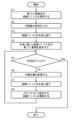
- FIG. 8 is a flowchart explaining the creation support method (operation of the creation support device) according to the embodiment.
- the creation support method according to the embodiment supports the creation of a CAM curve (graph) representing the slave axis position relative to the master axis position.
- the creation support method according to the embodiment includes a display control process (step S4), a first reception process (step S6), and a graph generation process (step S7).
- step S4 an axis defining the master axis position in the graph is divided into a plurality of sections, and the CAM curve, the velocity curve representing the slave axis velocity relative to the master axis position, and the acceleration curve representing the slave axis acceleration relative to the master axis position are displayed on the display unit so as to be continuous at the division positions of the plurality of sections, and a first UI (user interface) element that accepts a first operation for changing the division position is displayed on the display unit.
- step S6 the first operation on the first UI element is accepted.
- step S7 the division position is changed based on the first operation received in the first reception process (step S6), and the section shapes of the cam curve, the velocity curve, and the acceleration curve displayed on the display unit are regenerated in the multiple sections based on the changed division position.
- step S4 the acceleration curve is displayed on the display unit so that the section shape of the acceleration curve in a first predetermined section of the multiple sections does not change with respect to the spindle position.
- the acceleration curve is displayed on the display unit 11 in the display control process (step S4)
- the acceleration curve is displayed in advance in the initial setting so that the section shape of the acceleration curve in the first predetermined section of the multiple sections does not change with respect to the main axis position.
- the division positions of the multiple sections are changed, and the shape of the acceleration curve is corrected in the graph generation process (step S7).
- the slave axis acceleration can be suppressed throughout the entire range of the cam curve. As described above, it is possible to support the creation of a cam curve in which the slave axis acceleration is suppressed throughout the entire range of the cam curve without performing complex operations.
- FIG. 2 is a configuration diagram showing the configuration of a creation support device 10 to which a creation support method according to an embodiment is applied. The configuration of the creation support device 10 according to the embodiment will be described with reference to Fig. 2.
- the creation support device 10 includes a display unit 11, an input unit 12, a memory unit 13, and a processing unit 14.
- FIG. 3 is an explanatory diagram illustrating an example of a second UI element 20 used in the creation support method according to the embodiment.
- the display unit 11 is a display device capable of displaying the curves C1 to C4 (see FIG. 3) required to create the CAM curve C1, the first UI element 30 (described later with reference to FIG. 6), and the second UI element 20.
- the display unit 11 is, for example, a liquid crystal display device.
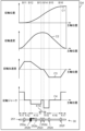
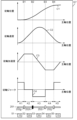
- Curves C1 to C4 include cam curve C1, velocity curve C2, acceleration curve C3, and jerk (jerk) curve C4.
- cam curve C1 is a graph that defines the slave axis position relative to the master axis position.
- Velocity curve C2 is a graph that defines the slave axis speed relative to the master axis position.
- Acceleration curve C3 is a graph that defines the slave axis acceleration relative to the master axis position.
- Jerk curve C4 is a graph that defines the slave axis jerk relative to the master axis position.
- Curves C1 to C4 are each set, for example, as a function or a data table.
- the horizontal axis is the master axis position in the case of cam curve C1, the slave axis speed in the case of velocity curve C2, the slave axis acceleration in the case of acceleration curve C3, and the slave axis jerk in the case of jerk curve C4.
- the creation support device 10 allows the user to change not only the shape of the cam curve C1, but also the shapes of the velocity curve C2 that defines the velocity characteristics of the cam curve C1, the acceleration curve C3 that defines the acceleration characteristics of the cam curve C1, and the jerk curve C4 that defines the jerk characteristics of the cam curve to create the shape of the cam curve C1.
- FIG. 6 is an explanatory diagram illustrating an example of a first UI element 30 used in the creation support method according to the embodiment.
- the first UI element 30 is a UI element for receiving an operation (first operation) for changing the division position of the horizontal axis (main axis position) of the graph.
- the first UI element 30 is a UI element that can be operated by an input operation to the input unit 12.
- the first UI element 30 is, for example, sliders 252a to 252f that are displayed on the display screen of the display unit 11 and can be operated by an input operation to the input unit 12 as shown in FIG. 6.
- the sliders 252a to 252f will be described in detail later.
- the second UI element 20 is a UI element for receiving an operation (second operation) for setting the number of divisions on the horizontal axis (main axis position) of the graph.
- the second UI element 20 is, for example, selection icons 21 to 23 that are displayed on the display unit 11 and allow the number of divisions to be selected by an input operation on the input unit 12. Details of the selection icons 21 to 23 will be described later.
- the input unit 12 is an input device through which a user inputs operations to the creation support device 10.
- the input unit 12 is, for example, an input device such as a keyboard, a mouse, or a touch sensor.
- the touch sensor detects the touch position on the screen of the display unit 11.
- the storage unit 13 stores various programs and data necessary to execute the processing of the creation assistance device 10.
- the storage unit 13 is, for example, composed of a readable/writable non-volatile memory.
- the storage unit 13 is, for example, a flash memory.
- the processing unit 14 is mainly composed of a computer having, for example, a CPU (Central Processing Unit) and memory.
- the processing unit 14 realizes various functions of the processing unit 14 by executing a program stored in the memory with the CPU.
- the program may be recorded in the computer's memory in advance.
- the program may be provided by recording it on a recording medium such as a memory card.
- the program may be provided via a telecommunications line such as the Internet.
- the processing unit 14 controls the display screen of the display unit 11 based on the input operation to the input unit 12, and generates curves C1 to C4 and displays them on the display unit 11.
- the processing unit 14 includes a first reception processing unit 141, a second reception processing unit 142, a display control unit 143, and a graph generation unit (generation unit) 144.
- the first reception processing unit 141 performs processing to receive an operation (first operation) on the first UI element 30 displayed on the display unit 11. More specifically, when the first UI element 30 displayed on the display unit 11 is operated by an input operation on the input unit 12, the first reception processing unit 141 performs processing to receive the operation.
- the second reception processing unit 142 performs processing to receive an operation (second operation) on the second UI element 20 displayed on the display unit 11. More specifically, when the second UI element 20 displayed on the display unit 11 is operated by an input operation on the input unit 12, the second reception processing unit 142 performs processing to receive the operation (operation for setting the number of divisions).
- the display control unit 143 controls the display screen of the display unit 11. More specifically, the display control unit 143 causes the display unit 11 to display the curves C1 to C4, the first UI element 30, and the second UI element 20 generated by the graph generation unit 144.
- the graph generation unit 144 generates curves C1 to C4, which are the base for creating the user's desired CAM curve, as shown in FIG. 3, based on the operations input to the first reception processing unit 141 and the second reception processing unit 142.
- the shapes of the curves C1 to C4 generated at this time are, for example, set in advance as defaults.
- the shapes of the curves C1 to C4 in FIG. 3 are one example.
- the shapes of the curves C1 to C4 are not limited to the shapes in FIG. 3. More specifically, when a second operation is not input to the second reception processing unit 142, the graph generation unit 144 generates the curves C1 to C4 without dividing the horizontal axis (main axis position) of the curves C1 to C4 into multiple sections.
- the display control unit 143 displays the generated curves C1 to C4 on the display unit 11, arranged one above the other.
- the display control unit 143 causes the display unit 11 to display the second UI element 20 (i.e., the UI element that accepts an operation to set the number of divisions of the main axis position) so that it is positioned at a predetermined location on the display screen of the display unit 11 (for example, the location above the top curve C1) before the horizontal axis (main axis position) of the curves C1 to C4 displayed on the display unit 11 is divided.
- the second UI element 20 i.e., the UI element that accepts an operation to set the number of divisions of the main axis position
- the graph generation unit 144 divides the horizontal axis (main axis position) of each of the curves C1 to C4 into the same number of sections (i.e., multiple sections) as the division number set in the second operation.
- the graph generation unit 144 divides the generated curves C1 to C4 in accordance with the division of the horizontal axis (main axis position) of the curves C1 to C4.
- the graph generation unit 144 divides the generated curves C1 to C4 in accordance with the divided sections of the horizontal axis (main axis position) of the curves C1 to C4.
- the graph generation unit 144 generates the curves C1 to C4 so that the curves C1 to C4 are continuous at the division positions (boundaries of each section).
- a shape type is associated with the shape (section shape) within each section of the curves C1 to C4.
- the shape type is the characteristic shape of the section shape of each section of the curves C1 to C4.
- the shape type is, for example, a shape that does not change along the horizontal axis, or a shape that monotonically increases or decreases along the horizontal axis.
- the section shapes of each section of the acceleration curve C3 in particular are associated with the following shape types.
- the graph generating unit 144 generates the acceleration curve C3 such that the section shape of a predetermined section (first predetermined section) among the multiple sections of the horizontal axis (main axis position) of the acceleration curve C3 is a shape (shape type) that does not change with respect to the horizontal axis.
- the first predetermined section is, for example, the second section and the fourth section from the origin side.
- the first predetermined section is, for example, the second section and the sixth section from the origin side.
- the graph generating unit 144 generates the acceleration curve C3 such that the section shape of a predetermined section (second predetermined section) among the multiple sections of the horizontal axis (main axis position) of the acceleration curve C3 is a shape (shape type) that monotonically increases or monotonically decreases with respect to the horizontal axis.
- the second predetermined section is, for example, the first, third, and fifth section from the origin side. If the number of divisions into multiple sections is seven, the second predetermined sections are the first, third, fifth, and seventh sections from the origin side.
- the display control unit 143 causes the display unit 11 to display the curves C1 to C4 divided by the graph generation unit 144 as described above.
- the display control unit 143 causes the first UI element 30 to be displayed at a predetermined location on the display screen of the display unit 11. This makes it possible to change the division position of the horizontal axis of the curves C1 to C4 displayed on the display unit 11 by operating the first UI element 30.
- the graph generation unit 144 regenerates the section shapes of each section of the curves C1 to C4 in accordance with the change in division position.
- the graph generation unit 144 changes the size in the section length direction of the section shape of each section of the curves C1 to C4 in accordance with the change in division position.
- the section shapes of the curves C1 to C4 are regenerated so as to be expanded in the section length direction.
- the section shapes of curves C1 to C4 are regenerated so as to be reduced in the section length direction.
- the display control unit 143 updates the curves C1 to C4 displayed on the display unit 11 to the curves C1 to C4 regenerated by the graph generation unit 144 as described above, and displays them.
- FIG. 4 is an explanatory diagram illustrating the state of the display screen when 5 divisions are selected in the second UI element 20 used in the creation support method according to the embodiment.
- Fig. 5 is an explanatory diagram illustrating the state of the display screen when 7 divisions are selected in the second UI element 20 used in the creation support method according to the embodiment.
- the second UI element 20 is a UI element that receives the setting of the number of divisions of the horizontal axis (main axis position) of the curves C1 to C4.
- the second UI element 20 is displayed on the display screen G1 of the display unit 11.
- the second UI element 20 is displayed on the display unit 11 together with the curves C1 to C4.
- the display screen G1 is vertically long, but the display screen G1 is not limited to being vertically long.
- the curves C1 to C4 are the cam curve C1, the velocity curve C2, the acceleration curve C3, and the jerk curve C4.
- the curves C1 to C4 are displayed in a vertical line on the display screen G1 of the display unit 11. In FIG. 3, the horizontal axis and the curves C1 to C4 are not divided.
- the cam curve C1 is, for example, a curve that smoothly and monotonically increases in an approximately S-shape with respect to the master shaft position from a position where the slave shaft position is zero.
- the velocity curve C2 is the first derivative of the cam curve C1.
- the acceleration curve C3 is the first derivative of the velocity curve C2.
- the jerk curve C4 is the first derivative of the acceleration curve C3.
- the second UI element 20 is displayed at a predetermined location (e.g., above the top curve C1) on the display screen G1 of the display unit 11.
- the second UI element 20 has, for example, one or more selection icons 21-23 (three in FIG. 3).
- the three selection icons 21-23 are selection icons for selecting the number of divisions on the horizontal axis (main axis position) of the curves C1-C4.
- the three selection icons 21-23 can be selected by an input operation to the input unit 12.
- the three selection icons 21-23 are, for example, the selection icon 21 that displays "do not divide", the selection icon 22 that displays "5 divisions", and the selection icon 23 that displays "7 divisions".
- the selection icon 21 has a text section 21b and a selection status display section 21a.
- the selection icon 22 has a text section 22b and a selection status display section 22a.
- the selection icon 23 has a text section 23b and a selection status display section 23a.
- the character sections 21b, 22b, 23b each indicate the number of divisions (for example, no division, 5 divisions, or 7 divisions) of the horizontal axis (main axis position) of the curves C1 to C4.
- the selection status display sections 21a, 22a, 23a each display the selection status (selected or unselected) of the selection icons 21, 22, 23. In FIG. 3, the selection icon 21 displaying "no division” is selected, while the selection icon 22 displaying "5 divisions" and the selection icon 23 displaying "7 divisions" are illustrated as not being selected.
- the display unit 11 When displaying the second UI element 20, the display unit 11 initially displays the display screen G1 shown in FIG. 3. In FIG. 3, the "Do not split” selection icon 21 is initially selected. The user selects either the “5 split” selection icon 22 or the “7 split” selection icon 23 by inputting information into the input unit 12.
- the display screen G2 shown in FIG. 4 is displayed on the display unit 11.
- the horizontal axis (main axis position) of the curves C1 to C4 is divided into five intervals K1 to K5.
- the curves C1 to C4 are also divided into five intervals K1 to K5.
- the graph generation unit 144 divides the horizontal axis (main axis position) of the curves C1 to C4 and the curves C1 to C4 into five intervals K1 to K5.
- the display control unit 143 displays the divided horizontal axes of the curves C1 to C4 and the curves C1 to C4 on the display unit 11.
- the display control unit 143 further displays, on the display screen G2 of the display unit 11, dividing lines B1 to B4 for visualizing the horizontal axes of the curves C1 to C4 and the dividing positions of each of the curves C1 to C4.
- the dividing lines B1 to B4 correspond one-to-one with the dividing positions of the five sections K1 to K5.
- the dividing lines B1 to B4 are displayed so as to be perpendicular to the horizontal axes (main axis positions) of the curves C1 to C4 at the corresponding dividing positions.
- the dividing lines B1 to B4 are displayed across the horizontal axes of the curves C1 to C4.
- the curves C1 to C4 are divided at the positions of the dividing lines B1 to B4.
- the acceleration curve C3 is regenerated so that the section shapes of sections K1 to K5 have the following shapes. That is, the acceleration curve C3 is regenerated so that, among the five sections K1 to K5, the section shapes of sections K2 and K4 (first predetermined section) have a shape that does not change along the horizontal axis, and the section shapes of sections K1, K3, and K5 have a shape that monotonically increases or decreases along the horizontal axis.
- the section shape of section K2 has a flat shape with a positive constant value.
- the section shape of section K4 is changed to a flat shape with a negative constant value.
- the section shapes of sections K1 and K5 are changed to a linearly increasing shape, and the section shape of section K3 is changed to a linearly decreasing shape.
- the acceleration curve C3 is initially regenerated so that the section shapes of sections K1 to K5 have the above-mentioned shapes.
- cam curve C1, velocity curve C2, and jerk curve C4 are regenerated to be consistent with the acceleration curve C3 regenerated as described above.
- FIG. 5 shows the display screen G3 displayed on the display unit 11 when the user selects the selection icon 23 displaying "7 divisions".
- the horizontal axis (main axis position) of the curves C1 to C4 is divided into seven intervals K11 to K17.
- the curves C1 to C4 are also divided into seven intervals K11 to K17. That is, when the user selects the selection icon 23 displaying "7 divisions", the graph generation unit 144 divides the horizontal axis (main axis position) of the curves C1 to C4 and the curves C1 to C4 into seven intervals K11 to K17.
- the display control unit 143 displays the horizontal axis of the divided curves C1 to C4 and the curves C1 to C4 on the display unit 11.
- the display control unit 143 further displays division lines B11 to B16 for visualizing the horizontal axis of the curves C1 to C4 and the division positions of the curves C1 to C4 on the display screen G3 of the display unit 11. Curves C1 to C4 are divided at division lines B11 to B16.
- the acceleration curve C3 is regenerated so that the section shapes of sections K11 to K17 have the following shapes. That is, the acceleration curve C3 is regenerated so that, of the seven sections K11 to K17, the section shapes of sections K12 and K16 (first predetermined section) have a shape that does not change along the horizontal axis, the section shapes of sections K11, K13, K15, and K17 have a shape that monotonically increases or decreases along the horizontal axis, and the section shape of section K14 becomes zero.
- the acceleration curve C3 is regenerated so that, of the seven sections K11 to K17, the section shapes of sections K12 and K16 (first predetermined section) have a shape that does not change along the horizontal axis, the section shapes of sections K11, K13, K15, and K17 have a shape that monotonically increases or decreases along the horizontal axis, and the section shape of section K14 becomes zero.
- the section shape of section K12 becomes a flat shape having a constant positive value
- the section shape of section K16 is changed to a flat shape having a constant negative value
- the section shape of section K14 where the velocity curve C2 is constant becomes zero
- the section shapes of sections K11 and K17 are changed to a linearly monotonically increasing shape
- the section shapes of sections K13 and K15 are changed to a monotonically decreasing shape.
- cam curve C1, velocity curve C2, and jerk curve C4 are regenerated to be consistent with the acceleration curve C3 regenerated as described above.
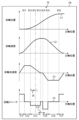
- the first UI element 30 is a UI element that accepts an operation for changing the division position of the horizontal axis (main axis position) of the curves C1 to C4.
- the first UI element 30 is displayed at a predetermined location (for example, below the bottom curve C4) on the display screen G4 of the display unit 11.
- the curves C1 to C4 are divided into seven.
- the first UI element 30 includes a guide portion 251 and one or more (six in FIG. 6) sliders 252a-252f.
- the guide portion 251 defines the movable range of the sliders 252a to 252f.
- the guide portion 251 is disposed parallel to the horizontal axis of the curves C1 to C4.
- the guide portion 251 is set to the same length as the horizontal axis of the curves C1 to C4.
- the sliders 252a to 252f can move between one end and the other end of the horizontal axis of the curves C1 to C4 along the guide portion 251.
- the horizontal axes of the curves C1 to C4 have the same length.
- the origins of the horizontal axes are lined up vertically in a row.
- the six sliders 252a to 252f are provided in the same number as the number of divisions of the horizontal axis of the curves C1 to C4 (i.e., the number of division lines B11 to B16).
- the six sliders 252a to 252f correspond one-to-one to the six division lines B11 to B16, and are positioned directly below the corresponding division lines B11 to B16.
- the sliders 252a to 252f can be moved along the guide section 251 by input operations to the input section 12.
- the sliders 252a to 252f are operation units for moving the corresponding dividing lines B11 to B16 in the horizontal direction of the curves C1 to C4.
- the corresponding dividing lines B11 to B16 move along the guide portion 251 together with the moved sliders 252a to 252f by the same amount as the amount of movement of the moved sliders 252a to 252f.
- the division positions of the multiple sections K11 to K17 move along the guide portion 251. This changes the section length of each of the multiple sections K11 to K17.
- FIG. 7 is an explanatory diagram for explaining an example of the operation of the first UI element 30 used in the creation support method according to the embodiment.
- the division line B12 corresponding to the slider 252b moves to the left together with the slider 252b by the same amount as the movement of the slider 252b.
- the section length of the section K12 becomes shorter, and the section length of the section K13 becomes longer.
- the graph generation unit 144 regenerates the curves C1 to C4 based on the changed sections K11 to K17, and adjusts the section shapes of the changed sections (e.g., K11, K13) for the curves C1 to C4 so that they match the changed section lengths.
- the shape of a predetermined section of the acceleration curve C3 (e.g., sections K12, K16 including a maximum or minimum) is initially set to a shape that does not change along the horizontal axis.
- the length of the predetermined section is changed to adjust the overall shape of the curves C1 to C4.
- the user uses the creation support device 10 to create a cam curve C1 such that the section shape of the predetermined section of the acceleration curve C3 does not change along the horizontal axis.
- the display control unit 143 displays, as the second UI element 20, a number of selection icons 21-23 for selecting the number of divisions of the horizontal axis (spindle position) of the cam curve C1 at predetermined locations on the display screen G1 of the display unit 11 (step S1).
- the display unit 11 displays a selection icon 21 displaying "do not divide,” a selection icon 22 displaying "5 divisions,” and a selection icon 23 displaying "7 divisions.”
- the selection icon 21 displaying "do not divide” is selected.
- the curves C1-C4 before division are displayed one above the other.
- the second UI element 20 is displayed above the top curve C1.
- the user operates the input unit 12 to select the selection icon 22 displaying "5 divisions" or the selection icon 23 displaying "7 divisions" from among the multiple selection icons 21 to 23 displayed on the display unit 11 (step S2).
- the user selects, for example, the selection icon 23 displaying "7 divisions”.
- graph generation unit 144 divides the horizontal axis (main axis position) of curves C1 to C4 into intervals K11 to K17, the same number as the number of divisions selected in step S2 (for example, 7 divisions), as shown in FIG. 6. At that time, graph generation unit 144 divides the horizontal axis (main axis position) of curves C1 to C4 into intervals K11 to K17 using the interval lengths that are initially set as the interval lengths of each of intervals K11 to K17. Graph generation unit 144 regenerates the shapes of curves C1 to C4 based on the divided intervals K11 to K17 (step S3).
- step S3 the curves C1 to C4 are regenerated so that they are continuous at the division positions.
- the acceleration curve C3 is regenerated so that, of the seven sections K11 to K17, the section shapes of sections K12 and K16 are constant (constant) along the horizontal axis (main axis position), the section shapes of sections K11, K13, K15, and K17 are monotonically increasing or decreasing along the horizontal axis, and the section shape of section K14 is zero.
- the other curves C1, C2, and C4 are regenerated so that they are consistent with the acceleration curve C3 regenerated as described above.
- the display control unit 143 updates the curves C1 to C4 displayed on the display screen G4 of the display unit 11 in step S1 to the curves C1 to C4 regenerated in step S3 and displays them (step S4).
- the display control unit 143 displays sliders 252a to 252f and a guide unit 251 as the first UI element 30 at predetermined positions on the display screen G4 of the display unit 11.
- the sliders 252a to 252f are displayed below the bottom curve C4.
- division lines B11 to B16 indicating the division positions are displayed on the display unit 11.
- step S6 the user operates the input unit 12 to change the positions of the sliders 252a to 252f displayed on the display unit 11 in step S4. This change changes the length of each of the sections K11 to K17.
- the user reduces the section length of section K12 and increases the section length of section K13 by moving slider 252b a certain amount to the left, for example, as shown in FIG. 7.
- the graph generation unit 144 changes the division position of the horizontal axis (main axis position) of the curves C1 to C4 based on the change in the position of the slider 252b in step S6. That is, the graph generation unit 144 changes the section length of each of the sections (e.g., K12, K13) on both sides of the slider 252b whose position has been changed, among the multiple sections of the horizontal axis of the curves C1 to C4.
- the graph generation unit 144 regenerates the section shapes of each of the sections K11 to K17 of the curves C1 to C4 based on each of the changed sections K11 to K17 (step S7).
- the curves C1 to C4 are regenerated so that they are continuous at the division positions.
- the acceleration curve C3 is regenerated so that, of the seven sections K11 to K17, the section shapes of sections K12 and K16 are constant (constant) along the horizontal axis (spindle position), the section shapes of sections K11, K13, K15, and K17 are monotonically increasing or decreasing along the horizontal axis, and the section shape of section K14 is zero.
- the display control unit 143 updates the curves C1 to C4 displayed on the display unit 11 in step S4 to the curves C1 to C4 regenerated in step S7 and displays them (step S8).
- the process returns to step S5.
- Steps S5 to S8 are repeated until the curve C1 has the shape desired by the user.
- the curve C1 has the desired shape in step S5 (i.e., the creation of the curve C1 is complete) (step S5: Yes)
- the user inputs an operation to the input unit 12 indicating that the creation of the curve C1 is complete, and the creation of the curve C1 is terminated. Then, the process ends.
- the creation support method supports the creation of a CAM curve C1 representing the slave axis position relative to the master axis position.
- the creation support method includes a display control process (step S4), a first reception process (step S6), and a graph generation process (step S7).
- an axis (horizontal axis) defining the master axis position in the graph is divided into a plurality of sections K1 to K5, K11 to K17, and the CAM curve C1, the velocity curve C2 representing the slave axis speed relative to the master axis position, and the acceleration curve C3 representing the slave axis acceleration relative to the master axis position are displayed on the display unit 11 so as to be continuous at the division positions of the plurality of sections K1 to K5, K11 to K17, respectively, and a first UI element 30 for receiving a first operation for changing the division positions is displayed on the display unit 11.
- a first operation to the first UI element 30 is received.
- step S7 the division position is changed based on the first operation accepted in the first acceptance process (step S6), and based on the changed division position, section shapes in the multiple sections K1 to K5, K11 to K17 of the cam curve C1, velocity curve C2, and acceleration curve C3 displayed on the display unit 11 are regenerated.
- step S4 the acceleration curve C3 is displayed on the display unit 11 so that the section shapes of the acceleration curve C3 in first predetermined sections K2, K4, K12, and K16 of the multiple sections K1 to K5, K11 to K17 do not change with respect to the spindle position.
- the acceleration curve C3 is displayed on the display unit 11 in the display control process (step S4)
- the acceleration curve C3 is displayed on the display unit 11 in advance by default so that the section shape of the acceleration curve C3 in the first predetermined section K2, K4, K12, and K16 of the multiple sections K1 to K5 and K11 to K17 does not change with respect to the spindle position.
- the first reception process step S6
- the division positions of the multiple sections K1 to K5 and K11 to K17 are changed based on the user's operation, and the shape of the acceleration curve C3 is modified in the graph generation process (step S7).
- CAM curve C1 By creating the CAM curve C1 in this manner, it is possible to easily (i.e., without performing complicated operations) create a CAM curve C1 in which the section shape of the acceleration curve C3 in the first predetermined section K2, K4, K12, and K16 of the multiple sections K1 to K5 and K11 to K17 does not change with respect to the spindle position.
- the section shape of the acceleration curve C3 in the first predetermined section K2, K4, K12, and K16 of the multiple sections K1 to K5 and K11 to K17 have a shape that does not change with respect to the main shaft position, it is possible to suppress the slave axis acceleration throughout the entire range of the cam curve C1.
- the creation support device 10 supports the creation of a CAM curve C1 representing the slave axis position relative to the master axis position.
- the creation support device 10 includes a display control unit 143, a first reception processing unit 141, and a graph generating unit 144.
- the display control unit 143 divides the master axis position in the graph into a plurality of sections K1-K5, K11-K17, and displays the CAM curve C1, the velocity curve C2 representing the slave axis speed relative to the master axis position, and the acceleration curve C3 representing the slave axis acceleration relative to the master axis position on the display unit 11 so as to be continuous at the division positions of the plurality of sections K1-K5, K11-K17, and displays on the display unit 11 a first UI element 30 that accepts a first operation for changing the division position.
- the first reception processing unit 141 accepts the first operation on the first UI element 30.
- the graph generation unit 144 changes the division position based on the first operation accepted by the first reception processing unit 141, and based on the changed division position, regenerates the section shapes in the multiple sections K1 to K5, K11 to K17 of the cam curve C1, velocity curve C2, and acceleration curve C3 displayed on the display unit 11.
- the display control unit 143 displays the acceleration curve C3 on the display unit 11 so that the section shapes of the acceleration curve C3 in the first predetermined sections K2, K4, K12, and K16 of the multiple sections K1 to K5, K11 to K17 do not change with respect to the spindle position.
- This configuration makes it possible to provide a creation support device that achieves the same effects as the creation support method described above.
- a program causes a computer to execute the above-mentioned creation support method.
- the non-transitory recording medium temporarily records a program that causes a computer to execute the above-mentioned creation assistance method.
- the first UI element 30 includes sliders 252a to 252f.
- Fig. 9 is an explanatory diagram illustrating the first UI element 30 of the creation support method according to Modification 1. As shown in Fig. 9, Modification 1 illustrates an example in which the first UI element 30 includes split bars (e.g., B11 to B16) as dividing lines.
- the split bars B11 to B16 correspond one-to-one to the division positions of the seven sections K11 to K17.
- the split bars B11 to B16 are displayed so as to be perpendicular to the horizontal axis (main axis position) of the curves C1 to C4 at the corresponding division positions.
- the split bars B11 to B16 correspond one-to-one to the division positions of the seven sections K11 to K17.
- the split bars B11 to B16 are displayed so as to be perpendicular to the horizontal axis (main axis position) of the curves C1 to C4 at the corresponding division positions.
- the split bars B11 to B16 are displayed across the horizontal axes of the curves C1 to C4.
- the curves C1 to C4 are divided at the positions of the split bars B11 to B16.
- the split bars are dividing lines (e.g. B11 to B16) that can be moved by input operations to the input unit 12.
- the first UI element 30 includes split bars B11 to B16 that are displayed together with the curves C1 to C4 on the display screen G5 of the display unit 11.
- the horizontal axis (main axis position) of the curves C1 to C4 is divided into seven. That is, the horizontal axis (main axis position) of the curves C1 to C4 is divided into seven intervals K11 to K17.
- Split bars B11 to B16 are displayed at the division positions of the horizontal axis of the curves C1 to C4.
- the split bars B11 to B16 can be moved in the horizontal axis direction of the curves C1 to C4 by inputting an operation to the input unit 12.
- the positions of the split bars B11 to B16 can be moved along the horizontal axis of the curves C1 to C4 by inputting into the input unit 12.
- a desired split bar e.g., B12
- the position of the selected dividing line B12 is moved a desired amount along the horizontal axis of the curves C1 to C4 by inputting into the input unit 12.
- a cursor 35 displayed on the display screen G5 of the display unit 11 is operated by inputting into the input unit 12.
- the desired split bar B12 is selected by operating the cursor 35, and the selected split bar B12 is moved, for example, to the left by a desired amount.
- the position of the split bar B12 is changed by moving the split bar B12, and the section lengths of the sections K12 and K13 on both sides of the split bar B12 are changed.
- the section length of section K12 is shortened, and the section length of section K13 is extended.
- the graph generation unit 144 regenerates the section shapes of each of sections K11 to K17 of curves C1 to C4 based on the changed section lengths of sections K11 to K17.
- the display control unit 143 displays the regenerated curves C1 to C4 on the display unit 11.
- the positions of the split bars B11 to B16 can be changed by inputting operations into the input unit 12, so that the split position can be changed intuitively. Since the split bars B11 to B16 already displayed on the display unit 11 are used as the first UI element 30, there is no need to display new components as the first UI element 30 on the display unit 11.
- the first UI element 30 includes a plurality of selection icons 21 to 23.
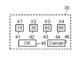
- Fig. 10 is an explanatory diagram illustrating first numerical input fields 41 to 44 in a creation support method according to Modification 2.
- the first UI element 30 includes a plurality of first numerical input fields 41 to 44, a confirmation icon 45, and a cancel icon 46.
- FIG. 11 is an explanatory diagram illustrating an example of a display screen in the creation support method according to the second modification.
- identification notations "X1", “X2", “X3”, and "X4" for identifying the division lines B1 to B4 are displayed at predetermined positions around each of the division lines B1 to B4 (for example, positions below the division lines B1 to B4) on the display screen G6 of the display unit 11.
- the identification notation "X1" indicates the division line B1
- the identification notation "X2" indicates the division line B2
- the identification notation "X3" indicates the division line B3
- the identification notation "X4" indicates the division line B4.
- the multiple first numerical input fields 41-44 correspond one-to-one to the multiple dividing lines B1-B4 that divide the horizontal axis (main axis position) of the curves C1-C4.
- the multiple first numerical input fields 41-44 accept input of numerical values for specifying the positions X1-X4 of the corresponding dividing lines B1-B4. Numerical values can be input into the first numerical input fields 41-44 by inputting data into the input unit 12.
- the identification notations "X1"-"X4" of the corresponding dividing lines B1-B4 are displayed. This makes it easy to understand the correspondence between the first numeric input fields 41-44 and the dividing lines B1-B4.
- the confirmation icon 45 is an icon for confirming the numerical values entered in the first numerical input fields 41 to 44. By selecting the confirmation icon 45 displayed on the display unit 11 through an input operation on the input unit 12, the numerical values entered in the four first numerical input fields 41 to 44 can be confirmed all at once. In FIG. 10, the confirmation icon 45 is formed, for example, by the letter "OK" written in a rectangular black frame.
- the cancel icon 46 is an icon for canceling all the numbers entered in the four first numeric input fields 41 to 44 at once. By selecting the cancel icon 46 displayed on the display unit 11 through an input operation on the input unit 12, it is possible to cancel all the numbers entered in the numeric input fields 41 to 44 at once.
- the cancel icon 46 is formed, for example, by the word "cancel" written within a rectangular black frame.
- a dedicated screen for displaying the first numerical input fields 41 to 44, the confirmation icon 45, and the cancellation icon 46 is displayed on the display unit 11.
- the first numerical input fields 41 to 44, the confirmation icon 45, and the cancellation icon 46 may be displayed on the display unit 11 in place of the selection icons 21 to 23 in the first embodiment.
- the user inputs numerical values into the first numerical input fields 41-44 by performing an input operation on the input unit 12, and selects the confirmation icon 45 to confirm the input.
- the numerical values "15”, “35”, “65”, and “85” are input and confirmed in the first numerical input fields 41-44, respectively.
- the graph generating unit 144 changes the positions X1-X4 of the division lines B1-B4 based on the numerical values input into the first numerical input fields 41-44.
- the graph generating unit 144 regenerates the section shapes of the sections K1-K5 of the curves C1-C4, as in the first embodiment, based on the sections K1-K5 specified by the changed division lines B1-B4.
- the display control unit 143 displays the regenerated curves C1-C4 on the display unit 11.
- the horizontal axis of the curves C1 to C4 and the division positions of the curves C1 to C4 are changed by specifying numerical values. This allows the division positions to be changed with high precision.
- FIG. 12 is an explanatory diagram illustrating second numerical input fields 51 to 55 in a creation support method according to Modification 3.
- the first UI element 30 in the above embodiment further includes a plurality of (five in Fig. 12) second numerical input fields 51 to 55 in addition to the sliders 252g to 252j.
- the second numerical input fields 51-55 correspond one-to-one to the sections K1-K5 of the horizontal axis (main axis position) of the curves C1-C4, and accept numerical inputs that specify the section lengths of the corresponding sections K1-K5. Numerical values can be input into the second numerical input fields 51-55 by inputting data into the input unit 12.
- the second numerical input fields 51-55 are arranged, for example, below the sliders 252g-252j, below the corresponding sections K1-K5.
- the display control unit 143 automatically inputs the numerical values of the interval lengths of the intervals K1-K5 at that time into the second numeric input fields 51-55, respectively, initially.
- a slider e.g., 252h
- the second numeric input fields 52, 53 of the two intervals K2, K3 on both sides of the selected slider 252h are selected.
- FIG. 13 is an explanatory diagram for explaining an example of the operation of the second numeric input field in the creation support method according to the third modification.
- the numerical value in the other of the two selected second numerical input fields 52, 53 e.g., 53
- the sum of the numerical values in the two second numerical input fields 52, 53 on either side of the slider 252h is the same before and after the change in the position of the slider 252h.
- the length of each of the sections K1 to K4 on the horizontal axis of the curves C1 to C4 is changed by specifying a numerical value, so the section lengths can be changed with high precision.
- the second numeric input fields 51-55 are used in combination with the sliders 252a, 252b, 252c, and 252d.
- the second numeric input fields 51-55 may be used in combination with the dividing lines B1-B4 (split bars) of the first modification, instead of the sliders 252a, 252b, 252c, and 252d.
- the second numeric input fields 51-55 may be used alone, without being combined with the sliders 252a, 252b, 252c, and 252d and the dividing lines B1-B4 of the first modification.
- FIG. 14 is an explanatory diagram for explaining the first UI element 30 of the creation support method according to the modified example 4.
- a part of the range of the horizontal axis of the curves C1 to C4 may be divided into a plurality of sections K1 to K5 (five in FIG. 14).
- FIG. 14 shows an example of the display screen G8 of the display unit 11 in the modified example 4.
- the range from near the middle to the right end of the horizontal axis of the curves C1 to C4 is divided into five sections K1 to K5.
- it is combined with sliders 252g to 252j.
- the shape of the cam curve C1 can be changed within a limited range of the cam curve C1 (for example, a range excluding the range in which it is not desired to change the shape of the cam curve C1).
- the above-mentioned shape type is associated with the section shape of each section of the acceleration curve C3.
- a predetermined shape type may also be associated with the section shape of each section of the speed curve C2.
- the speed curve C2 is regenerated so that the section shape of the speed curve in a predetermined section (third predetermined section) among the multiple sections becomes a shape (shape type) that does not change with respect to the horizontal axis (main axis position) of the curve C2.
- the display control unit 143 displays the regenerated speed curve C2 on the display unit 11.
- the display control unit 143 displays the speed curve C2 on the display unit 11 so that it becomes the above-mentioned shape (shape type).
- the fifth modification it is possible to easily create a cam curve C1 having a speed curve C2 in which the section shape of the speed curve C2 in a predetermined section (third predetermined section) of the multiple sections does not change with respect to the spindle position.
- the section shape of the speed curve C2 in a predetermined section (third predetermined section) of the multiple sections have a shape that does not change with respect to the spindle position, it is possible to suppress the slave axis acceleration.
- the second UI element 20 is a radio button type selection icon 21 to 23.
- the second UI element 20 is not limited to a radio button type selection icon.
- the second UI element 20 may be a toggle button type selection icon instead of a radio button type.
- the radio buttons of the selection icons 21 to 23 are replaced with a toggle button for alternatively selecting selected and unselected.
- the selection icon is alternatively selected to be selected and unselected.
- the second UI element 20 may be, for example, a drop-down list type icon. In this case, an icon displaying the "number of divisions" is displayed as the second UI element 20. When the icon is selected, candidates for the number of divisions, such as 5 divisions and 7 divisions, are displayed in a list around the icon (for example, below), and a desired number of divisions is selected from the list.
- the horizontal axis (main axis position) of the curves C1 to C4 is divided into 5 and 7. However, it may be divided into a number of divisions other than 5 and 7 (for example, 3, 9, 11, etc.).
- the creation support method of the first aspect supports the creation of a cam curve (C1) that represents the slave axis position relative to the master axis position.
- the creation support method includes a display control process (step S4), a first reception process (step S6), and a generation process (step S7).
- an axis (horizontal axis) that defines the master axis position in the graph is divided into a plurality of sections (K1 to K5, K11 to K17), and the cam curve (C1), the velocity curve (C2) that represents the slave axis speed relative to the master axis position, and the acceleration curve (C3) that represents the slave axis acceleration relative to the master axis position are displayed on the display unit (11) so as to be continuous at the division positions of the plurality of sections (K1 to K5, K11 to K17), and a first user interface element (30) that receives a first operation for changing the division position is displayed on the display unit (11).
- step S6 a first operation to the first user interface element (30) is received.
- step S7 the division position is changed based on the first operation received in the first reception process (step S6), and the section shapes in the multiple sections (K1 to K5, K11 to K17) of the cam curve (C1), velocity curve (C2), and acceleration curve (C3) displayed on the display unit (11) are regenerated based on the changed division position.
- the acceleration curve (C3) is displayed on the display unit (11) so that the section shape of the acceleration curve (C3) in a first predetermined section (K2, K4, K12, K16) among the multiple sections (K1 to K5, K11 to K17) does not change with respect to the spindle position.
- the acceleration curve (C3) is displayed on the display unit (11) in the display control process (step S4)
- the acceleration curve (C3) is displayed on the display unit (11) in such a way that the section shape of the acceleration curve (C3) in the first predetermined section (K2, K4, K12, K16) of the multiple sections (K1 to K5, K11 to K17) does not change with respect to the spindle position in the initial setting.
- the first reception process (step S6) the division positions of the multiple sections (K1 to K5, K11 to K17) are changed based on the user's operation, and the shape of the acceleration curve (C3) is corrected in the graph generation process (step S7).
- cam curve (C1) By creating the cam curve (C1) in this manner, it is possible to easily (i.e., without performing complicated operations) create a cam curve (C1) in which the section shape of the acceleration curve (C3) in the first predetermined section (K2, K4, K12, K16) of the multiple sections (K1 to K5, K11 to K17) does not change with respect to the spindle position.
- the section shape of the acceleration curve (C3) in the first predetermined section (K2, K4, K12, K16) among the multiple sections (K1-K5, K11-K17) have a shape that does not change with respect to the main axis position, it is possible to suppress the slave axis acceleration throughout the entire range of the cam curve (C1).
- the second aspect of the creation support method is the first aspect, in which the display control process displays the acceleration curve (C3) on the display unit (11) so that the section shape of the acceleration curve (C3) in a second predetermined section (K1, K3, K5, K11, K13, K15, K17) among the multiple sections (K1 to K5, K11 to K17) is a shape that monotonically increases or decreases with respect to the spindle position.
- This configuration makes it easy to create a cam curve (C1) in which the section shape of the acceleration curve (C3) in the second predetermined section (K1, K3, K5, K11, K13, K15, K17) among the multiple sections (K1 to K5, K11 to K17) is a shape that monotonically increases or decreases with respect to the spindle position.
- the creation support method of the third aspect is the second aspect, and in the above display control process, the speed curve (C2) is displayed on the display unit (11) so that the section shape of the speed curve (C2) in a third predetermined section (K14) among the multiple sections (K1 to K5, K11 to K17) is a shape that does not change with respect to the spindle position.
- This configuration makes it easy to create a cam curve (C1) in which the section shape of the speed curve (C2) in the third predetermined section (K14) of the multiple sections (K1 to K5, K11 to K17) is a shape that does not change with respect to the spindle position.
- the slave shaft speed can be suppressed.
- the first user interface element (30) includes sliders (252a to 252f; 252g to 252j) displayed on the display unit (11).
- the sliders (252a to 252f; 252g to 252j) can be displaced along an axis (horizontal axis) that defines the main axis position by an input operation to a specified input unit (12), and correspond to the division positions of a plurality of sections (K1 to K5, K11 to K17).
- a first reception process (step S6)
- a change in the position of the sliders (252a to 252f; 252g to 252j) by an input operation to the specified input unit (12) is accepted.
- the generation process step S7, the positions of the sliders (252a to 252f; 252g to 252j) are changed by inputting operations into a specific input unit (12), thereby changing the corresponding division positions.
- the division position can be intuitively changed by changing the position of the sliders (252a to 252f; 252g to 252j) through input operations on the input unit (12).
- the first user interface element (30) includes split bars (B11 to B16) displayed on the display unit (11).
- the split bars (B11 to B16) can be displaced along an axis (horizontal axis) that defines the main axis position by an input operation to a specified input unit (12), and are displayed so as to be perpendicular to the axis that defines the main axis position at the division positions of the multiple sections (K1 to K5, K11 to K17).
- a change in the position of the split bars (B11 to B16) is accepted by an input operation to the specified input unit (12).
- the position of the split bars (B11 to B16) is changed by an input operation to the specified input unit (12), thereby changing the corresponding division position.
- the position of the split bars (B11 to B16) can be changed by inputting an input operation to the input unit (12), so the split position can be changed intuitively. Since the split lines (B11 to B16) already displayed on the display unit (11) are used as the first user interface element (30), there is no need to display a new component as the first user interface element (30) on the display unit (11).
- the first user interface element (30) is a first numeric input field (41-44) into which a numeric value is input to specify the division position of the multiple sections (K1-K5, K11-K17), or a second numeric input field (51-55) into which a numeric value is input to specify the section length of the multiple sections (K1-K5, K11-K17).
- the division position or section length can be changed by specifying it numerically, so the division position or section length can be changed with high precision.
- the display unit (11) further displays a second user interface element (20) that receives a second operation for setting the number of divisions of the multiple sections (K1 to K5, K11 to K17).
- the creation support method further includes a second reception process (step S2) that receives a second operation on the second user interface element (20).
- the number of divisions into the multiple sections (K1 to K5, K11 to K17) can be changed by a second operation on the second user interface element (20).
- multiple sections (K1 to K5) are set so as to divide a portion of the range of the CAM curve (C1) into multiple sections (K1 to K5).
- the shape of the cam curve (C1) can be changed within a limited range of the cam curve (C1) (for example, a range excluding the range in which it is not desired to change the shape of the cam curve (C1)).
- the program of the ninth aspect causes a computer to execute any one of the creation assistance methods of the first to third aspects.
- This configuration makes it possible to provide a program that records the creation support methods of the first to third aspects.
- a tenth aspect of the creation support device (10) supports the creation of a cam curve (C1) representing a slave axis position relative to a master axis position.
- the creation support device (10) includes a display control unit (143), a first reception processing unit (141), and a generation unit (144).
- the display control unit (143) divides the master axis position in the graph into a plurality of sections (K1 to K5, K11 to K17), and displays the cam curve (C1), the velocity curve (C2) representing the slave axis velocity relative to the master axis position, and the acceleration curve (C3) representing the slave axis acceleration relative to the master axis position on the display unit (11) so as to be continuous at the division positions of the plurality of sections (K1 to K5, K11 to K17), and displays on the display unit (11) a first user interface element (30) that accepts a first operation for changing the division position.
- the first reception processing unit (141) accepts a first operation to the first user interface element (30).
- the generation unit (144) changes the division position based on the first operation received by the first reception processing unit (141), and regenerates the section shapes in the multiple sections (K1 to K5, K11 to K17) of the cam curve (C1), velocity curve (C2), and acceleration curve (C3) displayed on the display unit (11) based on the changed division position.
- the display control unit (143) displays the acceleration curve (C3) on the display unit (11) so that the section shape of the acceleration curve (C3) in a first predetermined section (K2, K4, K12, K16) of the multiple sections (K1 to K5, K11 to K17) does not change with respect to the spindle position.
- This configuration makes it possible to provide a creation support device that achieves the same effects as the creation support method of the first aspect.
- the creation support method, program, and creation support device disclosed herein can support the creation of a cam curve in which the slave axis acceleration is suppressed throughout the entire range of the cam curve without the need for complicated operations, making them useful for a variety of electronic cams.
Landscapes
- Engineering & Computer Science (AREA)
- Human Computer Interaction (AREA)
- Manufacturing & Machinery (AREA)
- Physics & Mathematics (AREA)
- General Physics & Mathematics (AREA)
- Automation & Control Theory (AREA)
- Mechanical Engineering (AREA)
- User Interface Of Digital Computer (AREA)
Priority Applications (2)
| Application Number | Priority Date | Filing Date | Title |
|---|---|---|---|
| JP2025508213A JPWO2024195361A1 (https=) | 2023-03-23 | 2024-02-13 | |
| CN202480010107.6A CN120548513A (zh) | 2023-03-23 | 2024-02-13 | 制作辅助方法、程序以及制作辅助装置 |
Applications Claiming Priority (2)
| Application Number | Priority Date | Filing Date | Title |
|---|---|---|---|
| JP2023-047324 | 2023-03-23 | ||
| JP2023047324 | 2023-03-23 |
Publications (1)
| Publication Number | Publication Date |
|---|---|
| WO2024195361A1 true WO2024195361A1 (ja) | 2024-09-26 |
Family
ID=92841266
Family Applications (1)
| Application Number | Title | Priority Date | Filing Date |
|---|---|---|---|
| PCT/JP2024/004841 Ceased WO2024195361A1 (ja) | 2023-03-23 | 2024-02-13 | 作成支援方法、プログラム、及び、作成支援装置 |
Country Status (3)
| Country | Link |
|---|---|
| JP (1) | JPWO2024195361A1 (https=) |
| CN (1) | CN120548513A (https=) |
| WO (1) | WO2024195361A1 (https=) |
Citations (4)
| Publication number | Priority date | Publication date | Assignee | Title |
|---|---|---|---|---|
| WO2002091090A1 (en) * | 2001-04-27 | 2002-11-14 | Citizen Watch Co., Ltd. | Automatic lathe, and method for controlling the same and device for controlling the same |
| WO2013175615A1 (ja) * | 2012-05-24 | 2013-11-28 | 三菱電機株式会社 | 電子カム制御装置および電子カム曲線生成方法 |
| CN113985805A (zh) * | 2021-10-28 | 2022-01-28 | 福州富昌维控电子科技有限公司 | 一种电子凸轮的生成方法及终端 |
| WO2022118707A1 (ja) * | 2020-12-03 | 2022-06-09 | パナソニックIpマネジメント株式会社 | カム曲線生成装置、カム曲線生成方法、および、プログラム |
-
2024
- 2024-02-13 JP JP2025508213A patent/JPWO2024195361A1/ja active Pending
- 2024-02-13 WO PCT/JP2024/004841 patent/WO2024195361A1/ja not_active Ceased
- 2024-02-13 CN CN202480010107.6A patent/CN120548513A/zh active Pending
Patent Citations (4)
| Publication number | Priority date | Publication date | Assignee | Title |
|---|---|---|---|---|
| WO2002091090A1 (en) * | 2001-04-27 | 2002-11-14 | Citizen Watch Co., Ltd. | Automatic lathe, and method for controlling the same and device for controlling the same |
| WO2013175615A1 (ja) * | 2012-05-24 | 2013-11-28 | 三菱電機株式会社 | 電子カム制御装置および電子カム曲線生成方法 |
| WO2022118707A1 (ja) * | 2020-12-03 | 2022-06-09 | パナソニックIpマネジメント株式会社 | カム曲線生成装置、カム曲線生成方法、および、プログラム |
| CN113985805A (zh) * | 2021-10-28 | 2022-01-28 | 福州富昌维控电子科技有限公司 | 一种电子凸轮的生成方法及终端 |
Also Published As
| Publication number | Publication date |
|---|---|
| CN120548513A (zh) | 2025-08-26 |
| JPWO2024195361A1 (https=) | 2024-09-26 |
Similar Documents
| Publication | Publication Date | Title |
|---|---|---|
| JP5612677B2 (ja) | 加工ユニットの動作を表示し、ユーザ入力から処理データを生成する仮想工作機械 | |
| JP6045716B2 (ja) | プログラム作成装置、プログラム作成方法、およびプログラム | |
| EP3178618B1 (en) | Offline teaching device | |
| TWI498693B (zh) | 多軸控制系統設定、調整功能支援裝置 | |
| CN106843141B (zh) | 数值控制装置 | |
| US20090299526A1 (en) | Device and method for processing a robot control program | |
| JP5990662B2 (ja) | 加工プログラム編集支援装置 | |
| JP2002254273A (ja) | 切削工機の制御装置、切削工機及びその切削方法 | |
| WO2024195361A1 (ja) | 作成支援方法、プログラム、及び、作成支援装置 | |
| JPH0363756A (ja) | 文書編集装置 | |
| TWI578129B (zh) | 定位控制裝置之同步控制設定方法及定位控制裝置之控制設定裝置 | |
| JP2015079491A (ja) | 加工データ演算装置および加工データ演算プログラム | |
| JP6532094B1 (ja) | 表示処理装置、表示処理方法、及びプログラム | |
| JP6339602B2 (ja) | サイクルタイムが比較可能な波形表示装置 | |
| US11360454B2 (en) | Ladder display device for circuit generation using touch panel | |
| JP2012088791A (ja) | 情報処理装置、情報処理方法、およびプログラム | |
| JP7772829B2 (ja) | プログラム教示支援装置 | |
| US12001186B2 (en) | Information processing method, information processing apparatus, production system and article manufacturing method | |
| JP5962696B2 (ja) | 図形表示装置およびプログラム | |
| JPH0272413A (ja) | 数値制御装置用プログラム作成装置 | |
| KR102035464B1 (ko) | 프로그램 생성 장치 및 프로그램 생성 장치에 있어서의 프로그램 생성 방법 | |
| JP2006344041A (ja) | 工具軌跡描画方法及び装置 | |
| JP2025056824A (ja) | プログラム生成装置及びプログラム生成プログラム | |
| JPS62277287A (ja) | ロボットのオフライン・プログラミング装置 | |
| JPH0715642B2 (ja) | 軌跡表示画面における移動スケール表示方式 |
Legal Events
| Date | Code | Title | Description |
|---|---|---|---|
| 121 | Ep: the epo has been informed by wipo that ep was designated in this application |
Ref document number: 24774507 Country of ref document: EP Kind code of ref document: A1 |
|
| WWE | Wipo information: entry into national phase |
Ref document number: 202480010107.6 Country of ref document: CN |
|
| WWP | Wipo information: published in national office |
Ref document number: 202480010107.6 Country of ref document: CN |
|
| ENP | Entry into the national phase |
Ref document number: 2025508213 Country of ref document: JP Kind code of ref document: A |
|
| WWE | Wipo information: entry into national phase |
Ref document number: 2025508213 Country of ref document: JP |
|
| NENP | Non-entry into the national phase |
Ref country code: DE |
|
| 122 | Ep: pct application non-entry in european phase |
Ref document number: 24774507 Country of ref document: EP Kind code of ref document: A1 |