WO2024190851A1 - 印刷装置 - Google Patents
印刷装置 Download PDFInfo
- Publication number
- WO2024190851A1 WO2024190851A1 PCT/JP2024/009914 JP2024009914W WO2024190851A1 WO 2024190851 A1 WO2024190851 A1 WO 2024190851A1 JP 2024009914 W JP2024009914 W JP 2024009914W WO 2024190851 A1 WO2024190851 A1 WO 2024190851A1
- Authority
- WO
- WIPO (PCT)
- Prior art keywords
- wiping
- wiping member
- nozzle surface
- nozzle
- unit
- Prior art date
- Legal status (The legal status is an assumption and is not a legal conclusion. Google has not performed a legal analysis and makes no representation as to the accuracy of the status listed.)
- Ceased
Links
Images





Classifications
-
- B—PERFORMING OPERATIONS; TRANSPORTING
- B41—PRINTING; LINING MACHINES; TYPEWRITERS; STAMPS
- B41J—TYPEWRITERS; SELECTIVE PRINTING MECHANISMS, i.e. MECHANISMS PRINTING OTHERWISE THAN FROM A FORME; CORRECTION OF TYPOGRAPHICAL ERRORS
- B41J2/00—Typewriters or selective printing mechanisms characterised by the printing or marking process for which they are designed
- B41J2/005—Typewriters or selective printing mechanisms characterised by the printing or marking process for which they are designed characterised by bringing liquid or particles selectively into contact with a printing material
- B41J2/01—Ink jet
- B41J2/135—Nozzles
- B41J2/165—Prevention or detection of nozzle clogging, e.g. cleaning, capping or moistening for nozzles
Definitions
- the present invention relates to a printing device.
- a wiper unit is provided that wipes off ink adhering to the nozzle surface of the ejection head (see, for example, Patent Document 1).
- the present invention has been made in consideration of the above, and aims to provide a printing device that can properly remove ink from the nozzle surface.
- the printing device comprises an ejection head having a nozzle surface on which a number of nozzles for ejecting ink are formed in a row at predetermined intervals, a wiping unit for wiping the nozzle surface, and a drive unit for moving the nozzle surface and the wiping unit relatively, the ejection head ejects the ink onto a printing target placed in a printing area while moving in a preset main scanning direction, and the wiping unit has two wiping members of different hardness arranged side by side in the direction in which the nozzle surface and the wiping unit move relatively when wiping the nozzle surface, and a holding unit for holding the two wiping members together.
- ink can be properly wiped off the nozzle surface.
- FIG. 9 is a diagram showing an example of a wiping operation by the wiper unit.
- FIG. 10 is a diagram showing an example of a wiping operation by the wiper unit.
- FIG. 11 is a diagram showing an example of a wiping operation by the wiper unit.
- FIG. 12 is a diagram showing an example of a wiping operation by the wiper unit.
- FIG. 13 is a diagram showing another example of the ejection head.
- FIG. 14 is a diagram showing an example of wiping the ejection head shown in FIG. 13 by the wiper unit.
- FIG. 15 is a diagram showing an example of wiping the ejection head shown in FIG. 13 by the wiper unit.
- FIG. 16 is a diagram showing an example of wiping the ejection head shown in FIG. 13 by the wiper unit.
- FIG. 17 is a diagram showing an example of a case where wiping is performed on the ejection head shown in FIG. 13 by a wiper unit having another configuration.
- FIG. 18 is a diagram showing an example of a case where wiping is performed on the ejection head shown in FIG. 13 by a wiper unit having another configuration.
- FIG. 19 is a diagram showing an example of a case where wiping is performed on the ejection head shown in FIG. 13 by a wiper unit having another configuration.
- FIG. 20 is a diagram showing an example of a case where wiping is performed on the ejection head shown in FIG. 13 by a wiper unit having another configuration.
- FIG. 21 is a diagram showing an example of a case where wiping is performed on the ejection head shown in FIG. 13 by a wiper unit having another configuration.
- FIG. 22 is a diagram showing an example of a printing apparatus according to another configuration.
- FIG. 1 is a perspective view showing a schematic example of a printing device according to this embodiment.
- the printing device 100 shown in FIG. 1 is an inkjet printer that performs printing on media M using an inkjet method.
- the printing device 100 includes a carriage 10, a guide mechanism 20, and a wiper unit 30.
- the ejection head 11 ejects ink toward the medium M in the printing area PA.
- the medium M is placed on the platen 16 in the printing area PA.
- the ejection head 11 has a nozzle surface 13.
- the nozzle surface 13 is, for example, flat, and has nozzles 14 formed thereon to eject ink.
- the nozzle surface 13 is treated to be water-repellent in order to ensure a meniscus of the ink in the nozzles 14.
- the nozzles 14 are arranged, for example, in a line in a predetermined direction. Examples of the ink include ultraviolet-curable ink.
- Types of ultraviolet-curable ink include white ink, colored inks such as cyan (C), magenta (M), yellow (Y) and black (K), and transparent inks, depending on the color of the image to be formed on the medium M. Even in the case of inks other than ultraviolet-curable inks, inks that are prone to adhere solid matter to the nozzle surface due to drying and hardening of the ink, such as latex ink, can also be used as appropriate.
- the ink that can be used can be one in which the ink droplets adhering to the nozzle surface 13 solidify at least during the longest non-ejection time.
- the light irradiation device 12 irradiates ultraviolet light onto the ultraviolet curable ink ejected onto the medium M.
- the light irradiation device 12 is composed of, for example, an LED module capable of irradiating ultraviolet light.
- the light irradiation device 12 moves back and forth in the main scanning direction together with the ejection head 11 as the carriage 10 moves.
- the wiper unit 30 is provided in the maintenance area MA of the printing device 100.
- the maintenance area MA is disposed outside the printing area PA in the Y direction.
- the wiper unit 30 wipes the nozzle surface 13 of the ejection head 11.
- the wiper unit 30 has a wiping section 31 and a second drive mechanism 32.
- the wiping section 31 is disposed so as to face the nozzle surface 13 of the ejection head 11 at at least one location on an extension line in the Y direction, which is the main scanning direction, for example, at one predetermined position on the +Y side of the platen 16 in this embodiment.
- the second wiping member 34 has a lower hardness than the first wiping member 33.
- the first wiping member 33 has a higher hardness than the second wiping member 34.
- hardness can be defined as the resistance to deformation due to a force in the wiping direction, for example.
- the first wiping member 33 is formed to have a Young's modulus in the range of 400 MPa to 800 MPa, for example.
- the second wiping member 34 is formed to have a Young's modulus in the range of 0.5 MPa to 100 MPa, for example.
- the first wiping member 33 is formed using a plastic material such as polypropylene.
- the second wiping member 34 is formed using a rubber material such as ethylene propylene rubber, for example.
- the first wiping member 33 and the second wiping member 34 are arranged side by side in the wiping direction.
- the first wiping member 33 is arranged on the +X side of the wiping direction.
- the second wiping member 34 is arranged on the -X side of the wiping direction.
- the first wiping member 33 has a thickness (dimension in the wiping direction) of, for example, about 0.35 mm.
- the first wiping member 33 has a flat top surface 33f.
- the first wiping member 33 has corners 33p and 33q on both sides of the top surface 33f in the wiping direction. By having the corners 33p and 33q, when the wiping section 31 moves in the wiping direction, the first wiping member 33 can wipe the nozzle surface 13 with its edges.
- the first wiping member 33 may be formed so that the corner 33q is higher in the Z direction than the corner 33p. In this case, the top surface 33f is configured to be inclined upward from the corner 33p to the corner 33q.
- the dimension in the Y direction of the first wiping member 33 is similar to or larger than the dimension in the Y direction of the ejection head 11.
- the dimension in the Y direction of the second wiping member 34 is similar to or larger than the dimension in the Y direction of the nozzle surface 13 of the ejection head 11. Therefore, the first wiping member 33 and the second wiping member 34 can wipe the entire area in the Y direction of the nozzle surface 13 of the ejection head 11.
- the second wiping member 34 protrudes from the holding portion 35 toward the nozzle surface 13 further than the first wiping member 33. Therefore, when the wiping portion 31 is raised toward the nozzle surface 13, the second wiping member 34 comes into contact with the nozzle surface 13 first. Furthermore, when the wiping portion 31 is raised until the first wiping member 33 comes into contact with the nozzle surface 13, the second wiping member 34 becomes elastically deformed in the vertical direction.
- the holding portion 35 holds the first wiping member 33 and the second wiping member 34 together.
- the holding portion 35 holds the first wiping member 33 and the second wiping member 34 in a detachable manner.
- the second drive mechanism 32 moves the wiping unit 31 back and forth in the X direction (sub-scanning direction).
- the X direction (sub-scanning direction) which is the movement direction of the wiping unit 31, is the wiping direction of the wiping unit 31 in this embodiment.
- the wiping direction may be a reciprocating direction in the X direction, or a one-way direction.
- the second drive mechanism 32 also moves the wiping unit 31 back and forth in the Z direction (lifting direction). By moving the wiping unit 31 in the Z direction, the first wiping member 33 and the second wiping member 34 can be brought into contact with the nozzle surface 13 and released from contact. By moving the wiping unit 31 in the X direction with the first wiping member 33 and the second wiping member 34 in contact with the nozzle surface 13, the wiping unit 31 can wipe the nozzle surface 13.
- FIGs 4 to 12 are diagrams showing an example of the wiping operation by the wiper unit 30.
- the ejection head 11 is moved above the wiper unit 30. From this state, as shown in Figure 4, the second drive mechanism 32 raises the wiping section 31 toward the nozzle surface 13 of the ejection head 11. As the wiping section 31 rises, the second wiping member 34 first comes into contact with the nozzle surface 13. As the wiping section 31 is further raised, the first wiping member 33 comes into contact with the nozzle surface 13, and the second wiping member 34 becomes elastically deformed.
- the second drive mechanism 32 moves the wiping section 31 in the wiping direction.
- the wiping section 31 wipes the nozzle surface 13 with the first wiping member 33 positioned in front of the wiping direction and the second wiping member 34 positioned in the rear of the wiping direction.
- the corners 33p and 34p of the first wiping member 33 and the second wiping member 34 are in contact with the nozzle surface 13 with their upper ends bent backward. Therefore, the first wiping member 33 and the second wiping member 34 can wipe the nozzle surface 13 with their edges being effective.
- the second wiping member 34 has a lower hardness than the first wiping member 33, so it bends backward more.
- the first wiping member 33 which is made of a plastic material, can scrape off the ink Q1 that has adhered to the nozzle surface 13 and dried or solidified.
- the second wiping member 34 which is made of a rubber material, can scrape off the ink Q2 in droplets or mist form adhering to the nozzle surface 13.
- the first wiping member 33 is capable of removing dried or solidified ink Q1, but may not be able to fully remove the ink Q2 in droplets or mist form that is not dried or solidified. In this case, some of the ink Q2 remains on the nozzle surface 13.
- a second wiping member 34 that is lower in hardness than the first wiping member 33 is provided, and therefore, as shown in FIG. 10, the ink Q2 remaining on the nozzle surface 13 can be removed by the second wiping member 34. Therefore, by moving the wiping section 31 once in the wiping direction, both the dried or solidified ink Q1 and the ink Q2 in droplet or mist form can be appropriately removed.
- the wiping section 31 may be moved so that the second wiping member 34 is in front of the wiping direction, as shown in Figures 11 and 12. In this case, the ink Q2 can be appropriately removed by the second wiping member 34.
- the printing device 100 includes an ejection head 11 having a nozzle surface 13 on which a plurality of nozzles 14 for ejecting ink are formed in a row at predetermined intervals, a wiping unit 31 for wiping the nozzle surface 13, and a drive unit 40 for moving the nozzle surface 13 and the wiping unit 31 relatively, the ejection head 11 ejects ink onto a medium M placed in a printing area while moving in a preset main scanning direction, and the wiping unit 31 includes a first wiping member 33 and a second wiping member 34 of different hardness that are arranged side by side in the direction in which the nozzle surface 13 and the wiping unit 31 move relatively when wiping the nozzle surface 13, and a holding unit 35 that holds the first wiping member 33 and the second wiping member 34 together.
- the first wiping member 33 and the second wiping member 34 which have different hardnesses, are held together in the wiping section 31. Therefore, when the first wiping member 33 and the second wiping member 34 are brought into contact with the nozzle surface 13 and the wiping section 31 is moved in the wiping direction, both dried or solidified ink and mist or droplet-like ink can be appropriately removed in a single movement.
- the drive unit 40 has a first drive mechanism 22 that moves the ejection head 11 in a preset main scanning direction, and a second drive mechanism 32 that moves the wiping unit 31 relative to the nozzle surface 13.
- the first wiping member 33 is disposed on one side by the drive unit 40 in the direction in which the nozzle surface 13 and the wiping unit 31 move relative to each other when wiping the nozzle surface 13.
- the second wiping member 34 is disposed on the other side in the same direction and has a lower hardness than the first wiping member 33.
- the second wiping member 34 protrudes from the holding portion toward the nozzle surface 13 further than the first wiping member 33. With this configuration, the second wiping member 34 can be elastically deformed while the first wiping member 33 is in contact with the nozzle surface 13.
- the second drive mechanism 32 can move the wiping section 31 in an elevation direction perpendicular to the nozzle surface 13. With this configuration, the first wiping member 33 and the second wiping member 34 can be appropriately brought into contact with the nozzle surface 13 by driving the second drive mechanism 32.
- the second drive mechanism 32 can move the wiping section 31 in the lifting direction to position the first wiping member 33 and the second wiping member 34 in contact with the nozzle surface 13 while the second wiping member 34 is elastically deformed.
- the nozzle surface 13 can be wiped by driving the second drive mechanism 32 while the first wiping member 33 and the second wiping member 34 are in appropriate contact with the nozzle surface 13.
- the wiping unit 31 is disposed so as to face the nozzle surface 13 of the ejection head 11 at at least one predetermined position on an extension line of the main scanning direction.
- the nozzle surface 13 can be made to face the wiping unit 31 by moving the ejection head 11 in the extension direction of the main scanning direction.
- the ink that can be used is, for example, an ink whose droplets adhering to the nozzle surface 13 solidify at least during the longest non-ejection time. This allows the wiping unit 31 to properly wipe off the ink if the ink solidifies during movement in the main scanning direction after the ejection head 11 ejects ink.
- the first wiping member 33 is formed using a non-absorbent material
- the second wiping member 34 is formed using an absorbent elastic material.
- the first wiping member 33 and the second wiping member 34 can each be formed to a hardness that allows ink to be appropriately removed. For example, solidified ink can be wiped away by the first wiping member 33, and liquid ink can be wiped away by the second wiping member 34.
- the printing device 100 includes an ejection head 11 having a nozzle surface 13 on which nozzles 14 for ejecting ink are formed, and a wiper unit for wiping the nozzle surface 13 of the ejection head 11, with the wiper unit 30 described above being used as the wiper unit.
- the wiper unit 30 that can properly remove both dried or solidified ink and mist or droplet-like ink in a single movement, it is possible to prevent the nozzle surface 13 from being wiped more than necessary by a wiping member with high hardness, and to prevent deterioration of the water-repellent finish of the nozzle surface 13. This makes it possible to extend the life of the ejection head 11.
- the ink used in the printing device 100 is ultraviolet-curable ink.
- the ejection head 11 that ejects ultraviolet-curable ink, dried or cured ink and mist or droplet-like ink tend to be mixed on the nozzle surface 13.
- a single movement of the wiping unit 31 can properly remove both dried or solidified ink and mist or droplet-like ink.
- FIG. 13 is a diagram showing another example of an ejection head.
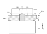
- the ejection head 11A has a nozzle plate 15 disposed on a nozzle surface 13.
- the nozzle plate 15 is formed so as to surround a nozzle region 13R of the nozzle surface 13 in which a plurality of nozzles 14 are formed. For this reason, a step is formed on the nozzle surface 13 between the nozzle region 13R and the surface 15R of the nozzle plate 15.
- the step is formed, for example, by the thickness of the nozzle plate 15.
- FIGS. 14 to 16 are diagrams showing an example of wiping the ejection head 11A shown in FIG. 13 with the wiper unit 30.
- the second drive mechanism 32 also raises the wiping section 31 when a step is formed on the nozzle surface 13.
- the second wiping member 34 first comes into contact with the surface 15R of the nozzle plate 15, as shown in FIG. 14.
- the second drive mechanism 32 further raises the wiping section 31, so that the first wiping member 33 comes into contact with the surface 15R of the nozzle plate 15, as shown in FIG. 15. Also, a portion of the second wiping member 34 elastically deforms and enters the step portion, coming into contact with the nozzle region 13R of the nozzle surface 13.
- the second drive mechanism 32 moves the wiping section 31 in the wiping direction, so that the first wiping member 33 wipes the surface 15R of the nozzle plate 15, and a part of the second wiping member 34 that has entered the stepped portion wipes the nozzle region 13R, as shown in FIG. 16.
- This makes it possible to properly remove ink adhering to the nozzle region 13R of the nozzle surface 13 and the surface 15R of the nozzle plate 15 for ejection heads 11A that have steps in the nozzle surface 13.
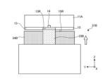
- FIGS. 17 and 18 are diagrams showing an example of wiping the ejection head 11A shown in FIG. 13 with a wiper unit 30A having a different configuration.
- the wiper unit of this example is configured such that the dimension in the Y direction (width direction) of the second wiping member 34A provided in the wiping section 31A is approximately equal to the dimension in the Y direction of the nozzle region 13R.
- the first wiping member 33A has the same configuration as the first wiping member 33 of the wiping section 31 described above.
- the second drive mechanism 32 When wiping with such a wiper unit 30A, the second drive mechanism 32 lifts the wiping section 31A. As the wiping section 31A lifts, the second wiping member 34A first enters the step portion of the nozzle surface 13 and comes into contact with the nozzle region 13R of the nozzle surface 13, as shown in FIG. 17. From this state, the second drive mechanism 32 further lifts the wiping section 31, so that the first wiping member 33 comes into contact with the surface 15R of the nozzle plate 15, as shown in FIG. 18. The second wiping member 34 elastically deforms when it enters the step portion and is in contact with the nozzle region 13R.
- the second drive mechanism 32 moves the wiping section 31A in the wiping direction, causing the first wiping member 33A to wipe the surface 15R of the nozzle plate 15, and the second wiping member 34A, which has entered the stepped portion, to wipe the nozzle region 13R.
- This allows the ink adhering to the nozzle region 13R of the nozzle surface 13 and the surface 15R of the nozzle plate 15 to be properly removed for ejection heads 11A that have a stepped nozzle surface 13.
- FIGS. 19 to 21 are diagrams showing an example of wiping the ejection head 11A shown in FIG. 13 with a wiper unit 30B having a different configuration.
- the wiper unit of this example is configured such that the dimension in the Y direction (width direction) of the first wiping member 33B provided in the wiping section 31B is approximately equal to the dimension in the Y direction of the nozzle region 13R.
- the second wiping member 34B has the same configuration as the second wiping member 34 of the wiping section 31 described above.
- the second drive mechanism 32 When wiping with such a wiper unit, the second drive mechanism 32 lifts the wiping portion 31B. As the wiping portion 31B lifts, the first wiping member 33B enters the step portion of the nozzle surface 13, as shown in FIG. 20. From this state, the second drive mechanism further lifts the wiping portion 31B, so that the second wiping member 34B comes into contact with the surface 15R of the nozzle plate 15. Furthermore, as the wiping portion 31B is further lifted, the first wiping member 33B comes into contact with the nozzle region 13R of the nozzle surface 13, as shown in FIG. 20. Furthermore, the second wiping member 34B elastically deforms while in contact with the surface 15R of the nozzle plate 15.
- the second drive mechanism moves the wiping section 31B in the wiping direction, so that, as shown in FIG. 21, the first wiping member 33B wipes the nozzle region 13R of the nozzle surface 13 at the step portion, and the second wiping member 34B wipes the surface 15R of the nozzle plate 15.
- a plastic material is used as the first wiping member and a rubber material is used as the second wiping member, but this configuration is not limiting.
- a porous material such as a sponge may be used as the second wiping member instead of a rubber material.
- the wiper unit may be configured to supply cleaning liquid to the first wiping member and the second wiping member as needed to increase the cleaning efficiency of wiping by the wiper unit.
- the second drive mechanism 32 which is the drive unit 40, moves the wiping unit 31 in the lifting direction by raising and lowering the wiping unit 31, but the present invention is not limited to this configuration.
- the first drive mechanism 22, which is the drive unit 40 may be capable of moving the ejection head 11 in the lifting direction perpendicular to the nozzle surface 13.
- the first drive mechanism 22 may be configured to be capable of positioning the nozzle surface 13 in a position where it contacts the first wiping member 33 and the second wiping member 34 with the second wiping member 34 elastically deformed by moving the ejection head 11 in the lifting direction. This allows the first wiping member 33 and the second wiping member 34 to be appropriately brought into contact with the nozzle surface 13 by driving the first drive mechanism 22.
- FIG. 22 is a diagram showing an example of a printing device 100C with a different configuration.
- the wiper unit 30 is arranged on the +Y side of the platen 16, but the configuration is not limited to this.
- the wiper unit 30 may be arranged on both the +Y side and the -Y side of the platen 16.
- the wiping section 31 is arranged so that the nozzle surface 13 of the ejection head 11 faces the nozzle surface 13 at two predetermined positions on an extension of the Y direction, which is the main scanning direction, that is, on the +Y side and the -Y side of the platen 16.
Landscapes
- Ink Jet (AREA)
Abstract
Description
Claims (12)
- インクを噴射するノズルが所定の間隔で複数連なって形成されているノズル面を有する噴射ヘッドと、
前記ノズル面を払拭する払拭部と、
前記ノズル面と前記払拭部とを相対的に移動させる駆動部と
を備え、
前記噴射ヘッドは、予め設定された主走査方向に移動しつつ印刷領域に載置される印刷対象に前記インクを噴射し、
前記払拭部は、前記ノズル面の払拭時に該ノズル面と前記払拭部とが相対的に移動する方向に並んで配置される2つの異なる硬度の払拭部材と、2つの前記払拭部材を一体で保持する保持部とを有する
印刷装置。 - 前記駆動部は、
前記噴射ヘッドを予め設定された前記主走査方向に移動させる第1駆動機構と、
前記払拭部を前記ノズル面に対して相対的に移動させる第2駆動機構とを有する
請求項1に記載の印刷装置。 - 2つの前記払拭部材は、前記ノズル面の払拭時に前記ノズル面と前記払拭部とが相対的に移動する方向において、前記駆動部によりその一方側に配置される第1払拭部材と、同方向における他方側に配置され、前記第1払拭部材よりも硬度が低い第2払拭部材とを有する
請求項1に記載の印刷装置。 - 前記第2払拭部材は、前記第1払拭部材よりも前記保持部から前記ノズル面側に突出している
請求項3に記載の印刷装置。 - 前記駆動部は、前記ノズル面に直交する昇降方向に前記払拭部を移動可能である
請求項3に記載の印刷装置。 - 前記駆動部は、前記ノズル面に直交する昇降方向に前記噴射ヘッドを移動可能であり、前記昇降方向に前記噴射ヘッドを移動させることで、前記第2払拭部材を弾性変形させた状態で前記第1払拭部材及び前記第2払拭部材と接触する位置に前記ノズル面を配置可能である
請求項3に記載の印刷装置。 - 前記駆動部は、前記昇降方向に前記払拭部を移動させて、前記第2払拭部材を弾性変形させた状態で前記第1払拭部材及び前記第2払拭部材を前記ノズル面に接触する位置に配置可能である
請求項5または請求項6に記載の印刷装置。 - 前記払拭部は、前記主走査方向の延長線上の少なくとも1ヶ所の所定の位置において、前記噴射ヘッドの前記ノズル面が対向するように配置される
請求項1に記載の印刷装置。 - 前記噴射ヘッドが前記主走査方向において最後に前記インクを噴射してから前記払拭部に対向する位置に到達するまでに要する最長時間を最長無噴射時間とし、
前記インクは、前記ノズル面に付着した前記インクの液滴が少なくとも前記最長無噴射時間中に固形化するインクである
請求項1に記載の印刷装置。 - 前記第1払拭部材は、ヤング率が400MPa~800MPaであるプラスチックまたは樹脂性材料を用いて形成され、
前記第2払拭部材は、ヤング率が0.5MPa~100MPaである弾性材料を用いて形成される
請求項3に記載の印刷装置。 - 前記第1払拭部材は、非吸水性材料を用いて形成され、
前記第2払拭部材は、吸水性弾性材料を用いて形成される
請求項3に記載の印刷装置。 - 前記噴射ヘッドは、前記ノズル面のうち前記ノズルが形成されたノズル領域を囲うように配置されるノズルプレートを更に有し、
前記ノズル面が下に向けられたときの、前記ノズル面と前記ノズルプレートの下面との間には、前記ノズルプレートの厚さ分の段差が形成される
請求項1に記載の印刷装置。
Priority Applications (1)
| Application Number | Priority Date | Filing Date | Title |
|---|---|---|---|
| CN202480016422.XA CN120813482A (zh) | 2023-03-15 | 2024-03-14 | 印刷装置 |
Applications Claiming Priority (2)
| Application Number | Priority Date | Filing Date | Title |
|---|---|---|---|
| JP2023041359A JP2024131229A (ja) | 2023-03-15 | 2023-03-15 | 印刷装置 |
| JP2023-041359 | 2023-03-15 |
Publications (1)
| Publication Number | Publication Date |
|---|---|
| WO2024190851A1 true WO2024190851A1 (ja) | 2024-09-19 |
Family
ID=92755322
Family Applications (1)
| Application Number | Title | Priority Date | Filing Date |
|---|---|---|---|
| PCT/JP2024/009914 Ceased WO2024190851A1 (ja) | 2023-03-15 | 2024-03-14 | 印刷装置 |
Country Status (3)
| Country | Link |
|---|---|
| JP (1) | JP2024131229A (ja) |
| CN (1) | CN120813482A (ja) |
| WO (1) | WO2024190851A1 (ja) |
Citations (8)
| Publication number | Priority date | Publication date | Assignee | Title |
|---|---|---|---|---|
| JP2000318171A (ja) * | 1999-05-07 | 2000-11-21 | Canon Inc | クリーニング方法、および、それが使用されるインクジェット記録装置のクリーニング装置 |
| JP2003246074A (ja) * | 2002-02-25 | 2003-09-02 | Konica Corp | インクジェット記録装置及びインクジェット記録方法 |
| JP2004322541A (ja) * | 2003-04-25 | 2004-11-18 | Seiko Epson Corp | 液体噴射装置 |
| JP2005067028A (ja) * | 2003-08-25 | 2005-03-17 | Ricoh Co Ltd | ヘッドクリーニング装置及び画像形成装置 |
| JP2011051209A (ja) * | 2009-09-01 | 2011-03-17 | Sharp Corp | 液滴吐出装置 |
| JP2014087991A (ja) * | 2012-10-31 | 2014-05-15 | Mimaki Engineering Co Ltd | インクジェット記録装置 |
| JP2015085618A (ja) * | 2013-10-31 | 2015-05-07 | 株式会社ミマキエンジニアリング | インクジェット記録装置 |
| JP2017209939A (ja) * | 2016-05-27 | 2017-11-30 | キヤノン株式会社 | 記録素子基板、液体吐出ヘッドおよび液体吐出装置 |
-
2023
- 2023-03-15 JP JP2023041359A patent/JP2024131229A/ja active Pending
-
2024
- 2024-03-14 CN CN202480016422.XA patent/CN120813482A/zh active Pending
- 2024-03-14 WO PCT/JP2024/009914 patent/WO2024190851A1/ja not_active Ceased
Patent Citations (8)
| Publication number | Priority date | Publication date | Assignee | Title |
|---|---|---|---|---|
| JP2000318171A (ja) * | 1999-05-07 | 2000-11-21 | Canon Inc | クリーニング方法、および、それが使用されるインクジェット記録装置のクリーニング装置 |
| JP2003246074A (ja) * | 2002-02-25 | 2003-09-02 | Konica Corp | インクジェット記録装置及びインクジェット記録方法 |
| JP2004322541A (ja) * | 2003-04-25 | 2004-11-18 | Seiko Epson Corp | 液体噴射装置 |
| JP2005067028A (ja) * | 2003-08-25 | 2005-03-17 | Ricoh Co Ltd | ヘッドクリーニング装置及び画像形成装置 |
| JP2011051209A (ja) * | 2009-09-01 | 2011-03-17 | Sharp Corp | 液滴吐出装置 |
| JP2014087991A (ja) * | 2012-10-31 | 2014-05-15 | Mimaki Engineering Co Ltd | インクジェット記録装置 |
| JP2015085618A (ja) * | 2013-10-31 | 2015-05-07 | 株式会社ミマキエンジニアリング | インクジェット記録装置 |
| JP2017209939A (ja) * | 2016-05-27 | 2017-11-30 | キヤノン株式会社 | 記録素子基板、液体吐出ヘッドおよび液体吐出装置 |
Also Published As
| Publication number | Publication date |
|---|---|
| CN120813482A (zh) | 2025-10-17 |
| JP2024131229A (ja) | 2024-09-30 |
Similar Documents
| Publication | Publication Date | Title |
|---|---|---|
| US8511793B2 (en) | Ejection surface cleaning apparatus, liquid ejection apparatus and ejection surface cleaning method | |
| JP4241795B2 (ja) | 液体噴射装置 | |
| JP4998243B2 (ja) | 液体吐出装置 | |
| US7926904B2 (en) | Inkjet recording apparatus and cleaning method | |
| WO2014069494A1 (ja) | インクジェット記録装置 | |
| US7758151B2 (en) | Wiper device and liquid ejection apparatus | |
| JP7628672B2 (ja) | インクジェットプリンタ | |
| CN103101309A (zh) | 维护装置以及液滴喷出装置 | |
| US9421778B2 (en) | Liquid discharge apparatus | |
| JP4501434B2 (ja) | インクジェットプリンタ | |
| JPH1120187A (ja) | インクジェット記録装置 | |
| JP5336787B2 (ja) | プリンタ装置およびプリンタヘッドのメンテナンス方法 | |
| JP2024131229A (ja) | 印刷装置 | |
| JP2005040975A (ja) | 液体噴射ヘッドのワイピング装置および液体噴射装置 | |
| JP5740912B2 (ja) | 液体噴射装置及び液体噴射装置の制御方法 | |
| JP2004230640A (ja) | インクジェットプリンタ | |
| JP4501435B2 (ja) | インクジェットプリンタ | |
| JP2009160786A (ja) | 液滴吐出装置 | |
| JP2016074176A (ja) | インクジェットヘッドおよびインクジェットプリンター | |
| JP7170492B2 (ja) | インクジェットプリンタ、インクジェットプリンタ印刷方法 | |
| CN108297551A (zh) | 头部清洁机构和具有该头部清洁机构的喷墨记录装置 | |
| JP4218390B2 (ja) | インクジェットプリンタ | |
| JP2024164629A (ja) | 印刷装置 | |
| JP5401687B2 (ja) | ワイピング手段、及びインクジェットプリンタ | |
| WO2024237247A1 (ja) | インクジェットプリンタ及び印刷装置 |
Legal Events
| Date | Code | Title | Description |
|---|---|---|---|
| 121 | Ep: the epo has been informed by wipo that ep was designated in this application |
Ref document number: 24770954 Country of ref document: EP Kind code of ref document: A1 |
|
| WWE | Wipo information: entry into national phase |
Ref document number: 202480016422.X Country of ref document: CN |
|
| NENP | Non-entry into the national phase |
Ref country code: DE |
|
| WWP | Wipo information: published in national office |
Ref document number: 202480016422.X Country of ref document: CN |
|
| 122 | Ep: pct application non-entry in european phase |
Ref document number: 24770954 Country of ref document: EP Kind code of ref document: A1 |