WO2024190359A1 - 配線部材 - Google Patents
配線部材 Download PDFInfo
- Publication number
- WO2024190359A1 WO2024190359A1 PCT/JP2024/006501 JP2024006501W WO2024190359A1 WO 2024190359 A1 WO2024190359 A1 WO 2024190359A1 JP 2024006501 W JP2024006501 W JP 2024006501W WO 2024190359 A1 WO2024190359 A1 WO 2024190359A1
- Authority
- WO
- WIPO (PCT)
- Prior art keywords
- wiring
- linear transmission
- bare
- intersection
- intersection portion
- Prior art date
- Legal status (The legal status is an assumption and is not a legal conclusion. Google has not performed a legal analysis and makes no representation as to the accuracy of the status listed.)
- Pending
Links
Images


Classifications
-
- H—ELECTRICITY
- H01—ELECTRIC ELEMENTS
- H01B—CABLES; CONDUCTORS; INSULATORS; SELECTION OF MATERIALS FOR THEIR CONDUCTIVE, INSULATING OR DIELECTRIC PROPERTIES
- H01B7/00—Insulated conductors or cables characterised by their form
-
- H—ELECTRICITY
- H01—ELECTRIC ELEMENTS
- H01B—CABLES; CONDUCTORS; INSULATORS; SELECTION OF MATERIALS FOR THEIR CONDUCTIVE, INSULATING OR DIELECTRIC PROPERTIES
- H01B7/00—Insulated conductors or cables characterised by their form
- H01B7/08—Flat or ribbon cables
-
- H—ELECTRICITY
- H02—GENERATION; CONVERSION OR DISTRIBUTION OF ELECTRIC POWER
- H02G—INSTALLATION OF ELECTRIC CABLES OR LINES, OR OF COMBINED OPTICAL AND ELECTRIC CABLES OR LINES
- H02G3/00—Installations of electric cables or lines or protective tubing therefor in or on buildings, equivalent structures or vehicles
- H02G3/02—Details
- H02G3/04—Protective tubing or conduits, e.g. cable ladders or cable troughs
-
- H—ELECTRICITY
- H02—GENERATION; CONVERSION OR DISTRIBUTION OF ELECTRIC POWER
- H02G—INSTALLATION OF ELECTRIC CABLES OR LINES, OR OF COMBINED OPTICAL AND ELECTRIC CABLES OR LINES
- H02G3/00—Installations of electric cables or lines or protective tubing therefor in or on buildings, equivalent structures or vehicles
- H02G3/30—Installations of cables or lines on walls, floors or ceilings
Definitions
- This disclosure relates to wiring members.
- Patent Document 1 discloses a wire harness in which electric wires are welded to a sheet-shaped functional exterior member.
- the aim is to provide technology that can reduce the material costs of wiring components.
- the wiring member disclosed herein comprises a base member and a plurality of linear transmission members arranged side by side on the base member, the plurality of linear transmission members including at least one coated linear transmission member and a plurality of bare electric wires, and the coated linear transmission members are arranged between the plurality of bare electric wires.
- This disclosure makes it possible to reduce the material costs of wiring components.
- FIG. 1 is a plan view showing a wiring member according to a first embodiment.
- FIG. 2 is a cross-sectional view taken along line II-II of FIG.
- FIG. 3 is a cross-sectional view showing a first modified example of a fixing manner between a linear transmission member and a base member.
- FIG. 4 is a cross-sectional view showing a second modified example of the manner in which the linear transmission member and the base member are fixed to each other.
- FIG. 5 is a plan view showing a wiring member according to the second embodiment.
- FIG. 6 is a cross-sectional view taken along line VI-VI in FIG.
- FIG. 7 is a plan view showing a first modified example of the wiring member according to the second embodiment.
- FIG. 8 is a cross-sectional view taken along line VIII-VIII in FIG.
- FIG. 9 is a plan view showing a second modified example of the wiring member according to the second embodiment.
- FIG. 10 is a cross-sectional view taken along line XX in FIG.
- FIG. 11 is a plan view showing a wiring member according to the third embodiment.
- FIG. 12 is a cross-sectional view taken along line XII-XII in FIG.
- FIG. 13 is a cross-sectional view showing a first modified example of the wiring member according to the third embodiment.
- a wiring member comprising a base member and a plurality of linear transmission members arranged side by side on the base member, the plurality of linear transmission members including at least one coated linear transmission member and a plurality of bare electric wires, the coated linear transmission members being arranged between the plurality of bare electric wires.
- the wiring member (1) includes bare electric wires, so that the material cost for the coating layer of the bare electric wires can be reduced compared to when coated electric wires are used instead of bare electric wires. Since a coated linear transmission member is disposed between multiple bare electric wires, the bare electric wires are prevented from being adjacent to each other, and unintended short circuits between the bare electric wires can be prevented.
- the height of the coated linear transmission member from the arrangement surface of the base member may be higher than the height of the bare electric wire from the arrangement surface. This allows the coated linear transmission member between the bare electric wires to function as an insulating wall higher than the bare electric wires.
- the coated linear transmission member has a transmission line body and a coating layer that covers the transmission line body, and the dimensions of the transmission line body in a direction perpendicular to the arrangement surface may be the same as or larger than the dimensions of the bare wire. This allows the difference in height between the coated linear transmission member and the bare wire from the arrangement surface of the base member to be large.
- the at least one coated linear transmission member may have a first outer linear transmission member arranged on one side of the plurality of linear transmission members arranged in parallel on the base member, and a second outer linear transmission member arranged on the other side. This makes it possible to prevent bare wires from being exposed to the side of the wiring member.
- the plurality of linear transmission members may have intersections where they cross each other in a plan view, and the intersections may include at least one of a group consisting of a first intersection where the bare electric wires cross, a second intersection where the bare electric wires cross and the coated linear transmission member, and a third intersection where the coated linear transmission members cross. This increases the degree of freedom of the paths of the plurality of linear transmission members on the base member compared to a case where no intersections are provided.
- the intersection may include the first intersection of the group. This increases the freedom of the bare wire's path on the base member compared to when the first intersection is not provided.
- the wiring member of (6) may further include an insulating sheet disposed between the bare electric wires that cross each other at the first intersection. This makes it possible for the insulating sheet to prevent short circuits between the bare electric wires at the first intersection.
- the insulating sheet may be partially provided in an area including the first intersection with respect to the base member. This makes it possible to prevent the insulating sheet from becoming large.
- the insulating sheet may have higher insulating properties than the base member. This allows the insulating sheet to be thinner than the base member, thereby preventing the wiring member from becoming thicker.
- the intersection portion includes the first intersection portion and the second intersection portion of the group, the first bare electric wire intersects with the second bare electric wire and the first coated linear transmission member and the second coated linear transmission member on both sides of the second bare electric wire, respectively, to provide the first intersection portion and the second intersection portion, the height of the first coated linear transmission member and the second coated linear transmission member from the arrangement surface of the base member is higher than the height of the second bare electric wire, and at the first intersection portion, there may be a hollow space between the bare electric wires that intersect with each other. This makes it possible to suppress short circuits between the bare electric wires at the first intersection portion without providing an insulating sheet or the like.
- the intersection may include only the second intersection, only the third intersection, or only the second intersection and the third intersection of the group. This prevents the bare wires from being crossed, making it easier to prevent short circuits between the bare wires.
- the intersection may include the first intersection, the second intersection, and the third intersection of the group. This increases the degree of freedom of the paths of the bare wires and the coated linear transmission member on the base member.
- the wiring member may include a first wiring body and a second wiring body stacked on each other, each of the first wiring body and the second wiring body including the base member and the plurality of linear transmission members, and the base member of the first wiring body may be in contact with at least one of the plurality of linear transmission members of the second wiring body. This allows the base member of the first wiring body to be used as a cover member for the plurality of linear transmission members of the second wiring body.
- the bare electric wire of the first wiring body and the bare electric wire of the second wiring body may have an intersection where they cross each other, and the base member of the first wiring body may be located between the bare electric wire of the first wiring body and the bare electric wire of the second wiring body at the intersection. This allows the base member to prevent short circuits between the bare electric wires at the intersection.
- the bare wire of the first wiring body and the coated linear transmission member of the second wiring body may overlap each other and extend in the same direction, and the coated linear transmission member of the first wiring body and the bare wire of the second wiring body may overlap each other and extend in the same direction. This can prevent the thickness of the wiring member from becoming too large.
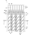
- Fig. 1 is a plan view showing the wiring member 10 according to embodiment 1.
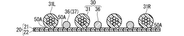
- Fig. 2 is a cross-sectional view taken along line II-II in Fig. 1.
- the wiring member 10 comprises a base member 20 and a plurality of linear transmission members 30.
- the base member 20 is formed into a flat shape overall.
- the plurality of linear transmission members 30 are linear members that transmit electricity, light, etc.
- the plurality of linear transmission members 30 are arranged side by side on the base member 20.
- the plurality of linear transmission members 30 are fixed to the base member 20, thereby maintaining the wiring member 10 in a flat shape.
- the base member 20 is formed in a sheet shape.
- the base member 20 keeps the multiple linear transmission members 30 aligned.
- the base member 20 is formed from a resin material.
- the material that constitutes the base member 20 may be a material other than resin, such as a metal or an inorganic material.
- the structure of the base member 20 may be a single-layer structure or a multi-layer structure of two or more layers.
- the layer structure of the base member 20 is not particularly limited.
- the base member 20 may have a layer constituted by a sheet having a uniform solid cross-section (also called a non-foamed sheet or solid sheet).
- the base member 20 may have a layer constituted by a foamed sheet or the like.
- the base member 20 may have a layer constituted by a fibrous sheet such as a knitted fabric, woven fabric, or nonwoven fabric.
- the base member 20 may be a soft member.
- the base member 20 may have flexibility that allows it to follow the bending of the linear transmission member 30.
- the wiring member 10 may be capable of bending in the thickness direction (bending such that the folds run along the main surface of the base member 20).
- the multiple linear transmission members 30 include at least one coated linear transmission member 31 and multiple bare electric wires 36.
- the coated linear transmission member 31 transmits electricity or light, etc.
- the bare electric wires 36 transmit electricity.
- the bare electric wire 36 is an electric wire that does not have an insulating coating layer 33 that covers the conductor.
- the bare electric wire 36 is a stranded wire in which multiple strands 37 are twisted together. In the twisted wire, the multiple strands 37 are joined together to form a single conductive path.
- the bare electric wire 36 may also be made up of a single strand 37.
- the coated linear transmission member 31 has a transmission line body 32 and a coating layer 33 that covers the periphery of the transmission line body 32.
- the transmission line body 32 is a part that transmits electricity or light.
- the coated linear transmission member 31 is a coated electric wire 31 having a conductor core 32 and an insulating coating layer 33 that covers the periphery of the conductor core 32.
- the coated electric wire 31 is a general coated electric wire that does not have a shielding layer around the insulating coating layer 33.
- the coated electric wire 31 may be a shielded wire that has a shielding layer around the insulating coating layer 33.
- the coated linear transmission member 31 may be an enameled wire, a nichrome wire (heating wire), an optical fiber, or the like.
- the coated linear transmission member 31 is a single linear object with one transmission path.
- the coated linear transmission member 31 may also be a composite of multiple linear objects each having a different transmission path (such as a twisted wire or a cable made up of multiple linear objects assembled together and covered with a sheath).
- the linear transmission member 30 that transmits electricity may be any of various signal lines or power lines. A part of the linear transmission member 30 that transmits electricity may be used as an antenna, coil, etc. that sends signals or power to or receives signals or power from space.
- a coated linear transmission member 31 is arranged between multiple bare electric wires 36.
- the space between the parallel bare electric wires 36 is defined as an arrangement space.
- the number of arrangement spaces is the number of parallel bare electric wires 36 minus one.
- the number of arrangement spaces may be one or more.
- the coated linear transmission member 31 is arranged in the arrangement space so that the bare electric wires 36 are not adjacent to each other. When there are multiple arrangement spaces, a coated linear transmission member 31 is arranged in each arrangement space.
- the number of coated linear transmission members 31 is the same as or greater than the number of arrangement spaces.
- only one coated linear transmission member 31 is arranged in one arrangement space.
- the bare wires 36 and the coated linear transmission member 31 are arranged alternately between the bare wire 36 on one outer side along the parallel direction and the bare wire 36 on the other outer side. This makes it possible to increase the ratio of bare wires 36 to the multiple linear transmission members 30.
- multiple coated linear transmission members 31 may be arranged in one arrangement space, and the coated linear transmission members 31 may be adjacent to each other.
- the coated linear transmission member 31 has a first outer linear transmission member 31L arranged on one outer side of the multiple linear transmission members 30 arranged in parallel on the base member 20, and a second outer linear transmission member 31R arranged on the other outer side. Therefore, here, the coated linear transmission members 31 are arranged on both sides of all parallel bare electric wires 36.
- the number of coated linear transmission members 31 is one or more more than the number of bare electric wires 36 and two or more more than the number of arrangement spaces.
- the height of the coated linear transmission member 31 from the arrangement surface 23 of the base member 20 is higher than the height of the bare electric wire 36 from the arrangement surface 23.
- the coated linear transmission member 31 and the bare electric wire 36 are so-called round electric wires with a circular cross section. Therefore, the height of the coated linear transmission member 31 and the bare electric wire 36 from the arrangement surface 23 is approximately the same as the thickness (diameter) of the coated linear transmission member 31 and the bare electric wire 36. The difference in height occurs because the coated linear transmission member 31 is thicker than the bare electric wire 36. Note that the coated linear transmission member 31 or the bare electric wire 36 may be other than a round electric wire.
- the coated linear transmission member 31 is a so-called rectangular electric wire with a rectangular cross section
- the height of the coated linear transmission member 31 from the arrangement surface 23 is approximately the same as the length of the short side direction of the rectangular electric wire.
- the dimensions of the transmission line body 32 are the same as or larger than the dimensions of the bare electric wire 36 in the direction perpendicular to the arrangement surface 23.
- the coated linear transmission member 31 and the bare electric wire 36 are round electric wires, and therefore the thickness of the transmission line body 32 is the same as or larger than the thickness of the bare electric wire 36, resulting in the dimensional difference in the direction perpendicular to the arrangement surface 23.
- the height of the coated linear transmission member 31 from the arrangement surface 23 is higher than the height of the bare electric wire 36 from the arrangement surface 23 by at least the thickness of the coating layer 33.
- the wiring member 10 may include electric wires that are used as signal lines and electric wires that are used as power lines.
- all bare electric wires 36 may be signal lines.
- all electric wires that are used as signal lines may be bare electric wires 36.
- some of the electric wires that are used as signal lines may be bare electric wires 36, and other parts may be covered electric wires 31.
- all electric wires that are used as power lines may be covered electric wires 31.
- the wiring member 10 may include a plurality of electric wires having different conductor sizes.
- the smallest conductor size among the plurality of conductor sizes is referred to as the first conductor size
- the next smallest conductor size after the first conductor size is referred to as the second conductor size.
- the bare electric wires 36 may be composed only of electric wires of the first conductor size, and the electric wires of the second conductor size and larger conductor sizes may be referred to as covered electric wires 31. All electric wires of the first conductor size may be referred to as bare electric wires 36.
- a portion of the electric wires of the first conductor size may be referred to as bare electric wires 36, and another portion may be referred to as covered electric wires 31.
- the multiple linear transmission members 30 are members that connect components in a vehicle.
- a connector 40 is provided at the end of the linear transmission member 30.
- This connector 40 is connected to a mating connector provided on a mating component, thereby connecting the linear transmission member 30 to the mating component.
- this wiring member 10 is used as a wiring member 10 that electrically (or optically) connects various components in a vehicle or the like.
- the connector 40 may be fixed to the base member 20.
- the end of the linear transmission member 30 may extend outside the base member 20, and the connector 40 may be provided away from the base member 20.
- the connector 40 may include a terminal 41 and a connector housing 46.
- the terminal 41 has a first connection portion 42 that is connected to a mating terminal in a mating connector, and a second connection portion 43 that is connected to the linear transmission member 30.
- the configuration of the first connection portion 42 can be set appropriately, and may be, for example, a male terminal structure or a female terminal structure.
- the terminal 41 may include a terminal 41A for the coated electric wire 31 and a terminal 41B for the bare electric wire 36, in which the shapes of the second connection portion 43 are different from each other.
- the second connection portion 43A in the terminal 41A for the coated electric wire 31 has a wire barrel 44 that is crimped to the conductor core wire and an insulation barrel 45 that is crimped to the insulating coating layer 33.
- the second connection portion 43B in the terminal 41B for the bare electric wire 36 has a wire barrel 44 but does not have an insulation barrel 45.
- the covered electric wires 31 and bare electric wires 36 are connected to the same connector 40.
- the same covered electric wires 31 and bare electric wires 36 may be connected to different connectors 40.
- the arrangement of the covered electric wires 31 and bare electric wires 36 in the connector 40 and the arrangement of the covered electric wires 31 and bare electric wires 36 in the base member 20 are the same.
- the arrangement of the covered electric wires 31 and bare electric wires 36 in the connector 40 and the arrangement of the covered electric wires 31 and bare electric wires 36 in the base member 20 may be different from each other.
- the paths of the multiple linear transmission members 30 are set according to the positions of the components to which they are connected. By fixing the multiple linear transmission members 30 to the base member 20, the multiple linear transmission members 30 are maintained along wiring paths that correspond to the positions of the components to which they are connected.
- the multiple linear transmission members 30 may be fixed to the base member 20 in a manner in which branch lines branch off from a main line. It is sufficient that the wiring member 10 has a portion in which the multiple linear transmission members 30 are parallel.
- the linear transmission member 30 only needs to be fixed to the base member 20, and the fixing structure of the linear transmission member 30 to the base member 20 is not particularly limited.
- the linear transmission member 30 is fixed to the base member 20.
- Such a fixing manner may be fixing at the contact portion, fixing at the non-contact portion, or a combination of both.
- fixing at the contact portion means that the contact portion of the linear transmission member 30 and the base member 20 are fixed by adhering to each other.
- Fixing at the non-contact portion means a fixing manner that is not fixing at the contact portion, and for example, a sewing thread 51, a cover, an adhesive tape, etc., presses the linear transmission member 30 against the base member 20, or sandwiches the linear transmission member 30 and the base member 20, and maintains that state.
- the fixing portion 50 between the linear transmission member 30 and the base member 20 is fixed in a non-contacting state.
- the linear transmission member 30 and the base member 20 are fixed by a sewing thread 51.
- the fixing portion 50 is formed by the sewing thread 51.
- the pitch of the sewing thread 51 can be set as appropriate.
- the pitch of the sewing thread 51 of the bare electric wire 36 is the same as the pitch of the sewing thread 51 of the covered electric wire 31.
- the pitch of the sewing thread 51 of the bare electric wire 36 and the pitch of the sewing thread 51 of the covered electric wire 31 may be different from each other.
- First modified example of fixing manner between linear transmission member 30 and base member 20> 3 is a cross-sectional view showing a first modified example of the fixing mode between the linear transmission member 30 and the base member 20.
- this modified example the same components as those described so far are given the same reference numerals and the description thereof is omitted. The same applies to the following embodiments and modified examples.
- the fixing portion 50A between the linear transmission member 30 and the base member 20 is in a state of being fixed at the contact portion.
- the manner of fixing the contact portion may be indirect fixing of the contact portion, direct fixing of the contact portion, or a combination of the two in different regions.
- indirect fixing of the contact portion means that the linear transmission member 30 and the base member 20 are indirectly attached and fixed to each other via an adhesive, pressure sensitive adhesive, double-sided adhesive tape, or the like provided between them.
- Direct fixing of the contact portion means that the linear transmission member 30 and the base member 20 are directly attached and fixed to each other without using a separate adhesive or the like. In direct fixing of the contact portion, for example, it is considered that the resin contained in at least one of the linear transmission member 30 and the base member 20 is melted to adhere and fix them to each other.
- the resin When such a state of direct fixation of the contact areas is formed, the resin may be melted, for example, by heat or by a solvent.
- the state of direct fixation of the contact areas may be a state of direct fixation of the contact areas by heat or a state of direct fixation of the contact areas by a solvent.
- the state of direct fixation of the contact areas is a state of direct fixation of the contact areas by heat.
- the means for forming the state where the contact parts are directly fixed at this time is not particularly limited, and known means such as welding, fusion, and welding can be used.
- various welding means such as ultrasonic welding, heat and pressure welding, hot air welding, and high frequency welding can be used.
- the linear transmission member 30 and the base member 20 are in a state where they are directly fixed at the contact parts by that means.
- the linear transmission member 30 and the base member 20 are in a state where they are directly fixed at the contact parts by ultrasonic welding.
- the linear transmission member 30 and the base member 20 are in a state where they are directly fixed at the contact parts by ultrasonic welding.
- the linear transmission member 30 and the base member 20 are in a state where they are directly fixed at the contact parts.
- the linear transmission member 30 and the base member 20 are in a state where they are directly fixed at the contact parts.
- the base member 20 may have a two-layer structure including a first layer 21 and a second layer 22.
- the first layer 21 is a fixing layer.
- the linear transmission member 30 is directly fixed to the fixing layer at the contact area.
- the fixing layer includes a resin material, preferably a thermoplastic resin material.
- the resin material of the fixing layer softens and is directly fixed to the fixing partner at the contact area.
- the type of such resin material is not particularly limited, and polyvinyl chloride (PVC), polyethylene (PE), polypropylene (PP), polyethylene terephthalate (PET), etc. can be used. It is preferable that the coating layer 33 also has the same resin material as the fixing layer.
- One surface of the first layer 21 is one main surface of the base member 20.
- the second layer 22 is an additional layer.
- the second layer 22 is formed of a different material from the fixed layer, or has a different structure.
- the second layer 22 enhances the functions of the fixed layer, or adds functions not present in the fixed layer to the base member 20.
- the material constituting the second layer 22 may be a metal, an inorganic substance, etc., in addition to the materials described for the fixed layer above.
- One surface of the second layer 22 is the other main surface of the base member 20.
- the first layer 21 and the second layer 22 are fixed together while the other surface of the first layer 21 and the other surface of the second layer 22 are in contact with each other.
- the manner in which the first layer 21 and the second layer 22 are fixed together is not particularly limited, but it is preferable that they are fixed together by direct or indirect fixing at the contacting portions.
- a resin material or adhesive can be inserted into the voids to fix them together. This produces a so-called anchor effect, and the first layer 21 and the second layer 22 are firmly fixed together.
- the first layer 21 is described as a solid sheet made of resin
- the second layer 22 is described as a fibrous sheet.
- the first layer 21 and the second layer 22 are described as being directly fixed at the contact area.
- the resin of the first layer 21 penetrates between the fibers of the second layer 22 in a fluid state and is then hardened. This maintains the state in which the resin of the first layer 21 penetrates between the fibers of the second layer 22, and the first layer 21 and the second layer 22 are firmly fixed together.
- the first layer 21 and the second layer 22 may be formed to be the same size (same planar shape). One of the first layer 21 and the second layer 22 may be formed larger than the other.
- the first layer 21 and the second layer 22 are fixed over the entire area of contact.
- the first layer 21 and the second layer 22 may be fixed over only a portion of the area of contact.
- the first layer 21 may be a solid sheet made of a soft resin such as soft PVC
- the second layer 22 may be a nonwoven fabric made of PET, so that the base member 20 is a soft member.
- the coating layer 33 of the coated linear transmission member 31 and the first layer 21 contain the same resin as the main component. This allows both the coating layer 33 of the coated linear transmission member 31 and the first layer 21 to soften and bond with the other resin. Also, when the contact area is directly fixed, the resin of the first layer 21 softens and bonds to the twisted wire. Note that in the example shown in Figure 3, the bare wire 36 is not twisted wire, but is made of a single wire 37. The twisted wire may be fixed to the base member 20 at the contact area.
- each of the multiple linear transmission members 30 may be fixed in a series along the entire length of the base member 20.
- Each of the multiple linear transmission members 30 may be fixed to the base member 20 at multiple points spaced apart along the length.
- the multiple linear transmission members 30 may be fixed at the contact points of the base member 20 at the same position along the length.
- the multiple linear transmission members 30 may be fixed at the contact points of the base member 20 at different positions along the length. In one linear transmission member 30, the spacing between the multiple fixing points may be the same or different.
- FIG. 4 is a cross-sectional view showing a second modified example of the manner in which the linear transmission member 30 and the base member 20 are fixed to each other.
- the fixing manner between the bare electric wire 36 and the base member 20 is different from the fixing manner between the coated linear transmission member 31 and the base member 20.
- the bare electric wire 36 is provided with a fixing part 50 fixed at a non-contact portion
- the coated linear transmission member 31 is provided with a fixing part 50A fixed at a contact portion.
- the fixing part 50 of the bare electric wire 36 is fixed to the base member 20 with a sewing thread 51, as in the example shown in FIG. 2.
- the fixing part 50A of the coated linear transmission member 31 is directly fixed to the base member 20 at a contact portion, as in the example shown in FIG. 3.
- the combination of the fixing part of the coated linear transmission member 31 and the fixing part of the bare electric wire 36 can be set as appropriate.
- the wiring member 10 since the wiring member 10 includes the bare electric wire 36, the material cost can be reduced by the coating layer 33 of the bare electric wire 36, compared to the case where the coated electric wire 31 is provided instead of the bare electric wire 36. Since the coated linear transmission member 31 is disposed between the bare electric wires 36, the bare electric wires 36 are prevented from being adjacent to each other, and unintended short circuits between the bare electric wires 36 can be prevented.
- the width dimension (the distance between the first outer linear transmission member 31L and the second outer linear transmission member 31R) when the multiple linear transmission members 30 are arranged can be reduced compared to the case where a coated electric wire is used instead of the bare electric wires 36. This allows the width dimension of the base member 20 to be reduced, and the material cost can be reduced accordingly.
- the height of the coated linear transmission member 31 from the arrangement surface 23 is higher than the height of the bare electric wires 36 from the arrangement surface 23. This allows the coated linear transmission member 31 between the bare electric wires 36 to function as an insulating wall higher than the bare electric wires 36. This makes it difficult for conductive dust or dirt to come into contact with the bare electric wires 36 on the other side of the coated linear transmission member 31 when the dust or dirt straddles the coated linear transmission member 31 and the bare electric wires 36 on one side of the coated linear transmission member 31.
- the dimensions of the transmission line body 32 of the coated linear transmission member 31 are equal to or larger than the dimensions of the bare wire 36. This allows the difference in height between the coated linear transmission member 31 and the bare wire 36 from the placement surface 23 to be large.
- At least one coated linear transmission member 31 has a first outer linear transmission member 31L arranged on one outer side of the multiple linear transmission members 30 arranged in parallel on the base member 20, and a second outer linear transmission member 31R arranged on the other outer side. This makes it possible to prevent the bare wire 36 from being exposed to the side of the wiring member 10.
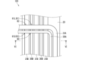
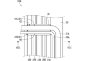
- Fig. 5 is a plan view showing a wiring member 110 according to embodiment 2.
- Fig. 6 is a cross-sectional view taken along line VI-VI in Fig. 5.
- the wiring member 110 has an intersection where multiple linear transmission members 30 cross each other in a plan view.
- the intersection where bare electric wires 36 cross each other is referred to as the first intersection 60.
- the intersection where bare electric wires 36 cross each other and coated linear transmission member 31 cross each other is referred to as the second intersection 61.
- the second intersection 61 may include a second intersection 61L where bare electric wires 36 are located closer to the base member 20 (lower side) than coated linear transmission member 31, and a second intersection 61U where coated linear transmission member 31 is located closer to the base member 20 (lower side) than bare electric wires 36.
- intersections in the wiring member 110 include at least one of a group consisting of a first intersection 60, a second intersection 61, and a third intersection 62. In the example shown in FIG. 5, the intersections include a first intersection 60, a second intersection 61, and a third intersection 62.
- bare electric wire 36A intersects with bare electric wire 36B and covered electric wire 31B.
- covered electric wire 31A intersects with bare electric wire 36B and covered electric wire 31B.
- the intersection of bare electric wire 36A and bare electric wire 36B is a first intersection 60.
- the intersection of bare electric wire 36A and covered electric wire 31B is a second intersection 61U, and the intersection of covered electric wire 31A and bare electric wire 36B is a second intersection 61L.
- the intersection of covered electric wire 31A and covered electric wire 31B is a third intersection 62.
- bare electric wire 36A crosses bare electric wire 36B and covered electric wire 31B on both sides of bare electric wire 36B to form first intersection 60 and second intersection 61U.
- the height of covered electric wire 31B from the placement surface 23 of base member 20 is higher than the height of bare electric wire 36B.
- bare electric wire 36A is supported in contact with covered electric wire 31B.
- bare electric wire 36A is supported above bare electric wire 36B with a gap between them.
- bare electric wires 36A,B that cross each other are not in contact with each other. There is a hollow space between bare electric wires 36A,B.
- the intersections are provided to allow the linear transmission members 30 to branch off from each other.
- the bare wire 36A and the covered wire 31B cross over the bare wire 36B and the covered wire 31B to branch off from the bare wire 36B and the covered wire 31B.
- the bare wire 36A and the covered wire 31A are parallel to the bare wire 36B and the covered wire 31B on one end side of the intersection.
- the bare wire 36A and the covered wire 31A extend in a different direction from the bare wire 36B and the covered wire 31B on the other end side of the intersection.
- the intersections may be provided to change the arrangement of the linear transmission members 30 in the parallel direction.
- the linear transmission member 30 is not folded back together with the base member 20 to form the intersection. At least one of the pair of linear transmission members 30 that form the intersection changes its path on the base member 20 individually with respect to the base member 20, without being folded back together with the base member 20.
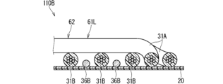
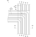
- Fig. 7 is a plan view showing a first modified example of the wiring member 110 according to embodiment 2.
- Fig. 8 is a cross-sectional view taken along line VIII-VIII in Fig. 7.
- the wiring member 110A shown in FIG. 7 includes an insulating sheet 70 disposed between the bare wires 36 that cross each other at the first intersection 60.
- the insulating sheet 70 is partially provided in a region including the first intersection 60 with respect to the base member 20.
- this region includes the second intersection 61 adjacent to the first intersection 60.
- This region also includes the second intersection 61U where the bare wire 36 forming the first intersection 60 intersects with the coated wire 31 adjacent to the first intersection 60.
- This region also includes the second intersection 61L and the third intersection 62 where the coated wire 31A parallel to the bare wire 36 forming the first intersection 60 intersects with the bare wire 36B and the coated wire 31B.
- the region where the insulating sheet 70 is provided may include only the first intersection 60 without including the second intersection 61 and the third intersection 62.
- the region where the insulating sheet 70 is provided may include only the first intersection 60 and the second intersection 61L without including the second intersection 61U and the third intersection 62.
- the area in which the insulating sheet 70 is provided may not include the second intersection 61L and the third intersection 62, but may include only the first intersection 60 and the second intersection 61U.
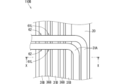
- Fig. 9 is a plan view showing a second modified example of the wiring member 110 according to embodiment 2.
- Fig. 10 is a cross-sectional view taken along line XX in Fig. 9.
- the intersection may be configured not to include the first intersection 60.
- the intersection of the wiring member 110B according to the second modified example does not include the first intersection 60, but only includes the second intersection 61 and the third intersection 62.
- the intersection may not include the first intersection 60 and the third intersection 62, but only includes the second intersection 61.
- the intersection may not include the first intersection 60 and the second intersection 61, but only includes the third intersection 62.
- the wiring members 110, 110A, and 110B according to the second embodiment and its modifications can also provide the same effects as the wiring member 10 according to the first embodiment.
- wiring members 110, 110A, and 110B have intersections where the multiple linear transmission members 30 cross each other in a planar view, which increases the degree of freedom of the paths of the multiple linear transmission members 30 on the base member 20 compared to when no intersections are provided.
- the intersection includes a first intersection 60. This increases the degree of freedom of the path of the bare wires 36 on the base member 20 compared to a case in which the first intersection 60 is not provided.
- the intersections include a first intersection 60, a second intersection 61, and a third intersection 62. This increases the degree of freedom of the paths of the bare wires 36 and the coated linear transmission members 31 on the base member 20.
- the height of the covered electric wires 31B on both sides of the bare electric wire 36B from the arrangement surface 23 is greater than the height of the bare electric wire 36B from the arrangement surface 23, and there is a hollow space between the mutually intersecting bare electric wires 36A, 36B at the first intersection 60. This makes it possible to prevent a short circuit between the bare electric wires 36A, 36B at the first intersection 60 without providing an insulating sheet 70 or the like.
- the insulating sheet 70 can prevent short circuits between the bare wires 36 at the first intersection 60.
- the insulating sheet 70 is partially provided in an area including the first intersection 60 relative to the base member 20, which helps prevent the insulating sheet 70 from becoming too large.
- the insulating sheet 70 has higher insulating properties than the base member 20, so the insulating sheet 70 can be made thinner than the base member 20, and an increase in the thickness of the wiring member 10 can be suppressed.
- the wiring member 110B prevents the bare wires 36 from crossing each other, making it easier to prevent short circuits between the bare wires 36.
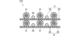
- FIG. 11 is a plan view showing a wiring member 210 according to embodiment 3.
- Fig. 12 is a cross-sectional view taken along line XII-XII in Fig. 11.
- the wiring member 210 includes a first wiring body 11 and a second wiring body 12 stacked on each other.
- Each of the first wiring body 11 and the second wiring body 12 includes a base member 20 and a plurality of linear transmission members 30.
- the base member 20 of the first wiring body 11 is in contact with at least one of the plurality of linear transmission members 30 of the second wiring body 12.
- the coated electric wires 31 overlap each other and the bare electric wires 36 overlap each other.
- the base member 20 of the first wiring body 11 is in contact with the coated electric wire 31 of the second wiring body 12.
- the base member 20 of the first wiring body 11 may have higher insulation than the base member 20 of the second wiring body 12.
- the nonwoven fabric of the base member 20 of the first wiring body 11 may be configured similarly to the nonwoven fabric of the insulating sheet 70.
- the first wiring body 11 and the second wiring body 12 are stacked in portions that extend along the same path. In the example shown in FIG. 11, the first wiring body 11 and the second wiring body 12 branch off midway, eliminating the stacked state.
- the wiring member 210 is provided with a stacked extension portion in which the first wiring body 11 and the second wiring body 12 are stacked and extend along the same path, and an individual extension portion in which the first wiring body 11 and the second wiring body 12 extend individually without being stacked.
- the first wiring body 11 and the second wiring body 12 may remain stacked from one end to the other without branching off midway.
- the wiring member 210 may not be provided with an individual extension portion.
- the wiring member 210 has an intersection where the bare electric wire 36 of the first wiring body 11 and the bare electric wire 36 of the second wiring body 12 cross each other. As shown in FIG. 11, when the first wiring body 11 bends and branches off from the common path with the second wiring body 12, the bare electric wire 36 of the first wiring body 11 and the bare electric wire 36 of the second wiring body 12 cross each other to provide a first intersection 60. At the first intersection 60, the base member 20 of the first wiring body 11 is located between the bare electric wire 36 of the first wiring body 11 and the bare electric wire 36 of the second wiring body 12.
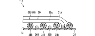
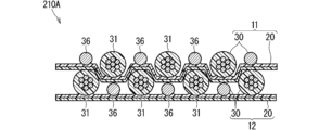
- FIG. 13 is a cross-sectional view showing a first modified example of the wiring member 210 according to the third embodiment.
- the bare electric wire 36 of the first wiring body 11 and the coated linear transmission member 31 of the second wiring body 12 overlap each other and extend in the same direction
- the coated linear transmission member 31 of the first wiring body 11 and the bare electric wire 36 of the second wiring body 12 overlap each other and extend in the same direction.
- the first wiring body 11 is deformed so that the coated electric wire 31 of the first wiring body 11 enters the space above the bare electric wire 36 of the second wiring body 12 and between the coated electric wires 31.
- the wiring members 210 and 210A according to the third embodiment and its modified example can also provide the same effect as the wiring member 10 according to the first embodiment.
- the width dimension (the distance between the first outer linear transmission member 31L and the second outer linear transmission member 31R) when multiple linear transmission members 30 are arranged can be made smaller than when a covered electric wire is used instead of the bare electric wires 36.
- This increases the number of multiple linear transmission members that can be arranged side by side on one base member having a predetermined width. This can reduce the number of layers in the laminated portion, compared to when a covered electric wire is used instead of the bare electric wires 36, thereby reducing the material cost.
- the base member 20 of the first wiring body 11 can be used as a cover member for the multiple linear transmission members 30 of the second wiring body 12.
- the base member 20 of the first wiring body 11 is positioned between the bare electric wire 36 of the first wiring body 11 and the bare electric wire 36 of the second wiring body 12.
- the base member 20 can prevent short circuits between the bare electric wires 36 at the intersection where the bare electric wires 36 intersect.
- the coated linear transmission member 31 and the bare wire 36 overlap between different wiring bodies, which prevents the thickness of the wiring member 10 from increasing.
- a cover member that covers the linear transmission member 30 from the opposite side to the base member 20 is not provided.
- a cover member that covers the linear transmission member 30 from the opposite side to the base member 20 may be provided.
- Such a cover member may be fixed to the base member 20 without being fixed to the linear transmission member 30.
- the cover member may be in contact with the linear transmission member 30, but may not be fixed thereto.
Landscapes
- Engineering & Computer Science (AREA)
- Architecture (AREA)
- Civil Engineering (AREA)
- Structural Engineering (AREA)
- Details Of Indoor Wiring (AREA)
- Insulated Conductors (AREA)
- Installation Of Indoor Wiring (AREA)
Priority Applications (1)
| Application Number | Priority Date | Filing Date | Title |
|---|---|---|---|
| CN202480016973.6A CN121039758A (zh) | 2023-03-13 | 2024-02-22 | 布线构件 |
Applications Claiming Priority (2)
| Application Number | Priority Date | Filing Date | Title |
|---|---|---|---|
| JP2023-038451 | 2023-03-13 | ||
| JP2023038451A JP2024129322A (ja) | 2023-03-13 | 2023-03-13 | 配線部材 |
Publications (1)
| Publication Number | Publication Date |
|---|---|
| WO2024190359A1 true WO2024190359A1 (ja) | 2024-09-19 |
Family
ID=92755523
Family Applications (1)
| Application Number | Title | Priority Date | Filing Date |
|---|---|---|---|
| PCT/JP2024/006501 Pending WO2024190359A1 (ja) | 2023-03-13 | 2024-02-22 | 配線部材 |
Country Status (3)
| Country | Link |
|---|---|
| JP (1) | JP2024129322A (enExample) |
| CN (1) | CN121039758A (enExample) |
| WO (1) | WO2024190359A1 (enExample) |
Citations (2)
| Publication number | Priority date | Publication date | Assignee | Title |
|---|---|---|---|---|
| JP2019204745A (ja) * | 2018-05-25 | 2019-11-28 | 株式会社オートネットワーク技術研究所 | 積層型配線部材 |
| JP2021174644A (ja) * | 2020-04-23 | 2021-11-01 | 東京特殊電線株式会社 | 同軸フラットケーブル |
-
2023
- 2023-03-13 JP JP2023038451A patent/JP2024129322A/ja active Pending
-
2024
- 2024-02-22 CN CN202480016973.6A patent/CN121039758A/zh active Pending
- 2024-02-22 WO PCT/JP2024/006501 patent/WO2024190359A1/ja active Pending
Patent Citations (2)
| Publication number | Priority date | Publication date | Assignee | Title |
|---|---|---|---|---|
| JP2019204745A (ja) * | 2018-05-25 | 2019-11-28 | 株式会社オートネットワーク技術研究所 | 積層型配線部材 |
| JP2021174644A (ja) * | 2020-04-23 | 2021-11-01 | 東京特殊電線株式会社 | 同軸フラットケーブル |
Also Published As
| Publication number | Publication date |
|---|---|
| CN121039758A (zh) | 2025-11-28 |
| JP2024129322A (ja) | 2024-09-27 |
Similar Documents
| Publication | Publication Date | Title |
|---|---|---|
| JP7647834B2 (ja) | 配線部材 | |
| JP7597182B2 (ja) | 配線部材 | |
| JP7384084B2 (ja) | 配線部材 | |
| JP7537117B2 (ja) | 配線部材 | |
| WO2019230080A1 (ja) | 配線部材 | |
| CN115362512B (zh) | 配线部件 | |
| JP7334610B2 (ja) | 配線部材 | |
| JP7404971B2 (ja) | 配線部材 | |
| JP7428073B2 (ja) | 配線部材 | |
| JP7600900B2 (ja) | 配線部材 | |
| JP7200885B2 (ja) | 配線部材 | |
| WO2024190359A1 (ja) | 配線部材 | |
| JP7459583B2 (ja) | 配線部材 | |
| JP7211331B2 (ja) | 配線部材 | |
| WO2022202667A1 (ja) | 配線部材 | |
| JP2025133177A (ja) | 配線部材及び配線部材の製造方法 | |
| JP7453927B2 (ja) | 融着シート及び配線部材 | |
| WO2024203842A1 (ja) | 配線部材 | |
| JP2025104453A (ja) | 配線部材及び配線部材の製造方法 | |
| WO2025158944A1 (ja) | 配線部材 |
Legal Events
| Date | Code | Title | Description |
|---|---|---|---|
| 121 | Ep: the epo has been informed by wipo that ep was designated in this application |
Ref document number: 24770472 Country of ref document: EP Kind code of ref document: A1 |
|
| NENP | Non-entry into the national phase |
Ref country code: DE |