WO2024189790A1 - 圧延製品の材質特性予測装置 - Google Patents
圧延製品の材質特性予測装置 Download PDFInfo
- Publication number
- WO2024189790A1 WO2024189790A1 PCT/JP2023/009919 JP2023009919W WO2024189790A1 WO 2024189790 A1 WO2024189790 A1 WO 2024189790A1 JP 2023009919 W JP2023009919 W JP 2023009919W WO 2024189790 A1 WO2024189790 A1 WO 2024189790A1
- Authority
- WO
- WIPO (PCT)
- Prior art keywords
- rolling
- unit
- model
- rolled
- approximation model
- Prior art date
- Legal status (The legal status is an assumption and is not a legal conclusion. Google has not performed a legal analysis and makes no representation as to the accuracy of the status listed.)
- Ceased
Links
Images







Classifications
-
- B—PERFORMING OPERATIONS; TRANSPORTING
- B21—MECHANICAL METAL-WORKING WITHOUT ESSENTIALLY REMOVING MATERIAL; PUNCHING METAL
- B21B—ROLLING OF METAL
- B21B37/00—Control devices or methods specially adapted for metal-rolling mills or the work produced thereby
-
- G—PHYSICS
- G05—CONTROLLING; REGULATING
- G05B—CONTROL OR REGULATING SYSTEMS IN GENERAL; FUNCTIONAL ELEMENTS OF SUCH SYSTEMS; MONITORING OR TESTING ARRANGEMENTS FOR SUCH SYSTEMS OR ELEMENTS
- G05B19/00—Program-control systems
- G05B19/02—Program-control systems electric
- G05B19/418—Total factory control, i.e. centrally controlling a plurality of machines, e.g. direct or distributed numerical control [DNC], flexible manufacturing systems [FMS], integrated manufacturing systems [IMS] or computer integrated manufacturing [CIM]
- G05B19/41875—Total factory control, i.e. centrally controlling a plurality of machines, e.g. direct or distributed numerical control [DNC], flexible manufacturing systems [FMS], integrated manufacturing systems [IMS] or computer integrated manufacturing [CIM] characterised by quality surveillance of production
-
- B—PERFORMING OPERATIONS; TRANSPORTING
- B21—MECHANICAL METAL-WORKING WITHOUT ESSENTIALLY REMOVING MATERIAL; PUNCHING METAL
- B21B—ROLLING OF METAL
- B21B38/00—Methods or devices for measuring, detecting or monitoring specially adapted for metal-rolling mills, e.g. position detection, inspection of the product
-
- G—PHYSICS
- G06—COMPUTING OR CALCULATING; COUNTING
- G06N—COMPUTING ARRANGEMENTS BASED ON SPECIFIC COMPUTATIONAL MODELS
- G06N20/00—Machine learning
-
- G—PHYSICS
- G06—COMPUTING OR CALCULATING; COUNTING
- G06Q—INFORMATION AND COMMUNICATION TECHNOLOGY [ICT] SPECIALLY ADAPTED FOR ADMINISTRATIVE, COMMERCIAL, FINANCIAL, MANAGERIAL OR SUPERVISORY PURPOSES; SYSTEMS OR METHODS SPECIALLY ADAPTED FOR ADMINISTRATIVE, COMMERCIAL, FINANCIAL, MANAGERIAL OR SUPERVISORY PURPOSES, NOT OTHERWISE PROVIDED FOR
- G06Q10/00—Administration; Management
- G06Q10/04—Forecasting or optimisation specially adapted for administrative or management purposes, e.g. linear programming or "cutting stock problem"
-
- B—PERFORMING OPERATIONS; TRANSPORTING
- B21—MECHANICAL METAL-WORKING WITHOUT ESSENTIALLY REMOVING MATERIAL; PUNCHING METAL
- B21B—ROLLING OF METAL
- B21B2261/00—Product parameters
-
- G—PHYSICS
- G05—CONTROLLING; REGULATING
- G05B—CONTROL OR REGULATING SYSTEMS IN GENERAL; FUNCTIONAL ELEMENTS OF SUCH SYSTEMS; MONITORING OR TESTING ARRANGEMENTS FOR SUCH SYSTEMS OR ELEMENTS
- G05B2219/00—Program-control systems
- G05B2219/30—Nc systems
- G05B2219/32—Operator till task planning
- G05B2219/32193—Ann, neural base quality management
Definitions
- the present disclosure relates to a device for predicting material properties of rolled products, and more specifically, to a device for predicting material properties of rolled products manufactured in a hot rolling process.
- the material properties of rolled products (hereinafter also referred to as "products") made of metal materials such as steel vary depending on the alloy composition, and the heating, processing, and cooling conditions of the hot rolling process.
- Material properties include, for example, mechanical properties (strength, formability, toughness, etc.) and electromagnetic properties (magnetic permeability, etc.).
- the alloy composition is adjusted by controlling the amount of added component elements. When adjusting the composition, a single lot unit is large, for example, a composition adjustment furnace that can hold about 100 tons of molten steel is used. Therefore, it is impossible to change the amount of added for each individual rolled product, which is about 15 tons. Therefore, in order to manufacture hot rolled product coils of the desired material, it is important to properly control the heating, processing, and cooling conditions.
- Process parameters include, for example, the target temperatures at each point on the rolling line, such as the entry and exit temperatures of the finishing mill and the coiling temperature, schedules related to the reduction of plate thickness and width, such as the transfer bar thickness at the exit of the roughing mill and the reduction rate of each pass, whether or not to use the descalers installed on the finishing mill and roughing mill for each pass, whether or not to use interstand cooling located between the stands of the roughing mill and finishing mill and the initial flow rate used, the amount of lubricating oil used on the finishing mill, and the cooling pattern used on the run-out table.
- process parameters related to heating, processing and cooling were set for each rolled product specification, with target heating temperature, target dimensions after processing and target cooling rate, and a method of controlling temperature and dimensions to achieve these target values was generally adopted. Note that while the target product dimensions were specified in advance, the target plate thickness, temperature and cooling rate at the exit of each stand were determined based on many years of experience. However, in recent years, requirements for product specifications have become increasingly sophisticated and diverse, and there are cases where these target values cannot always be determined appropriately using methods based on experience.
- Patent Document 1 discloses an apparatus that performs an offline simulation of a manufacturing process using a process model that models each of the manufacturing processes of heating, processing, and cooling in order to examine in advance whether a product manufactured under a certain alloy composition and process parameters will have the desired product quality.
- thermometers installed on the rolling line to manage the temperature of the entire rolled coil, and also to manage the material properties that are closely related to the rolling temperature.
- thermometers are installed at the exit of the heating furnace of the rolling line, the entry and exit of the roughing mill, the entry and exit of the finishing mill, the entry of the coiler, etc.
- the thermometer measures the temperature of the center of the material being rolled in the width direction (hereinafter simply referred to as the "width direction").
- a host computer controls the output value from the thermometer so that it matches a target temperature determined based on experience. In this way, conventionally, the material properties in the width direction of the material being rolled were not taken into consideration when managing the rolling process.
- the widthwise ends (edges) of the material being rolled tend to cool easily, resulting in a temperature difference between them and the center.
- rolling lines are equipped with devices to raise the temperature of the widthwise ends of the material being rolled and devices to prevent a drop in temperature at the widthwise ends of the material being rolled.
- edge masks are used to prevent cooling water from coming into contact with the edges during cooling after rolling.
- the edges are heated using induction heating devices such as edge heaters.
- scan pyrometers are sometimes installed before and after the above device to verify its effectiveness. Using a scan pyrometer, it is possible to measure the temperature distribution across the width of the material being rolled. Also, in the multi-gauges that have been adopted in rolling lines in recent years, scan pyrometers are used to use the temperature distribution across the width of the material being rolled to correct the measured values. Multi-gauges are composite measuring instruments that measure plate thickness, crown, plate width, etc. with a single unit, and their measurement accuracy has improved significantly in recent years.
- Patent Document 2 discloses a means for calculating the temperature distribution in the thickness direction and width direction of the rolled material.
- Patent Document 3 discloses a method for equalizing the temperature in the width direction by controlling edge heaters based on a calculation of the temperature distribution in the width direction.
- Patent Document 4 discloses a method of model learning using actual values of mechanical properties obtained from mechanical property measurement tests such as tensile tests and structure observations performed on some product coils for a model that mathematically represents metallurgical phenomena that predict changes in the microstructure of the rolled material and the mechanical properties of the final product.
- Patent Document 5 discloses a method of outputting a material distribution that correlates positions in two dimensions, the length and width directions, with material characteristic values.
- Patent Document 6 discloses a method of accumulating operating conditions and material records, searching for similar operating conditions, and estimating the material at every position of the product coil online in a mesh form.
- Patent Document 7 discloses a method of predicting material using a neural network.
- Japanese Patent No. 6292309 Japanese Patent No. 6197676 Japanese Patent No. 6447710 Japanese Patent No. 5396889 Japanese Patent Publication No. 2022-48037 Japanese Patent No. 6086155 Japanese Patent Publication No. 2005-315703
- Patent Documents 6 and 7 the relationship between past operating conditions and material performance is explored and modeled, and the material of a newly rolled product coil is predicted based on empirical rules. Such empirical models are generally known to be fast, and contribute to solving the problem of calculation load. However, models based on past operating conditions and material performance have limitations in the approximation accuracy when modeling complex material behavior, and sufficient prediction accuracy cannot be expected.
- This disclosure has been made to solve the problems described above.
- the purpose of this disclosure is to provide a rolled product material property prediction device that can quickly and accurately predict the material properties of an entire group of rolled products online.
- the first aspect relates to a rolled product material property prediction device that predicts the material properties of rolled products manufactured on a rolling line.
- the rolled product material property prediction device includes an approximation model creation unit that creates an approximation model offline that comprehensively predicts the material properties of a group of rolled products manufactured on the rolling line, and a material property prediction unit that uses the approximation model created by the approximation model creation unit to predict online the material properties in each area of a three-dimensional mesh of rolled products manufactured on the rolling line.
- the approximation model creation unit has a condition setting unit that sets the rolling conditions of the group of rolled products, and a material calculation unit that calculates metallurgical phenomena and material properties under the rolling conditions, and includes a dataset creation unit that creates a dataset used to create the approximation model, and a model parameter determination unit that uses the dataset to determine parameters that express the approximation model.
- the second viewpoint has the following feature in addition to the first viewpoint:
- the data set creation unit creates the data set in which the rolling conditions set by the condition setting unit are explanatory variables and the material properties calculated by the material calculation unit are objective variables.
- the third aspect has the following features in addition to those of the first aspect.
- the material property prediction unit includes a rolling data collection unit that collects rolling data obtained online when a rolled product is manufactured on the rolling line, a model input creation unit that creates input data for the approximation model online from the rolling data collected by the rolling data collection unit, an approximation model calculation unit that calculates the material properties of each area of a three-dimensional mesh of a product coil online by inputting the input data created by the model input creation unit into the approximation model, and a material property output unit that outputs the material properties of each area calculated by the approximation model calculation unit, information representing the position of each area in the rolled product, and information related to the material properties.
- the fourth aspect has the following features in addition to the first aspect:
- the approximation model is a machine learning model.
- the fifth aspect has the following characteristics in addition to any one of the first to fourth aspects:
- the material property prediction unit includes a material property correction unit that corrects the material properties calculated by the approximation model calculation unit using the approximation model, using material property results calculated using a metallurgical phenomenon model that mathematically represents metallurgical phenomena.
- the present disclosure by creating in advance data sets corresponding to rolling conditions (temperature conditions, processing conditions, time/speed conditions) that have not been implemented in an actual rolling process or rolling conditions that have little experience, and creating an approximation model offline using the created data sets, it is possible to create an approximation model that can be used for the entire group of rolled products and has high approximation accuracy.
- the approximation model created in this way it is possible to reduce the calculation load for online prediction of material properties in each area of a three-dimensional mesh of a rolled product.
- it is possible to quickly calculate the material properties of every area (part) of a rolled product it is also possible to reflect the results of the rolled product in the next rolled product or in operational changes to rolled products in the same lot.
- FIG. 1 is a diagram showing an example of a hot sheet rolling line to which a material property prediction device for a rolled product according to a first embodiment is applied.
- FIG. 1 is a block diagram showing a rolling system according to a first embodiment
- 1 is a block diagram showing the functions of a material property prediction device for a rolled product according to a first embodiment
- FIG. 1 is a diagram illustrating an example of a hardware configuration of a material property prediction device for a rolled product.
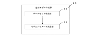
- FIG. 2 is a block diagram showing a configuration of an approximation model creation unit.
- FIG. 2 is a diagram for explaining a data set created by a data set creation unit.
- FIG. 13 is a schematic diagram for explaining an example of a cooling pattern of an explanatory variable.
- FIG. 1 is a diagram showing an example of a hot sheet rolling line to which a material property prediction device for a rolled product according to a first embodiment is applied.
- FIG. 1 is a block diagram showing a rolling system
- FIG. 2 is a diagram for explaining a configuration of a data set creation unit and creation of a data set.
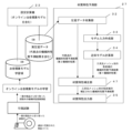
- FIG. 13 is a diagram for explaining the setting of a material calculation unit and explanatory variables by a condition setting unit.
- FIG. 13 is a diagram for explaining metallurgical phenomenon calculation by a material calculation unit and setting of a target variable.
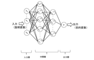
- FIG. 13 is a schematic diagram illustrating an example of an approximation model.
- FIG. 2 is a block diagram showing a configuration of a material property prediction unit.
- FIG. 2 is a schematic diagram of an example showing a mesh area for which the approximate model calculator calculates material properties.
- 11 is a schematic diagram showing an example of an output from a material characteristic output unit.
- FIG. FIG. 11 is a block diagram showing a configuration of a material property prediction unit in embodiment 2.
- 13 is a schematic diagram showing a correction method in a material characteristic correction unit in embodiment 2.
- FIG. 1 is a diagram showing an example of a hot sheet rolling line (hereinafter also referred to as a "rolling line") to which a material property prediction device for a rolled product (hereinafter also referred to as a "prediction device”) according to embodiment 1 is applied.
- a prediction device for predicting material properties of a rolled product manufactured in the rolling line shown in Fig. 1 will be described, but the prediction device of the present disclosure can also be applied to other rolling lines.
- the rolling line is equipped with a heating device, a rolling mill, a cooling device, a down coiler, and a conveying table connecting these. These devices are driven by actuators such as electric motors and hydraulic devices.
- the rolling line 1 shown in FIG. 1 is equipped with, from the upstream side of the conveying table, a heating furnace 2, a high-pressure descaling device 3, a rough entry thermometer 4, a rough edger 5, a rough horizontal rolling mill (hereinafter also referred to as the "rough rolling mill") 6, a rough exit thermometer 7, an edge heater 8, a bar heater 9, a finishing entry thermometer 10, a crop shear 11, a finishing entry descaling device 12, an F1 edger 13, a finishing rolling mill 14, a multi-gauge 15, a finishing exit thermometer 16, a run-out table 17, a coiler entry thermometer 18, and a down coiler 19.
- the heating furnace 2 is a furnace for heating the material to be rolled (slab), and is controlled to obtain the desired slab heating pattern and heating furnace extraction temperature.
- the material to be rolled includes not only slabs and steel plates, but also intermediate states until the material is completed as a product coil.
- the high-pressure descaling device 3 removes scale from the surface of the material to be rolled by spraying high-pressure water from above and below the material to be rolled that has left the heating furnace 2.
- the rough entry side thermometer 4 is disposed on the entry side (upstream side) of the rough rolling mill 6, and measures the rough entry side temperature, which is the temperature of the surface (e.g., the top surface) of the central part in the width direction of the material to be rolled.
- the rough edger 5 rolls the material to be rolled in the plate width direction.
- the rough rolling mill 6 rough rolls the steel plate in the plate thickness direction.
- the material to be rolled is rolled in multiple passes to make it the desired thickness. For this reason, a reversible rolling mill can be used as the rough rolling mill 6.
- the rough exit side thermometer 7 measures the temperature of the surface (e.g., the top surface) of the material being rolled.
- the rough exit side thermometer 5 is placed on the exit side (downstream side) of the rough rolling mill 6.
- the rough exit side thermometer 7 measures the surface temperature of the center in the width direction as the rough exit side temperature.
- the edge heater 8 is a device that heats the widthwise end (edge) of the rolled material by electromagnetic induction heating or the like in order to control the temperature of the rolled material.
- the bar heater 9 is a device that heats the entire rolled material by electromagnetic induction heating or the like in order to control the temperature of the rolled material.
- the finishing entry thermometer 10 is arranged on the entry side of the finishing rolling mill 14 and measures the finishing entry temperature, which is the temperature of the surface (e.g., the top surface) of the central part of the widthwise direction of the rolled material.
- the crop shear 11 cuts off the leading and trailing ends of the steel plate.
- the finishing entry descaling device 12 removes scale from the surface of the steel plate at the entry side of the finishing rolling mill 14.
- the F1 edger 13 is arranged on the entry side of the finishing rolling mill 14 and its rollers come into contact with the rolled material from the side.
- the F1 edger 13 deforms the rolled material to a degree that does not cause buckling so that the width of the rolled material narrows.
- the finishing rolling mill 14 consists of one or more stands, and in the example shown in FIG. 1, it is a tandem finishing rolling mill consisting of seven stands.
- the finishing rolling mill 14 finishes rolling the rolled material to a specified plate thickness.
- the multi-gauge 15 is a composite measuring instrument capable of performing various measurements with a single device.
- the multi-gauge 15 has, for example, a configuration in which multiple X-ray detectors are arranged in the width direction of the rolled material.
- the multi-gauge 15 measures, for example, the thickness distribution in the width direction of the rolled material.
- the multi-gauge 15 is equipped with a thermometer and a scan pyrometer inside. The multi-gauge 15 measures the temperature of the rolled material and uses the measurement value to correct the detection value of the X-ray detector.
- the finishing exit thermometer 16 measures the temperature of the surface (e.g., the top surface) of the rolled material.
- the finishing exit thermometer 16 is placed on the exit side (downstream side) of the finishing rolling mill 14.
- the finishing exit thermometer 16 measures the surface temperature of the center in the width direction of the rolled material that has passed through the finishing rolling mill 14 as the finishing exit temperature.
- the finishing exit thermometer 12 is placed on the exit side of the finishing rolling mill 10.
- the finishing exit temperature of the rolled material is closely related to the formation of the metal structure and material properties (tensile strength, yield stress, elongation, etc.) of the product. For this reason, the finishing exit temperature of the rolled material needs to be properly managed.
- the run-out table 17 is a cooling device that cools the rolled material with cooling water to control the temperature of the rolled product.
- the run-out table 17 supplies cooling water from nozzles to the surface of the rolled material to control the temperature of the rolled material.
- the run-out table 17 is equipped with many nozzles in the longitudinal direction of the rolled material (the conveying direction of the conveying table). These nozzles are divided into multiple banks. The nozzles are controlled for each bank, and the cooling speed of the rolled material is controlled. Water cooling is performed in the bank that supplies cooling water, and air cooling is performed in the bank to which cooling water is not supplied.
- the rolling line may further be equipped with a cooling device such as a cooling table or a forced cooling device.
- the coiler entry thermometer 18 is placed on the entry side (upstream side) of the down coiler 19. After the material to be rolled passes through the run-out table 17, the coiler entry thermometer 18 measures the surface temperature of the central part in the width direction as the coiling temperature.
- the finish exit thermometer 12 is placed on the exit side of the finishing rolling mill 10.
- the coiling temperature of the material to be rolled is closely related to the formation of the metal structure of the product and its material properties (tensile strength, yield stress, elongation, etc.). For this reason, the coiling temperature of the material to be rolled needs to be properly managed.
- the down coiler 19 is a device that winds up the rolled product and shapes it into a shape that is easy to transport.
- the transport table is a device that transports the rolled product at each process to the next process. These devices are driven by actuators such as electric motors and hydraulic devices.
- the rolling line 1 shown in FIG. 1 further includes a scan pyrometer 20.
- the scan pyrometer 20 measures the temperature of the surface (e.g., the top surface, or the top surface and bottom surface) of the rolled material at least at multiple locations in the width direction of the rolled material.
- the scan pyrometer 20 is preferably placed before and after a device for improving the temperature of the rolled material.
- the example shown in FIG. 1 shows a case where the scan pyrometer 20 is installed in front of the edge heater 8, behind the bar heater 9, and before and after the run-out table 17.
- the scan pyrometer 20 placed on the entry side of the run-out table 17 is provided inside the multi-gauge 15.
- [Rolling system] 2 is a block diagram showing a rolling system 21 according to the first embodiment.
- the rolling system 21 is a control system for the rolling line 1, and has a hierarchical structure from level 0 to level 3.
- Level 0 has a drive control device that controls an electric motor that drives each device of the rolling line 1, and hydraulic equipment (hydraulic device) that drives each device of the rolling line 1.
- Level 1 has a control controller 24.
- Level 2 has a setting computer 23.
- Level 3 has a host computer 22 for production management.
- a material property prediction device 25 of a rolled product which will be described later, is connected to the setting computer 23 and can receive rolling data.
- the hot rolling process different products are produced by changing the process conditions related to product quality and operating conditions, i.e., the target values of various process parameters.
- the process is controlled by the setting computer 23 so as to achieve the target product quality, i.e., so as to achieve the target values of the various process parameters mentioned above.
- the target values of the process parameters may be specified by a level 3 host computer 22, which is above the level 2 setting computer 23.
- the target values of the process parameters may have a table in a database belonging to the setting computer 23, and may be specified using the steel type, plate thickness, plate width, etc. as keys.
- the target values of the process parameters may be changed during rolling by manual intervention of the operator.
- the setting calculator 23 has model formulas that represent the physical phenomena of each process, such as heating, rolling, cooling, and transport, in the rolling line 1. Using the model formulas that represent the physical phenomena of the processes, the setting calculator 23 performs setting calculations so as to achieve the target values (process conditions) of the various process parameters mentioned above in actual operation. In the setting calculations, it repeatedly calculates the control target values of the various actuators and the state of the rolled material at each stage of the process (predicted state value of the metal material).
- the control target values of the actuators are the roll gap of the rolling mills 6 and 14, the rolling speed, the conveying speed, the flow rates of the descaler and various sprays, the ON/OFF state of the valves on the run-out table, etc.
- the state of the rolled material at each stage of the process is the dimensions, shape, temperature, microstructure, etc.
- the control controller 24 receives the setting calculation results from the setting calculator 23 and controls various actuators so as to follow the control target values.
- various sensors are installed throughout the rolling line 1 to monitor and collect the actual values of parameters that affect process control, such as temperature, shape, plate thickness, plate width, and rolling load.
- the target values of the process parameters are compared with actual values acquired by various sensors, and actual calculated values recalculated by the setting calculator 23 from the actual values and calculated values, and if the target values of the process parameters are not achieved, the setting calculator 23 performs the setting calculation again. Based on the results, various types of control, such as feedforward control, feedback control, and dynamic control, are performed.
- the adjustment terms are the coefficients and constants for each term in the model formula, and are managed in a database belonging to the setting computer 23 for each stratification using a stratification table divided by factors that are likely to cause model errors, such as steel type, target plate thickness, target plate width, and target temperature.
- the adjustment terms are adjusted mainly when rolling a new steel type or when rolling with a new combination of process parameters, other than when starting up operations.
- the adjustment terms may be adjusted by engineers based on experience or numerical analysis results, or in recent years, they may be semi-automatically adjusted using statistical methods such as neural networks.
- the learning terms are terms that are multiplied and added to the model formula to fill in the error between the model output and the output of the actual process.
- FIG. 3 is a block diagram showing the functions of a material property prediction device 25 for a rolled product according to embodiment 1.
- the prediction device 25 predicts the mechanical properties of a product coil rolled in the rolling line 1 shown in Fig. 1.
- the prediction device 25 includes an approximate model creation unit 26 and a material property prediction unit 27.
- FIG. 4 is a diagram showing an example of the hardware configuration of the prediction device 25.
- Each function of the prediction device 25 described below can be realized by a processing circuit 250 shown in FIG. 4.
- This processing circuit 250 may be dedicated hardware 251.
- This processing circuit may include a processor 252 and a memory 253.
- This processing circuit may be partially formed as dedicated hardware 251, and further include a processor 252 and a memory 253.
- a portion of the processing circuit 250 is formed as dedicated hardware 251, and the processing circuit 250 also includes a processor 252 and a memory 253.
- the processing circuitry 250 may be at least one dedicated hardware 251.
- the processing circuitry 250 may be, for example, a single circuit, a composite circuit, a programmed processor, a parallel programmed processor, an ASIC, an FPGA, or a combination of these.
- the processing circuit 250 may include at least one processor 252 and at least one memory 253.
- each function of the prediction device 25 is realized by software, firmware, or a combination of software and firmware.
- the software and firmware are written as a program and stored in the memory 253.
- the processor 252 realizes the functions of the approximation model creation unit 26 and the material property prediction unit 27 by reading and executing the program stored in the memory 253.
- the processor 252 is also called a CPU (Central Processing Unit), central processing unit, processing unit, arithmetic unit, microprocessor, microcomputer, and DSP.
- the memory 253 is, for example, a non-volatile or volatile semiconductor memory such as a RAM, ROM, flash memory, EPROM, and EEPROM. In this way, the processing circuit 250 can realize each function of the prediction device 25 by hardware, software, firmware, or a combination of these.
- the approximation model creation unit 26 creates an approximation model 39 that comprehensively and quickly predicts the mechanical properties of the hot rolled products manufactured on the rolling line 1, i.e., the rolled products (product coils) of all steel types, dimensions, and operating conditions that can be manufactured on the rolling line 1.
- the approximation model creation unit 26 creates an approximation model 39 that comprehensively and quickly predicts the mechanical properties of the hot rolled products manufactured on the rolling line 1, i.e., the rolled products (product coils) of all steel types, dimensions, and operating conditions that can be manufactured on the rolling line 1.
- Comprehensive means that it not only covers the mechanical properties of rolled products that have been manufactured on the rolling line 1, but also covers the mechanical properties of rolled products that may be manufactured on the rolling line 1 in the future. The details of the approximation model creation unit 26 are explained below.
- FIG. 5 is a block diagram showing the configuration of the approximation model creation unit 26.
- the approximation model creation unit 26 includes a dataset creation unit 28 and a model parameter determination unit 29.
- the dataset creation unit 28 creates a dataset used to create the approximation model 39.
- the model parameter determination unit 29 uses the dataset created by the dataset creation unit 28 to determine parameters that represent the approximation model 39 by an optimization method or the like.
- the data set 36 created by the data set creation unit 28 is a collection of data in which data on explanatory variables 37 and data on objective variables 38 are paired. Each pair is composed of data on explanatory variables 37 corresponding to a part of a certain operating condition and data on objective variables 38 corresponding to the mechanical properties of the coil manufactured by the rolling line 1 under that operating condition.
- first operating conditions operating conditions that are particularly correlated with the mechanical properties
- the content of chemical components in steel is adjusted to create different steel types.
- Chemical components that contribute to mechanical properties are included in the explanatory variables 37. Temperature conditions are adjusted to create different steel types, like chemical components, and have a large contribution to mechanical properties.
- the temperature history of a certain part of the product coil is time-series data, but when it is given as the explanatory variable 37, one-dimensional data obtained by instantaneously cutting out the time-series data at a necessary point is given.
- Temperature conditions that may cause variations for each product are used as the explanatory variables 37.
- temperature conditions that differ in the rolling direction and width direction such as the finish rolling exit temperature and the coiling temperature, and temperature conditions that cause a temperature drop at the width end, such as the rough rolling entry temperature and the rough rolling exit temperature, are also included as explanatory variables 37.
- mechanical properties are created by adjusting the temperature path according to the cooling conditions in the run-out table 17. Specifically, in addition to the target temperatures of the finish exit temperature and the coiling temperature, some of the cooling pattern conditions, such as the water-cooled part location, water-cooling speed, water-cooling time, and air-cooling time, are set and controlled (normal cooling).
- the run-out table 17 is divided into a front half and a rear half, an intermediate thermometer is installed at the midpoint, and in addition to the above target temperatures, the target temperature of the intermediate thermometer and the cooling pattern conditions for each of the front half and rear half of the run-out table 17 may be set and controlled (step cooling). Therefore, the cooling pattern conditions described later are also added to the explanatory variables.
- the processing conditions are operating conditions such as the reduction rate and strain rate of each stand. It is known that the reduction rate and strain rate affect the microstructure, and as a result, the final mechanical properties. They are added to the explanatory variables as processing conditions for each stand.
- the explanatory variables may be added to the explanatory variables as aggregate information such as the average of the entire finish rolling or the average of the latter half of the finish rolling stand.
- the time conditions such as the furnace time for slab material in the heating furnace, and the time between rough rolling and the start of finish rolling, vary from product to product, and by adding conditions that affect the mechanical properties to the explanatory variables, the prediction performance of the variation of the mechanical properties for each product may be improved.
- speed conditions such as the rolling speed and conveying speed at each point, which change from the front end to the tail end in the rolling direction and affect the mechanical properties, in the explanatory variables, the prediction performance of the variation of the mechanical properties within the product may be improved.
- the mechanical properties that are the objective variables are yield stress, tensile strength, elongation, etc.
- the data set 36 comprehensively includes the operating conditions at all locations, including the longitudinal leading end, tail end, and widthwise ends, of coils of all steel types and dimensions produced on the rolling line 1, and the mechanical properties when rolled under those operating conditions.
- FIG. 7 is a schematic diagram for explaining an example of the cooling pattern of the explanatory variable 37.
- FIG. 7 shows an example of a cooling pattern of normal cooling.
- the upstream bank of the run-out table 17 is used for feedforward control using the initial cooling setting by setting calculation and the actual finishing temperature value.
- the two most downstream banks are used for feedback control using the actual winding temperature, and the bank upstream of the bank used for feedback control is used for dynamic control to follow the change in the conveying speed.
- the water-cooling section cooling speed, the water-cooling section cooling speed of the front half, the water-cooling section cooling speed of the rear half, the average cooling speed of the front half, the average cooling speed of the rear half, and the water-cooling section cooling speed of the feedback bank are used as explanatory variables.
- the water-cooling section cooling speed V cool is calculated by the following formula (1) with respect to the temperature drop due to water cooling in the banks excluding the dynamic control bank and the feedback control bank.
- t W_s is the start time of water cooling excluding the dynamic control bank and the feedback control bank
- t W_e is the end time of water cooling excluding the dynamic control bank and the feedback control bank
- T W_s is the temperature at the start of water cooling
- T W_e is the temperature at the end of water cooling.
- cooling in the front and rear sections of the run-out table 17 has different effects on mechanical properties.
- the cooling rate of the water-cooled section in the front and rear sections, the average cooling rate in the front and rear sections, etc. are calculated and used as explanatory variables.
- the cooling rate of the water-cooled section in the front section, V E_cool targets the temperature drop due to water cooling in the bank between the finish delivery temperature and the intermediate temperature, and is calculated using the following formula (2).
- t E_s is the time when water cooling of the first bank starts
- t E_e is the time when water cooling of the first bank ends
- T E_s is the temperature when water cooling of the first bank starts
- T E_e is the temperature when water cooling of the first bank ends.
- the cooling rate of the water-cooled part in the latter half is also included in the explanatory variables by calculating it using the time and temperature information of the latter half.
- the average cooling rate V E_ave in the first half targets the temperature drop by water cooling and air cooling in the bank between the finish exit temperature and the intermediate temperature, and is calculated by the following formula (3).
- t FDT is the finishing outlet temperature passing time
- t MT is the intermediate temperature passing time
- T FDT is the finishing outlet temperature
- T MT is the intermediate temperature.
- the average cooling rate in the latter half is also included in the explanatory variables by calculating it using the time and temperature information in the latter half.
- the cooling pattern by the feedback bank varies in the rolling direction of the rolled material due to feedback control for controlling the coiling temperature, which may affect the mechanical properties.
- the cooling rate of the water-cooled part of the feedback bank is added to the explanatory variables.
- the cooling rate of the water-cooled part of the feedback bank VFB_cool is calculated by the following formula (4), targeting the water-cooled part of the feedback bank.
- t FB — s is the feedback bank water cooling start time
- t FB — e is the feedback bank water cooling end time
- T FB — s is the feedback bank water cooling start temperature
- T FB — e is the feedback bank water cooling start temperature
- FIG. 8 is a diagram for explaining the configuration of the data set creation unit 28 and the creation of a data set.
- the data set creation unit 28 includes a condition setting unit 30 and a material calculation unit 31.
- the condition setting unit 30 sets the first operating conditions related to the explanatory variables 37 of the data set 36.
- the condition setting unit 30 also sets the operating conditions such as chemical components, processing history, and temperature history required for metal structure calculation using the metallurgical phenomenon model in the metal structure calculation unit 44 in the material calculation unit 31 (hereinafter, the operating conditions related to the input of the metallurgical phenomenon model used by the metal structure calculation unit 44 are referred to as "second operating conditions").
- the first operating conditions and the second operating conditions include the same data, but also different data.
- the metallurgical phenomenon model predicts changes in the microstructure from moment to moment. Therefore, the second operating conditions include data that has spatial and temporal continuity at each equipment position and each time, such as processing history and temperature history.
- the material calculation unit 31 calculates metallurgical phenomena and mechanical properties based on the set second operating conditions. In addition, the material calculation unit 31 sets data for the objective variable 38 of the data set 36.
- FIG. 9 is a diagram for explaining the setting of the material calculation unit 31 and explanatory variables 37 by the condition setting unit 30.
- the condition setting unit 30 is composed of, for example, an operating condition extraction unit 40, an operating condition creation unit 41, a material calculation input setting unit 42, and an explanatory variable setting unit 43.
- the operating condition extraction unit 40 extracts, for example, the first operating conditions related to the above-mentioned explanatory variables 37 such as chemical components, processing history, and temperature history, and the second operating conditions used in the material calculation unit 31, from the virtual rolling data of a virtual coil virtually rolled by an offline setting computer.
- the offline setting calculator described above is, for example, a device such as that described in Patent Document 1, and can simulate actual operations by synchronizing process parameters with the online setting calculator. This makes it possible to create a variety of operating conditions through offline setting calculations without placing a burden on actual operations. For example, even for products and rolling conditions that have never been manufactured in actual operations, it is possible to simulate operations that satisfy various machine constraints.
- the operating conditions and explanatory variables 37 used in the material calculation unit 31 may include operating conditions and explanatory variables 37 extracted from actual rolling data of the product coil that was actually rolled.
- operating conditions such as processing history and temperature history, such as distortion of each part in the product, may be created using analysis data that is more detailed than the set calculation, such as the results of finite element analysis.
- the operating conditions to which the approximation model 39 can be applied should include disturbances that are not measured or calculated in actual operation.
- disturbances include variations in chemical composition, uneven temperatures during reheating in the heating furnace, an unexpected drop in the temperature of the rolled material due to oscillation before finish rolling, and an inability to ensure the cooling rate due to spray problems.
- the disturbances are simulated using the offline setting calculator described above. Alternatively, disturbances may be added directly to the processing history or temperature history of the actual rolling data or virtual rolling data.
- the operating condition creation unit 41 intentionally makes changes to simulate disturbances in part of the rolling data created by duplicating the actual rolling data and virtual rolling data.
- the material calculation input setting unit 42 passes to the material calculation unit 31 the operating conditions extracted by the operating condition extraction unit 40, or the operating conditions extracted by the operating condition extraction unit 40 with modifications made by the operating condition creation unit 41 corresponding to disturbances, or the operating conditions created by the operating condition creation unit 41 from external data such as finite element analysis results without going through the operating condition extraction unit 40.
- the explanatory variable setting unit 43 extracts data corresponding to the explanatory variables 37 from the operating conditions extracted by the operating condition extraction unit 40, or the operating conditions extracted by the operating condition extraction unit 40 with changes corresponding to disturbances made by the operating condition creation unit 41, or the operating conditions created by the operating condition creation unit 41 without going through the operating condition extraction unit 40, and adds the data to the dataset 36 as explanatory variables 37.
- FIG. 10 is a diagram for explaining the metallurgical phenomenon calculation by the material calculation unit 31 and the setting of the objective variable 38.
- the material calculation unit 31 is composed of a metal structure calculation unit 44, a material property calculation unit 45, and an objective variable setting unit 46.
- the metal structure calculation unit 44 calculates the metal structure with a metallurgical phenomenon model that mathematically expresses metallurgical phenomena, using rolling data such as chemical components, processing history, and temperature history set in the material calculation input setting unit 42 of the condition setting unit 11.
- the characteristics of the metal structure to be calculated include the volume fractions of ferrite, pearlite, bainite, and martensite, and the grain sizes of ferrite and austenite.
- Various metallurgical phenomenon models have been proposed, and are composed of a group of formulas that represent static recovery, static recrystallization, dynamic recovery, dynamic recrystallization, grain growth, and transformation. An example of this model is published on pages 198 to 229 of Plastic Processing Technology Series 7, Plate Rolling (Corona Co., Ltd.).
- the material property calculation unit 45 calculates mechanical properties based on the chemical components and the like contained in the rolling data described above and the metal structure calculation value obtained from the metal structure calculation unit 44.
- the mechanical properties to be measured include yield stress, tensile strength, elongation, and the like.
- the model is often automatically learned at any time using the actual values of mechanical properties obtained from the results of mechanical property measurement tests such as tensile tests performed on some product coils (for example, the method of Patent Document 4).
- the actual measured mechanical property values are measured on test pieces cut out from a part of the coil, such as the tip or tail end of the coil.
- the actual measured values of the changes in mechanical properties due to differences in operating conditions such as the temperature in the rolling direction and the plate width direction described above cannot be obtained, and are not reflected in the learning of the metallurgical phenomenon model.
- the mechanical property prediction results of the metallurgical phenomenon model including learning become specific values, and the change in the mechanical property prediction results with respect to changes in operating conditions becomes less smooth.
- the material property calculation unit 45 uses a metallurgical phenomenon model that does not involve learning, rather than a metallurgical phenomenon model that is automatically learned during actual operation.
- the objective variable setting unit 46 extracts data corresponding to the objective variable 20 from the mechanical properties created by the material property calculation unit 45, and adds it to the data set 36 as the objective variable 20 that is paired with the explanatory variable 37 created from the operating conditions used by the material calculation unit 12.
- FIG. 11 is a schematic diagram showing an example of an approximation model.
- a machine learning model can be used as the approximation model 39.
- the machine learning model is constructed by a forward propagation type neural network consisting of an input layer, an intermediate layer, and an output layer.
- Explanatory variables 37 which are operating conditions, are input to the input layer.
- the model parameter determination unit 29 determines the hyperparameters and parameters of the forward propagation neural network.
- the hyperparameters include the network configuration (number of layers in the intermediate layer, number of units), the type of activation function, etc.
- the hyperparameters are determined empirically or by trial and error. Alternatively, they are determined by methods commonly used in recent years, such as grid search and Bayesian optimization.
- the parameters are the weight coefficients and biases of each unit that express the function of the forward propagation neural network.
- the input and output pairs are called training data. Parameters are selected so that the output of the neural network when the input (explanatory variable) of the training data is given to the function is as close as possible to the output (objective variable) of the training data.
- the explanatory variable 37 of the dataset 36 created by the dataset creation unit 28 is used as the input, the objective variable 20 is used as the output, and the parameters are adjusted using the pair of the explanatory variable 37 and the objective variable 20.
- a part of the pairs in the data set for example, about 70% of the whole, is used as training data.
- An error function expressed by squared error or the like is used as a measure of the reproducibility of the function expressed by the neural network.
- the neural network is learned by solving the minimization problem of the error function.
- gradient descent and its improved method, Adam are known as optimization methods for solving the above-mentioned minimization problem of the error function.
- the model parameter determination unit 29 uses Adam to learn the forward propagation type neural network.
- the parameters may be adjusted again after making efforts generally made in constructing a machine learning model, such as changing hyperparameters, increasing the number of data pairs in the data set, and reviewing data preprocessing.
- the model may be sequentially learned using gradient descent or the like. This is the case when online rolling data is obtained at any time, or when offline setting calculations are performed at any time.
- a data set can be recreated using the latest data, and the approximation model can be reconstructed and replaced. It is also possible to change the type of explanatory variables depending on the type of mechanical property to be predicted. It is preferable to create a different approximation model for each mechanical property.
- the material property prediction unit 27 predicts online the mechanical properties of each three-dimensional mesh area of the product coil actually manufactured on the rolling line 1 using an approximation model 39 that is created in advance offline by the approximation model creation unit 26.
- FIG. 12 is a block diagram showing the configuration of the material property prediction unit 27.
- the material property prediction unit 27 includes a rolling data collection unit 32, a model input creation unit 33, an approximation model calculation unit 34, and a material property output unit 35.
- the rolling data collection unit 32 collects rolling data for each part of the coil from the heating furnace to winding.
- the model input creation unit 33 creates input data for the approximation model 39 from the rolling data collected by the rolling data collection unit 32.
- the approximation model calculation unit 34 calculates the mechanical properties of each three-dimensional mesh-like area of the product coil using the input data created by the model input creation unit 33 and the approximation model 39.
- the material property output unit 35 outputs the mechanical properties calculated by the approximation model calculation unit 34 together with information indicating the position within the product.
- the rolling data collection unit 13 collects rolling data such as the chemical composition, processing history, and temperature history of the product coil calculated by the setting calculator 23.
- the rolling data is a predicted value before rolling, a predicted value and recalculated actual values during rolling, and recalculated actual values after rolling, and the accuracy of the information differs depending on the timing of acquisition.
- the model input creation unit 33 extracts data corresponding to explanatory variables 37 of each three-dimensional mesh-like area of the product coil from the rolling data of the product coil collected by the rolling data collection unit 13 as input data for the approximation model 39. If the rolling data collected by the rolling data collection unit 13 is insufficient to create explanatory variables 37 of each three-dimensional mesh-like area, the explanatory variables 37 are created by supplementing the missing data. For example, in recent years, the temperature distribution in the thickness and width directions of the rolled material may be calculated from actual measurements taken with a thermometer and model predictions, but due to the calculation load, the setting calculator 23 may intentionally limit the calculation range by calculating the width direction temperature distribution up to the edge heater exit side required for control and stopping calculation downstream of the edge heater.
- the rolling data collection unit 13 uses the actual value of the width direction temperature distribution measured by the multi-gauge at the downstream side of the finishing rolling mill, the width direction temperature distribution at the edge heater exit side calculated by the model or the actual width direction temperature distribution by the scan pyrometer at the edge heater exit side, and the temperature history calculation result of the width direction center part at the edge heater exit side to the finish rolling mill exit side to create explanatory variable 37 data related to the temperature of each mesh in the width direction, for example, the finish rolling entry side temperature, using an interpolation formula such as linear interpolation.
- the width direction temperature distribution may be calculated using an offline setting calculator.
- a part of the processing history such as the strain rate during rolling in the thickness direction is generally not performed in the width direction.
- the contact length of the deformation region between the roll and the material is considerably shorter than the width of the material, the movement of the material in the width direction is small, and the thickness reduction is mainly elongation in the rolling direction.
- the data calculated in the width direction center part can be duplicated in the width direction and used as explanatory variable 37. Additionally, for data where only one value can be obtained for a product coil, such as chemical composition, the same value is used for all meshes.
- the approximation model calculation unit 34 inputs the input data created by the model input creation unit 33 into the approximation model 39 created in advance by the approximation model creation unit 26, and calculates the mechanical properties of each area of the three-dimensional mesh of the product coil.
- Figure 13 is a schematic diagram of an example of a mesh area for which the approximation model calculation unit 34 calculates material properties.
- Figure 13 shows only a portion of the overall length and one half of the plate width direction (work side or drive side), but the approximation model calculation unit 34 calculates the overall length and overall width.
- the calculation interval set in the rolling direction may differ depending on the product plate thickness, but for example, rolling data is created at 2 m intervals, and mechanical properties are predicted at similar intervals.
- mechanical properties are predicted at three points: the top surface, the plate thickness center, and the bottom surface.
- width direction mechanical properties are predicted at a total of five points: a point 40 mm from the width end (work side and drive side), a midpoint between the width end and the plate width center (plate width 1/4 point) (work side and drive side), and the plate width center.
- the material property output unit 35 outputs the mechanical properties of each zone calculated by the approximation model calculation unit 34, information representing the position of each zone in the rolled product, and information closely related to the variation of mechanical properties.
- the position of each zone in the rolled product is the distance from the leading edge in the rolling direction, the distance from the tail end, the position in the width direction, and the position in the plate thickness direction.
- the information related to the mechanical properties is information closely related to the variation of mechanical properties, such as the finishing exit temperature, the coiling temperature, and the cooling rate.
- the output destination is a storage device such as a database and a visualization device such as an HMI. When outputting to a visualization device, the output data is visualized in a graph, or values are shown in a table or the like.
- FIG. 14 is a schematic diagram showing an example of the output of the material characteristic output unit 35.
- the horizontal axis shows the rolling direction position (distance from the tip), and the vertical axis shows the change in tensile strength and coiling temperature.
- the positions in the plate thickness direction and width direction can be selected arbitrarily, and in this example, the plate thickness center and the work side 1/4 point in the width direction are selected.
- the lower limit of tensile strength is given, information such as the position of the rolled material where the tensile strength is below the lower limit and the relationship with the coiling temperature can be obtained.
- the distribution of mechanical properties of the entire product may be visualized in a three-dimensional mesh-like heat map.
- Information visualized in the table includes, for example, the position information of the mechanical properties not achieved (distance from the tip and tail), basic statistics such as the average value and standard deviation of the mechanical properties, and the correlation coefficient between the mechanical properties and the explanatory variables 37.
- a data set corresponding to rolling conditions (temperature conditions, processing conditions, time/speed conditions) that have not been implemented in an actual rolling process or rolling conditions with little experience are comprehensively created in advance.
- an approximation model offline using a data set created to cover all rolling conditions including rolling conditions that have not been implemented or have little experience, it is possible to create an approximation model that can handle the entire group of rolled products and has high approximation accuracy.
- the approximation model created in this way it is possible to reduce the calculation load for online prediction of material properties in each area of a three-dimensional mesh of any rolled product.
- Embodiment 2 Next, a second embodiment of the present invention will be described with reference to Figures 15 and 16. The differences from the first embodiment will be mainly described, and the same or corresponding parts will be denoted by the same reference numerals and description thereof will be omitted.
- FIG. 15 is a block diagram showing the configuration of the material property prediction unit 27 according to the second embodiment.
- the mechanical property prediction unit 27 as the material property prediction unit includes a material property correction unit 47 that corrects the mechanical property (hereinafter referred to as the "first mechanical property") calculated by the approximation model calculation unit 34 using the approximation model 39, using the mechanical property (hereinafter referred to as the "second mechanical property") calculated by a metallurgical phenomenon model that mathematically represents a metallurgical phenomenon.
- the metallurgical phenomenon model that mathematically represents a metallurgical phenomenon and predicts the second mechanical property is model-trained using actual mechanical property values obtained in tensile tests of past rolled products (product coils).
- the second mechanical property is collected by the rolling data collection unit 13 from the online setting computer 23 as part of the rolling data.
- the mechanical properties of a part of a rolled product may be calculated using a metallurgical phenomenon model in which metallurgical phenomena are mathematically formulated by an online setting computer or a computer connected to the online setting computer.
- the metallurgical phenomenon model in which metallurgical phenomena are mathematically formulated is model trained using actual values of mechanical properties obtained from the results of mechanical property measurement tests such as tensile tests and structure observations performed on some product coils, or is adjusted to match the actual mechanical properties (for example, the method of Patent Document 4). It is expected that the prediction accuracy of the predicted second mechanical property that is learned or adjusted in this way is good.
- ⁇ TS(j) TS MM (j)- TS ML (j)...(5)
- j is an index indicating the mesh area from which the second mechanical property was obtained
- TS MM (j) is the second mechanical property contained in the actual rolling data
- TS ML (j) is the first mechanical property calculated by the approximate model calculation unit 34
- ⁇ TS(j) is the difference between the second mechanical property and the first mechanical property.
- FIG. 15 is a schematic diagram showing a correction method in the material property correction unit 47 in the second embodiment of the present invention.
- the difference ⁇ TS(i) between the second mechanical property and the first mechanical property assumed in other mesh areas i is calculated by linear interpolation or the like using ⁇ TS(j) at the above three points.
- TS comp (i) TS ML (i) + ⁇ TS(i)...(6)
- i is an index indicating the mesh area for which the tensile strength is to be corrected
- TS ML (i) is the tensile strength calculated by the approximation model calculation unit 34 using the approximation model 39
- TS comp (i) is the corrected tensile strength.
- the material property correction unit 47 since the material property correction unit 47 is provided, the prediction accuracy of the mechanical properties of all parts of the rolled product can be improved. Moreover, there is no effect on the online calculation of the actual rolling operation. Note that, although an example of predicting the mechanical properties of the material properties has been described above, the same applies to the electromagnetic properties.
Landscapes
- Engineering & Computer Science (AREA)
- Physics & Mathematics (AREA)
- General Physics & Mathematics (AREA)
- Business, Economics & Management (AREA)
- Theoretical Computer Science (AREA)
- Mechanical Engineering (AREA)
- General Engineering & Computer Science (AREA)
- Quality & Reliability (AREA)
- Strategic Management (AREA)
- Human Resources & Organizations (AREA)
- Economics (AREA)
- Software Systems (AREA)
- Automation & Control Theory (AREA)
- Manufacturing & Machinery (AREA)
- Artificial Intelligence (AREA)
- Data Mining & Analysis (AREA)
- Computing Systems (AREA)
- Development Economics (AREA)
- Medical Informatics (AREA)
- Game Theory and Decision Science (AREA)
- Evolutionary Computation (AREA)
- Mathematical Physics (AREA)
- Entrepreneurship & Innovation (AREA)
- Marketing (AREA)
- Operations Research (AREA)
- Tourism & Hospitality (AREA)
- General Business, Economics & Management (AREA)
- Computer Vision & Pattern Recognition (AREA)
- Control Of Metal Rolling (AREA)
Priority Applications (5)
| Application Number | Priority Date | Filing Date | Title |
|---|---|---|---|
| JP2024550631A JP7768418B2 (ja) | 2023-03-14 | 2023-03-14 | 圧延製品の材質特性予測装置 |
| US18/854,553 US20250355426A1 (en) | 2023-03-14 | 2023-03-14 | Material properties prediction device for rolled products |
| CN202380028593.XA CN118973725A (zh) | 2023-03-14 | 2023-03-14 | 轧制产品的材质特性预测装置 |
| KR1020247032107A KR20240157048A (ko) | 2023-03-14 | 2023-03-14 | 압연 제품의 재질 특성 예측 장치 |
| PCT/JP2023/009919 WO2024189790A1 (ja) | 2023-03-14 | 2023-03-14 | 圧延製品の材質特性予測装置 |
Applications Claiming Priority (1)
| Application Number | Priority Date | Filing Date | Title |
|---|---|---|---|
| PCT/JP2023/009919 WO2024189790A1 (ja) | 2023-03-14 | 2023-03-14 | 圧延製品の材質特性予測装置 |
Publications (1)
| Publication Number | Publication Date |
|---|---|
| WO2024189790A1 true WO2024189790A1 (ja) | 2024-09-19 |
Family
ID=92754726
Family Applications (1)
| Application Number | Title | Priority Date | Filing Date |
|---|---|---|---|
| PCT/JP2023/009919 Ceased WO2024189790A1 (ja) | 2023-03-14 | 2023-03-14 | 圧延製品の材質特性予測装置 |
Country Status (5)
| Country | Link |
|---|---|
| US (1) | US20250355426A1 (https=) |
| JP (1) | JP7768418B2 (https=) |
| KR (1) | KR20240157048A (https=) |
| CN (1) | CN118973725A (https=) |
| WO (1) | WO2024189790A1 (https=) |
Citations (5)
| Publication number | Priority date | Publication date | Assignee | Title |
|---|---|---|---|---|
| JP2001025805A (ja) * | 1999-07-13 | 2001-01-30 | Kobe Steel Ltd | 圧延シミュレーション装置,及び圧延シミュレーションプログラムを記録したコンピュータ読み取り可能な記録媒体 |
| JP2008168320A (ja) * | 2007-01-11 | 2008-07-24 | Toshiba Mitsubishi-Electric Industrial System Corp | 圧延ラインの組織・材質管理システム |
| JP2010172962A (ja) * | 2009-02-02 | 2010-08-12 | Toshiba Mitsubishi-Electric Industrial System Corp | 圧延製品の特性予測方法 |
| WO2016038705A1 (ja) * | 2014-09-10 | 2016-03-17 | 東芝三菱電機産業システム株式会社 | 圧延シミュレーション装置 |
| CN114417664A (zh) * | 2022-01-04 | 2022-04-29 | 大连理工大学 | 一种基于元胞自动机的钢材热轧微观组织演化在线模拟和可视化方法 |
Family Cites Families (9)
| Publication number | Priority date | Publication date | Assignee | Title |
|---|---|---|---|---|
| JPS5396889U (https=) | 1977-01-07 | 1978-08-07 | ||
| JPS6086155U (ja) | 1983-11-22 | 1985-06-13 | 共栄工業株式会社 | 家具類の転倒防止装置 |
| JPS6197676U (https=) | 1984-12-03 | 1986-06-23 | ||
| JPS6292309U (https=) | 1985-11-29 | 1987-06-12 | ||
| JPH0646903Y2 (ja) | 1987-09-17 | 1994-11-30 | 株式会社フジハンドリング | 多層階垂直搬送装置 |
| JP2005315703A (ja) | 2004-04-28 | 2005-11-10 | Nippon Steel Corp | 鋼材の材質予測方法 |
| JP6933070B2 (ja) | 2017-09-20 | 2021-09-08 | 日本製鉄株式会社 | 製品の特性の予測装置、方法、及びプログラム、並びに製造プロセスの制御システム |
| JP7052579B2 (ja) | 2018-06-13 | 2022-04-12 | 日本製鉄株式会社 | 板クラウン演算装置、板クラウン演算方法、コンピュータプログラム、及びコンピュータ読み取り可能な記憶媒体 |
| JP7314891B2 (ja) | 2020-09-14 | 2023-07-26 | Jfeスチール株式会社 | 鋼帯の製造方法 |
-
2023
- 2023-03-14 JP JP2024550631A patent/JP7768418B2/ja active Active
- 2023-03-14 CN CN202380028593.XA patent/CN118973725A/zh active Pending
- 2023-03-14 US US18/854,553 patent/US20250355426A1/en active Pending
- 2023-03-14 KR KR1020247032107A patent/KR20240157048A/ko active Pending
- 2023-03-14 WO PCT/JP2023/009919 patent/WO2024189790A1/ja not_active Ceased
Patent Citations (5)
| Publication number | Priority date | Publication date | Assignee | Title |
|---|---|---|---|---|
| JP2001025805A (ja) * | 1999-07-13 | 2001-01-30 | Kobe Steel Ltd | 圧延シミュレーション装置,及び圧延シミュレーションプログラムを記録したコンピュータ読み取り可能な記録媒体 |
| JP2008168320A (ja) * | 2007-01-11 | 2008-07-24 | Toshiba Mitsubishi-Electric Industrial System Corp | 圧延ラインの組織・材質管理システム |
| JP2010172962A (ja) * | 2009-02-02 | 2010-08-12 | Toshiba Mitsubishi-Electric Industrial System Corp | 圧延製品の特性予測方法 |
| WO2016038705A1 (ja) * | 2014-09-10 | 2016-03-17 | 東芝三菱電機産業システム株式会社 | 圧延シミュレーション装置 |
| CN114417664A (zh) * | 2022-01-04 | 2022-04-29 | 大连理工大学 | 一种基于元胞自动机的钢材热轧微观组织演化在线模拟和可视化方法 |
Also Published As
| Publication number | Publication date |
|---|---|
| CN118973725A (zh) | 2024-11-15 |
| KR20240157048A (ko) | 2024-10-31 |
| JP7768418B2 (ja) | 2025-11-12 |
| US20250355426A1 (en) | 2025-11-20 |
| JPWO2024189790A1 (https=) | 2024-09-19 |
Similar Documents
| Publication | Publication Date | Title |
|---|---|---|
| KR101889668B1 (ko) | 압연 시뮬레이션 장치 | |
| JP7020379B2 (ja) | 金属材料の材質制御支援装置 | |
| JP7298645B2 (ja) | 形鋼の断面寸法変化量予測モデルの生成方法、形鋼の断面寸法変化量予測モデルの生成装置、形鋼の断面寸法の予測方法、形鋼の断面寸法の制御方法、および形鋼の製造方法 | |
| JP5488140B2 (ja) | 品質予測装置、品質予測方法、コンピュータプログラム、およびコンピュータ読み取り可能な記録媒体 | |
| JP4744226B2 (ja) | 冷却制御モデルの学習方法及び圧延材の冷却方法。 | |
| JP2011221642A (ja) | 品質予測装置、品質予測方法、コンピュータプログラム、およびコンピュータ読み取り可能な記録媒体 | |
| US20240265302A1 (en) | Method for determining mechanical properties of a rolled material using a hybrid model | |
| JP4402502B2 (ja) | 巻取温度制御装置 | |
| JP6021450B2 (ja) | 加熱炉の操業支援システム | |
| JP5610869B2 (ja) | 圧延材の冷却制御方法、及びこの冷却制御方法が適用された連続圧延機 | |
| JP5003483B2 (ja) | 圧延ラインの材質予測および材質制御装置 | |
| JP7180796B2 (ja) | 物理モデル同定システム | |
| JP7135962B2 (ja) | 鋼板の仕上出側温度制御方法、鋼板の仕上出側温度制御装置、及び鋼板の製造方法 | |
| JP7768418B2 (ja) | 圧延製品の材質特性予測装置 | |
| JP7230880B2 (ja) | 圧延荷重予測方法、圧延方法、熱延鋼板の製造方法、及び圧延荷重予測モデルの生成方法 | |
| JP6900866B2 (ja) | 圧延スケジュール作成装置、圧延スケジュール作成方法、およびプログラム | |
| JP4696775B2 (ja) | 板幅制御方法および装置 | |
| KR20250150054A (ko) | 강 가공 라인의 모니터링 방법, 관련 전자 장치 및 강 가공 라인 | |
| JPWO2024189790A5 (https=) | ||
| Agarwal et al. | An on-line hierarchical decomposition based Bayesian model for quality prediction during hot strip rolling | |
| JP7841665B1 (ja) | 形鋼の冷間寸法予測方法、形鋼の製造方法、冷間寸法予測モデルの生成方法及び形鋼の冷間寸法予測装置 | |
| JP2021126684A (ja) | 圧延装置の制御装置、圧延装置の制御方法、及び圧延装置の制御プログラム | |
| WO2025134174A1 (ja) | 圧延制御装置 | |
| JP2024011327A (ja) | 予測装置、学習装置、予測プログラム、及び学習プログラム |
Legal Events
| Date | Code | Title | Description |
|---|---|---|---|
| WWE | Wipo information: entry into national phase |
Ref document number: 2024550631 Country of ref document: JP |
|
| WWE | Wipo information: entry into national phase |
Ref document number: 202417069922 Country of ref document: IN |
|
| WWE | Wipo information: entry into national phase |
Ref document number: 202380028593.X Country of ref document: CN |
|
| ENP | Entry into the national phase |
Ref document number: 20247032107 Country of ref document: KR Kind code of ref document: A |
|
| WWE | Wipo information: entry into national phase |
Ref document number: 1020247032107 Country of ref document: KR |
|
| WWE | Wipo information: entry into national phase |
Ref document number: 18854553 Country of ref document: US |
|
| 121 | Ep: the epo has been informed by wipo that ep was designated in this application |
Ref document number: 23927411 Country of ref document: EP Kind code of ref document: A1 |
|
| NENP | Non-entry into the national phase |
Ref country code: DE |
|
| WWP | Wipo information: published in national office |
Ref document number: 18854553 Country of ref document: US |
|
| 122 | Ep: pct application non-entry in european phase |
Ref document number: 23927411 Country of ref document: EP Kind code of ref document: A1 |