WO2024185854A1 - 液晶偏光干渉素子、および、フィルター - Google Patents
液晶偏光干渉素子、および、フィルター Download PDFInfo
- Publication number
- WO2024185854A1 WO2024185854A1 PCT/JP2024/008812 JP2024008812W WO2024185854A1 WO 2024185854 A1 WO2024185854 A1 WO 2024185854A1 JP 2024008812 W JP2024008812 W JP 2024008812W WO 2024185854 A1 WO2024185854 A1 WO 2024185854A1
- Authority
- WO
- WIPO (PCT)
- Prior art keywords
- liquid crystal
- crystal layer
- retardation
- layer
- horizontally aligned
- Prior art date
- Legal status (The legal status is an assumption and is not a legal conclusion. Google has not performed a legal analysis and makes no representation as to the accuracy of the status listed.)
- Ceased
Links
Images


Classifications
-
- G—PHYSICS
- G02—OPTICS
- G02B—OPTICAL ELEMENTS, SYSTEMS OR APPARATUS
- G02B5/00—Optical elements other than lenses
- G02B5/30—Polarising elements
- G02B5/3016—Polarising elements involving passive liquid crystal elements
-
- B—PERFORMING OPERATIONS; TRANSPORTING
- B32—LAYERED PRODUCTS
- B32B—LAYERED PRODUCTS, i.e. PRODUCTS BUILT-UP OF STRATA OF FLAT OR NON-FLAT, e.g. CELLULAR OR HONEYCOMB, FORM
- B32B7/00—Layered products characterised by the relation between layers; Layered products characterised by the relative orientation of features between layers, or by the relative values of a measurable parameter between layers, i.e. products comprising layers having different physical, chemical or physicochemical properties; Layered products characterised by the interconnection of layers
- B32B7/02—Physical, chemical or physicochemical properties
- B32B7/023—Optical properties
-
- B—PERFORMING OPERATIONS; TRANSPORTING
- B32—LAYERED PRODUCTS
- B32B—LAYERED PRODUCTS, i.e. PRODUCTS BUILT-UP OF STRATA OF FLAT OR NON-FLAT, e.g. CELLULAR OR HONEYCOMB, FORM
- B32B7/00—Layered products characterised by the relation between layers; Layered products characterised by the relative orientation of features between layers, or by the relative values of a measurable parameter between layers, i.e. products comprising layers having different physical, chemical or physicochemical properties; Layered products characterised by the interconnection of layers
- B32B7/03—Layered products characterised by the relation between layers; Layered products characterised by the relative orientation of features between layers, or by the relative values of a measurable parameter between layers, i.e. products comprising layers having different physical, chemical or physicochemical properties; Layered products characterised by the interconnection of layers with respect to the orientation of features
-
- B—PERFORMING OPERATIONS; TRANSPORTING
- B32—LAYERED PRODUCTS
- B32B—LAYERED PRODUCTS, i.e. PRODUCTS BUILT-UP OF STRATA OF FLAT OR NON-FLAT, e.g. CELLULAR OR HONEYCOMB, FORM
- B32B9/00—Layered products comprising a layer of a particular substance not covered by groups B32B11/00 - B32B29/00
-
- G—PHYSICS
- G02—OPTICS
- G02B—OPTICAL ELEMENTS, SYSTEMS OR APPARATUS
- G02B5/00—Optical elements other than lenses
- G02B5/20—Filters
-
- G—PHYSICS
- G02—OPTICS
- G02B—OPTICAL ELEMENTS, SYSTEMS OR APPARATUS
- G02B5/00—Optical elements other than lenses
- G02B5/20—Filters
- G02B5/28—Interference filters
-
- G—PHYSICS
- G02—OPTICS
- G02B—OPTICAL ELEMENTS, SYSTEMS OR APPARATUS
- G02B5/00—Optical elements other than lenses
- G02B5/30—Polarising elements
Definitions
- the present invention relates to a liquid crystal polarization interference element and a filter using the same.
- Bandpass filters which transmit light in a specific wavelength range and block light of other wavelengths, are used in various optical devices.
- bandpass filters include a polarizing interference filter using a dielectric multilayer film, and a filter combining a polarizing element and a birefringent crystal. Also known is a bandpass filter in which, as described in Patent Document 1, birefringent plates ( ⁇ /2 plates) of equal thickness and in which the angle between the transmission axis direction of the polarizer and the slow axis is + ⁇ and a birefringent plate in which the angle is ⁇ are alternately laminated between polarizers arranged in crossed Nicols.
- Patent Document 1 proposes an optical filter (bandpass filter) made of crystals with a small number of parts, in which the crystals have a structure in which two different types of polarization regions are arranged periodically, and the principal axis of an index ellipsoid cut parallel to the interface between the two different types of polarization regions is different in the two different types of polarization regions.
- bandpass filters The problem with such bandpass filters is that the wavelength at which light that is incident at an angle shows maximum transmittance is different from that of light that is incident from the front (perpendicular direction), resulting in a so-called shortwave shift.
- the objective of the present invention is to solve the problems of the conventional technology and to provide a liquid crystal polarization interference element that, when used in a bandpass filter or the like, is unlikely to cause a shift in the wavelength of maximum transmittance even when light is incident from an oblique direction.
- a liquid crystal display device having two or more liquid crystal layer pairs each including a first liquid crystal layer and a second liquid crystal layer in a thickness direction;
- the first liquid crystal layer includes at least one first horizontally aligned liquid crystal layer formed by fixing a 1-1 liquid crystal compound having an optical axis aligned horizontally, and at least one first vertically aligned liquid crystal layer formed by fixing a 1-2 liquid crystal compound having an optical axis aligned vertically
- the second liquid crystal layer includes at least one second horizontally aligned liquid crystal layer formed by fixing a 2-1 liquid crystal compound having an optical axis aligned horizontally, and at least one second vertically aligned liquid crystal layer formed by fixing a 2-2 liquid crystal compound having an optical axis aligned vertically;
- the 1-1 liquid crystal compound and the 1-2 liquid crystal compound are both rod-shaped liquid crystal compounds or discotic liquid crystal compounds;
- the 2-1 liquid crystal compound and the 2-2 liquid crystal compound are both rod-shaped liquid crystal compounds or discotic liquid crystal compounds;
- the filter according to [6] further comprising a retardation layer between one or both of the two polarizers and the liquid crystal layer pair, wherein an in-plane slow axis of the retardation layer is parallel to an absorption axis of either of the two polarizers.
- the present invention provides a liquid crystal polarization interference element that, when used in a bandpass filter or the like, is less likely to shift the wavelength of maximum transmittance even when light is incident from an oblique direction.
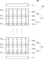
- FIG. 1 is a diagram conceptually illustrating an example of a filter having a liquid crystal polarization interference element of the present invention.
- 1 is a graph illustrating a filter having a liquid crystal polarization interference element of the present invention.
- 1 is a graph illustrating a filter having a liquid crystal polarization interference element of the present invention.
- FIG. 13 is a conceptual diagram showing a filter having a liquid crystal polarization interference element according to another example of the present invention.
- liquid crystal polarization interference element and filter of the present invention will be described in detail below based on the preferred embodiment shown in the attached drawings.
- a numerical range expressed using “to” means a range that includes the numerical values before and after “to” as the lower and upper limits.
- angles such as “45°”, “parallel”, “perpendicular” or “orthogonal” mean that the difference from the exact angle is within a range of less than 5 degrees.
- the difference from the exact angle is preferably less than 3 degrees, and more preferably less than 1 degree.
- terms such as “same” and “equal” include a generally accepted margin of error in the relevant technical field.
- Re( ⁇ ) represents the in-plane retardation at a wavelength ⁇ .
- Re( ⁇ ) is a value measured at a wavelength ⁇ using an AxoScan (manufactured by Axometrics).
- AxoScan manufactured by Axometrics.
- the liquid crystal polarization interference element of the present invention is The liquid crystal display device has two or more liquid crystal layer pairs each including a first liquid crystal layer and a second liquid crystal layer in a thickness direction;
- the first liquid crystal layer includes at least one first horizontally aligned liquid crystal layer formed by fixing a 1-1 liquid crystal compound having an optical axis aligned horizontally, and at least one first vertically aligned liquid crystal layer formed by fixing a 1-2 liquid crystal compound having an optical axis aligned vertically
- the second liquid crystal layer includes at least one second horizontally aligned liquid crystal layer formed by fixing a 2-1 liquid crystal compound having an optical axis aligned horizontally, and at least one second vertically aligned liquid crystal layer formed by fixing a 2-2 liquid crystal compound having an optical axis aligned vertically;
- the 1-1 liquid crystal compound and the 1-2 liquid crystal compound are both rod-shaped liquid crystal compounds or discotic liquid crystal compounds;
- the 2-1 liquid crystal compound and the 2-2 liquid crystal compound are both rod-shaped liquid crystal compounds or
- the filter of the present invention is The liquid crystal polarization interference element; Two polarizers sandwiching the liquid crystal polarization interference element in a thickness direction; The two polarizers are filters that are arranged with their transmission axes perpendicular to each other.
- FIG. 1 conceptually shows an example of the filter of the present invention having the liquid crystal polarization interference element of the present invention.
- 1 is a bandpass filter (narrow band filter) that transmits light in a specific wavelength range and blocks light of other wavelengths.
- the filter 10 has a first polarizer 12, a second polarizer 14, and a liquid crystal polarization interference element 16.
- the liquid crystal polarization interference element 16 is disposed between the first polarizer 12 and the second polarizer 14.
- the first polarizer 12 and the second polarizer 14 are polarizers (polarizing plates) that transmit linearly polarized light in a predetermined direction, and are arranged in a crossed Nicol state with their transmission axes perpendicular to each other.
- polarizers polarizing plates
- a liquid crystal polarization interference element 16 is disposed between the first polarizer 12 and the second polarizer 14 .
- the first polarizer 12 and the second polarizer 14 are spaced apart from the liquid crystal polarization interference element 16 .
- the present invention is not limited thereto, and the first polarizer 12 and the second polarizer 14 may be laminated in contact with the liquid crystal polarization interference element 16.
- the first polarizer 12 and the second polarizer 14 may be attached to each other with an adhesive that is transparent to transmitted light, such as OCA (Optical Clear Adhesive) and an acrylic adhesive, as necessary.
- OCA Optical Clear Adhesive
- the liquid crystal polarization interference element 16 is an optical element that acts as a ⁇ /2 retardation plate for light in a specific wavelength range (specific wavelength) and does not act as a retardation layer for other light.
- the first polarizer 12 and the second polarizer 14 are polarizers arranged in a crossed Nicol state with their transmission axes perpendicular to each other. Therefore, of the light incident on the filter 10, only linearly polarized light in a predetermined direction is transmitted through the first polarizer 12. Of this linearly polarized light, light of a specific wavelength has its polarization direction rotated by 90° by the liquid crystal polarization interference element 16, and is incident on and transmitted through the second polarizer 14 arranged in a crossed Nicol configuration with the first polarizer 12.
- the filter 10 functions as a bandpass filter that transmits only light in a specific wavelength range and blocks other light.
- the liquid crystal polarization interference element 16 is formed by laminating an even number of liquid crystal layers, each of which is made by fixing liquid crystal compounds oriented in a predetermined direction. Specifically, the liquid crystal polarization interference element 16 is formed by laminating two or more liquid crystal layer sets 26, each of which is made up of a first liquid crystal layer 20 and a second liquid crystal layer 24, in the thickness direction. Therefore, the total number of layers of the first liquid crystal layer 20 and the second liquid crystal layer 24 is an even number. In the example shown in FIG. 1, the liquid crystal polarization interference element 16 has first to n-th liquid crystal layer sets.
- the first liquid crystal layer 20 and the second liquid crystal layer 24 each include at least one horizontally aligned liquid crystal layer formed by fixing liquid crystal compounds whose optical axes are aligned horizontally, and at least one vertically aligned liquid crystal layer formed by fixing liquid crystal compounds whose optical axes are aligned vertically.
- liquid crystal layer set 26 the liquid crystal layer set closest to the first polarizer 12
- the liquid crystal layer set closest to the second polarizer 14 is referred to as the nth liquid crystal layer set 26n, and when there is no need to distinguish between the liquid crystal layer sets, they are also referred to as liquid crystal layer set 26.
- the first liquid crystal layer included in the first liquid crystal layer set 26a is represented by the reference symbol 20a
- the second liquid crystal layer is represented by the reference symbol 24a
- the first liquid crystal layer included in the nth liquid crystal layer set 26n is represented by the reference symbol 20n
- the second liquid crystal layer is represented by the reference symbol 24n
- the horizontally aligned liquid crystal layer included in the first liquid crystal layer 20a of the first liquid crystal layer set 26a is referred to as the first horizontally aligned liquid crystal layer 20Ha
- the horizontally aligned liquid crystal layer included in the first liquid crystal layer 20n of the n-th liquid crystal layer set 26n is referred to as the first horizontally aligned liquid crystal layer 20Hn
- the first horizontally aligned liquid crystal layer 20Hn when it is not necessary to distinguish between the first horizontally aligned liquid crystal layers, they are also referred to as the first horizontally aligned liquid crystal layer 20H.
- the vertically aligned liquid crystal layer included in the first liquid crystal layer 20a of the first liquid crystal layer set 26a is referred to as the first vertically aligned liquid crystal layer 20Va
- the vertically aligned liquid crystal layer included in the first liquid crystal layer 20n of the n-th liquid crystal layer set 26n is referred to as the first vertically aligned liquid crystal layer 20Vn
- the first vertically aligned liquid crystal layer 20Vn when it is not necessary to distinguish between the first vertically aligned liquid crystal layers, they are also referred to as the first vertically aligned liquid crystal layer 20V.
- the horizontally aligned liquid crystal layer included in the second liquid crystal layer 24a of the first liquid crystal layer group 26a is referred to as the second horizontally aligned liquid crystal layer 24Ha
- the horizontally aligned liquid crystal layer included in the second liquid crystal layer 24n of the n-th liquid crystal layer group 26n is referred to as the second horizontally aligned liquid crystal layer 24Hn
- the second horizontally aligned liquid crystal layer 24Hn when it is not necessary to distinguish between the second horizontally aligned liquid crystal layers, they are also referred to as the second horizontally aligned liquid crystal layer 24H.
- the vertically aligned liquid crystal layer included in the second liquid crystal layer 24a of the first liquid crystal layer group 26a is referred to as the second vertically aligned liquid crystal layer 24Va
- the vertically aligned liquid crystal layer included in the second liquid crystal layer 24n of the n-th liquid crystal layer group 26n is referred to as the second vertically aligned liquid crystal layer 24Vn
- the second vertically aligned liquid crystal layer 20V when it is not necessary to distinguish between the second vertically aligned liquid crystal layers, they are also referred to as the second vertically aligned liquid crystal layer 20V.
- first liquid crystal layer 20a and the second liquid crystal layer 24a of the first liquid crystal layer group 26a as representatives, but basically the first liquid crystal layer 20 and the second liquid crystal layer 24 of each liquid crystal layer group 26 have the same configuration.
- the first horizontally aligned liquid crystal layer 20Ha of the first liquid crystal layer 20a is a liquid crystal layer in which the 1-1 rod-shaped liquid crystal compound 18 h1a is horizontally aligned and fixed with its optical axis.
- the optical axis of the rod-shaped liquid crystal compound is the long axis direction. That is, the first horizontally aligned liquid crystal layer 20Ha is a layer in which the 1-1 rod-shaped liquid crystal compound 18 h1a is aligned so that its long axis direction is parallel to the main surface of the first horizontally aligned liquid crystal layer 20Ha. Also, as shown in FIG.
- each of the 1-1 rod-shaped liquid crystal compounds 18 h1a is aligned so that its optical axis is aligned in a predetermined direction. That is, the first horizontally aligned liquid crystal layer 20Ha is a so-called (positive) A plate.
- the main surface means the largest surface of the sheet-like material (each layer).
- the first vertically aligned liquid crystal layer 20Va of the first liquid crystal layer 20a is a liquid crystal layer in which the first-2 rod-shaped liquid crystal compound 18 v1a is fixed with its optical axis vertically aligned. That is, the first vertically aligned liquid crystal layer 20Va is a layer in which the first-2 rod-shaped liquid crystal compound 18 v1a is aligned so that its long axis direction is perpendicular to the main surface of the first vertically aligned liquid crystal layer 20Va. That is, the first vertically aligned liquid crystal layer 20Va is a so-called (positive) C plate.
- the second horizontally aligned liquid crystal layer 24Ha of the second liquid crystal layer 24a is a liquid crystal layer in which the 2-1 rod-shaped liquid crystal compound 18 h2a is fixed with its optical axis aligned horizontally. That is, the second horizontally aligned liquid crystal layer 24Ha is a layer in which the 2-1 rod-shaped liquid crystal compound 18 h2a is aligned so that its long axis direction is parallel to the main surface of the second horizontally aligned liquid crystal layer 24Ha. Also, as shown in FIG.
- each of the 2-1 rod-shaped liquid crystal compounds 18 h2a is aligned so that its optical axis is aligned in a predetermined direction. That is, the second horizontally aligned liquid crystal layer 24Ha is a so-called (positive) A plate.
- rod-shaped liquid crystal compounds 18 h2a when it is not necessary to distinguish between the rod-shaped liquid crystal compounds constituting each liquid crystal layer, they are also referred to as rod-shaped liquid crystal compounds 18.
- the second vertically aligned liquid crystal layer 24Va of the second liquid crystal layer 24a is a liquid crystal layer in which the second-2 rod-shaped liquid crystal compound 18 v2a is fixed with its optical axis vertically aligned. That is, the second vertically aligned liquid crystal layer 24Va is a layer in which the second-2 rod-shaped liquid crystal compound 18 v2a is aligned so that its long axis direction is perpendicular to the main surface of the second vertically aligned liquid crystal layer 24Va. That is, the second vertically aligned liquid crystal layer 24Va is a so-called (positive) C plate.
- the absolute value of the sum of the in-plane retardation of the second horizontally aligned liquid crystal layer 24Ha is about twice the absolute value of the sum of the thickness direction retardation of the second vertically aligned liquid crystal layer 24Va. This point will be discussed in more detail later.
- the in-plane slow axis of the first liquid crystal layer 20a and the in-plane slow axis of the second liquid crystal layer 24a intersect with each other.
- the direction of the in-plane slow axis of the first liquid crystal layer 20a is mainly due to the alignment direction of the 1-1 rod-shaped liquid crystal compound 18 h1a in the first horizontally aligned liquid crystal layer 20Ha.
- the direction of the in-plane slow axis of the second liquid crystal layer 24a is mainly due to the alignment direction of the 2-1 rod-shaped liquid crystal compound 18 h2a in the second horizontally aligned liquid crystal layer 24Ha.
- the first liquid crystal layer 20a and the second liquid crystal layer 24a are laminated such that the alignment direction (long axis direction) of the 1-1 rod-shaped liquid crystal compound 18 h1a in the first horizontally aligned liquid crystal layer 20Ha intersects with the alignment direction (long axis direction) of the 2-1 rod-shaped liquid crystal compound 18 h2a in the second horizontally aligned liquid crystal layer 24Ha.
- the in-plane retardation of the first liquid crystal layer 20a and the in-plane retardation of the second liquid crystal layer 24a are approximately equal.
- Such a first liquid crystal layer set 26a is arranged so that the bisector of the angle between the direction of the slow axis of the first liquid crystal layer 20a and the direction of the slow axis of the second liquid crystal layer 24a is parallel to one of the transmission axes or absorption axes of the polarizers (first polarizer 12 and second polarizer 14) arranged in crossed Nicols.
- first polarizer 12 and second polarizer 14 are taken as a reference line and, for example, the clockwise angle as viewed from the first polarizer 12 side is taken as positive and the counterclockwise angle is taken as negative, the angle of the slow axis of the first liquid crystal layer 20a and the angle of the slow axis of the second liquid crystal layer 24a from the reference line will be the same in absolute value, although the positive and negative angles will be different.
- the liquid crystal polarization interference element 16 of the present invention has two or more such liquid crystal layer sets 26.
- the multiple liquid crystal layer sets 26 are arranged so that the bisectors of the angle between the direction of the slow axis of the first liquid crystal layer 20 and the direction of the slow axis of the second liquid crystal layer 24 are parallel to each other.
- all of the first liquid crystal layers 20 have the same configuration, and all of the second liquid crystal layers 24 also have the same configuration. That is, in the liquid crystal polarization interference element 16 shown in FIG. 1, all of the first liquid crystal layers 20 have the same in-plane retardation ( ⁇ nd) and in-plane slow axis angle, and all of the second liquid crystal layers 24 have the same in-plane retardation ( ⁇ nd) and in-plane slow axis angle.
- Light passing through such a liquid crystal polarization interference element 16 is repeatedly and alternately influenced by the slow axis of the first liquid crystal layer 20 at a certain angle and the slow axis of the second liquid crystal layer 24 at an angle that has the same absolute value as the angle but a different sign.
- liquid crystal polarization interference element 16 by setting ⁇ nd of the first liquid crystal layer 20 and the second liquid crystal layer 24 according to the wavelength range transmitted through the filter 10, and further adjusting the angle of the slow axis in the first liquid crystal layer 20 and the second liquid crystal layer 24 according to the total number of layers of the first liquid crystal layer 20 and the second liquid crystal layer 24, it is possible to form a liquid crystal polarization interference element 16 that acts as a ⁇ /2 retardation plate for light in a specific wavelength range and does not act as a retardation plate for other light, i.e., does not sense retardation.
- the filter 10 in which the liquid crystal polarization interference element 16, which acts as a ⁇ /2 retardation plate only for light in a specific wavelength range, is arranged between the first polarizer 12 and the second polarizer 14 arranged in crossed Nicols, rotates the polarization direction of the specific wavelength light among the linearly polarized light transmitted through the first polarizer 12 by 90° by the liquid crystal polarization interference element 16 and transmits it through the second polarizer 14 arranged in crossed Nicols with the first polarizer 12, as described above.
- the liquid crystal polarization interference element 16 does not act as a retardation layer for light outside the specific wavelength range, the linearly polarized light transmitted through the first polarizer 12 passes through the liquid crystal polarization interference element 16 and is blocked by the second polarizer 14. Through this optical action, the filter 10 becomes a bandpass filter that transmits only light in a specific wavelength range and blocks other light.
- the liquid crystal polarization interference element 16 acts as a ⁇ /2 retardation plate only for light in a specific wavelength range. Accordingly, the in-plane retardation ( ⁇ nd) of the first liquid crystal layer 20 and the second liquid crystal layer 24 is set to a wavelength at which the liquid crystal polarization interference element 16 is expected to act as a ⁇ /2 retardation plate, i.e., half the central wavelength (half wavelength) of the wavelength range expected to pass through the filter 10.
- the ⁇ nd of the first liquid crystal layer 20 and the second liquid crystal layer 24 may be set to 275 nm.
- the first liquid crystal layer 20 is composed of the first horizontally aligned liquid crystal layer 20H and the first vertically aligned liquid crystal layer 20V, the in-plane retardation of the first liquid crystal layer 20 is mainly caused by the first horizontally aligned liquid crystal layer 20H, so the ⁇ nd of the first horizontally aligned liquid crystal layer 20H may be set to 275 nm.
- the in-plane retardation of the second liquid crystal layer 24 is mainly caused by the second horizontally aligned liquid crystal layer 24H, so the ⁇ nd of the second horizontally aligned liquid crystal layer 24H may be set to 275 nm.
- the ⁇ nd of the first liquid crystal layer 20 and the second liquid crystal layer 24 may have an error of about ⁇ 10% with respect to half the central wavelength of the wavelength range transmitted by the filter 10 .
- the absolute value of the sum of the in-plane retardation of the first horizontally aligned liquid crystal layer 20H of the first liquid crystal layer 20 is about 1.33 to 4 times, and preferably about twice, the absolute value of the sum of the thickness direction retardation of the first vertically aligned liquid crystal layer 20V.
- the absolute value of the sum of the in-plane retardation of the second horizontally aligned liquid crystal layer 24H of the second liquid crystal layer 24 is about 1.33 to 4 times, and preferably about twice, the absolute value of the sum of the thickness direction retardation of the second vertically aligned liquid crystal layer 24V.
- the first liquid crystal layer 20 and the second liquid crystal layer 24 each have a horizontally aligned liquid crystal layer (20H, 24H) and a vertically aligned liquid crystal layer (20V, 24V), and the absolute value of the sum of the in-plane retardation of the horizontally aligned liquid crystal layer is about 1.33 to 4 times, and preferably about 2 times, the absolute value of the sum of the thickness direction retardation of the vertically aligned liquid crystal layer.
- the in-plane retardation of the horizontally aligned liquid crystal layer (20H, 24H) can be measured using an Axo Scan (0PMF-1, manufactured by Axometrics).
- the thickness retardation of the vertically aligned liquid crystal layer (20V, 24V) can be measured using an Axo Scan (0PMF-1, manufactured by Axometrics).
- the in-plane retardation and thickness retardation can be measured by separating them through optical analysis even when the in-plane periodic structure layer and the thickness periodic structure layer are stacked.
- the number of liquid crystal layer pairs 26 that the liquid crystal polarization interference element 16 has can be detected by cutting the liquid crystal polarization interference element 16 at an angle and analyzing the orientation direction of the liquid crystal on the surface of the cross section. This method is described in detail in "Depth-Dependent Determination of Molecular Orientation for WV-Film" by Yohei Takahashi et al. (FMC8-3, IDW '04, pp. 651-654).
- the horizontally aligned liquid crystal layer and the vertically aligned liquid crystal layer of each of the first liquid crystal layer 20 and the second liquid crystal layer 24 in each liquid crystal layer set can be identified by cutting the liquid crystal polarization interference element 16 obliquely and analyzing the alignment direction of the liquid crystal compound on the surface of the cross section. This method is described in detail in the above-mentioned paper by Yohei Takahashi et al.
- the direction of the in-plane slow axis of the first liquid crystal layer 20, i.e., the first horizontally aligned liquid crystal layer, and the direction of the in-plane slow axis of the second liquid crystal layer 24, i.e., the second horizontally aligned liquid crystal layer, in each liquid crystal layer set can be detected by cutting the liquid crystal polarization interference element 16 obliquely and analyzing the orientation direction of the liquid crystal compound on the surface of the cross section.
- the in-plane retardation of each of the first liquid crystal layer 20 and the second liquid crystal layer 24 can be measured using an AxoScan manufactured by Axometrics, Inc., or the like.
- ⁇ n is the birefringence of the rod-shaped liquid crystal compound 18 that constitutes the first liquid crystal layer 20 and the second liquid crystal layer 24.
- d is the thickness of the first liquid crystal layer 20 and the second liquid crystal layer 24. Therefore, the in-plane retardation may be obtained by measuring the birefringence ⁇ n and thickness d of the rod-shaped liquid crystal compound 18.
- the birefringence ⁇ n of the liquid crystal compound may also be measured using an AxoScan manufactured by Axometrics, Inc., or the like.
- the angle of the slow axis (angle with respect to the transmission axis or absorption axis of a reference polarizer) in the first liquid crystal layer 20 and the second liquid crystal layer 24 constituting the liquid crystal polarization interference element 16 can be set by simulation to an optimal angle at which the liquid crystal polarization interference element 16 acts as a ⁇ /2 phase difference plate, depending on the central wavelength of the wavelength range expected to pass through the filter 10 and the total number N of layers of the first liquid crystal layer 20 and the second liquid crystal layer 24.
- a general optical simulation means can be used, and it is also possible to perform the calculations using LCD Master 1D (manufactured by Shintech Co., Ltd., Ver. 9.8.0.0).
- each of the first liquid crystal layer 20 and the second liquid crystal layer 24 there is no restriction on the thickness d of each of the first liquid crystal layer 20 and the second liquid crystal layer 24, and the thickness can be appropriately set so that the in-plane retardation ( ⁇ nd) of each of the first liquid crystal layer 20 and the second liquid crystal layer 24 is half the central wavelength of the wavelength range transmitted by the filter 10, depending on the liquid crystal compound used.
- the thickness d of each of the first liquid crystal layer 20 and the second liquid crystal layer 24 is preferably 1 to 5 ⁇ m, and more preferably 1 to 3 ⁇ m.
- each of the first horizontally aligned liquid crystal layer 20H and the first vertically aligned liquid crystal layer 20V in the first liquid crystal layer 20 and the thickness of each of the second horizontally aligned liquid crystal layer 24H and the second vertically aligned liquid crystal layer 24V in the second liquid crystal layer 24.
- the thickness may be appropriately set so that the absolute value of the sum of the in-plane retardation of the horizontally aligned liquid crystal layers (20H, 24H) is approximately twice the absolute value of the sum of the thickness direction retardation of the vertically aligned liquid crystal layers (20V, 24V) depending on the liquid crystal compound used, etc.
- the thickness of the first horizontally aligned liquid crystal layer 20H may be approximately twice the thickness of the first vertically aligned liquid crystal layer 20V in order to make the absolute value of the sum of the in-plane retardation of the first horizontally aligned liquid crystal layer 20H approximately twice the absolute value of the sum of the thickness direction retardation of the first vertically aligned liquid crystal layer 20V.
- the thickness of the second horizontally aligned liquid crystal layer 24H may be approximately twice the thickness of the second vertically aligned liquid crystal layer 24V in order to make the absolute value of the sum of the in-plane retardation of the second horizontally aligned liquid crystal layer 24H approximately twice the absolute value of the sum of the thickness direction retardation of the second vertically aligned liquid crystal layer 24V.
- the first horizontally aligned liquid crystal layer 20H in the first liquid crystal layer 20 and the second horizontally aligned liquid crystal layer 24H in the second liquid crystal layer 20 are formed using the same type of liquid crystal compound, that is, when the 1-1 rod-shaped liquid crystal compound 18 h1a and the 2-1 rod-shaped liquid crystal compound 18 h2a are of the same type, in order to make the in-plane retardation of the first liquid crystal layer 20 and the in-plane retardation of the second liquid crystal layer 24 approximately equal, the thickness of the first horizontally aligned liquid crystal layer 20H and the thickness of the horizontally aligned liquid crystal layer 24H may be made approximately equal.
- the first liquid crystal layer 20 has one each of the first horizontally aligned liquid crystal layer 20H and the first vertically aligned liquid crystal layer 20V, but this is not limited to this.
- the first liquid crystal layer 20 may have multiple layers of the first horizontally aligned liquid crystal layer 20H and/or the first vertically aligned liquid crystal layer 20V.
- the sum of the in-plane retardation of the multiple first horizontally aligned liquid crystal layers 20H may be approximately twice the sum of the thickness retardation of the multiple first vertically aligned liquid crystal layers 20V.
- one second liquid crystal layer 24 has one each of the second horizontally aligned liquid crystal layer 24H and the second vertically aligned liquid crystal layer 24V, but this is not limited to this.
- the second liquid crystal layer 24 may have multiple layers of the second horizontally aligned liquid crystal layer 24H and/or the second vertically aligned liquid crystal layer 24V.
- the sum of the in-plane retardation of the multiple second horizontally aligned liquid crystal layers 24H may be approximately twice the sum of the thickness retardation of the multiple second vertically aligned liquid crystal layers 24V.
- the liquid crystal layer set 26 is two or more, that is, four or more layers, and is an even number.
- the total number of layers of the first liquid crystal layer 20 and the second liquid crystal layer 24 is preferably 6 to 30 layers, more preferably 6 to 20 layers, and even more preferably 6 to 10 layers. That is, the number of liquid crystal layer pairs 26 is preferably 3 to 15 pairs, more preferably 3 to 10 pairs, and even more preferably 3 to 5 pairs.
- the total number of layers of the first liquid crystal layer 20 and the second liquid crystal layer 24, i.e., the number of liquid crystal layer sets 26, can be selected appropriately depending on the width of the transmission wavelength range required for the filter 10, with a smaller number of layers being selected when a broad band is preferred and a larger number of layers being selected when a narrow band is required.
- all of the liquid crystal layer pairs have the same configuration. That is, in the liquid crystal polarization interference element 16 shown in FIG. 1, all of the first liquid crystal layers 20 have the same configuration, and all of the second liquid crystal layers 24 also have the same configuration. That is, in the liquid crystal polarization interference element 16 shown in FIG. 1, all of the first liquid crystal layers 20 have the same in-plane retardation ( ⁇ nd) and in-plane slow axis angle, and all of the second liquid crystal layers 24 have the same in-plane retardation ( ⁇ nd) and in-plane slow axis angle.
- the present invention is not limited to this, and the liquid crystal layer may have a distribution of the in-plane retardation ( ⁇ nd) and the angle of the in-plane slow axis in the thickness direction. That is, in the present invention, as long as the in-plane retardation ( ⁇ nd) of the first liquid crystal layer and the second liquid crystal layer in each liquid crystal layer pair are equal, and the absolute values of the angles of the in-plane slow axes are equal, the in-plane retardation ( ⁇ nd) and/or the angle of the in-plane slow axis of the first liquid crystal layer and the second liquid crystal layer may differ for each liquid crystal layer pair.
- the liquid crystal layer pair in the middle of the thickness direction (stacking direction) and the liquid crystal layer pairs on both sides of the thickness direction have different in-plane retardation ( ⁇ nd) of the first liquid crystal layer and the second liquid crystal layer, and the angle of the in-plane slow axis, i.e., the angle between the in-plane slow axis of the first liquid crystal layer and the in-plane slow axis of the second liquid crystal layer, are different.
- the in-plane retardation ( ⁇ nd) of the liquid crystal layers (first and second liquid crystal layers) of the liquid crystal layer pairs on both sides in the thickness direction may be made larger than that of the liquid crystal layers (first and second liquid crystal layers) of the liquid crystal layer pair in the center in the thickness direction, and the absolute value of the angle of the in-plane slow axis may be made smaller.
- the liquid crystal polarization interference element has eight liquid crystal layers, i.e., four liquid crystal layer sets
- the first liquid crystal layer (first layer) has an in-plane retardation of ⁇ nd1 and an in-plane slow axis angle of ⁇ 1
- the second liquid crystal layer (second layer) has an in-plane retardation of ⁇ nd1 and an in-plane slow axis angle of ⁇ 1
- the first liquid crystal layer (third layer) has an in-plane retardation of ⁇ nd2 smaller than ⁇ nd1, an in-plane slow axis angle of ⁇ 2 larger than ⁇ 1
- the second liquid crystal layer (fourth layer) has an in-plane retardation of ⁇ nd2, and an in-plane slow axis angle of ⁇ 2
- the first liquid crystal layer (fifth layer) has an in-plane retardation of ⁇ nd2 and an in-plane slow axis angle of ⁇ 2
- a bandpass filter generates transmission wavelength ranges called side lobes, as indicated by arrows S in the figure, at wavelengths shorter and longer than the target transmission wavelength range, on either side of the target transmission wavelength range.
- this side lobe can be reduced by increasing the in-plane retardation of the liquid crystal layers of the liquid crystal layer pairs on both sides of the thickness direction and decreasing the angle of the in-plane slow axis compared to the liquid crystal layer of the liquid crystal layer pair at the center of the thickness direction.
- the in-plane retardation of the liquid crystal layer can be adjusted, for example, by changing the thickness of the liquid crystal layer, but it can also be adjusted by changing the liquid crystal compound used.
- the in-plane retardation and the in-plane slow axis angle of the liquid crystal layer of the liquid crystal layer pairs on both sides in the thickness direction can be set by simulation to the optimal in-plane retardation and in-plane slow axis angle that allows the liquid crystal polarization interference element to act as a ⁇ /2 phase difference plate and reduce side lobes.
- the liquid crystal compound constituting the first horizontally aligned liquid crystal layer 20H of the first liquid crystal layer 20 and the liquid crystal compound constituting the first vertically aligned liquid crystal layer 20V are both rod-shaped liquid crystal compounds
- the liquid crystal compound constituting the second horizontally aligned liquid crystal layer 24H of the second liquid crystal layer 24 and the liquid crystal compound constituting the second vertically aligned liquid crystal layer 24V are both rod-shaped liquid crystal compounds, but the present invention is not limited to this.
- the liquid crystal compound constituting the first horizontally aligned liquid crystal layer 21H of the first liquid crystal layer 21 and the liquid crystal compound constituting the first vertically aligned liquid crystal layer 21V may both be discotic liquid crystal compounds 19
- the liquid crystal compound constituting the second horizontally aligned liquid crystal layer 25H of the second liquid crystal layer 25 and the liquid crystal compound constituting the second vertically aligned liquid crystal layer 25V may both be discotic liquid crystal compounds 19.
- the direction of the optical axis of the discotic liquid crystal compound is perpendicular to the disc surface. Therefore, as shown in FIG. 4, for example, the 1-1 discotic liquid crystal compound 19 h1a constituting the first horizontally aligned liquid crystal layer 21Ha of the first liquid crystal layer 21a of the first liquid crystal layer set 27a is aligned so that the optical axis is parallel to the main surface of the first horizontally aligned liquid crystal layer 21Ha, and therefore the disc surface is aligned perpendicular to the main surface. Also, as shown in FIG. 4, in the first horizontally aligned liquid crystal layer 21Ha, each of the 1-1 discotic liquid crystal compounds 19 h1a is aligned so that its optical axis is aligned in a predetermined direction. That is, the first horizontally aligned liquid crystal layer 21Ha is a so-called (negative) A plate.
- the first-2 discotic liquid crystal compound 19 v1a constituting the first vertically aligned liquid crystal layer 21Va of the first liquid crystal layer 21a is aligned so that its optical axis is perpendicular to the main surface of the first vertically aligned liquid crystal layer 21Va, and therefore its disc surface is aligned parallel to the main surface.
- the first vertically aligned liquid crystal layer 21Va is a so-called (negative) C plate.
- the absolute value of the sum of the in-plane retardation of the first horizontally aligned liquid crystal layer 21Ha is 1.33 to 4 times, and preferably about twice, the absolute value of the sum of the thickness direction retardation of the first vertically aligned liquid crystal layer 21Va.
- the 2-1 discotic liquid crystal compound 19 h2a constituting the first horizontally aligned liquid crystal layer 25Ha of the second liquid crystal layer 25a of the first liquid crystal layer set 27a is aligned so that its optical axis is parallel to the main surface of the second horizontally aligned liquid crystal layer 25Ha, and therefore the disc surface is aligned perpendicular to the main surface.
- each of the 2-1 discotic liquid crystal compounds 19 h2a is aligned so that its optical axis is aligned in a predetermined direction. That is, the second horizontally aligned liquid crystal layer 25Ha is a so-called (negative) A plate.
- the second-2 discotic liquid crystal compound 19 v2a constituting the second vertically aligned liquid crystal layer 25Va of the second liquid crystal layer 25a is aligned so that its optical axis is perpendicular to the principal surface of the second vertically aligned liquid crystal layer 25Va, and therefore its disc surface is aligned parallel to the principal surface.
- the second vertically aligned liquid crystal layer 25Va is a so-called (negative) C plate.
- the absolute value of the sum of the in-plane retardation of the second horizontally aligned liquid crystal layer 25Ha is 1.33 to 4 times, and preferably about twice, the absolute value of the sum of the thickness direction retardation of the second vertically aligned liquid crystal layer 25Va.
- the in-plane slow axis of the first liquid crystal layer 21a and the in-plane slow axis of the second liquid crystal layer 25a intersect with each other.
- the direction of the in-plane slow axis of the first liquid crystal layer 21a is mainly due to the alignment direction of the 1-1 discotic liquid crystal compound 19 h1a in the first horizontally aligned liquid crystal layer 21Ha.
- the direction of the in-plane slow axis of the second liquid crystal layer 25a is mainly due to the alignment direction of the 2-1 discotic liquid crystal compound 19 h2a in the second horizontally aligned liquid crystal layer 25Ha.
- the first liquid crystal layer 21a and the second liquid crystal layer 25a are laminated such that the alignment direction (optical axis) of the 1-1 discotic liquid crystal compound 19 h1a in the first horizontally aligned liquid crystal layer 21Ha intersects with the alignment direction (optical axis) of the 2-1 discotic liquid crystal compound 19 h2a in the second horizontally aligned liquid crystal layer 25Ha.
- the in-plane retardation of the first liquid crystal layer 21a and the in-plane retardation of the second liquid crystal layer 25a are approximately equal.
- the liquid crystal polarization interference element 16b has two or more such liquid crystal layer sets 27.
- the multiple liquid crystal layer sets 27 are arranged so that the bisectors of the angle between the direction of the slow axis of the first liquid crystal layer 21 and the direction of the slow axis of the second liquid crystal layer 25 are parallel to each other.
- the liquid crystal polarization interference element 16b acts as a ⁇ /2 retardation plate only for light in a specific wavelength range, so the filter 10 in which this liquid crystal polarization interference element 16b is placed between the first polarizer 12 and the second polarizer 14 becomes a bandpass filter that transmits only light in a specific wavelength range and blocks other light.
- the first liquid crystal layer 21 and the second liquid crystal layer 25 each have a horizontally aligned liquid crystal layer (21H, 25H) and a vertically aligned liquid crystal layer (21V, 25V), and the absolute value of the sum of the in-plane retardation of the horizontally aligned liquid crystal layer is 1.33 to 4 times, and preferably about twice, the absolute value of the sum of the thickness direction retardation of the vertically aligned liquid crystal layer.
- all the liquid crystal layers are made of rod-shaped liquid crystal compounds, and in the example shown in FIG. 4, all the liquid crystal layers are made of discotic liquid crystal compounds, but this is not limiting.
- the liquid crystal compounds constituting the first horizontally aligned liquid crystal layer 20H and the first vertically aligned liquid crystal layer 20V of the first liquid crystal layer 20 may all be rod-shaped liquid crystal compounds
- the liquid crystal compounds constituting the second horizontally aligned liquid crystal layer 25H and the second vertically aligned liquid crystal layer 25V of the second liquid crystal layer 25 may all be discotic liquid crystal compounds.
- the liquid crystal compounds constituting the first horizontally aligned liquid crystal layer 21H and the first vertically aligned liquid crystal layer 21V of the first liquid crystal layer 21 may all be discotic liquid crystal compounds, and the liquid crystal compounds constituting the second horizontally aligned liquid crystal layer 24H and the second vertically aligned liquid crystal layer 24V of the second liquid crystal layer 24 may all be rod-shaped liquid crystal compounds.
- liquid crystal compounds constituting the first horizontally aligned liquid crystal layer and the first vertically aligned liquid crystal layer of the first liquid crystal layer of all liquid crystal layer pairs are not limited to being rod-shaped liquid crystal compounds or discotic liquid crystal compounds, and the first horizontally aligned liquid crystal layer and the first vertically aligned liquid crystal layer of the first liquid crystal layer of one liquid crystal layer pair may be formed using rod-shaped liquid crystal compounds, and the first horizontally aligned liquid crystal layer and the first vertically aligned liquid crystal layer of the first liquid crystal layer of another liquid crystal layer pair may be formed using discotic liquid crystal compounds.
- the liquid crystal compounds constituting the second horizontally aligned liquid crystal layer and the second vertically aligned liquid crystal layer of the second liquid crystal layer of all liquid crystal layer pairs are not limited to being rod-shaped liquid crystal compounds or discotic liquid crystal compounds, and the second horizontally aligned liquid crystal layer and the second vertically aligned liquid crystal layer of the second liquid crystal layer of one liquid crystal layer pair may be formed using rod-shaped liquid crystal compounds, and the second horizontally aligned liquid crystal layer and the second vertically aligned liquid crystal layer of the second liquid crystal layer of another liquid crystal layer pair may be formed using discotic liquid crystal compounds.
- both the first and second liquid crystal layers are configured to have a vertically aligned liquid crystal layer and a horizontally aligned liquid crystal layer stacked in this order from the first polarizer 12 side, but this is not limited to this, and the layers may also be configured to have a horizontally aligned liquid crystal layer and a vertically aligned liquid crystal layer stacked in this order from the first polarizer 12 side.
- the first and second liquid crystal layers may be formed by a coating method and directly laminated, or the first and second liquid crystal layers may be prepared in the form of sheets, which are alternately laminated and bonded with an optical bonding layer that is transparent to transmitted light, such as OCA (Optical Clear Adhesive), an acrylic adhesive, an adhesive, or a polymer layer.
- OCA Optical Clear Adhesive
- the refractive index of the optical bonding layer is close to that of the liquid crystal layer. Specifically, it is preferable that the difference in refractive index is 0.3 or less.
- the refractive index of the optical bonding layer is a value between the two birefringences of the liquid crystal layer, since the difference in refractive index from either of the two refractive indexes is small.
- direct lamination by a coating method without an adhesive layer is preferable.
- Such a liquid crystal polarization interference element may be prepared by a known method.
- the first and second liquid crystal layers are produced by a coating method using a liquid crystal composition.
- the first and second liquid crystal layers can be formed by forming a horizontally aligned liquid crystal layer and a vertically aligned liquid crystal layer, respectively, and then laminating them and adhering them with an adhesive that is transparent to transmitted light, such as OCA (Optical Clear Adhesive) or an acrylic pressure sensitive adhesive.
- OCA Optical Clear Adhesive
- a horizontally aligned liquid crystal layer can be formed and then a vertically aligned liquid crystal layer can be formed on the horizontally aligned liquid crystal layer, or a vertically aligned liquid crystal layer can be formed and then a horizontally aligned liquid crystal layer can be formed on the vertically aligned liquid crystal layer.
- the horizontally aligned liquid crystal layer can be produced by a conventional method for forming a horizontally aligned liquid crystal layer.
- an alignment film that is oriented in one direction is formed on an appropriately selected support.
- the alignment film may be any of known alignment films, such as a rubbed film made of an organic compound such as a polymer, an obliquely evaporated film of an inorganic compound, a film having microgrooves, a film in which LB (Langmuir-Blodgett) films of organic compounds such as ⁇ -tricosanoic acid, dioctadecylmethylammonium chloride, and methyl stearate are accumulated by the Langmuir-Blodgett method, and a film in which an alignment film-forming coating liquid containing a photoalignment material is applied to the surface of a support, dried, and the coating film is exposed to light using a polarizer such as a wire grid polarizer.
- a polarizer such as a wire grid polarizer
- a composition (liquid crystal composition) containing a liquid crystal compound is prepared for forming a horizontally aligned liquid crystal layer.
- the solvent for preparing the composition is not limited and can be selected appropriately depending on the purpose, but organic solvents are preferred.
- organic solvents are preferred.
- the organic solvent can be selected appropriately depending on the purpose, and examples include ketones, alkyl halides, amides, sulfoxides, heterocyclic compounds, hydrocarbons, esters, and ethers. These may be used alone or in combination of two or more. Among these, ketones are preferred when the burden on the environment is taken into consideration.
- a composition for forming a horizontally aligned liquid crystal layer is applied to the surface of the alignment film to align the liquid crystal compound, and then the composition is dried and, if necessary, cured by exposure to ultraviolet light, etc., to form a horizontally aligned liquid crystal layer.
- the vertically aligned liquid crystal layer can be produced by a conventional method for forming a vertically aligned liquid crystal layer.
- the horizontally aligned liquid crystal layer and the vertically aligned liquid crystal layer prepared as described above can be attached with OCA or the like to produce the first and second liquid crystal layers, respectively.
- the first and second liquid crystal layers thus prepared are bonded with OCA or the like so that the angle of the in-plane slow axis is a specified angle to form a liquid crystal layer set.
- a number of such liquid crystal layer sets are prepared, and the liquid crystal layer sets are then stacked to produce a liquid crystal polarization interference element.
- the liquid crystal layer sets can also be laminated together by bonding with OCA or the like. When stacking the liquid crystal layer sets together, they are stacked so that the bisectors of the angle between the in-plane slow axis of the first liquid crystal layer and the in-plane slow axis of the second liquid crystal layer of each liquid crystal layer set are parallel.
- the liquid crystal polarization interference element thus produced can be arranged, for example, so that the transmission axis of the first polarizer is parallel to the bisector of the angle between the in-plane slow axis of the first liquid crystal layer and the in-plane slow axis of the second liquid crystal layer of each liquid crystal layer pair, and further, by arranging the second polarizer and the first polarizer in a crossed Nicol state, a filter such as that shown in Figure 1 or Figure 4 can be produced.
- the rod-like liquid crystal compound 18 is not limited, and various known liquid crystal compounds can be used.
- the rod-shaped liquid crystal compound azomethines, azoxys, cyanobiphenyls, cyanophenyl esters, benzoates, cyclohexane carboxylic acid phenyl esters, cyanophenylcyclohexanes, cyano-substituted phenylpyrimidines, alkoxy-substituted phenylpyrimidines, phenyldioxanes, tolanes, and alkenylcyclohexylbenzonitriles are preferably used. Not only the above-mentioned low molecular weight liquid crystal molecules, but also polymeric liquid crystal molecules can be used.
- rod-shaped liquid crystal compounds examples include Makromol. Chem. , Vol. 190, p. 2255 (1989), Advanced Materials, Vol. 5, p. 107 (1993), U.S. Patent Nos. 4,683,327, 5,622,648, and 5,770,107, International Publication Nos. 95/22586, 95/24455, 97/00600, 98/23580, and 98/52905, JP-A-1-272551, JP-A-6-16616, JP-A-7-110469, JP-A-11-80081, and Japanese Patent Application No. 2001-64627 can be used.
- rod-shaped liquid crystal compounds those described in, for example, JP-T-11-513019 and JP-A-2007-279688 can also be preferably used.
- the discotic liquid crystal compound 19 is not limited, and various known liquid crystal compounds can be used.
- the discotic liquid crystal compound for example, those described in JP-A-2007-108732 and JP-A-2010-244038 can be preferably used.
- the composition for forming the first liquid crystal layer 20 and the second liquid crystal layer 24 may contain, if necessary, a polymerization initiator, a leveling agent, a crosslinking agent, a surfactant, and the like.
- the first liquid crystal layer and the second liquid crystal layer may contain an infrared absorbing dye.
- an infrared absorbing dye in the first liquid crystal layer and the second liquid crystal layer, the wavelength dispersion in the liquid crystal layer can be made to be a strong forward dispersion.
- the wavelength range of light in which the liquid crystal polarization interference element acts as a ⁇ /2 wave plate can be narrowed. That is, by adding an infrared absorbing dye to the first liquid crystal layer and the second liquid crystal layer to make the wavelength dispersion in the liquid crystal layer a strong forward dispersion, a bandpass filter with a narrower transmission wavelength range can be obtained.
- forward dispersion forward wavelength dispersion
- forward wavelength dispersion means that the retardation becomes smaller as the measured wavelength becomes larger.
- the infrared absorbing dye various infrared absorbing dyes that can reduce the difference in refractive index between the x direction and the y direction by being oriented in the same direction as the liquid crystal compound can be used.
- the infrared absorbing dye is not particularly limited as long as it is a dye that absorbs infrared rays (for example, light with a wavelength of 700 to 900 m).
- the infrared absorbing dye is preferably a dichroic dye.
- a dichroic dye refers to a dye that has different absorbance in the long axis direction and the short axis direction of the molecule.
- the infrared absorbing dye examples include diketopyrrolopyrrole dyes, diimmonium dyes, phthalocyanine dyes, naphthalocyanine dyes, azo dyes, polymethine dyes, anthraquinone dyes, pyrylium dyes, squarylium dyes, triphenylmethane dyes, cyanine dyes, and aminium dyes.
- diketopyrrolopyrrole dyes diimmonium dyes
- phthalocyanine dyes naphthalocyanine dyes
- azo dyes polymethine dyes
- anthraquinone dyes pyrylium dyes
- squarylium dyes squarylium dyes
- triphenylmethane dyes cyanine dyes
- aminium dyes examples include diketopyrrolopyrrole dyes, diimmonium dyes, phthalocyanine dyes, naphthalocyanine dye
- the amount of infrared absorbing dye added to the first and second liquid crystal layers may be set appropriately depending on factors such as the width of the transmission wavelength range required for the bandpass filter.
- the first liquid crystal layer and the second liquid crystal layer may contain a liquid crystal elastomer.
- the first and second liquid crystal layers containing a liquid crystal elastomer may be formed using a liquid crystal elastomer, or the liquid crystal layer may be formed of a normal liquid crystal compound that is not an elastomer and contain a liquid crystal elastomer.
- the first liquid crystal layer and the second liquid crystal layer contain a liquid crystal elastomer
- the first liquid crystal layer and the second liquid crystal layer can be made elastic, and the thickness of the liquid crystal layer can be changed by stretching or shrinking the filter in the planar direction.
- the ⁇ nd of the liquid crystal layer can be changed.
- the bandpass filter it is possible to change the wavelength range of light transmitted through the filter. That is, since the first liquid crystal layer and the second liquid crystal layer contain a liquid crystal elastomer, the wavelength range can be changed by stretching and shrinking the liquid crystal layer, i.e., the filter, and active wavelength control is possible in the bandpass filter.
- liquid crystal elastomer there is no limitation on the liquid crystal elastomer, and various known liquid crystal elastomers can be used.
- a liquid crystal elastomer prepared from a liquid crystal monomer, a chiral agent, a crosslinking agent, and a plasticizer, as described in JP 2020-131638 A can be used. This gives the liquid crystal elastomer mechanical properties and rubber elasticity, enabling it to deform in response to an external force required for active wavelength control.
- the first and second liquid crystal layers are formed from a normal liquid crystal compound that is not an elastomer, and a liquid crystal elastomer is added to impart elasticity
- a liquid crystal elastomer is added to impart elasticity
- the liquid crystal polarization interference element and filter of the present invention can be used at any wavelength.
- the liquid crystal polarization interference element and filter of the present invention can be used for any electromagnetic wave, such as ultraviolet light, visible light, infrared light, terahertz waves, and millimeter waves.
- the transmission axes of the polarizers arranged in crossed Nicols are set at an appropriate angle to obtain the desired bandpass characteristics.
- the size of the side lobes that occur at wavelengths on both sides of the main bandpass wavelength (long wave side and short wave side) can be reduced, and the size of the side lobes on the long wave side and short wave side can be adjusted to be equal.
- a retardation layer can be applied to one or both sides of the polarizers arranged in crossed Nicols.
- This retardation layer has the effect of maintaining the orthogonal relationship of the polarization direction by the linear polarizers arranged in crossed Nicols not only in the front but also in the off-axis of the polarizers, that is, in the oblique direction in which the polarizers are tilted obliquely from the front in a different direction at 45 degrees from the transmission axis and/or absorption axis. This allows for good bandpass characteristics to be obtained even in the oblique direction, similar to those in the front.
- the in-plane slow axis of the retardation layer By making the in-plane slow axis of the retardation layer parallel to one of the absorption axes of the pair of polarizers arranged in crossed Nicols, it is possible to compensate for the polarization state so as to maintain the orthogonal relationship of the polarization direction in the oblique direction without affecting the front.
- a positive C plate with vertically oriented rod-shaped liquid crystal compounds and a positive A plate with horizontally oriented rod-shaped liquid crystal compounds, or a negative C plate with discotic liquid crystals and a negative A plate with discotic liquid crystals, or a combination of these is used.
- a B plate (with an Nz factor of 0.1 to 0.9) that is a biaxial refractive index body can be used.
- the configuration of the filter using the liquid crystal polarization interference element of the present invention is not limited to a configuration in which the liquid crystal polarization interference element is arranged between two polarizers arranged in crossed Nicols.
- the filter of the present invention may be configured to arrange the liquid crystal polarization interference element of the present invention between two polarizers arranged in parallel Nicols.
- the filter of the present invention may be configured to arrange the liquid crystal polarization interference element between two polarizers arranged with their transmission axes parallel to each other.
- the liquid crystal polarization interference element is configured by stacking liquid crystal layers of equal thickness, and the angles between the direction of the transmission axis of the polarizer and the slow axis are ⁇ , 3 ⁇ , 5 ⁇ , ....
- a liquid crystal polarization interference element configured in this way is also called a Solk filter (Van Solk filter).
- liquid crystal polarization interference element and filter of the present invention have been described in detail above, but the present invention is not limited to the above examples, and various improvements and modifications may of course be made without departing from the gist of the present invention.
- the ultraviolet light had an illuminance of 4.5 mW/ cm2 and an accumulated dose of 300 mJ/ cm2 .
- the angle of the absorption axis is the angle with respect to the longitudinal direction of the substrate, with the clockwise direction being positive.
- composition B-1 As a liquid crystal composition for forming a horizontally aligned liquid crystal layer, the following composition B-1 was prepared.
- the horizontally aligned liquid crystal layer was formed by applying the composition B-1 onto the alignment film P-2. That is, the composition B-1 was first applied onto the alignment film P-2, heated, and then cured with ultraviolet light to prepare a liquid crystal fixing layer. More specifically, the liquid crystal fixing layer was prepared by applying composition B-1 onto the alignment film P-2 to obtain a coating film, heating this coating film to 80° C. on a hot plate, and then irradiating the coating film with ultraviolet light having a wavelength of 365 nm at an exposure dose of 300 mJ/cm 2 using a high-pressure mercury lamp under a nitrogen atmosphere at 80° C. to fix the alignment of the liquid crystal compound. The thickness of the horizontally aligned liquid crystal layer after fixation was 1.72 ⁇ m.
- the horizontally aligned liquid crystal layer was peeled off from the photo-alignment film.
- the formed horizontally aligned liquid crystal layer was confirmed to have the characteristics shown in the following Table 1 using AxoScan (manufactured by Axometrics).
- Re is the in-plane retardation. Eight such horizontally aligned liquid crystal layers were prepared.
- the horizontally aligned liquid crystal layer prepared as described above was used as the first and second liquid crystal layers, and the two horizontally aligned liquid crystal layers were bonded together using an adhesive (SK Dyne 2057, manufactured by Soken Chemical & Engineering Co., Ltd.) so that the angle between their in-plane slow axes was 11.25°, i.e., the angles between the in-plane slow axes and the bisector were +5.625° and -5.625°, respectively, to prepare a liquid crystal layer set.
- Four liquid crystal layer sets were formed in the same manner.
- the filter was created by stacking two polarizers arranged in a crossed Nicol position, sandwiching the liquid crystal polarization interference element.
- the polarizers were stacked so that the bisector of the angle between the transmission axis of one polarizer and the in-plane slow axes of each liquid crystal layer pair was parallel.
- the wavelength shift value and side lobe value of the prepared filter were measured using a spectroradiometer "SR-3" manufactured by Topcon Technohouse Corporation. First, the peak wavelength (center wavelength) and half width of the transmitted light when light was incident from a polar angle of 0° (perpendicular to the filter) were measured. Next, in measuring the wavelength shift, the reference azimuth angle was set to an angle that bisects the crossing angle between the in-plane slow axis of the first liquid crystal layer and the in-plane slow axis of the second liquid crystal layer, and the average value of the wavelength shift value when light was incident from a polar angle of 60° in the directions of azimuth angles of 0° and 90° was obtained. In addition, the side lobe value was obtained as the average value of the ratio of the transmittance at the wavelength of both side lobes to the transmittance at the peak wavelength. The results are shown in Table 2 below.
- Example 1 Similarly to Comparative Example 1, eight sheets of horizontally aligned liquid crystal layers were prepared.
- composition E-1 (Formation of a vertically aligned liquid crystal layer using rod-shaped liquid crystal compounds)
- a composition E-1 was prepared as follows.
- Rod-shaped liquid crystal compound L-1 100.00 parts by mass) Polymerizable monomer (M-4) (below) (8 parts by mass) Polymerization initiator (Irgacure 127, manufactured by BASF) (2 parts by mass) Polymerization initiator (Irgacure OXE01, manufactured by BASF) (4 parts by mass) Fluorine-based polymer (M-5) (0.4 parts by mass) Fluorine-based polymer (M-6) (0.3 parts by mass) Onium compound S01 (2 parts by mass) Polymer compound A107 (5 parts by mass) Toluene (621 parts by mass) Methyl ethyl ketone (69 parts by mass)
- Composition E-1 was applied onto a support, and then ultraviolet light (300 mJ/ cm2 ) was irradiated at 40°C under a nitrogen purge with an oxygen concentration of 100 ppm to form an alignment-fixed layer (thickness 0.86 ⁇ m) of the liquid crystal compound. Thereafter, the liquid crystal layer was peeled off from the support to obtain a vertically aligned liquid crystal layer. It was confirmed that the optical characteristics of the vertically aligned liquid crystal layer were as shown in the following Table 3. In Table 3, Rth is the retardation in the thickness direction. Eight such vertically aligned liquid crystal layers were prepared.
- the thus-prepared vertically aligned liquid crystal layer was attached to a horizontally aligned liquid crystal layer using an adhesive (SK Dyne 2057, manufactured by Soken Chemical Industries, Ltd.) to prepare eight liquid crystal layers (first and second liquid crystal layers).
- the total in-plane retardation of the horizontally aligned liquid crystal layer thus produced is twice the total retardation in the thickness direction of the vertically aligned liquid crystal layer.
- the filter was created by stacking two polarizers arranged in a crossed Nicol position, sandwiching the liquid crystal polarization interference element.
- the polarizers were stacked so that the bisector of the angle between the transmission axis of one polarizer and the in-plane slow axes of each liquid crystal layer pair was parallel.
- Example 2 A liquid crystal polarization interference element and a filter were prepared in the same manner as in Example 1, except that the optical characteristics of the vertically aligned liquid crystal layer were set to the characteristics shown in the following Table 5. In this case, the sum of the in-plane retardations of the horizontally aligned liquid crystal layers in the liquid crystal layer was 1.4 times the sum of the retardations in the thickness direction of the vertically aligned liquid crystal layer.
- Example 3 A liquid crystal polarization interference element and a filter were prepared in the same manner as in Example 1, except that the optical characteristics of the vertically aligned liquid crystal layer were set to the characteristics shown in the following Table 7. In this case, the sum of the in-plane retardations of the horizontally aligned liquid crystal layers in the liquid crystal layer was 3.1 times the sum of the retardations in the thickness direction of the vertically aligned liquid crystal layer.
- composition D-1 consisting of a discotic compound was prepared as follows.
- Discotic liquid crystal compound L-2 80.00 parts by mass
- Discotic liquid crystal compound L-3 20.00 parts by mass Polymerization initiator (Irgacure (registered trademark) 907, manufactured by BASF) 5.00 parts by mass Megafac F444 (DIC) 0.50 parts by mass Methyl ethyl ketone 300.00 parts by mass
- Composition D-1 was applied onto the alignment film P-2, heated, and then cured with ultraviolet light to produce a fixed layer (thickness 1.72 ⁇ m) containing a discotic liquid crystal compound.
- the liquid crystal layer was then peeled off from the photoalignment film to obtain a horizontally aligned liquid crystal layer in which the optical axis of the discotic liquid crystal compound was horizontally aligned.
- This coating liquid for forming an alignment film was spin-coated on a support, and then dried on a hot plate at 60° C. for 60 seconds to form an alignment film P-3. Onto this alignment film P-3, the following liquid crystal composition was applied.
- Composition D-2 was applied onto the alignment film, and then irradiated with ultraviolet light to form an alignment fixing layer (thickness: 0.86 ⁇ m) of a vertically aligned discotic liquid crystal compound.
- the liquid crystal layer was then peeled off from the support to obtain a vertically aligned liquid crystal layer. It was confirmed that the optical characteristics of the vertically aligned liquid crystal layer prepared using the discotic liquid crystal compound were as shown in Table 10 below.
- the vertically aligned liquid crystal layer thus prepared was attached to the horizontally aligned liquid crystal layer using an adhesive (SK Dyne 2057, manufactured by Soken Chemical & Engineering Co., Ltd.) to prepare a liquid crystal layer. Eight such liquid crystal layers were prepared.
- the absolute value of the sum of the in-plane retardations of the horizontally aligned liquid crystal layer thus produced is twice the absolute value of the sum of the retardations in the thickness direction of the vertically aligned liquid crystal layer.
- the prepared liquid crystal layers were used as the first and second liquid crystal layers, and the two liquid crystal layers were bonded together using an adhesive (SK Dyne 2057, manufactured by Soken Chemical & Engineering Co., Ltd.) so that the angle between their in-plane slow axes (the in-plane slow axes of the horizontally aligned liquid crystal layers) was 11.25°, that is, so that the angles between the in-plane slow axes and the bisector were +5.625° and -5.625°, respectively, to prepare a liquid crystal layer set.
- Four liquid crystal layer sets were formed in the same manner.
- the filter was created by stacking two polarizers arranged in a crossed Nicol position, sandwiching the liquid crystal polarization interference element.
- the polarizers were stacked so that the bisector of the angle between the transmission axis of one polarizer and the in-plane slow axes of each liquid crystal layer pair was parallel.
- Example 5 In Example 1, a liquid crystal polarization interference element was prepared in the same manner as in Example 1, except that the thickness of the horizontally aligned liquid crystal layer in each liquid crystal layer was appropriately changed to obtain the in-plane retardation Re of the value shown in Table 12 below, the thickness of the vertically aligned liquid crystal layer was appropriately changed to obtain the thickness direction retardation Rth of the value shown in Table 12 below, and the angle of the in-plane slow axis of each liquid crystal layer was obtained to obtain the value shown in Table 12 below.
- Example 13 Using this liquid crystal polarization interference element, a filter was produced in the same manner as in Example 1, and the wavelength shift value and the side lobe value were measured in the same manner as in Example 1. The results are shown in Table 13 below.
- the examples of the present invention have smaller wavelength shift values than the comparative examples. Furthermore, a comparison of Examples 1 to 3 reveals that the sum of the in-plane retardations of the horizontally aligned liquid crystal layer is preferably approximately twice the sum of the retardations in the thickness direction of the vertically aligned liquid crystal layer. Furthermore, by comparing Example 1 with Example 5, it can be seen that the side lobes of the bandpass filter can be reduced by reducing the in-plane retardation values of the liquid crystal layers of the liquid crystal layer pairs on both sides in the thickness direction and increasing the absolute value of the slow axis ⁇ of the liquid crystal layer compared to the liquid crystal layer of the liquid crystal layer pair in the center in the thickness direction.
- Example 6 In order to evaluate the optical performance of a laminate of birefringent media, an optical simulation (Optical Waves in Layered Media 2nd Edition, by Pochi Yeh, Wiley-Interscience (March 3, 2005)) was used to model a liquid crystal polarization interference element in which an infrared absorbing dye was added to the liquid crystal layer, and a filter was modeled in Example 5.
- the infrared absorbing dye had dichroic absorption in the near infrared and was oriented as a guest dye in the host liquid crystal compound.
- the central wavelength, half-width, wavelength shift value and side lobe value were calculated by simulation.
- ⁇ n(450)/ ⁇ n(650) exceeds 1.3, it can be said that the dispersion is strong.
- Table 14 The results are shown in Table 14 below.
- the bandpass filter of Example 5 has a central wavelength of transmitted light of 550 nm and a half-width of transmitted light of 120 nm.
- Example 6 in which an infrared absorbing dye is added to the liquid crystal layer, it is possible to narrow the half-width of transmitted light, and it can be seen that a bandpass filter with a narrower wavelength range of transmitted light can be obtained.
- Example 7 According to the above-mentioned simulation, a liquid crystal elastomer was used as the liquid crystal compound forming the liquid crystal layer in Example 5, and a filter was produced in the same manner as in Example 5.
- the liquid crystal elastomer was prepared from a liquid crystal monomer, a crosslinking agent, and a plasticizer as described in JP 2020-131638 A.
- the liquid crystal polarization interference element of the filter thus produced can be stretched by a uniaxial or biaxial stretching device, and the central wavelength was calculated by performing stretching of 10% and 20%. The results are shown in Table 15 below.
- Example 7 In Example 1, eight liquid crystal layers (first and second liquid crystal layers) were prepared to form four liquid crystal layer sets, whereas twelve liquid crystal layers (first and second liquid crystal layers) were prepared to form six liquid crystal layer sets. Two liquid crystal layers were bonded together using an adhesive (SK Dyne 2057, manufactured by Soken Chemical Industries, Ltd.) so that the angle between their in-plane slow axes (the in-plane slow axes of the horizontally aligned liquid crystal layers) was 7.5°, that is, the angles between the in-plane slow axes and the bisector were +3.75° and -3.75°, respectively, to prepare liquid crystal layer sets. Other than that, a filter was prepared in the same manner as in Example 1, and the wavelength shift value and the side lobe value were measured. The results are shown in Table 16 below.
- Example 7 show that the wavelength shift value is smaller than that of the comparative example even when the total number of liquid crystal layers is different.
- Example 8 In Example 1, a retardation layer was placed between one of the polarizers arranged in cross Nicol and the liquid crystal polarization interference element. This retardation layer has the effect of maintaining the orthogonal relationship of the polarization direction by the linear polarizer arranged in cross Nicol not only in the front direction but also in the oblique direction. Adjacent to the first polarizer, a positive C plate (with a thickness retardation Rth of -90 nm) in which a rod-shaped liquid crystal compound is vertically aligned and a positive A plate (with an in-plane retardation Re of 140 nm) in which a rod-shaped liquid crystal compound is horizontally aligned were arranged in this order and bonded.
- a positive C plate Adjacent to the first polarizer, a positive C plate (with a thickness retardation Rth of -90 nm) in which a rod-shaped liquid crystal compound is vertically aligned and a positive A plate (with an in-plane retardation Re of 140
- Example 8 show that the wavelength shift value is smaller than that of the comparative example even in a configuration in which a retardation layer is placed between the polarizer and the liquid crystal polarization interference element.
- a comparison with Example 1 shows that the wavelength shift value at oblique incidence can be further reduced by placing a retardation layer.
- Example 9 In Example 1, a liquid crystal polarization interference element was prepared by arranging eight liquid crystal layers so that the angles of the in-plane slow axes were in the relationship shown in Table 18 below, and a filter was prepared by changing the arrangement of the polarizers from crossed Nicols to parallel Nicols.
- the arrangement of the liquid crystal layers in Example 9 corresponds to a bandpass filter in which a Solk filter (Van Solk filter) is arranged between polarizers arranged in parallel Nicols, the Solk filter being made by laminating birefringent plates ( ⁇ /2 retardation plates) of equal thickness and with angles ⁇ , 3 ⁇ , 5 ⁇ , ... between the directions of the transmission axes of the polarizers and the slow axes.
- Example 9 show that the wavelength shift value is smaller than that of the comparative example even in a configuration in which each liquid crystal layer is arranged so that the angle between the direction of the transmission axis of the polarizer and the direction of the slow axis is ⁇ , 3 ⁇ , 5 ⁇ , .... From the above results, the effects of the present invention are clear.
Landscapes
- Physics & Mathematics (AREA)
- General Physics & Mathematics (AREA)
- Optics & Photonics (AREA)
- Chemical & Material Sciences (AREA)
- Crystallography & Structural Chemistry (AREA)
- Polarising Elements (AREA)
Priority Applications (3)
| Application Number | Priority Date | Filing Date | Title |
|---|---|---|---|
| JP2025505669A JPWO2024185854A1 (https=) | 2023-03-08 | 2024-03-07 | |
| CN202480016585.8A CN120813872A (zh) | 2023-03-08 | 2024-03-07 | 液晶偏振干涉元件及滤光片 |
| US19/310,984 US20250377494A1 (en) | 2023-03-08 | 2025-08-27 | Liquid crystal polarization interference element and filter |
Applications Claiming Priority (4)
| Application Number | Priority Date | Filing Date | Title |
|---|---|---|---|
| JP2023-035595 | 2023-03-08 | ||
| JP2023035595 | 2023-03-08 | ||
| JP2024010181 | 2024-01-26 | ||
| JP2024-010181 | 2024-01-26 |
Related Child Applications (1)
| Application Number | Title | Priority Date | Filing Date |
|---|---|---|---|
| US19/310,984 Continuation US20250377494A1 (en) | 2023-03-08 | 2025-08-27 | Liquid crystal polarization interference element and filter |
Publications (1)
| Publication Number | Publication Date |
|---|---|
| WO2024185854A1 true WO2024185854A1 (ja) | 2024-09-12 |
Family
ID=92675290
Family Applications (1)
| Application Number | Title | Priority Date | Filing Date |
|---|---|---|---|
| PCT/JP2024/008812 Ceased WO2024185854A1 (ja) | 2023-03-08 | 2024-03-07 | 液晶偏光干渉素子、および、フィルター |
Country Status (4)
| Country | Link |
|---|---|
| US (1) | US20250377494A1 (https=) |
| JP (1) | JPWO2024185854A1 (https=) |
| CN (1) | CN120813872A (https=) |
| WO (1) | WO2024185854A1 (https=) |
Cited By (2)
| Publication number | Priority date | Publication date | Assignee | Title |
|---|---|---|---|---|
| WO2025263541A1 (ja) * | 2024-06-21 | 2025-12-26 | 富士フイルム株式会社 | 光学フィルターおよび光学システム |
| WO2025263472A1 (ja) * | 2024-06-19 | 2025-12-26 | 富士フイルム株式会社 | 光学フィルターおよび光学システム |
Citations (7)
| Publication number | Priority date | Publication date | Assignee | Title |
|---|---|---|---|---|
| JP2011233208A (ja) * | 2010-04-28 | 2011-11-17 | Asahi Glass Co Ltd | 波長選択波長板、波長選択回折素子および光ヘッド装置 |
| JP2018180224A (ja) * | 2017-04-11 | 2018-11-15 | 大日本印刷株式会社 | 位相差フィルム、偏光板補償フィルム、及び外光反射防止フィルム |
| WO2019131918A1 (ja) * | 2017-12-28 | 2019-07-04 | 富士フイルム株式会社 | 光学素子および導光素子 |
| JP2022137939A (ja) * | 2021-03-09 | 2022-09-22 | 住友化学株式会社 | 光学積層体および楕円偏光板 |
| JP2022137941A (ja) * | 2021-03-09 | 2022-09-22 | 住友化学株式会社 | 表示装置 |
| WO2022215364A1 (ja) * | 2021-04-08 | 2022-10-13 | ソニーグループ株式会社 | 波長選択性位相差素子および投射型表示装置 |
| WO2022224875A1 (ja) * | 2021-04-20 | 2022-10-27 | 富士フイルム株式会社 | 積層体、粘着層付き積層体、偏光板および画像表示装置 |
-
2024
- 2024-03-07 JP JP2025505669A patent/JPWO2024185854A1/ja active Pending
- 2024-03-07 WO PCT/JP2024/008812 patent/WO2024185854A1/ja not_active Ceased
- 2024-03-07 CN CN202480016585.8A patent/CN120813872A/zh active Pending
-
2025
- 2025-08-27 US US19/310,984 patent/US20250377494A1/en active Pending
Patent Citations (7)
| Publication number | Priority date | Publication date | Assignee | Title |
|---|---|---|---|---|
| JP2011233208A (ja) * | 2010-04-28 | 2011-11-17 | Asahi Glass Co Ltd | 波長選択波長板、波長選択回折素子および光ヘッド装置 |
| JP2018180224A (ja) * | 2017-04-11 | 2018-11-15 | 大日本印刷株式会社 | 位相差フィルム、偏光板補償フィルム、及び外光反射防止フィルム |
| WO2019131918A1 (ja) * | 2017-12-28 | 2019-07-04 | 富士フイルム株式会社 | 光学素子および導光素子 |
| JP2022137939A (ja) * | 2021-03-09 | 2022-09-22 | 住友化学株式会社 | 光学積層体および楕円偏光板 |
| JP2022137941A (ja) * | 2021-03-09 | 2022-09-22 | 住友化学株式会社 | 表示装置 |
| WO2022215364A1 (ja) * | 2021-04-08 | 2022-10-13 | ソニーグループ株式会社 | 波長選択性位相差素子および投射型表示装置 |
| WO2022224875A1 (ja) * | 2021-04-20 | 2022-10-27 | 富士フイルム株式会社 | 積層体、粘着層付き積層体、偏光板および画像表示装置 |
Cited By (2)
| Publication number | Priority date | Publication date | Assignee | Title |
|---|---|---|---|---|
| WO2025263472A1 (ja) * | 2024-06-19 | 2025-12-26 | 富士フイルム株式会社 | 光学フィルターおよび光学システム |
| WO2025263541A1 (ja) * | 2024-06-21 | 2025-12-26 | 富士フイルム株式会社 | 光学フィルターおよび光学システム |
Also Published As
| Publication number | Publication date |
|---|---|
| US20250377494A1 (en) | 2025-12-11 |
| JPWO2024185854A1 (https=) | 2024-09-12 |
| CN120813872A (zh) | 2025-10-17 |
Similar Documents
| Publication | Publication Date | Title |
|---|---|---|
| JP7355869B2 (ja) | 光学フィルムおよび液晶表示装置 | |
| KR101816459B1 (ko) | 위상차 필름, 편광판 및 액정 표시 장치 | |
| WO2024185854A1 (ja) | 液晶偏光干渉素子、および、フィルター | |
| EP1757961A2 (en) | Optical film and polyrizing film using the same, and method for improving view angle of the polarizing film | |
| JP2003029038A (ja) | 光学フィルム、偏光板及び表示装置 | |
| CN107850722B (zh) | 层叠体及窗 | |
| JP3928842B2 (ja) | 偏光板及び表示装置 | |
| JP2002296424A (ja) | 光学フィルムおよびこれを用いた偏光フィルム、および偏光フィルムの視野角改良方法 | |
| JP2005504333A (ja) | 偏光回転子および偏光回転子を含有する物品の製造方法 | |
| KR102728355B1 (ko) | 액정 조성물, 광학 필름, 유기 el 디스플레이용 원편광판, 광학 이방성층의 제조 방법 | |
| JP6925588B2 (ja) | 反射防止用光学フィルタ及び有機発光装置 | |
| WO2024185846A1 (ja) | 液晶偏光干渉素子、光学フィルターおよび光学システム | |
| KR100645664B1 (ko) | 원편광판 및 액정 표시장치 | |
| WO2021033631A1 (ja) | 光学異方性層の製造方法、積層体の製造方法、偏光子付き光学異方性層の製造方法、偏光子付き積層体の製造方法、組成物、光学異方性層 | |
| WO2004019085A1 (ja) | 位相差光学素子、その製造方法及び液晶表示装置 | |
| JP4307181B2 (ja) | 光学異方性層、それを用いた位相差板、楕円偏光板及び液晶表示装置 | |
| US20250314811A1 (en) | Filter | |
| JP2023121716A (ja) | 光学素子、可変焦点素子及びヘッドマウントディスプレイ | |
| CN116057431B (zh) | 光学各向异性层 | |
| JPH0545520A (ja) | 偏光板及び液晶表示装置 | |
| JP2002277633A (ja) | 光学フィルム、偏光板及び液晶表示装置 | |
| JP2003075635A (ja) | 光学フィルム、偏光板及び表示装置 | |
| JP2004309598A (ja) | 位相差板、楕円偏光板および液晶表示装置 | |
| US8064009B2 (en) | Liquid crystal cell and liquid crystal display apparatus | |
| JP2009098643A (ja) | 積層光学フィルム、偏光板及び液晶表示装置 |
Legal Events
| Date | Code | Title | Description |
|---|---|---|---|
| 121 | Ep: the epo has been informed by wipo that ep was designated in this application |
Ref document number: 24767220 Country of ref document: EP Kind code of ref document: A1 |
|
| ENP | Entry into the national phase |
Ref document number: 2025505669 Country of ref document: JP Kind code of ref document: A |
|
| WWE | Wipo information: entry into national phase |
Ref document number: 2025505669 Country of ref document: JP |
|
| WWE | Wipo information: entry into national phase |
Ref document number: 202480016585.8 Country of ref document: CN |
|
| NENP | Non-entry into the national phase |
Ref country code: DE |
|
| WWP | Wipo information: published in national office |
Ref document number: 202480016585.8 Country of ref document: CN |
|
| 122 | Ep: pct application non-entry in european phase |
Ref document number: 24767220 Country of ref document: EP Kind code of ref document: A1 |