WO2024185794A1 - 見守りシステム、見守りプログラム及びシッターマッチングシステム - Google Patents
見守りシステム、見守りプログラム及びシッターマッチングシステム Download PDFInfo
- Publication number
- WO2024185794A1 WO2024185794A1 PCT/JP2024/008396 JP2024008396W WO2024185794A1 WO 2024185794 A1 WO2024185794 A1 WO 2024185794A1 JP 2024008396 W JP2024008396 W JP 2024008396W WO 2024185794 A1 WO2024185794 A1 WO 2024185794A1
- Authority
- WO
- WIPO (PCT)
- Prior art keywords
- sitter
- receiving terminal
- terminal
- camera
- monitoring system
- Prior art date
- Legal status (The legal status is an assumption and is not a legal conclusion. Google has not performed a legal analysis and makes no representation as to the accuracy of the status listed.)
- Ceased
Links
Images






Classifications
-
- A—HUMAN NECESSITIES
- A01—AGRICULTURE; FORESTRY; ANIMAL HUSBANDRY; HUNTING; TRAPPING; FISHING
- A01K—ANIMAL HUSBANDRY; AVICULTURE; APICULTURE; PISCICULTURE; FISHING; REARING OR BREEDING ANIMALS, NOT OTHERWISE PROVIDED FOR; NEW BREEDS OF ANIMALS
- A01K29/00—Other apparatus for animal husbandry
-
- G—PHYSICS
- G06—COMPUTING OR CALCULATING; COUNTING
- G06Q—INFORMATION AND COMMUNICATION TECHNOLOGY [ICT] SPECIALLY ADAPTED FOR ADMINISTRATIVE, COMMERCIAL, FINANCIAL, MANAGERIAL OR SUPERVISORY PURPOSES; SYSTEMS OR METHODS SPECIALLY ADAPTED FOR ADMINISTRATIVE, COMMERCIAL, FINANCIAL, MANAGERIAL OR SUPERVISORY PURPOSES, NOT OTHERWISE PROVIDED FOR
- G06Q50/00—Information and communication technology [ICT] specially adapted for implementation of business processes of specific business sectors, e.g. utilities or tourism
- G06Q50/10—Services
-
- H—ELECTRICITY
- H04—ELECTRIC COMMUNICATION TECHNIQUE
- H04N—PICTORIAL COMMUNICATION, e.g. TELEVISION
- H04N23/00—Cameras or camera modules comprising electronic image sensors; Control thereof
- H04N23/60—Control of cameras or camera modules
- H04N23/66—Remote control of cameras or camera parts, e.g. by remote control devices
-
- H—ELECTRICITY
- H04—ELECTRIC COMMUNICATION TECHNIQUE
- H04N—PICTORIAL COMMUNICATION, e.g. TELEVISION
- H04N23/00—Cameras or camera modules comprising electronic image sensors; Control thereof
- H04N23/60—Control of cameras or camera modules
- H04N23/695—Control of camera direction for changing a field of view, e.g. pan, tilt or based on tracking of objects
-
- H—ELECTRICITY
- H04—ELECTRIC COMMUNICATION TECHNIQUE
- H04N—PICTORIAL COMMUNICATION, e.g. TELEVISION
- H04N5/00—Details of television systems
- H04N5/222—Studio circuitry; Studio devices; Studio equipment
-
- H—ELECTRICITY
- H04—ELECTRIC COMMUNICATION TECHNIQUE
- H04N—PICTORIAL COMMUNICATION, e.g. TELEVISION
- H04N7/00—Television systems
- H04N7/18—Closed-circuit television [CCTV] systems, i.e. systems in which the video signal is not broadcast
Definitions
- the present invention relates to a monitoring system and a sitter matching system that monitors pets, children, elderly people, etc. while away from home by delivering image data capturing still or moving images indoors to a receiving terminal via a network.
- Patent Document 1 discloses a camera video distribution system in which a feeding device that stores food inside a cylindrical housing and discharges a fixed amount of food into a lower tray is equipped with a communication unit for data communication with the Internet, an LED for various notifications, a microphone for capturing audio, a speaker for outputting audio, and a camera for capturing images of pets such as dogs that come over to the lower tray to eat food, and the captured still and video data and audio data captured by the microphone are sent via the Internet to a user terminal such as a laptop computer by the communication unit.
- Patent Document 2 discloses a network camera device for photographing pets, which includes a water container for giving water to pets, a food container for feeding pets, a camera unit for photographing the pet and acquiring pet images, and a network unit for connecting to a network and transmitting the pet images to a client terminal.
- Patent Document 3 discloses a digest video playback system in which an indoor camera that captures images of pets and a terminal device are connected so that they can communicate with each other, and the system includes a drive mechanism that operates a drive unit that supports the imaging unit so that it can pan and tilt, up and down or left and right using a slide bar displayed on the terminal device, and a function that uses a temperature sensor to measure the room temperature where the camera is installed and display it on the terminal device.
- the digest video playback system described in Patent Document 3 can display the room temperature measured by a temperature sensor on a terminal device, but there is also the problem that the room temperature cannot be controlled from the terminal device if it is too high or too low.
- the present invention provides a monitoring system, monitoring program, and sitter matching system that monitors pets, children, elderly people, etc. by distributing image data captured indoors without using a dedicated indoor camera.
- the present invention provides a monitoring system that distributes image data capturing still or video images of an indoor location to a receiving terminal via a network, the monitoring system having a base for mounting a mobile terminal equipped with a camera for capturing still or video images, a drive unit for rotating the mobile terminal horizontally and/or vertically, and an operating means for operating the drive unit from the receiving terminal via the network.
- the stand and the mobile terminal are connected by wire or wirelessly, and the stand communicates with the receiving terminal via the mobile terminal.
- the present invention also provides a monitoring system that delivers image data of indoor still or video images to a receiving terminal via a network, the monitoring system having a lead holding member equipped with a camera for taking still or video images and an extendable lead, a mounting base for mounting the lead holding member, a drive unit for rotating the lead holding member in the horizontal and/or vertical directions, and an operating means for operating the drive unit from the receiving terminal via the network.
- the monitoring system of the present invention also has a GPS function and a means for displaying the current location and movement history on the screen of the receiving terminal when the lead holding member is removed from the stand.
- the monitoring system of the present invention is such that the mounting stand is equipped with a temperature measuring means for measuring the indoor temperature and displaying the temperature on the screen of the receiving terminal.
- the monitoring system of the present invention is such that the mounting stand is equipped with an infrared signal transmitting means for transmitting an infrared signal for operating one or more indoor electrical appliances based on an operation from the receiving terminal.
- the present invention also provides a sitter matching system in the above monitoring system, in which the receiving terminal is equipped with a sitter recruiting means for recruiting sitters by specifying desired conditions including date and time, a sitter introducing means for introducing sitters that meet the desired conditions, and a requesting means for selecting a sitter to request from among the introduced sitters.
- the sitter matching system of the present invention also includes a client soliciting means that allows the sitter to solicit clients by specifying contract conditions, including time slots and fees, from a sitter terminal, a client introducing means that introduces clients who meet the contract conditions, and a contracting means that selects a client to take on the contract from among the introduced clients.
- the present invention also provides a monitoring program for a mobile terminal communicably connected via a network to an imaging terminal equipped with a camera for capturing still or video images, the monitoring program causing a control unit of the mobile terminal to execute imaging means for activating the camera of the imaging terminal to capture still or video images, and transmission setting means for setting the destination of the captured still or video images.
- the monitoring program of the present invention also includes a live distribution means for live-distributing the video captured by the imaging terminal, and a payment means for making payments for the purchase and sale of goods or services.
- the monitoring system of the present invention is a monitoring system that distributes imaging data of indoor still images or videos to a receiving terminal via a network, and includes a base for placing a mobile terminal equipped with a camera for capturing still images or videos, a drive unit for rotating the mobile terminal horizontally and/or vertically, and an operating means for operating the drive unit from the receiving terminal via the network.
- This makes it possible to reuse, for example, old smartphones or tablet terminals to capture indoor still images or videos, and therefore has the effect of being able to distribute imaging data to the receiving terminal via a network with an inexpensive system, and to monitor pets and the like left indoors.
- the monitoring system of the present invention has an effect that the mounting stand and the mobile terminal are connected by wire or wirelessly, and the mounting stand communicates with the receiving terminal via the mobile terminal, so that the mounting stand and the receiving terminal communicate via the mobile terminal and the mounting stand can be operated from the receiving terminal.
- the monitoring system of the present invention is a monitoring system that delivers image data of indoor still or video images to a receiving terminal via a network, and includes a lead holding member equipped with a camera for taking still or video images and an extendable lead, a stand on which the lead holding member is placed, a drive unit for rotating the lead holding member horizontally and/or vertically, and an operating means for operating the drive unit from the receiving terminal via the network.
- a lead holding member equipped with a camera for taking still or video images and an extendable lead
- a stand on which the lead holding member is placed a drive unit for rotating the lead holding member horizontally and/or vertically, and an operating means for operating the drive unit from the receiving terminal via the network.
- the present invention can transmit image data capturing the walk to a receiving terminal of the owner, which has the effect of allowing the owner to check the progress of the requested walk on the receiving terminal.
- the monitoring system of the present invention has a GPS function in the lead-holding member and has a means for displaying the current location and movement history on the screen of the receiving terminal when the lead-holding member is removed from the stand. This has the effect that when a pet sitter or the like is requested to walk the dog, the requested walking route and the current location can be confirmed on the owner's receiving terminal.
- the monitoring system of the present invention has an advantage that the mounting stand is equipped with a temperature measuring means that measures the indoor temperature and displays the temperature on the screen of the receiving terminal, allowing the indoor temperature to be checked on the receiving terminal even when away from home.
- the monitoring system of the present invention has an advantage that the mounting stand is equipped with an infrared signal transmitting means that transmits an infrared signal for operating one or more indoor electrical appliances based on an operation from the receiving terminal, so that the receiving terminal can be used to operate indoor electrical appliances such as air conditioning equipment and lighting even when away from home.
- the sitter matching system of the present invention is the above-mentioned monitoring system, and is equipped with a sitter recruiting means for recruiting sitters by specifying desired conditions including date and time, a sitter introducing means for introducing sitters who meet the desired conditions, and a requesting means for selecting a sitter from among the introduced sitters.
- This has the effect of making it easy to find a sitter when it is necessary to request a pet sitter to walk a pet or stay at home, or to request a sitter to look after children or the elderly, and also making it possible to keep track of the status of the request.
- the sitter matching system of the present invention is also equipped with a client soliciting means that allows sitters to solicit clients by specifying contract conditions, including time slots and fees, from a sitter terminal, a client introducing means that introduces clients who meet the contract conditions, and a contracting means that selects a client to take on from among the introduced clients.
- a client soliciting means that allows sitters to solicit clients by specifying contract conditions, including time slots and fees, from a sitter terminal
- a client introducing means that introduces clients who meet the contract conditions
- a contracting means that selects a client to take on from among the introduced clients.
- the monitoring program of the present invention is a mobile terminal communicably connected via a network to an imaging terminal equipped with a camera for capturing still or video images, and causes a control unit of the mobile terminal to execute an imaging means for activating the camera of the imaging terminal to capture still or video images, and a transmission setting means for setting the destination of the captured still or video images, thereby enabling monitoring to be performed using not only dedicated imaging equipment but also a mobile terminal with a camera such as a smartphone for the imaging terminal.
- the monitoring program of the present invention also includes a live streaming means for live streaming the video captured by the imaging terminal, and a payment means for making payments for the purchase and sale of goods or services, which has the effect of making it possible to sell pet products along with streaming videos of pets, for example.
- FIG. 1 is a perspective view showing an embodiment of a monitoring system according to the present invention.
- 1 is a perspective view showing an embodiment of a monitoring system according to the present invention.
- FIG. FIG. 2 is a diagram showing the configuration of one embodiment of the present invention.
- FIG. FIG. FIG. 11 is a screen diagram showing a delivery image according to one embodiment of the present invention.
- FIG. FIG. 13 is a perspective view showing another embodiment of the monitoring system according to the present invention.
- FIG. FIG. FIG. 2 is a diagram showing the configuration of the embodiment.
- FIG. 13 is a diagram showing an example of a display screen of a walking route.
- FIG. 13 is a diagram showing an example of a live streaming screen of a video.
- FIG. 13 is a diagram showing an example of a client's screen of the sitter matching system.
- FIG. 13 is a diagram showing an example of a sitter-side screen of the sitter matching system.
- FIG. 4 is a diagram showing an example of a display screen for measuring the number of steps.
- the pet monitoring system of the present invention is a system that distributes imaging data of indoor still images or videos to a receiving terminal via a network, and includes a base for placing a lead holding member equipped with a camera for capturing still images or videos and a retractable lead, or a mobile terminal equipped with a camera for capturing still images or videos, a drive unit for rotating the lead holding member or the mobile terminal horizontally and/or vertically, and an operating means for operating the drive unit from the receiving terminal via the network.
- the monitoring system allows owners of pets such as dogs and cats to watch over their pets even when they are out and about, for example in households where the owner is an office worker, dual-income household, or single household, by delivering image data capturing images of the pet left indoors to the owner's receiving device.
- This monitoring system can also be used to watch over children and the elderly, in addition to pets.
- the pet monitoring system of this embodiment is a system that distributes image data capturing indoor still images or videos to a receiving terminal 3 via a network 6, and includes a mounting base 1 for mounting a portable terminal 2 equipped with a camera 20 for capturing still images or videos, a drive unit for rotating the portable terminal horizontally and/or vertically, and an operating means for operating the drive unit from the receiving terminal 3 via the network 6.
- the mounting table 1 is composed of a roughly cylindrical base 10 that is placed on the floor or a table, a roughly cylindrical rotating part 11 that is provided above the base 10 and can rotate relative to the base 10, and a clamping part 12 that is provided above the rotating part 11 and can grip the mobile terminal 2.
- the clamp unit 12 is composed of two protrusions 121 that protrude upward, a movable plate 122 that is provided opposite the two protrusions 121, and a rotating body 123 that drives the movable plate 122 with a ball screw so that the width between the two protrusions 121 and the movable plate 122 can be adjusted.
- the clamp unit 12 clamps and fixes the mobile terminal 2 placed between the two protrusions 121 and the movable plate 122 by rotating the rotating body 123 to drive the movable plate 122 in the direction of the protrusions 121.
- the rotating unit 11 has a built-in drive mechanism 15, such as a stepping motor, that rotates the clamping unit 12 so that the orientation of the screen of the mobile terminal 2 rotates in the vertical direction.
- the clamping unit 12 is configured to be able to rotate the orientation of the screen of the mobile terminal 2 by 20° in each of the vertical directions via a gear reduction mechanism.
- the mounting base 1 is equipped with an origin sensor for vertical rotation to grasp the reference position when rotating the clamping unit 12 relative to the rotating unit 11.
- a mechanism for rotating the clamping unit 12 is effective for pets that move a lot in the vertical direction, such as cats, but is not necessary for pets that do not climb high places, such as dogs.
- the rotating unit 11 incorporates a drive mechanism 15 such as a stepping motor that rotates the rotating unit 11 horizontally relative to the base 10. As shown in FIG. 5, the rotating unit 11 is configured to be able to rotate the orientation of the screen of the mobile device 2 150° in each direction left and right via a gear reduction mechanism.
- the mounting base 1 also includes a left and right rotation origin sensor for determining the reference position when rotating the rotating unit 11 relative to the base 10. Since the camera 20 of the mobile device 2 often has a horizontal viewing angle of about 70°, the rotating unit 11 can rotate 150° in each direction left and right to capture 360° of the horizontal direction.
- the mounting table 1 is provided with a temperature and humidity sensor 16 inside the base 10 as a temperature measuring means for measuring the indoor temperature.
- the base 10 has a plurality of intake and exhaust holes 101 on its bottom surface, which allows heat generated inside to escape to the outside, making the temperature and humidity sensor 16 less susceptible to the effects of the heat generated inside.
- the bottom surface of the base 10 is provided with, for example, an adhesive gel sheet 102 as an anti-tipping mechanism.
- an anti-tipping mechanism a magnet may be provided on the bottom surface of the base 10 and the base may be placed on an iron plate.
- a suction cup may be provided on the bottom surface of the base 10, or a weight may be provided on the base 10 to lower the center of gravity.
- the mounting base 1 is equipped with an infrared signal transmitting means 17 that transmits infrared signals for operating one or more indoor electrical appliances based on operations from the receiving terminal 3.
- the infrared signal transmitting means 17 can be adapted to various electrical appliances by storing infrared signals corresponding to operations, so long as the electrical appliance has an infrared remote controller.
- the infrared signal transmitting means 17 can, for example, adjust the temperature of air conditioners, adjust the brightness of lights, turn lights on and off, etc.
- the mounting stand 1 is provided with a control device on the base 10 that communicates with the mobile terminal 2, controls the drive of the stepping motor, and controls the infrared signal transmission means 17.
- 14 is an LED 14 that displays the status of the monitoring system, and changes color depending on the status. For example, the LED 14 can display different colors when the camera 20 of the mobile terminal 2 is capturing video and when it is not capturing video.
- the monitoring system may also be equipped with a security lock function that prevents the image data captured by the camera 20 from being displayed on the screen 30 of the receiving terminal 3 when the owner is at home, and when the security lock function is ON, the LED 14 can display, for example, in red.
- the security lock function can be turned on and off from the screen 23 of the mobile terminal 2.
- the security lock function is turned on, still images and videos displayed on the receiving terminal 3 are displayed as mosaics.
- the base 10 may be equipped with an ultrasonic transmitter that emits ultrasonic waves of 20 KHz or more to drive away fleas and ticks.
- the ultrasonic transmitter emits ultrasonic waves of 40 KHz and is equipped with a switch to turn the ultrasonic waves ON/OFF.
- the switch is equipped with an LED lighting section so that it is possible to visually determine whether the ultrasonic function is enabled or disabled.
- the mobile terminal 2 is a wireless communication terminal equipped with a camera 20, such as a smartphone or tablet terminal. Since the mobile terminal 2 can be, for example, a used smartphone or tablet terminal that is not under contract with a telecommunications company and can be reused, it is preferable that the mobile terminal 2 is connected to a network 6 such as the Internet via a wireless LAN router 7. In general, the mobile terminal 2 is equipped with a microphone 21, a speaker 22, and a screen 23 in addition to the camera 20.
- the mobile terminal 2 is equipped with dedicated application software so that it can communicate with the receiving terminal 3 to deliver still or video capture data to the receiving terminal 3, and can receive operational instructions from the receiving terminal 3 to the mobile terminal 2 and the mounting base 1. In response to operational instructions from the receiving terminal 3, the mobile terminal 2 captures still or video images and delivers the capture data to the receiving terminal 3.
- the capture data may include audio collected by the microphone 21.
- the mobile terminal 2 may display an image of the owner on the screen 23 or output the owner's voice from the speaker 22 in response to operational instructions from the receiving terminal 3.
- the mobile terminal 2 is also connected to the mounting stand 1 wirelessly or via a wire.
- the mobile terminal 2 is configured to relay to the mounting stand 1 operation instructions and the like sent from the receiving terminal 3 using dedicated application software.
- the mobile terminal 2 also sends to the receiving terminal 3 the room temperature and humidity measured by the temperature and humidity sensor 16 of the mounting stand 1. It is preferable that the mobile terminal 2 is connected to the mounting stand 1 via Bluetooth (registered trademark, the same applies below) since this is an easy connection.
- the Bluetooth connection can be set up by operating the power switch 13 of the mounting stand 1.
- USB cable 24 is a USB cable, one end of which is connected to the mobile device 2 and the other end is connected to the upper part of the rotating part 11 of the mounting stand 1 so that the mobile device 2 can be charged.
- 25 is a cable hook, which is used to hang the excess part of the USB cable 24 if it is long.
- the receiving terminal 3 is a terminal such as a smartphone, tablet terminal, or personal computer that can be connected to a network 6 such as the Internet.
- the receiving terminal 3 is equipped with dedicated application software for receiving image data captured by the camera 20 of the mobile terminal 2 and for transmitting operation instructions to the mobile terminal 2 and the mounting stand 1 to the mobile terminal 2.
- the receiving terminal 3 displays the image data received from the mobile terminal 2 on a screen 30.
- the screen 30 includes a rotation operation unit 31 for rotating the rotating unit 11 and the clamp unit 12 of the mounting base 1, a photography operation unit 32 for causing the camera 20 to take still images, a video shooting operation unit 33 for causing the camera 20 to take videos, a zoom operation unit 34 for controlling the zoom function of the camera 20, a voice operation unit 35 for operating the microphone 21 and the speaker 22 of the mobile terminal 2, an air conditioning operation unit 36 for controlling the air conditioning equipment by transmitting an infrared signal from the infrared signal transmitting means 17 provided on the mounting base 1, a lighting operation unit 37 for controlling the lighting by transmitting an infrared signal from the infrared signal transmitting means 17 provided on the mounting base 1, a notification unit 38 for displaying notifications such as abnormalities detected by the mobile terminal 2, and a call unit 39 for contacting the outside.
- the rotation operation unit 31 allows the user to change the orientation of the camera 20 of the mobile device 2 to the left or right, or to the top or bottom, by touching the arrows displayed on the left and right sides or the top and bottom sides of the screen 30.
- the photo shooting operation unit 32 causes the camera 20 to capture a still image and stores it in the mobile terminal 2 or the receiving terminal 3 when the user taps the camera mark.
- the video shooting operation unit 33 controls the start or stop of video capture by the camera 20.
- the imaging data of the video captured by the camera 20 is stored in the memory unit of the mobile terminal 2 and is streamed in real time to the receiving terminal 3.
- the memory unit of the mobile terminal 2 erases old imaging data and stores new imaging data according to the storage capacity of the memory unit.
- the video shooting operation unit 33 may also have a function for saving imaging data of videos that the user wishes to keep.
- the mobile terminal 2 When the mobile terminal 2 detects an abnormality in the pet, for example when the pet's cries exceed a predetermined dB value, it saves video capture data for a predetermined period of time before and after the abnormality, transmits a notice to the receiving terminal 3 that an abnormality has been detected, and displays the abnormality notice on the notification unit 38.
- the mobile terminal 2 may also detect an abnormality using the motion detection function of the camera 20 when an imaged subject such as a pet does not move at all in the image data for a specified period of time (for example, three hours). At this time, the mobile terminal 2 notifies the receiving terminal 3 with an error message such as "There has been no movement for a longer period of time than usual. Please check.”
- the mobile terminal 2 may also be configured to detect an abnormality when the room temperature measured by the temperature and humidity sensor 16 of the mounting base 1 exceeds or falls below a set value. At this time, the mobile terminal 2 notifies the receiving terminal 3 of an error message such as "Caution: High temperature. Air conditioner operation required.”
- the receiving terminal 3 may display the error message on the screen 30 and may also notify the user that an error message has been notified by sound or vibration.
- the owner who receives the error message on the receiving terminal 3 checks the indoor image displayed on the screen 30, and if the image shows, for example, that the pet is listless, can contact the outside world via the call unit 39.
- the call unit 39 can make an emergency sitter request to a sitter who has been registered in advance as a favorite, or can make an emergency sitter request on the sitter matching system with priority.
- the application software on the receiving terminal 3 is preferably linked to the smart lock function of the home, eliminating the need for the requested sitter to receive a key to enter the home from the owner who requested the service.
- the receiving terminal 3 grants the sitter's smartphone or other device the authority to unlock the home's smart lock, allowing the requested sitter to go directly to the owner's home, unlock the door using their smartphone, and perform their sitter duties. Outside of the times specified in the sitter request contract, the sitter cannot enter or leave the home because their smartphone does not have the authority to use the smart lock.
- the zoom operation unit 34 can operate the zoom function of the camera 20 by touching the arrows displayed at the top and bottom of the screen 30, and can enlarge or reduce the captured image data displayed on the screen 30.
- the voice operation unit 35 can operate the microphone 21 and speaker 22 of the mobile terminal 2, such as turning them on and off.
- the voice operation unit 35 can, for example, turn on the speaker 22 of the mobile terminal 2 so that you can talk to your pet.
- the air conditioning operation unit 36 displays on the screen 30 the room temperature measured by the temperature and humidity sensor 16 provided on the mounting base 1, and by tapping on the room temperature display, an operation panel for operating the air conditioning equipment is displayed.
- the air conditioning operation unit 36 can remotely operate the air conditioning equipment by operating the temperature settings of the air conditioning equipment, causing the infrared signal emitting means 17 provided on the mounting base 1 to emit infrared signals for setting the temperature.
- the lighting operation unit 37 displays an operation panel for operating the illuminance of lighting, etc. by tapping on the certification mark on the screen 30.
- the lighting operation unit 37 can remotely operate the lighting by operating the illuminance of lighting, causing the infrared signal emitting means 17 provided on the mounting base 1 to emit infrared signals that change the illuminance.
- a number of receiving terminals 3 can be provided by installing dedicated application software on a number of smartphones or tablet terminals.
- the user can also limit the functions that can be used on the receiving terminal 3, such as only viewing image data.
- the mobile terminal 2 captures images using the camera 20 provided on the screen 23 side, but the mobile terminal 2 may also capture images using a camera provided on the back side.
- the receiving terminal 3 may be equipped with a means for remotely activating the mobile terminal 2 and activating the camera 20 of the mobile terminal 2 to capture still or video images.
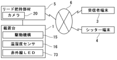
- the monitoring system of this embodiment is a system that distributes image data capturing still or video images indoors to a receiving terminal 3 via a network 6, and includes a camera 61 for capturing still or video images and a lead holding member 5 equipped with an extendable lead 50, a mounting base 1 on which the lead holding member 5 is placed, a drive unit that rotates the lead holding member 5 horizontally and/or vertically, and an operating means for operating the drive unit from the receiving terminal 3 via the network 6.
- the lead holding member 5 is equipped with a winding section 51 that winds up the lead 50 that ties a pet such as a dog around the ring-shaped gripping section, and a camera 61 that takes still or video images of the pet.
- the camera 61 is provided in a camera unit 60 that is detachably arranged at the front of the lead holding member 5.
- the camera unit 60 is equipped with a power switch 62 that activates the camera 61, a microphone 63 for collecting sounds such as cries, and a storage medium for storing image data captured by the camera 61, and is connected to the lead holding member 5 via a USB or the like.
- the camera unit 60 may be provided integrally with the lead holding member 5.
- the camera unit 60 is equipped with wireless communication functions such as wireless LAN and Bluetooth so that it can distribute imaging data to the receiving terminal 3.
- the camera unit 60 connects to a network 6 such as the Internet via a wireless LAN router 7 and communicates with the receiving terminal 3 to distribute still or video imaging data to the receiving terminal 3, while also receiving operation instructions from the receiving terminal 3 to the mobile terminal 2 and mounting base 1.
- the camera unit 60 captures still or video images and distributes the imaging data to the receiving terminal 3.
- the imaging data may include sound picked up by a microphone 64.
- the winding section 51 has the function of automatically winding up the lead 50, and the lead holding member 5 is provided with a locking mechanism 52 for locking the extension and contraction of the lead.
- the lead holding member 5 also has operation buttons 53 for operating the camera 61, etc., a touch panel type screen 54 for displaying still images and videos captured by the camera 61 and the operation status, a vibration mechanism 55 and speaker 56 for transmitting various notifications by vibration and sound, and an LED light 57 for illuminating the subject.
- the lead holding member 5 also has a connection terminal such as a USB that is connected to the mounting base 1, and is designed to charge the internal battery while it is placed on the mounting base 1.
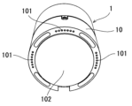
- the mounting base 1 is composed of a disk-shaped base 70 that is placed on the floor or table, a roughly cylindrical rotating part 71 that is provided on the upper side of the base 70 so as to be rotatable relative to the base 70, and a clamping part 72 formed in a groove shape on the upper part of the rotating part 71 in which the lead gripping member 5 can be placed.
- the clamping portion 72 is provided with a connection terminal such as a USB that connects to the lead gripping member 5 when the lead gripping member 5 is placed on it.
- the rotating portion 71 has a built-in drive mechanism 15 such as a stepping motor that rotates the rotating portion 71 horizontally relative to the base portion 70.
- the rotating portion 71 is configured so that the orientation of the camera 61 can be rotated 150° in each direction to the left and right via a gear reduction mechanism.
- the mounting base 1 is provided with a left and right rotation origin sensor for grasping the reference position when rotating the rotating portion 71 relative to the base portion 70.
- the viewing angle of the camera 61 is preferably at least 70° or more in the horizontal direction so that it can capture 360° in the horizontal direction.
- the mounting stand 1 is provided with a temperature and humidity sensor 16 inside the rotating part 71 as a temperature measuring means for measuring the indoor temperature.
- the mounting stand 1 also has a number of infrared LEDs 73 on the outer periphery of the base part 70 as an infrared signal emitting means for emitting infrared signals for operating one or more indoor electrical appliances based on operations from the receiving terminal 3.
- the infrared signal emitting means can be adapted to various products by storing infrared signals corresponding to operations, so long as the electrical appliance has an infrared remote controller.
- the infrared signal emitting means can perform operations such as adjusting the temperature of air conditioning equipment, adjusting the luminance of lighting, and turning lights on and off.
- the mounting base 1 is provided with a security lock switch 74 on the top surface of the rotating part 71 for turning the security lock function ON/OFF. When the security lock function is turned ON, the still images and videos displayed on the receiving terminal 3 are displayed as mosaics.
- the mounting base 1 is also provided with an LED 73 for displaying the status, which is displayed in red when the security lock function is ON, for example.
- the mounting table 1 is equipped with a control device that performs drive control of the stepping motor and control of the infrared signal transmission means, and is controlled based on operation instructions sent from the receiving terminal 3.
- the mounting table 1 receives operation instructions sent from the receiving terminal 3 via the lead gripping member 5.
- the mounting table 1 may be provided with, for example, an adhesive gel sheet on the bottom surface of the base portion 70 as an anti-tipping mechanism, and may be provided with a drive unit that rotates the lead gripping member 5 in the vertical direction.
- the mounting base 1 may be equipped with an ultrasonic transmitter that emits ultrasonic waves of 20 KHz or more to drive away fleas and ticks.
- the ultrasonic transmitter emits ultrasonic waves of 40 KHz and is equipped with a switch to turn the ultrasonic waves ON/OFF.
- the switch is equipped with an LED lighting section so that it is possible to visually determine whether the ultrasonic function is enabled or disabled.
- the receiving terminal 3 is a terminal such as a smartphone, tablet terminal, or personal computer that can be connected to a network 6 such as the Internet.
- the receiving terminal 3 is equipped with dedicated application software for receiving image data captured by the camera 61 of the lead gripping member 5 and for transmitting operation instructions for the lead gripping member 5 and the mounting table 1 to the lead gripping member 5.
- the receiving terminal 3 displays the captured image data received from the camera unit 60 on the screen 30.
- the screen 30 includes a rotation operation unit 31 for rotating the rotating unit 71 of the mounting base 1, a photography operation unit 32 for causing the camera 61 to capture still images, a video capture operation unit 33 for causing the camera 61 to capture video images, a zoom operation unit 34 for controlling the zoom function of the camera 61, a voice operation unit 35 for operating the microphone 63 and speaker 56 of the lead gripping member 5, an air conditioning operation unit 36 for controlling the air conditioning equipment by transmitting infrared signals from the infrared LED 73 provided on the mounting base 1, a lighting operation unit 37 for controlling the lighting by transmitting infrared signals from the infrared LED 73 provided on the mounting base 1, a notification unit 38 for displaying notifications such as abnormalities detected by the lead gripping member 5, and a call unit 39 for contacting the outside.
- the details of each function of the receiving terminal 3 are the same as those of the first embodiment.
- the receiving terminal 3 also includes a function
- the camera unit 60 preferably has a GPS function.
- the GPS function is only active in walking mode when the lead holding member 5 is removed from the mounting base 1, and does not function in monitoring mode when the lead holding member 5 is placed on the mounting base 1.
- the camera unit 60 transmits GPS coordinates to the receiving terminal 3.
- the camera unit 60 records the GPS coordinates in its internal memory.
- the camera unit 60 is capable of taking photographs, taking videos, and delivering streaming videos in real time.
- the camera unit 60 stores the captured image data captured in the walking mode in a storage medium such as a flash memory.
- a storage medium such as a flash memory.
- the camera unit 60 may upload the captured image data stored in the storage medium to cloud storage via the wireless LAN router 7.
- the camera unit 60 deletes the captured images uploaded to the cloud storage from the storage medium.
- the receiving terminal 3 launches the application software and is connected to the camera unit 60 via Bluetooth, it displays thumbnail data of the captured image data stored in the storage medium on the screen 30.
- the receiving terminal 3 taps the thumbnail display on the screen 30, the captured image data of still images and videos stored in the storage medium is downloaded to the receiving terminal 3 via wireless LAN.
- the streaming data of the video is saved in cloud storage from the camera unit 60 via the wireless LAN router 7 or the receiving terminal 3.
- the user can set the receiving terminal 3 to stream videos of, for example, a walk in real time.
- the receiving terminal 3 has a function that allows the user to limit the destination of streaming to receiving terminals 3 of family members or terminals of other users that have the same application software installed.
- the receiving terminal 3 also has a function to allow other users to post content and to accept tips.
- the receiving terminal 3 may be equipped with a live distribution means for setting the video captured by the camera 61 to be distributed live, and a payment means for registering the products and services to be provided and for making payments for the buying and selling of those products and services.
- a live distribution means for setting the video captured by the camera 61 to be distributed live
- a payment means for registering the products and services to be provided and for making payments for the buying and selling of those products and services.
- the sitter matching system of this embodiment is a monitoring system as shown in the first and second embodiments above, in which the receiving terminal 3 is equipped with a sitter recruiting means for recruiting sitters by specifying desired conditions including date and time, a sitter introducing means for introducing sitters who meet the desired conditions, and a requesting means for selecting a sitter to request from among the introduced sitters.
- the sitter matching system of this embodiment also includes a client soliciting means that allows the sitter to solicit clients by specifying contract conditions, including time slots and fees, from the sitter terminal 4, a client introducing means that introduces clients who meet the contract conditions, and a contracting means that selects a client to take on the job from among the introduced clients.
- the sitter matching system displays service options such as dog walking, house sitting, dog care assistance, on-site dog grooming, and dog consultations on the screen 30 of the client's receiving terminal 3.
- the sitter matching system displays options such as a schedule of favorite sitters, sitter recruitment, and sitter search on the screen 30.
- the sitter matching system displays the desired date and time, the number of dogs requested, and whether or not a DogCam (lead holding device) is used on the screen 30.
- the sitter matching system displays a list of sitters who have applied in response to the recruitment on the screen 30. The client can select the desired sitter from the applicants and make a reservation.
- the sitter matching system displays items such as business schedule input, contract terms input, and condition match alerts on the screen of the sitter's sitter terminal 4.
- the sitter matching system searches for sitter postings that meet the conditions and displays a list of postings on the screen. If the sitter sets the condition match alert to ON in the settings on the sitter terminal 4, the sitter matching system will notify the sitter terminal 4 of an alert when a posting that meets the conditions is found.
- the sitter can apply for a sitter posting by checking the details of the posting on the screen of the sitter terminal 4 and tapping "Apply" for the posting they desire.
- the sitter terminal 4 is preferably a mobile terminal such as a smartphone or tablet terminal that can connect to a network 6 such as the Internet.
- Application software for using the sitter matching system is installed on the sitter terminal 4.
- the client When a client leaves a pet such as a dog with a sitter who has been requested to take the pet for a walk, the client also leaves the lead holding member 5 with the sitter, and the client can use the GPS function of the camera unit 60 to check the walk route and current location on the screen 30 of the receiving terminal 3 as shown in FIG. 13.
- the client can also have the camera unit 60 transmit still and video capture data during the walk to the receiving terminal 3, allowing the client to keep track of what is happening during the walk. If the sitter has the lead holding member 5, the sitter may use the lead holding member 5 to take the pet for a walk. If neither the client nor the sitter has the lead holding member 5, the client may start up application software on the sitter terminal and use the GPS and camera functions of the sitter terminal 5.
- pet owners would search for information such as price, service area, available schedules, and sitter ratings themselves, and then make a reservation with a sitter that met their criteria. Meanwhile, sitters had to create websites and spend money on advertising to increase their exposure in order to be found by pet owners.
- This sitter matching system With this sitter matching system, clients simply input their desired conditions and wait; there is no need to search for sitters as in the past. Clients simply need to choose from among the sitters who have applied who seem suitable in terms of both the price and reviews. Furthermore, because this sitter matching system allows sitters to search for requests from clients, there is no need to create a website or spend money on advertising, and they can find work independently. Sitters can independently fill their work schedules during their free time, which leads to increased sales. This sitter matching system solves the issues faced by both clients and sitters, making it possible to achieve a high matching rate.
- the sitter matching system also allows photos taken during walks and walking routes to be compiled as a diary on the application software of the sitter terminal 4, and allows notes to be written in the diary and submitted as a business report.
- the sitter matching system also receives the payment to the sitter when the client reserves the sitter, and when the job is completed, the payment is made to the sitter when the client reviews the sitter on the receiving terminal 3.
- This sitter matching system can be used not only for requests such as walking pets, but also for matching babysitters to look after children and elderly caregivers to look after the elderly.
- the receiving terminal 3 or the sitter terminal 4 has a function of measuring two types of steps, that is, the number of steps taken each day and the number of steps taken while walking a pet, using a pedometer included in the smartphone.
- the receiving terminal 3 or the sitter terminal 4 starts measuring the number of steps taken while walking a pet, and measures the number of steps taken until the walk end button is pressed.
- the terminal screen during the walk displays the elapsed time of the walk, the distance traveled, the number of steps taken, and the calories burned.
- the receiving terminal 3 or the sitter terminal 4 stores the history of walks and displays the history such as the number of steps taken and the calories burned.
Landscapes
- Engineering & Computer Science (AREA)
- Multimedia (AREA)
- Signal Processing (AREA)
- Business, Economics & Management (AREA)
- Tourism & Hospitality (AREA)
- Environmental Sciences (AREA)
- Life Sciences & Earth Sciences (AREA)
- Primary Health Care (AREA)
- General Physics & Mathematics (AREA)
- Marketing (AREA)
- General Health & Medical Sciences (AREA)
- Strategic Management (AREA)
- Physics & Mathematics (AREA)
- General Business, Economics & Management (AREA)
- Human Resources & Organizations (AREA)
- Theoretical Computer Science (AREA)
- Economics (AREA)
- Animal Husbandry (AREA)
- Biodiversity & Conservation Biology (AREA)
- Health & Medical Sciences (AREA)
- Alarm Systems (AREA)
Priority Applications (1)
| Application Number | Priority Date | Filing Date | Title |
|---|---|---|---|
| JP2025505628A JPWO2024185794A1 (https=) | 2023-03-05 | 2024-03-05 |
Applications Claiming Priority (2)
| Application Number | Priority Date | Filing Date | Title |
|---|---|---|---|
| JP2023033273 | 2023-03-05 | ||
| JP2023-033273 | 2023-03-05 |
Publications (1)
| Publication Number | Publication Date |
|---|---|
| WO2024185794A1 true WO2024185794A1 (ja) | 2024-09-12 |
Family
ID=92675226
Family Applications (1)
| Application Number | Title | Priority Date | Filing Date |
|---|---|---|---|
| PCT/JP2024/008396 Ceased WO2024185794A1 (ja) | 2023-03-05 | 2024-03-05 | 見守りシステム、見守りプログラム及びシッターマッチングシステム |
Country Status (2)
| Country | Link |
|---|---|
| JP (1) | JPWO2024185794A1 (https=) |
| WO (1) | WO2024185794A1 (https=) |
Citations (8)
| Publication number | Priority date | Publication date | Assignee | Title |
|---|---|---|---|---|
| JP2001297210A (ja) * | 2000-04-13 | 2001-10-26 | Apeiron Corp | 仕事の仲介方法、ソフトウエア技術のカリキュラム作成方法、仕事の仲介システムおよび仕事の仲介プログラムを記憶した記憶媒体 |
| JP2006019978A (ja) * | 2004-06-30 | 2006-01-19 | Casio Comput Co Ltd | カメラ付き携帯電話装置、カメラ付き携帯電話装置のスタンド、およびカメラ付き携帯電話装置の制御プログラム |
| JP2006135547A (ja) * | 2004-11-04 | 2006-05-25 | Nec Corp | 端末ホルダ |
| JP2006262315A (ja) * | 2005-03-18 | 2006-09-28 | Venture Creator:Kk | 携帯電話機能拡張装置 |
| JP2013074382A (ja) * | 2011-09-27 | 2013-04-22 | Nec Saitama Ltd | 端末装置、異常検出システム、異常検出方法および異常検出プログラム |
| JP2016071569A (ja) * | 2014-09-29 | 2016-05-09 | グリー株式会社 | プログラム、制御方法及び情報処理装置 |
| JP2016146150A (ja) * | 2015-02-06 | 2016-08-12 | 株式会社ソキエ | スマートフォンを用いた見守りシステムのビジネスモデル |
| JP2021129205A (ja) * | 2020-02-13 | 2021-09-02 | 株式会社白紙とロック | 配信システム、ライブ配信装置、ライブ配信方法及びプログラム |
-
2024
- 2024-03-05 WO PCT/JP2024/008396 patent/WO2024185794A1/ja not_active Ceased
- 2024-03-05 JP JP2025505628A patent/JPWO2024185794A1/ja active Pending
Patent Citations (8)
| Publication number | Priority date | Publication date | Assignee | Title |
|---|---|---|---|---|
| JP2001297210A (ja) * | 2000-04-13 | 2001-10-26 | Apeiron Corp | 仕事の仲介方法、ソフトウエア技術のカリキュラム作成方法、仕事の仲介システムおよび仕事の仲介プログラムを記憶した記憶媒体 |
| JP2006019978A (ja) * | 2004-06-30 | 2006-01-19 | Casio Comput Co Ltd | カメラ付き携帯電話装置、カメラ付き携帯電話装置のスタンド、およびカメラ付き携帯電話装置の制御プログラム |
| JP2006135547A (ja) * | 2004-11-04 | 2006-05-25 | Nec Corp | 端末ホルダ |
| JP2006262315A (ja) * | 2005-03-18 | 2006-09-28 | Venture Creator:Kk | 携帯電話機能拡張装置 |
| JP2013074382A (ja) * | 2011-09-27 | 2013-04-22 | Nec Saitama Ltd | 端末装置、異常検出システム、異常検出方法および異常検出プログラム |
| JP2016071569A (ja) * | 2014-09-29 | 2016-05-09 | グリー株式会社 | プログラム、制御方法及び情報処理装置 |
| JP2016146150A (ja) * | 2015-02-06 | 2016-08-12 | 株式会社ソキエ | スマートフォンを用いた見守りシステムのビジネスモデル |
| JP2021129205A (ja) * | 2020-02-13 | 2021-09-02 | 株式会社白紙とロック | 配信システム、ライブ配信装置、ライブ配信方法及びプログラム |
Non-Patent Citations (2)
| Title |
|---|
| PETPILALA: " Exhibition of a prototype of the "PetPilala", in-home pet camera that serves as 2 units)", ([INTERPETS 2022], 26 June 2022 (2022-06-26), pages 1 - 11, XP093207926, Retrieved from the Internet <URL:https://petlinqplus.com/2022interpet/> * |
| TOREPET: "For first-time users. pet sitter search engine", TOREPET.COM, JP, 27 May 2019 (2019-05-27), JP, pages 1 - 6, XP093207936, Retrieved from the Internet <URL:https://torepet.com/first.html> * |
Also Published As
| Publication number | Publication date |
|---|---|
| JPWO2024185794A1 (https=) | 2024-09-12 |
Similar Documents
| Publication | Publication Date | Title |
|---|---|---|
| US10251370B2 (en) | Remote interaction device | |
| JP6749711B2 (ja) | コミュニケーションロボット及びコミュニケーションシステム | |
| CN100409578C (zh) | 家庭安全系统及其监控方法 | |
| JP4483695B2 (ja) | 撮像システム、システム制御方法 | |
| US8134600B2 (en) | Internet direct device | |
| US10194192B2 (en) | Integrated internet camera system and method | |
| JP2005026832A (ja) | 無線カメラネットワークシステム、無線撮影装置 | |
| US20140152835A1 (en) | Remote monitoring system and method for operating the same | |
| CN105278227A (zh) | 照明装置 | |
| WO2024185794A1 (ja) | 見守りシステム、見守りプログラム及びシッターマッチングシステム | |
| US20100228653A1 (en) | Data reproduction device, content delivery system, and content delivery method | |
| JP6286595B2 (ja) | 撮影装置及び撮影システム | |
| JP5772360B2 (ja) | 端末監視装置及び端末監視システム並びにプログラム | |
| JP2002351972A (ja) | ネットワークを利用した監視システム | |
| JP2006115241A (ja) | 特定領域の監視システム | |
| TWI680676B (zh) | 網路攝影設備以及監控系統 | |
| KR101415214B1 (ko) | 사진촬영 로봇의 원격 제어권 획득 및 이양방법 | |
| JP2017212029A (ja) | 照明制御システム及び照明制御方法 | |
| JP5422076B1 (ja) | 遠隔監視システム | |
| JP2006333013A (ja) | 画像監視装置 | |
| WO2025037391A1 (ja) | 認証システムおよびプログラム | |
| JP4310255B2 (ja) | 特定領域の監視システム | |
| JP2006115240A (ja) | 特定領域の監視システム |
Legal Events
| Date | Code | Title | Description |
|---|---|---|---|
| 121 | Ep: the epo has been informed by wipo that ep was designated in this application |
Ref document number: 24767161 Country of ref document: EP Kind code of ref document: A1 |
|
| ENP | Entry into the national phase |
Ref document number: 2025505628 Country of ref document: JP Kind code of ref document: A |
|
| WWE | Wipo information: entry into national phase |
Ref document number: 2025505628 Country of ref document: JP |
|
| NENP | Non-entry into the national phase |
Ref country code: DE |
|
| 122 | Ep: pct application non-entry in european phase |
Ref document number: 24767161 Country of ref document: EP Kind code of ref document: A1 |