WO2024185659A1 - 電気刺激装置 - Google Patents
電気刺激装置 Download PDFInfo
- Publication number
- WO2024185659A1 WO2024185659A1 PCT/JP2024/007664 JP2024007664W WO2024185659A1 WO 2024185659 A1 WO2024185659 A1 WO 2024185659A1 JP 2024007664 W JP2024007664 W JP 2024007664W WO 2024185659 A1 WO2024185659 A1 WO 2024185659A1
- Authority
- WO
- WIPO (PCT)
- Prior art keywords
- electrical stimulation
- electrode
- user
- stimulation device
- unit
- Prior art date
- Legal status (The legal status is an assumption and is not a legal conclusion. Google has not performed a legal analysis and makes no representation as to the accuracy of the status listed.)
- Ceased
Links
Images





Classifications
-
- A—HUMAN NECESSITIES
- A61—MEDICAL OR VETERINARY SCIENCE; HYGIENE
- A61N—ELECTROTHERAPY; MAGNETOTHERAPY; RADIATION THERAPY; ULTRASOUND THERAPY
- A61N1/00—Electrotherapy; Circuits therefor
- A61N1/18—Applying electric currents by contact electrodes
- A61N1/32—Applying electric currents by contact electrodes alternating or intermittent currents
- A61N1/36—Applying electric currents by contact electrodes alternating or intermittent currents for stimulation
- A61N1/36003—Applying electric currents by contact electrodes alternating or intermittent currents for stimulation of motor muscles, e.g. for walking assistance
-
- A—HUMAN NECESSITIES
- A61—MEDICAL OR VETERINARY SCIENCE; HYGIENE
- A61F—FILTERS IMPLANTABLE INTO BLOOD VESSELS; PROSTHESES; DEVICES PROVIDING PATENCY TO, OR PREVENTING COLLAPSING OF, TUBULAR STRUCTURES OF THE BODY, e.g. STENTS; ORTHOPAEDIC, NURSING OR CONTRACEPTIVE DEVICES; FOMENTATION; TREATMENT OR PROTECTION OF EYES OR EARS; BANDAGES, DRESSINGS OR ABSORBENT PADS; FIRST-AID KITS
- A61F7/00—Heating or cooling appliances for medical or therapeutic treatment of the human body
- A61F7/007—Heating or cooling appliances for medical or therapeutic treatment of the human body characterised by electric heating
-
- A—HUMAN NECESSITIES
- A61—MEDICAL OR VETERINARY SCIENCE; HYGIENE
- A61N—ELECTROTHERAPY; MAGNETOTHERAPY; RADIATION THERAPY; ULTRASOUND THERAPY
- A61N1/00—Electrotherapy; Circuits therefor
- A61N1/02—Details
- A61N1/04—Electrodes
-
- A—HUMAN NECESSITIES
- A61—MEDICAL OR VETERINARY SCIENCE; HYGIENE
- A61N—ELECTROTHERAPY; MAGNETOTHERAPY; RADIATION THERAPY; ULTRASOUND THERAPY
- A61N1/00—Electrotherapy; Circuits therefor
- A61N1/02—Details
- A61N1/04—Electrodes
- A61N1/0404—Electrodes for external use
- A61N1/0408—Use-related aspects
- A61N1/0452—Specially adapted for transcutaneous muscle stimulation [TMS]
-
- A—HUMAN NECESSITIES
- A61—MEDICAL OR VETERINARY SCIENCE; HYGIENE
- A61N—ELECTROTHERAPY; MAGNETOTHERAPY; RADIATION THERAPY; ULTRASOUND THERAPY
- A61N1/00—Electrotherapy; Circuits therefor
- A61N1/02—Details
- A61N1/04—Electrodes
- A61N1/0404—Electrodes for external use
- A61N1/0472—Structure-related aspects
- A61N1/0484—Garment electrodes worn by the patient
-
- A—HUMAN NECESSITIES
- A61—MEDICAL OR VETERINARY SCIENCE; HYGIENE
- A61N—ELECTROTHERAPY; MAGNETOTHERAPY; RADIATION THERAPY; ULTRASOUND THERAPY
- A61N1/00—Electrotherapy; Circuits therefor
- A61N1/18—Applying electric currents by contact electrodes
- A61N1/32—Applying electric currents by contact electrodes alternating or intermittent currents
- A61N1/36—Applying electric currents by contact electrodes alternating or intermittent currents for stimulation
-
- A—HUMAN NECESSITIES
- A61—MEDICAL OR VETERINARY SCIENCE; HYGIENE
- A61F—FILTERS IMPLANTABLE INTO BLOOD VESSELS; PROSTHESES; DEVICES PROVIDING PATENCY TO, OR PREVENTING COLLAPSING OF, TUBULAR STRUCTURES OF THE BODY, e.g. STENTS; ORTHOPAEDIC, NURSING OR CONTRACEPTIVE DEVICES; FOMENTATION; TREATMENT OR PROTECTION OF EYES OR EARS; BANDAGES, DRESSINGS OR ABSORBENT PADS; FIRST-AID KITS
- A61F7/00—Heating or cooling appliances for medical or therapeutic treatment of the human body
- A61F7/007—Heating or cooling appliances for medical or therapeutic treatment of the human body characterised by electric heating
- A61F2007/0071—Heating or cooling appliances for medical or therapeutic treatment of the human body characterised by electric heating using a resistor, e.g. near the spot to be heated
Definitions
- the present invention relates to an electrical stimulation device.
- the electrical stimulation device has an electrode part that comes into contact with the user's body, and is configured to apply electrical stimulation to the user's muscles by passing a weak current through the electrode part.
- the electrode part of the electrical stimulation device may be made of conductive cloth to prevent corrosion caused by the passage of electricity (for example, Patent Document 1).
- conductive cloth for the electrodes of an electrical stimulation device
- conductive cloth that is wet with water gives a cold sensation to the user, and so when the user wears the electrical stimulation device, the conductive cloth touching the user's body can cause the user to feel uncomfortable.
- the present invention was made in consideration of this background, and aims to provide an electrical stimulation device that can deliver electrical stimulation to the user's muscles even if no moisture is applied to the electrode parts before use, and that can reduce the discomfort felt when worn.
- One aspect of the present invention is an electrical stimulation device configured to be able to apply electrical stimulation to a user's muscle
- the electrical stimulation device includes an electrode portion that is conductive and is provided at a position that can contact the body of the user; an electrode holder configured to hold the electrode; A control unit configured to supply power to the electrode unit to apply electrical stimulation to the user's muscles,
- the electrode portion is in an electrical stimulation device that is configured to be able to retain moisture generated from the user's body between the electrode portion and the user's body.
- the electrode portion of the electrical stimulation device is configured to be able to retain moisture, such as sweat, dissipated from the user's body between the electrode portion and the user's body. Therefore, the electrical stimulation device can retain moisture generated from the user's body between the electrode portion and the body, reducing the electrical resistance between the electrode portion and the body. As a result, even if moisture is not attached to the electrode portion before use, electrical stimulation can be easily applied to the user's muscles.
- the electrical stimulation device does not require moisture to be applied to the electrode parts before use, the user can wear the device without applying moisture to the electrode parts, thereby reducing the discomfort felt by the user when wearing the device. Furthermore, in this case, since there is no need to apply moisture to the electrode parts before using the electrical stimulation device, the complexity of the preparation work before using the electrical stimulation device can be reduced. In addition, since the moisture held between the electrode parts and the user's body originates from the user's body, it has a temperature similar to the user's body temperature. Therefore, it is easy to avoid the user feeling cold while using the electrical stimulation device.
- an electrical stimulation device that can apply electrical stimulation to the user's muscles even if moisture is not attached to the electrode portion, thereby reducing the discomfort felt when wearing the device.
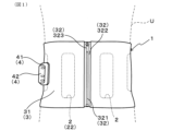
- FIG. 1 is an explanatory diagram showing an electrical stimulation device in a worn state in a first embodiment.
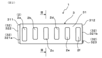
- FIG. 2 is a plan view of the inner surface of the electrical stimulation device according to the first embodiment.
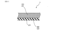
- FIG. 3 is a partial cross-sectional view taken along line III-III in FIG.
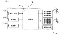
- FIG. 4 is a block diagram of the electrical stimulation device according to the first embodiment.
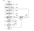
- FIG. 5 is a flowchart of the operation of the electrical stimulation device in the first embodiment.
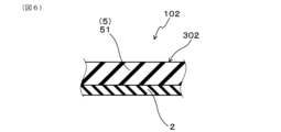
- FIG. 6 is a cross-sectional view of a main part of an electrical stimulation device including a heat retaining portion in a second embodiment.
- FIG. 7 is a cross-sectional view of a main part of an electrical stimulation device including a heating unit according to a third embodiment.
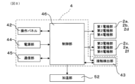
- FIG. 8 is a block diagram of an electrical stimulation device according to a third embodiment.
- FIG. 9 is a flowchart of the operation of the electrical stimulation device in the third embodiment.
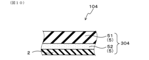
- FIG. 10 is a cross-sectional view of a main part of an electrical stimulation device including both a heat retaining section and a heating section in a fourth embodiment.
- FIG. 11 is a cross-sectional view of an electrode portion including a power-receiving layer in the fifth embodiment.
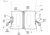
- FIG. 12 is an explanatory diagram of a state in which an electrical stimulation device including a circumference adjustment member 6 in Example 6 is worn on the body of a user.
- FIG. 13 is a plan view of the inner surface of the electrical stimulation device in Example 6.
- 14 is a partial cross-sectional view taken along line XIV-XIV in FIG.
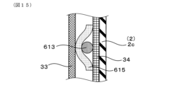
- 15 is a partial cross-sectional view taken along line XV-XV in FIG.
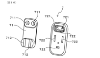
- FIG. 16 is an exploded perspective view of the cord clip according to the sixth embodiment.
- the electrical stimulation device has at least one pair of electrode parts.
- the electrode parts are conductive and are provided in positions that allow contact with the user's body.
- the electrical stimulation device applies a voltage so that a potential difference occurs between these electrode parts, thereby forming a circular current path that includes the electrode parts, the user's body, and the control unit, and can apply electrical stimulation to the user's muscles.
- the number and arrangement of the electrode parts are not particularly limited, and can be in a form that corresponds to the shape of the electrical stimulation device and the position of the muscle to which electrical stimulation is to be applied. From the viewpoint of efficiently applying electrical stimulation to the user's muscles, it is preferable that the number of electrode parts is two or more pairs.
- the surface resistivity of the electrode portion is preferably 100 ⁇ / ⁇ or less, and more preferably 80 ⁇ / ⁇ or less.
- the surface of the electrode unit that comes into contact with the user's body is preferably smooth.
- smooth refers to a state in which there are no irregularities, gaps, holes, etc. when observed visually.
- the electrode section is configured to be able to retain moisture generated from the user's body between the electrode section and the user's body. Therefore, when the user is wearing the electrical stimulation device, the electrical stimulation device can retain moisture generated from the user's skin between the user's body and the electrode section. As a result, even if moisture is not attached to the electrode section before use of the electrical stimulation device, electrical stimulation can be applied to the user's muscles. Furthermore, even if the electrical stimulation device is used without attaching moisture to the electrode section, the electrical stimulation device can apply electrical stimulation to the user's muscles by utilizing the moisture retained between the electrode section and the user's body. Therefore, the electrical stimulation device can reduce the complexity of the preparation work to be performed before use. Note that moisture generated from the user's body includes moisture that naturally evaporates from the skin and sweat secreted from the skin.
- the moisture permeability of the electrode part is preferably 5000 g/( m2 ⁇ 24 hours) or less, more preferably 3000 g/( m2 ⁇ 24 hours) or less, and even more preferably 1000 g/( m2 ⁇ 24 hours) or less.
- moisture such as sweat generated from the user's skin is more easily retained between the user's body and the electrode part, so that the above-mentioned effect can be obtained more reliably.
- the electrode portion may be composed of a single layer, or may be composed of multiple layers laminated together.
- the layer constituting the electrode portion is conductive and has low moisture permeability.
- the material constituting the electrode portion may be, for example, a conductive rubber or elastomer such as conductive ethylene propylene rubber, conductive polyurethane, or conductive silicone.
- the electrode portion when the electrode portion is composed of multiple layers, at least one of these layers that comes into contact with the user's body needs to be conductive. Furthermore, when the electrode portion is composed of multiple layers, at least one of these layers needs to have low moisture permeability. More specifically, when the electrode portion is composed of multiple layers, the material that makes up the layer that comes into contact with the user's body can be, for example, a cloth made of conductive fibers, or the aforementioned conductive rubber or elastomer. Furthermore, when the electrode portion is composed of multiple layers, the material that makes up the layer with low moisture permeability can be, for example, rubber or elastomer.
- the electrode section preferably has a wrap layer made of rubber or elastomer.
- moisture such as sweat generated by the user's body can be retained between the user's body and the wrap layer. This makes it easier to reduce the electrical resistance between the electrode section and the user's body, and allows for efficient electrical stimulation of the user's muscles.
- the wrap layer may or may not be conductive. If the wrap layer is not conductive, a conductive layer can be provided on the surface of the electrode unit that comes into contact with the user's body, and electrical stimulation can be applied to the user's body by supplying power directly from the control unit to the conductive layer.
- the wrap layer when the wrap layer is provided at a position where it comes into contact with the user's body, it is preferable that the wrap layer is made of conductive rubber or elastomer.
- the wrap layer can retain moisture generated from the user's body between the wrap layer and the user's body, and can provide electrical stimulation to the user's muscles via the wrap layer.
- the structure of the electrode unit can be simplified, since the wrap layer alone can retain moisture between the user's body and the electrode unit, and can provide electrical stimulation to the user's muscles.
- the thickness of the wrap layer can be set appropriately, for example, within the range of 0.3 mm or more and 5 mm or less.
- the electrode section may further have a power receiving layer made of metal that receives power supplied from the control section, and the power receiving layer may be provided on the back surface of the wrap layer that comes into contact with the user's body. Because the power receiving layer is made of metal, the electrical resistance of the power receiving layer can be easily made lower than that of the wrap layer. By supplying power to the power receiving layer, which has such low electrical resistance, localized bias in the voltage applied to the electrode section can be further reduced, and the voltage can be applied more uniformly to the user's body in contact with the electrode section. As a result, the desired electrical stimulation can be more easily applied to the user's muscles.
- the metal constituting the power receiving layer may be, for example, copper, silver, or gold, which have excellent electrical conductivity.
- the power receiving layer may also be made of metal fibers, such as copper fibers or silver fibers, or may be made of metal foil, such as copper foil or silver foil. From the viewpoint of increasing the flexibility of the power receiving layer and making it easier to adhere the power receiving layer to the wrap layer, it is preferable that the power receiving layer be made of metal fibers.
- the electrode units in the electrical stimulation device are held by an electrode holding unit.
- the electrode holding unit may be configured so that the multiple electrode units can maintain a predetermined positional relationship.
- the electrode holding unit may be configured so that it can hold the electrode units in a detachable state, or it may be configured so that it can hold the electrode units in a non-removable state.
- the electrode holding portion may be composed of a single layer, or may be composed of multiple layers laminated together. Furthermore, the material constituting the electrode holding portion is not particularly limited, and various materials such as cloth, rubber, and elastomers can be used. From the viewpoint of more easily bringing the electrode portion into close contact with the user's body, it is preferable that the electrode holding portion is elastic and configured so that the user can stretch it when wearing it.
- the electrode holding part may have a shape that allows the user to wear it, for example. More specifically, the electrode holding part may have a shape that covers the upper half of the user's body, such as a shirt, or may have a shape that covers the lower half of the user's body, such as tights or leggings. Furthermore, the electrode holding part may have a belt-like or annular shape that covers the abdomen, legs, arms, etc. of the user. When the electrode holding part has a belt-like shape, the electrode holding part may have an engagement part configured to be able to engage one end and the other end. Furthermore, the electrode holding part may be configured so that one end and the other end can be engaged by a part or the like separate from the electrode holding part.
- the electrode holding portion may also have, for example, a suction cup or adhesive, and may be configured so that the electrical stimulation device can be attached to a desired position on the user's body via these parts. Furthermore, if the surface of the electrode portion is adhesive, the electrode holding portion may be configured so that the electrical stimulation device can be attached to a desired position on the user's body via the electrode portion.
- the electrode holding section preferably further includes a moisturizing section configured to be able to retain moisture generated from the user's body between the electrical stimulation device and the user's body.
- a moisturizing section configured to be able to retain moisture generated from the user's body between the electrical stimulation device and the user's body.
- moisture generated from the user's body can be retained between the electrical stimulation device and the user's body, and the dissipation of moisture to the outside of the electrical stimulation device can be suppressed.
- moisture inside the electrical stimulation device moisture is more easily retained between the electrode section and the user's body. As a result, electrical stimulation can be applied to the user's body more easily.
- the number and positions of the moisturizing parts provided on the electrode holding part can take various forms.
- the number of moisturizing parts provided on the electrode holding part may be one, or two or more.
- the moisturizing part may be provided, for example, in a position that covers the electrode part, or in a position that is separate from the electrode part.
- the moisturizing part may be provided so as to cover one electrode part, or so as to cover multiple electrode parts.
- the moisturizing section be provided in a position that covers at least a portion of the electrode section in the electrode holding section, and it is more preferable that the moisturizing section be provided in a position that covers the entire electrode section.
- the moisture permeability of the moisturizing portion is preferably 5000 g/( m2 ⁇ 24 hours) or less, more preferably 3000 g/( m2 ⁇ 24 hours) or less, and even more preferably 1000 g/( m2 ⁇ 24 hours) or less.
- moisture such as sweat generated from the user's skin is more easily retained between the user's body and the electrical stimulation device, so that the above-mentioned effect can be obtained more reliably.
- the moisturizing portion has a layer made of rubber or elastomer.
- rubber or elastomers used in the moisturizing portion include chloroprene rubber and polyurethane.
- the control unit of the electrical stimulation device is configured to be able to apply electrical stimulation to the user's muscles by supplying power to the electrode unit.
- the form of electrical stimulation applied by the control unit is not particularly limited and can take various forms.
- the control unit may be configured to apply pulsed electrical stimulation to the user's muscles by switching between supplying and stopping power to the electrode unit.
- the control unit may also be configured to apply periodic electrical stimulation to the user's muscles by periodically changing the potential of the electrode unit.
- the control unit may be configured to control the operation of the entire electrical stimulation device in addition to switching between supplying and stopping power to the electrode unit.
- the operation of the control unit can be realized, for example, by an electronic circuit or a program stored in a microcomputer.
- the electrical stimulation device preferably has a sweat promotion means configured to promote sweating from the user's body.
- the sweat promotion means can more easily generate moisture such as sweat from the user's body.
- the sweat promotion means can then retain the moisture generated from the user's body between the electrode unit and the user's body.
- the effect of promoting sweating by the sweat promotion means and the effect of retaining moisture by the electrode unit act synergistically, making it easier to achieve a state in which electrical stimulation can be applied to the user's muscles.
- the sweat promotion means of the electrical stimulation device may take various forms as long as it is configured to promote sweating from the part of the user's body covered by the electrode part.
- the sweat promotion means may have a heat retention part provided in a position covering at least a part of the electrode part in the electrode holding part, and the heat retention part may be configured to maintain the temperature of the part covered by the heat retention part at or above the temperature of the surroundings of the part. By maintaining the temperature of the part covered by the heat retention part at or above the temperature of the surroundings, the heat retention part can be expected to promote sweating from the part covered by the heat retention part.
- the heat retaining part may be composed of a single layer or multiple layers.
- the heat retaining part may be composed of a single type of material or multiple types of materials.
- the heat retaining part may be provided in a position that covers a part of the electrode part, may be provided in a position that covers the entire electrode part, or may be provided over the entire electrode holding part. From the viewpoint of more reliably obtaining the above-mentioned effect of the heat retaining part, it is preferable that the heat retaining part is provided in a position that covers at least the entire electrode part, and it is more preferable that the heat retaining part is provided over the entire electrode holding part.
- the moisturizing part may be provided so as to cover one electrode part, or may be provided so as to cover multiple electrode parts.
- the heat retention rate of the heat retaining part is preferably 30% or more, more preferably 40% or more, and even more preferably 50% or more.
- the temperature of the part covered by the heat retaining part can be kept at a higher temperature. As a result, it is expected that sweating from the user's body will be further promoted.
- the heat retention rate of the heat retaining part mentioned above is a value measured by the method specified in JIS L1096:2010.
- the moisture permeability of the heat retaining part is preferably 5000 g/( m2 ⁇ 24 hours) or less, more preferably 3000 g/( m2 ⁇ 24 hours) or less, and even more preferably 1000 g/( m2 ⁇ 24 hours) or less.
- the dissipation of moisture from between the electrical stimulation device and the user's body to the outside of the electrical stimulation device is less likely to occur.
- the effect of suppressing the dissipation of moisture by the heat retaining part and the effect of promoting sweating described above act synergistically, so that the time until a sufficient amount of moisture is retained between the electrode part and the user's body can be further shortened. As a result, the time until the application of electrical stimulation to the muscle can be easily shortened after the user wears the electrical stimulation device.
- the moisture permeability mentioned above is a value measured using the method specified in JIS Z0208-1976.
- the heat retention portion contains rubber or elastomer. That is, the heat retention portion may have a single layer structure made of rubber or elastomer. Also, the heat retention portion may have a multi-layer structure, for example, in which a layer made of rubber or elastomer is laminated on the surface of a layer made of fiber. As the rubber or elastomer contained in the heat retention portion, for example, chloroprene rubber, polyurethane, etc. can be used.
- the sweat promotion means may also have a heating section configured to be able to heat the user's body.
- the heating section can raise the temperature of the user's body surface, easily promoting sweating from the user's skin.
- the time required for a sufficient amount of moisture to be retained between the electrode section and the user's body can be shortened, and a state in which electrical stimulation can be applied can be achieved in a shorter time.
- the sweat promotion means may have either a heat retaining section or a heating section, or may have both. From the viewpoint of further promoting sweating from the user's body, it is preferable that the sweat promotion means has both a heat retaining section and a heating section.
- the heating section increases the temperature of the user's body surface
- the heat retaining section inhibits a decrease in the body surface temperature, making it easier to maintain the body surface temperature increased by the heating section.
- the effects of the heating section and the heat retaining section act synergistically to further promote sweating from the user's body.
- the arrangement of the heating unit in the electrical stimulation device may take various forms.
- the heating unit may be arranged over the entire electrode holding unit, or may be arranged on a part of the electrode holding unit.
- the heating unit may also be arranged on the inner surface of the electrode holding unit, i.e., on the surface on which the electrode unit is provided, or on the outer surface of the electrode holding unit, i.e., on the back surface of the surface on which the electrode unit is provided.
- the electrode unit may be configured to be capable of heating the user's body, and may serve as an electrode unit that also serves as a heating unit. From the viewpoint of more efficiently heating the user's body, it is preferable that the heating unit be arranged on the inner surface of the electrode holding unit.
- the electrical stimulation device has both a heat retaining unit and a heating unit as a sweat promoting means, it is preferable that the heating unit be arranged closer to the user's body than the heat retaining unit.
- the method of heating the user's body in the heating unit can take various forms.
- the heating unit may have a moisture absorbing heat generating material that generates heat by reacting with moisture, or a material such as iron powder that generates heat by reacting with oxygen.
- the heating unit may also be a heater configured to generate heat using power supplied from the control unit.
- the heating unit may also have a medicine such as capsaicin.
- the heating unit is configured to be able to generate heat using power supplied from the control unit. More specifically, such a heating unit may be a heater provided in the electrical stimulation device. In addition, by configuring the electrode unit to be able to generate heat using power supplied from the control unit, it is also possible to use the electrode unit as the heating unit.
- the timing at which the control unit supplies power to the heating unit and causes the heating unit to generate heat can take various forms.
- the control unit may be configured to supply power to the heating unit simultaneously with the operation of the electrical stimulation device.
- the control unit may also be configured to supply power to the heating unit while electrical stimulation is being applied to the user's body.
- the control unit may be configured to supply power to the heating unit in response to the user's operation.
- the control unit is preferably configured to supply power to the heating unit to generate heat, and then, when a predetermined condition is met, supply power to the electrode unit to apply electrical stimulation to the user's body.
- the heating unit can promote sweating from the user's skin before applying electrical stimulation to the user's muscles, so that electrical stimulation can be applied to the user's muscles with a sufficient amount of moisture retained between the electrode unit and the user's body. This makes it possible to apply electrical stimulation to the user's muscles more reliably.
- the conditions for starting the supply of power to the electrode unit after the control unit has supplied power to the heating unit can take various forms. For example, it is generally believed that the amount of sweat produced by the user's body increases the longer the time that has elapsed since heating by the heating unit began. Therefore, the control unit may be configured to start supplying power to the electrode unit when a preset time has elapsed from the time when power supply to the heating unit began. In this case, the time from the start of power supply to the heating unit to the start of power supply to the electrode unit may be stored in advance in the control unit, or may be a value set by the user by operating the control unit.
- control unit may be configured to be able to measure at least one of the user's body temperature, body surface temperature, and electrode unit temperature, and may be configured to start supplying power to the electrode unit when the temperature measured by the control unit exceeds a preset temperature after starting the supply of power to the heating unit.
- control unit is configured to be able to measure the electrical resistance between the electrode unit and the user's body, and may be configured to start supplying power to the electrode unit when the electrical resistance between the electrode unit and the user's body falls below a preset threshold value after starting the supply of power to the heating unit.
- control unit can directly measure the amount of sweat from the body
- the power supply to the heating unit and the electrode unit can be controlled based on the amount of sweat measured by the control unit.
- control unit may have a moisture sensor configured to measure the amount of moisture on the user's skin surface, and may be configured to start supplying power to the electrode unit when the amount of moisture on the user's skin surface exceeds a preset threshold after starting the supply of power to the heating unit.
- control unit may be configured to be capable of communicating with a wearable device configured to acquire vital data such as the user's body temperature and sweat rate, and may be configured to be capable of controlling the power supply to the heating unit and the electrode unit based on the data acquired by the wearable device.
- the electrical stimulation device 1 of this embodiment is configured to be capable of applying electrical stimulation to the muscles of a user U.
- the electrical stimulation device 1 has an electrode unit 2 that is conductive and provided at a position that allows contact with the body of the user U, an electrode holding unit 3 configured to hold the electrode unit 2, and a control unit 41 configured to supply power to the electrode unit 2 to apply electrical stimulation to the muscles of the user U.
- the electrode unit 2 is configured to be capable of holding moisture generated from the body of the user U between the electrode unit 2 and the body of the user U.
- the electrode holding portion 3 of the electrical stimulation device 1 is configured so that it can be attached to the abdomen of a user U. More specifically, the electrode holding portion 3 has a fabric portion 31 made of stretchable cloth. As shown in FIG. 2, the fabric portion 31 has a belt-like shape that is rectangular when unfolded.
- the first longitudinal end 311 of the fabric portion 31 is provided with one element 321a of the fastener 32 and a tape 322 for preventing contact between the element 321 and the body of the user U, and the second end 312 is provided with the other element 321b of the fastener 32 and a slider 323.
- the fastener 32 can be closed with the electrode holding portion 3 wrapped around the abdomen of the user U with the electrode portion 2 in contact with the body of the user U.
- three pairs of electrodes 2 (2a to 2f) are provided on the inner surface of the fabric portion 31 of the electrode holding portion 3, that is, on the surface facing the body of the user U. These electrodes 2 are arranged so that they are equally spaced from each other in the longitudinal direction of the electrode holding portion 3.
- the electrode 2 located at the leftmost position in FIG. 2 is referred to as the first electrode 2a
- the electrode 2 to the right of the first electrode 2a is referred to as the second electrode 2b
- the electrode 2 to the right of the second electrode 2b is referred to as the third electrode 2c, etc.
- the second electrode 2b and the fifth electrode 2e are positioned to face the user's oblique abdominal muscle.
- the third electrode 2c and the fourth electrode 2d are positioned to face the lower part of the user's latissimus dorsi muscle.
- the surface 21 of the electrode part 2 in this example that comes into contact with the body of the user U is smooth.
- a control unit 4 including a control unit 41 is detachably attached to the outer surface of the electrode holding portion 3, i.e., the back surface of the surface having the electrode portion 2.
- An operation panel 42 is provided on the surface of the control unit 4 to enable the user U to operate the electrical stimulation device 1.
- the control unit 4 is configured so that the user U can apply electrical stimulation to the muscles of the user U by operating the electrical stimulation device 1 via the operation panel 42.
- the control unit 4 in this example has a control unit 41, an operation panel 42, a contact detection unit 43, and a power supply unit 44.
- the control unit 41 is connected to the operation panel 42, the contact detection unit 43, the power supply unit 44, and the electrode unit 2, and is configured to be able to control the operation of the entire electrical stimulation device 1, including the supply of power to the electrode unit 2.
- the control unit 41 may be composed of, for example, an electronic circuit or a microcomputer.
- the control unit 41 in this example is also configured to apply a voltage to the electrode unit 2 according to a pre-stored exercise control program, and to apply electrical stimulation having a predetermined pattern to the muscles of the user U.
- exercise control programs include an exercise control program aimed at muscle hypertrophy and an exercise control program aimed at fat burning.
- the exercise control program aimed at muscle hypertrophy is configured to apply pulsed electrical stimulation, mainly having a frequency of 20 Hz, to the muscles for a predetermined period of time.
- pulsed electrical stimulation mainly having a frequency of 20 Hz
- Such an exercise control program is used for resistance training, in which the muscles are intentionally moved at a relatively slow pace while the muscles are forcibly moved by electrical stimulation from the electrical stimulation device 1.
- the exercise control program aimed at fat burning is configured to apply pulsed electrical stimulation, mainly having a frequency lower than 20 Hz, preferably a frequency of 4 to 10 Hz, to the muscles for a predetermined period of time.
- Such an exercise control program is used for hybrid training, in which anaerobic exercise is performed while the muscles are forcibly moved by electrical stimulation from the electrical stimulation device 1, and for cardio training, in which aerobic exercise such as on an exercise bike (registered trademark) is performed while the muscles are forcibly moved.
- the control unit 41 may be configured to be able to implement one type of exercise control program, or may be configured to be able to select and implement one type of exercise control program from multiple types of exercise control programs.
- the control unit 41 in this example is configured to be able to select and implement one of two types of exercise control programs, an exercise control program aimed at muscle hypertrophy and an exercise control program aimed at fat burning.
- control unit 41 The specific operation of the control unit 41 will be described later.
- the operation panel 42 has a switch configured to generate an operation signal used to operate the electrical stimulation device 1.
- the operation signal generated by the switch is input to the control unit 41. This allows the user U to control the operation of the electrical stimulation device 1 via the operation panel 42.
- the operation signals input from the operation panel 42 include, for example, a signal to start applying electrical stimulation, a signal to stop applying electrical stimulation, a signal to change the intensity of the electrical stimulation, a signal to change the exercise control program, and the like. These operation signals may be configured to be generated by a single switch. Also, a separate switch may be provided for each type of operation signal.
- the contact detection unit 43 is connected to the control unit 41 and the electrode unit 2, and is configured to distinguish between a state in which the electrode unit 2 is in contact with the body of the user U and a state in which the electrode unit 2 is separated from the body of the user U, and to notify the control unit 41 of whether the electrode unit 2 is in contact with the body of the user U when the electrode unit 2 is in contact with the body of the user U.
- the contact detection unit 43 may have, for example, a current sensor that measures the current flowing through the electrode unit 2. When the electrode unit 2 is in contact with the body of the user U, a current flows through a current path including the electrode unit 2 and the body of the user U when a voltage is applied to the electrode unit 2.
- the contact detection unit 43 can notify the control unit 41 of whether the electrode unit 2 is in contact with the body of the user U by inputting the magnitude of the current measured by the current sensor to the control unit 41, for example.
- the power supply unit 44 is connected to the control unit 41 and is configured to be able to supply the power necessary for the operation of the control unit 41.
- the control unit 41 is also configured to distribute the power supplied from the power supply unit 44 to each part of the electrical stimulation device 1 and to operate each part of the electrical stimulation device 1.
- the specific form of the power supply unit 44 is not particularly limited.
- the power supply unit 44 may be a primary battery, or a power storage device such as a secondary battery or a capacitor.
- the control unit 4 may have a charging terminal for charging the power storage device.
- the power storage device may also be configured to be charged by a non-contact charging system.
- the control unit 4 may further include a communication section 45 configured to be capable of communicating with an external device.
- the content of the communication in the communication section 45 is not particularly limited.
- the communication section 45 may be configured to be capable of transmitting data stored in the control section 41 and training history to an external device.
- the communication section 45 may be configured to be capable of receiving commands related to the operation of the electrical stimulation device 1 and changes to setting information from the external device.
- the communication section 45 may be configured to be capable of wired communication with the external device, or may be configured to be capable of wireless communication.
- step S1 the user U operates the operation panel 42 while wearing the electrical stimulation device 1 to activate the electrical stimulation device 1 (step S1).
- the user U operates the operation panel 42 as necessary to select the type of exercise control program (step S2).
- the control unit 41 applies a pulsed voltage to the electrode unit 2 (step S3). At this time, the control unit 41 applies the voltage so that the polarity of the first electrode unit 2a, the second electrode unit 2b, and the fourth electrode unit 2d becomes a first polarity, and the polarity of the third electrode unit 2c, the fifth electrode unit 2e, and the sixth electrode unit 2f becomes a second polarity different from the first polarity.
- the contact detection unit 43 measures the current flowing through the electrode unit 2 when the voltage is applied in step S3 (step S4).
- a circular current path including the first electrode 2a, the sixth electrode 2f, and the body of the user U, a circular current path including the second electrode 2b, the fifth electrode 2e, and the body of the user U, and a circular current path including the third electrode 2c, the fourth electrode 2d, and the body of the user U are formed. Therefore, when a voltage is applied to the electrode 2 in step S3, a current flows through these current paths.
- the control unit 41 can determine whether or not the electrode 2 is in contact with the body of the user U based on the magnitude of the current flowing through the electrode 2 (step S5).
- step S5 If it is determined in step S5 that the electrode unit 2 is separated from the body of the user U (step S5, "No"), the control unit 41 determines whether the time elapsed since step S1 has exceeded a preset contact waiting time (step S51).
- step S51 if the time elapsed since step S1 is equal to or less than the contact waiting time (step S51, "No"), the control unit 41 performs steps S3, S4, and S5 again. On the other hand, in step S51, if the time elapsed since step S1 is longer than the contact waiting time (step S51, "Yes"), the control unit 41 determines that the electrical stimulation device 1 has been operated erroneously, and stops the operation of the electrical stimulation device 1.
- step S5 If it is determined in step S5 that the electrode unit 2 is in contact with the body of the user U (step S5, "Yes"), the control unit 41 supplies power to the electrode unit 2 according to the motion control program and applies electrical stimulation to the muscles of the user U (step S6).
- step S6 Similar to step S3, the control unit 41 applies a voltage to the electrode unit 2 so that the polarity of the first electrode unit 2a, the second electrode unit 2b, and the fourth electrode unit 2d shown in FIG. 2 becomes a first polarity, and the polarity of the third electrode unit 2c, the fifth electrode unit 2e, and the sixth electrode unit 2f becomes a second polarity different from the first polarity, thereby applying electrical stimulation to the muscles of the user U.
- the control unit 41 also determines whether a preset termination condition is met while the electrical stimulation is being applied (step S7). Examples of termination conditions include the end of the exercise control program, at least a portion of the electrode unit 2 being separated from the body of the user U, and the user U issuing an instruction to stop the exercise control program. If the termination condition is not met (step S7, "No"), the control unit 41 continues to apply the electrical stimulation. On the other hand, if the termination condition is met, the control unit 41 stops the operation of the electrical stimulation device 1 (step S7, "Yes").
- the electrode unit 2 in the electrical stimulation device 1 of this example is configured to be able to retain moisture such as sweat dissipated from the body of the user U between the electrode unit 2 and the body of the user U. Therefore, the electrical stimulation device 1 can retain moisture generated from the body of the user U between the electrode unit 2 and the body, reducing the electrical resistance between the electrode unit 2 and the body. As a result, even if moisture is not attached to the electrode unit 2 before use, electrical stimulation can be easily applied to the muscles of the user U.
- the electrical stimulation device 1 does not require moisture to be applied to the electrode portion 2 before use, the user U can wear the device without applying moisture to the electrode portion 2, thereby reducing the discomfort felt by the user U when wearing the device. Furthermore, in this case, the task of applying moisture to the electrode portion 2 before using the electrical stimulation device 1 is not required, so the complexity of the preparation work before using the electrical stimulation device 1 can be reduced. In addition, since the moisture held between the electrode portion 2 and the body of the user U originates from the body of the user U, it has a temperature approximately equal to the body temperature of the user U. Therefore, it is easy to avoid the user U feeling cold while using the electrical stimulation device 1.
- the electrical stimulation device 1 of this example can provide electrical stimulation to the muscles of the user U even if moisture does not adhere to the electrode portion 2, and can reduce the discomfort felt when worn.
- Example 2 In this embodiment, an example of an electrical stimulation device 102 including a heat retaining unit 51 as a sweat promoting means 5 will be described. Note that, among the reference characters used in the following embodiments, the reference characters that are the same as those used in the previous embodiments indicate the same components as those in the previous embodiments unless otherwise specified.
- the electrical stimulation device 102 of this example has an electrode holding portion 302 and an electrode portion 2 provided on the inner surface of the electrode holding portion 302.
- a control unit is provided on the outer surface of the electrode holding portion 302.
- the configuration of the control unit in this example is the same as the configuration of the control unit 4 in Example 1.
- the electrode holding part 302 in this example has a heat retaining part 51 as the sweat promoting means 5.
- the heat retaining part 51 is provided over the entire longitudinal direction of the electrode holding part 302, and all of the electrode parts 2 are covered by the heat retaining part 51.
- the heat retaining part 51 is configured to be able to maintain the temperature of the part covered by the heat retaining part 51 at or above the temperature of the surroundings of that part, i.e., the part not covered by the heat retaining part 51.
- the heat retaining part 51 in this example is made of chloroprene rubber.
- the heat retention rate of the heat retaining part 51 measured by the method specified in JIS L1096:2010, is 50% or more.
- the heat retaining unit 51 of this example is further configured to be capable of retaining moisture generated from the user's body between the electrical stimulation device 102 and the user's body. That is, the heat retaining unit 51 is configured to also function as a moisturizing unit. More specifically, the moisture permeability of the heat retaining unit 51 measured by the method specified in JIS Z0208-1976 is 5000 g/( m2 ⁇ 24 hours) or less.
- the configuration of the other parts of the electrical stimulation device 102 is the same as that of the electrical stimulation device 1 of the first embodiment.
- the electrical stimulation device 102 of this example by providing the electrode holding unit 302 with a heat retaining unit 51 as a sweat promoting means 5, sweating from the part covered by the heat retaining unit 51 can be promoted. Furthermore, the heat retaining unit 51 is configured to also function as a moisture retaining unit. Therefore, moisture generated by sweating is easily retained between the electrical stimulation device 102 and the user's body.
- the effect of suppressing the dissipation of moisture by the heat retaining unit 51 and the effect of promoting sweating described above act synergistically, so that the time until a sufficient amount of moisture is retained between the electrode unit 2 and the user's body can be further shortened. As a result, the time until it becomes possible to apply electrical stimulation to the muscles after the electrical stimulation device 102 is worn can be more easily shortened.
- the electrical stimulation device 102 of this example can achieve the same effects as the electrical stimulation device 1 of Example 1.
- Example 3 In this embodiment, an example of an electrical stimulation device 103 including a heating section 52 as the sweat promotion means 5 will be described.
- the electrical stimulation device 103 of this example has an electrode holding portion 303, an electrode portion 2 provided on the inner surface of the electrode holding portion 303, and a control unit (not shown) provided on the outer surface of the electrode holding portion 303.
- the electrode holding section 303 of the electrical stimulation device 103 has a fabric section 31 made of elastic cloth, and a heating section 52 as a sweat promotion means 5 laminated on the fabric section 31.
- the heating section 52 is disposed between the fabric section 31 and the electrode section 2, and is configured to be able to heat the user's body.
- the heating unit 52 in this example is specifically a heater configured to generate heat using power supplied from the control unit 46.
- the heater may be, for example, a film heater or a sheet heater. Note that, in order to prevent direct contact between the heating unit 52 and the user's body, the surface of the heating unit 52 that faces the user's body may be covered with cloth, rubber, elastomer, or the like.
- the control unit 4 of the electrical stimulation device 102 has a control unit 46, an operation panel 42, a contact detection unit 43, a power supply unit 44, and a communication unit 45, as shown in FIG. 8.
- the control unit 46 in this example is connected to the heating unit 52 in addition to the operation panel 42, the contact detection unit 43, the power supply unit 44, the communication unit 45, and the electrode unit 2, and is configured to be able to supply power to the heating unit 52.
- the control unit 46 in this example is configured to supply power to the heating unit 52, and then, when a predetermined condition is satisfied, to supply power to the electrode unit 2 to apply electrical stimulation to the user's body.
- control unit 46 in this example is configured to start heating by the heating unit 52 after determining that the electrode unit 2 and the user's body are in contact.
- the control unit 46 is also configured to be able to apply electrical stimulation to the user's body when a preset time has elapsed since the electrode unit 2 started heating by the heating unit 52.
- the configuration of the other parts of the electrical stimulation device 103 is the same as the configuration of the electrical stimulation device 1 of Example 1.
- step S1 When using the electrical stimulation device 103, the user operates the operation panel 42 while wearing the electrical stimulation device 103 to activate the electrical stimulation device 103 (step S1). Next, the user operates the operation panel 42 as necessary to select the type of exercise control program (step S2).
- a pulsed voltage is applied to the electrode portion 2, and the presence or absence of contact between the electrode portion 2 and the user's body is determined based on the magnitude of the current flowing through the electrode portion 2 (steps S3 to S5).
- step S5 If it is determined in step S5 that the electrode unit 2 is separated from the user's body (step S5, "No"), the control unit 46 determines whether the time elapsed since step S1 has exceeded a preset contact waiting time (step S51).
- step S51 if the time elapsed since step S1 is equal to or less than the contact waiting time (step S51, "No"), the control unit 46 performs steps S3, S4, and S5 again. On the other hand, in step S51, if the time elapsed since step S1 is longer than the contact waiting time (step S51, "Yes"), the control unit 46 determines that the electrical stimulation device 103 has been operated erroneously, and stops the operation of the electrical stimulation device 103.
- step S5 if it is determined that the electrode unit 2 is in contact with the user's body (step S5, "Yes"), the control unit 46 starts supplying power to the heating unit 52 (step S52). Thereafter, the control unit 46 compares the time elapsed since the start of the power supply to the heating unit 52 with a preset sweat standby time (step S53). In step S53, if the time elapsed since the start of the power supply to the heating unit 52 is shorter than the sweat standby time (step S53, "No"), the control unit 46 continues to supply power to the heating unit 52 and continues to heat the user's body.
- control unit 46 applies electrical stimulation to the electrode unit 2 in accordance with the motion control program selected by the user (step S6).
- the control unit 46 may be configured to stop the supply of power to the heating unit 52 when step S6 is started, or may be configured to continue supplying power to the heating unit 52.
- step S7 determines whether or not a preset end condition is met. If the end condition is not met (step S7, "No"), the control unit 46 continues to apply electrical stimulation to the user's muscles in accordance with the exercise control program. On the other hand, if the end condition is met, the control unit 46 stops the operation of the electrical stimulation device 103 (step S7, "Yes").
- the control unit 46 in the electrical stimulation device 103 of this example is configured to supply power to the heater serving as the heating unit 52, and then, when a certain condition is met, supply power to the electrode unit 2 to apply electrical stimulation to the user's body. Therefore, before applying electrical stimulation to the user's muscles, the heating unit 52 promotes sweating from the user's skin, and electrical stimulation can be applied to the user's muscles with a sufficient amount of moisture retained between the electrode unit 2 and the user's body. As a result, electrical stimulation can be applied more reliably to the user's muscles.
- the electrical stimulation device 103 of this example can achieve the same effects as the electrical stimulation device 1 of Example 1.
- Example 4 an example of an electrical stimulation device 104 including both a heat retaining section 51 and a heating section 52 as the sweat promotion means 5 is shown.
- the electrical stimulation device 104 of this example has an electrode holding section 304 and an electrode section 2 provided on the inner surface of the electrode holding section 304.
- a control unit is provided on the outer surface of the electrode holding section 304.
- the configuration of the control unit of this example is similar to that of the control unit 4 in Example 3.
- the electrode holding section 304 of the electrical stimulation device 104 has a heat retaining section 51 provided on its outer surface and a heater as a heating section 52 laminated on the inner surface of the heat retaining section 51.
- the heat retaining section 51 has a heat retention rate of 50% or more measured by a method specified in JIS L1096:2010, and a moisture permeability of 5000 g/( m2 ⁇ 24 hours) or less measured by a method specified in JIS Z0208-1976. More specifically, the heat retaining section 51 in this example is made of chloroprene rubber.
- the configuration of the other parts of the electrical stimulation device 104 is the same as that of the electrical stimulation device 103 of the third embodiment.
- the electrode holding section 304 in the electrical stimulation device 104 of this example has both a heat retention section 51 and a heating section 52 as the sweat promotion means 5. Furthermore, the heat retention section 51 has both a heat retention rate in the specific range and a moisture permeability in the specific range. Therefore, the electrical stimulation device 104 of this example can quickly raise the temperature of the user's body surface by the synergistic action of the heat retention section 51 and the heating section 52, and more effectively promote sweating from the user's body.
- the heat retaining section 51 of this example is configured to function as a moisturizing section and is configured to be able to retain moisture generated from the user's body between the electrical stimulation device 104 and the user's body. Therefore, the electrode section 2 and the heat retaining section 51 act synergistically to trap moisture generated from the user's body between the electrode section 2 and the user's body, and to suppress the dissipation of moisture to the outside of the electrical stimulation device 104.
- the electrical stimulation device 104 of this example can significantly shorten the time until it becomes possible to apply electrical stimulation to muscles after the user wears it, due to the synergistic effect of the sweat promotion means 5 and the effect of suppressing the dissipation of moisture by the heat retaining section 51 and the electrode section 2.
- the electrical stimulation device 104 of this example can achieve the same effects as the electrical stimulation device 103 of Example 3.
- Example 5 an example of an electrical stimulation device 105 including an electrode section 205 having a power receiving layer 23 is shown.
- the electrical stimulation device 105 of this example includes an electrode holding section 304 including a heat retaining section 51 and a heating section 52, and an electrode section 205 provided on the inner surface of the electrode holding section 304.
- a control unit is provided on the outer surface of the electrode holding section 304.
- the configuration of the control unit of this example is the same as that of the control unit 4 in the third embodiment.
- the electrode section 205 of the electrical stimulation device 105 has a wrap layer 22 provided on the surface that comes into contact with the user's body, and a power receiving layer 23 made of metal and provided on the back side of the wrap layer 22 surface that comes into contact with the user's body.
- the power receiving layer 23 is connected to the control unit via wiring (not shown) and is configured to be able to receive power supplied from the control unit.
- the power receiving layer 23 in this example is made of silver fiber.
- the configuration of the other parts of the electrical stimulation device 105 is the same as that of the electrical stimulation device 104 of Example 4.
- the electrode unit 205 in this example has a wrap layer 22 and a power receiving layer 23 made of metal that receives power supplied from the control unit, and the power receiving layer 23 is provided on the back surface of the wrap layer 22 that comes into contact with the user's body. Therefore, by supplying power to the power receiving layer 23, local bias in the voltage applied to the electrode unit 205 can be further reduced, and the voltage can be applied more uniformly to the user's body in contact with the electrode unit 205. As a result, the desired electrical stimulation can be more easily applied to the user's muscles.
- the electrical stimulation device 105 in this example can achieve the same effects as the electrical stimulation device 104 in Example 4.
- Example 6 an example of an electrical stimulation device including a circumference adjustment member 6 will be described.
- the electrical stimulation device 106 of this example has an electrode unit 2, an electrode holding unit 306, and a control unit 41.
- the electrode holding unit 306 is configured so as to be able to be attached to the abdomen of a user U.
- the electrode holding unit 306 has a belt-like shape that is rectangular in an unfolded state.
- the first longitudinal end 311 of the electrode holding part 306 is provided with one element 321a of the fastener 32 and a tape 322 for preventing contact between the element 321 and the body of the user U, and the second end 312 is provided with the other element 321b of the fastener 32 and a slider 323.
- the fastener 32 can be closed with the electrode holding part 3 wrapped around the abdomen of the user U with the electrode part 2 in contact with the body of the user U.
- the electrode holding part 306 in this example has an outer fabric part 33 that is exposed on the outer side when attached to the abdomen of the user U, and a lining part 34 that faces the abdomen of the user.
- the outer fabric part 33 has folded parts 331 that are folded back along two long sides of the electrode holding part 306 to cover the outer peripheral edge of the lining part 34.
- the outer fabric part 33 and the lining part 34 are sewn together along each folded part 331 of the outer fabric part 33.
- a control unit 4 including a control unit 41 is detachably attached to the outer surface of the outer material portion 33 of the electrode holding portion 306.
- the configuration of the control unit 41 and the control unit 4 in the electrical stimulation device 106 of this example is the same as that of the electrical stimulation device 1 of Example 1.
- the material constituting the outer fabric portion 33 is not particularly limited.
- the outer fabric portion 33 may be composed of cloth, rubber, elastomer, etc.
- the outer fabric portion 33 is configured to function as a heat retaining portion and a moisture retaining portion. More specifically, the outer fabric portion 33 has a two-layer structure having cloth and chloroprene rubber laminated on one side of the cloth.
- the moisture permeability of the outer fabric portion 33 is 5000 g/( m2 ⁇ 24 hours) or less.
- the heat retention rate of the outer fabric portion 33 is 30% or more.
- three pairs of electrodes 2 (2a to 2f) are provided on the lining 34 of the electrode holding portion 306.
- the shape and arrangement of the electrodes 2 in the electrical stimulation device 106 of this example are similar to those of the electrical stimulation device 1 of Example 1.
- the material constituting the lining portion 34 is not particularly limited.
- the lining portion 34 may be composed of cloth, rubber, elastomer, etc.
- the lining portion 34 in this example is configured to function as a heat retaining portion and a moisture retaining portion.
- the outer portion 33 has a two-layer structure having cloth and chloroprene rubber laminated on one side of the cloth.
- the moisture permeability of the outer portion 33 is 5000 g/( m2 ⁇ 24 hours) or less.
- the heat retention rate of the outer portion 33 is 30% or more.
- the electrical stimulation device 106 has a circumference adjustment member 6 configured to adjust the circumference of the ring formed by the electrode holding portion 306 when wrapped around the body of the user U.
- the circumference adjustment member 6 By providing the circumference adjustment member 6 to the electrical stimulation device 106, after the electrical stimulation device 106 is wrapped around the body of the user U, the circumference of the ring formed by the electrode holding portion 306 can be adjusted according to the size of the body of the user U, and the electrode portion 2 can be more reliably attached to the body of the user U. Therefore, the electrical stimulation device 106 equipped with the circumference adjustment member 6 can provide electrical stimulation more reliably to the body of the user U.
- the circumference adjustment member 6 is not particularly limited, and various forms are possible.
- the circumference adjustment member 6 in this example is a drawcord that includes a string-like cord portion 61 attached to the electrode holding portion 306 and a stopper portion 62 inserted into the cord portion 61.
- the cord portion 61 is arranged in a ring shape that generally follows the edge of the electrode holding portion 306 as shown in FIG. 13 when the electrical stimulation device 106 is deployed. Also, as shown in FIG. 12, the cord portion 61 has two pull handle portions 611 that are exposed to the outside of the electrode holding portion 306. A stopper portion 62 is attached to the pull handle portion 611. The stopper portion 62 is configured so that its position on the pull handle portion 611 can be changed.
- a user U wearing the electrical stimulation device 106 can bring the electrode part 2 into close contact with the body by pulling the pull handle 611 of the cord part 61 appropriately and tightening the electrode holding part 306.
- the user U can maintain the degree of tightness of the electrode holding part 306 even when the pull handle 611 is released.
- the electrode part 2 can be easily kept in close contact with the body.
- the cord portion 61 in this example has a first cord end 612 and a second cord end 614 fixed to the electrode holding portion 306, and a cord intermediate portion 613 including a pull tab portion 611 and connecting the first cord end 612 and the second cord end 614.
- the first cord end 612 is sandwiched between the folded portion 331 of the outer fabric portion 33 and the lining portion 34 in the electrode holding portion 306.
- the first cord end 612 is also sewn to the outer fabric portion 33 and the lining portion 34 so that the seam passes through the central axis of the cord portion 61.
- the second cord end 614 is disposed adjacent to the first cord end 612.
- the second cord end 614 is sandwiched between the folded portion 331 of the outer fabric portion 33 and the lining portion 34 in the same manner as the first cord end 612. Additionally, the second cord end 614 is sewn to the outer fabric portion 33 and the lining fabric portion 34 so that the stitching passes through the central axis of the cord portion 61.
- the first cord end 612 and the second cord end 614 can be more firmly fixed to the electrode holding portion 306.
- the first cord end 612 and the second cord end 614 can be more easily maintained in a state where they are fixed to the electrode holding portion 306.
- the cord intermediate portion 613 includes the pull tab 611 described above.
- the rest of the cord intermediate portion 613 other than the pull tab 611 is housed in the space between the outer fabric portion 33 and the lining portion 34 of the electrode holding portion 306. More specifically, a part of the cord intermediate portion 613 penetrates the portion of the outer fabric portion 33 corresponding to the second electrode portion 2b and the portion of the outer fabric portion 33 corresponding to the fifth electrode portion 2e, and is exposed to the outside of the electrode holding portion 306. This portion of the cord intermediate portion 613 exposed to the outside of the electrode holding portion 306 constitutes the pull tab 611.
- the portion of the cord intermediate portion 613 other than the pull tab portion 611 is inserted into a cord guide 615 provided on the lining portion 34, and the cord guide 615 prevents the cord intermediate portion 613 from shifting in a direction different from the extension direction.
- the cord guides 615 in this example are disposed on the back of each electrode portion 2 in the lining portion 34, the first end 311 of the electrode holding portion 306, and the second end 312 of the electrode holding portion 306, and are sewn to the lining portion 34. This allows the entire electrode holding portion 306 to be tightened when the user U pulls the pull tab portion 611, and allows each electrode portion 2 to be securely attached to the user's body.
- the sewn portion of the cord guide 615 is made less noticeable, further improving the design of the electrical stimulation device 106.
- the electrode holding portion 306 in this example has a cord clip 7 that detachably holds the pull tab 611 of the cord portion 61.
- the cord clip 7 has a clip body 71 exposed on the surface of the electrode holding portion 306, and a support plate 72 attached to the back surface of the clip body 71.
- the clip body 71 has a through hole 711 for guiding the pull handle portion 611 that penetrates the outer fabric portion 33 to the outside of the electrode holding portion 306, a cord holding groove 712 provided on the surface of the clip body 71, and an engagement claw (not shown) provided on the back surface of the clip body 71.
- the clip body 71 is configured to hold the pull handle portion 611 by inserting the pull handle portion 611 into the cord holding groove 712.
- the back surface of the clip body 71 is bonded to the outer fabric portion 33 via a welded cloth (not shown).
- the engagement claw penetrates the welded cloth and the outer fabric portion 33, and engages with a claw receiving hole 722 of the support plate 72 described below.
- the support plate 72 is disposed between the outer fabric portion 33 and the lining portion 34, and has a through hole 711 for guiding the cord middle portion 613 from the space between the outer fabric portion 33 and the lining portion 34 to the outside of the electrode holding portion 306, and a claw receiving hole 722 that engages with the engaging claw of the clip body 71.
- the support plate 72 is attached to the clip body 71 by the engagement between the claw receiving hole 722 and the engaging claw.
- the configuration of other parts of the electrical stimulation device 106 of this example is the same as that of the electrical stimulation device 1 of Example 1.
- the electrical stimulation device 106 of this example can achieve the same effects as the electrical stimulation device 1 of Example 1.
- the electrode portion 2 is composed only of the wrap layer 22, but the electrode portion of these examples may be provided with the power receiving layer 23 shown in Example 5.
- the heat retaining portion 51 doubles as the moisturizing portion, but a moisturizing portion configured to retain moisture can be provided separately from the heat retaining portion 51.
- the fabric portion 31 in the electrode retaining portion 3 of Example 1 or the electrode retaining portion 303 of Example 3 it is also possible to provide a moisturizing portion configured to retain moisture generated from the user's body between the electrical stimulation device and the user's body, or to laminate a moisturizing portion on the fabric portion 31.
- control unit 41 is configured to apply electrical stimulation to the muscles of the user U after detecting contact between the electrode unit 2 and the body of the user U, but the control unit can also be configured to apply electrical stimulation based on an operation by the user U without detecting contact between the electrode unit 2 and the body of the user U.
- the timing at which the heating unit 52 heats the body of the user U is not limited to the aspect shown in the third embodiment.
- the control unit may be configured to supply power to the heater at the same time as the electrical stimulation device is activated.
- the electrical stimulation device 106 in Example 6 can also be provided with the heating section shown in Example 3.
- Example 6 an example was shown in which the circumference of the ring formed by the electrode holding portion 306 is adjusted using a drawstring as the circumference adjustment member 6, but instead of the drawstring, for example, a stretchable rubber band or the like can also be used. Also, for example, it is possible to provide a hook-and-loop fastener on the end of the electrode holding portion 306 and adjust the attachment position of the hook-and-loop fastener to adjust the circumference of the ring.
- the electrical stimulation device may take the following forms [1] to [18].
- An electrical stimulation device configured to be able to apply electrical stimulation to a user's muscles
- the electrical stimulation device includes an electrode portion that is conductive and is provided at a position that can contact the body of the user; an electrode holder configured to hold the electrode; A control unit configured to supply power to the electrode unit to apply electrical stimulation to the user's muscles, An electrical stimulation device, wherein the electrode portion is configured to be capable of retaining moisture generated from the user's body between the electrode portion and the user's body.
- the moisturizing section is provided in a position that covers at least a portion of the electrode section in the electrode holding section.
- the electrical stimulation device described in [7] or [8], wherein the moisture permeability of the moisturizing part is 5000 g/( m2 ⁇ 24 hours) or less.
- a sweat promotion means configured to promote sweating from the body of the user.
- the sweat promotion means has a heat retention section provided in a position covering at least a portion of the electrode section in the electrode holding section, and the heat retention section is configured to maintain the temperature of the portion covered by the heat retention section at or above the ambient temperature of the portion.
- the heat retention rate of the heat retention part is 50% or more.
- the electrical stimulation device according to [12] or [13], wherein the moisture permeability of the heat retaining portion is 5000 g/( m2 ⁇ 24 hours) or less.
- the control unit is configured to supply power to the heating unit, and then, when certain conditions are met, to supply power to the electrode unit to apply electrical stimulation to the user's body.
Landscapes
- Health & Medical Sciences (AREA)
- Veterinary Medicine (AREA)
- Biomedical Technology (AREA)
- Life Sciences & Earth Sciences (AREA)
- Animal Behavior & Ethology (AREA)
- General Health & Medical Sciences (AREA)
- Public Health (AREA)
- Engineering & Computer Science (AREA)
- Nuclear Medicine, Radiotherapy & Molecular Imaging (AREA)
- Radiology & Medical Imaging (AREA)
- Heart & Thoracic Surgery (AREA)
- Vascular Medicine (AREA)
- Physical Education & Sports Medicine (AREA)
- Electrotherapy Devices (AREA)
Priority Applications (3)
| Application Number | Priority Date | Filing Date | Title |
|---|---|---|---|
| KR1020257029294A KR20250160437A (ko) | 2023-03-09 | 2024-03-01 | 전기 자극 장치 |
| CN202480017655.1A CN120882450A (zh) | 2023-03-09 | 2024-03-01 | 电刺激装置 |
| JP2025505278A JPWO2024185659A1 (cg-RX-API-DMAC7.html) | 2023-03-09 | 2024-03-01 |
Applications Claiming Priority (2)
| Application Number | Priority Date | Filing Date | Title |
|---|---|---|---|
| JP2023-036584 | 2023-03-09 | ||
| JP2023036584 | 2023-03-09 |
Publications (1)
| Publication Number | Publication Date |
|---|---|
| WO2024185659A1 true WO2024185659A1 (ja) | 2024-09-12 |
Family
ID=92675061
Family Applications (1)
| Application Number | Title | Priority Date | Filing Date |
|---|---|---|---|
| PCT/JP2024/007664 Ceased WO2024185659A1 (ja) | 2023-03-09 | 2024-03-01 | 電気刺激装置 |
Country Status (5)
| Country | Link |
|---|---|
| JP (1) | JPWO2024185659A1 (cg-RX-API-DMAC7.html) |
| KR (1) | KR20250160437A (cg-RX-API-DMAC7.html) |
| CN (1) | CN120882450A (cg-RX-API-DMAC7.html) |
| TW (1) | TW202502403A (cg-RX-API-DMAC7.html) |
| WO (1) | WO2024185659A1 (cg-RX-API-DMAC7.html) |
Citations (17)
| Publication number | Priority date | Publication date | Assignee | Title |
|---|---|---|---|---|
| JPH08511445A (ja) * | 1993-06-14 | 1996-12-03 | エレクトロ サイエンス テクノロジーズ インコーポレーテッド | 神経刺激装置および連係支持装置 |
| JP2001204828A (ja) * | 2000-01-28 | 2001-07-31 | Nitto Denko Corp | 心臓ペースメーカ用電磁波シールド材 |
| JP2004535235A (ja) * | 2001-06-29 | 2004-11-25 | アボット・ラボラトリーズ | D字型刺激電極を備えた電気鍼装置 |
| JP3141514U (ja) * | 2008-02-23 | 2008-05-08 | 育代 佐々木 | 美顔用の低周波電気治療装置における治療導子構造 |
| JP2010075710A (ja) * | 2001-10-24 | 2010-04-08 | Power Paper Ltd | 経皮パッチ |
| JP2012152328A (ja) * | 2011-01-25 | 2012-08-16 | Hitachi Maxell Ltd | 美容装置 |
| JP2014087676A (ja) * | 2008-08-27 | 2014-05-15 | Johnson & Johnson Consumer Companies Inc | 発汗及び多汗症の治療 |
| US20160256676A1 (en) * | 2015-03-06 | 2016-09-08 | Zoll Medical Corporation | Long-Term Wear Electrode |
| JP2017080490A (ja) * | 2011-03-10 | 2017-05-18 | エレクトロコア リミテッド ライアビリティ カンパニー | 非侵襲的容量性電気刺激のためのデバイスおよび方法、ならびに患者の頸部の迷走神経刺激のためのそれらの使用 |
| JP2018505758A (ja) * | 2014-12-12 | 2018-03-01 | ウ デギWOO, Dae−Ki | 低周波治療用着用バンド |
| JP2018183479A (ja) * | 2017-04-27 | 2018-11-22 | 株式会社 Mtg | 筋肉電気刺激装置、筋肉電気刺激装置の使用方法 |
| JP2019520176A (ja) * | 2016-07-08 | 2019-07-18 | カラ ヘルス, インコーポレイテッドCala Health, Inc. | 厳密にn個の電極および改善された乾式電極を用いてn個の神経を刺激するためのシステムおよび方法 |
| JP2019151957A (ja) * | 2018-03-06 | 2019-09-12 | 株式会社 Mtg | 電気刺激装置用インナーウェア |
| WO2019225537A1 (ja) * | 2018-05-21 | 2019-11-28 | Fukae Kimitoshi | 低周波電気刺激装置用防水ケース、防水型低周波電気刺激装置、及び、低周波電気刺激用絶縁体電極 |
| JP2020162730A (ja) * | 2019-03-28 | 2020-10-08 | 株式会社 Mtg | 電気刺激装置 |
| JP2021108679A (ja) * | 2020-01-04 | 2021-08-02 | 株式会社Xenoma | 電気刺激衣類、電気刺激衣類用生地、電気刺激システム |
| JP2022190505A (ja) * | 2021-06-14 | 2022-12-26 | 株式会社 Mtg | 電気刺激フィットネスウェア |
Family Cites Families (1)
| Publication number | Priority date | Publication date | Assignee | Title |
|---|---|---|---|---|
| JP6725878B2 (ja) | 2016-07-11 | 2020-07-22 | Smk株式会社 | 生体用電極及び生体用電極付き着用具 |
-
2024
- 2024-03-01 JP JP2025505278A patent/JPWO2024185659A1/ja active Pending
- 2024-03-01 KR KR1020257029294A patent/KR20250160437A/ko active Pending
- 2024-03-01 CN CN202480017655.1A patent/CN120882450A/zh active Pending
- 2024-03-01 WO PCT/JP2024/007664 patent/WO2024185659A1/ja not_active Ceased
- 2024-03-07 TW TW113108336A patent/TW202502403A/zh unknown
Patent Citations (17)
| Publication number | Priority date | Publication date | Assignee | Title |
|---|---|---|---|---|
| JPH08511445A (ja) * | 1993-06-14 | 1996-12-03 | エレクトロ サイエンス テクノロジーズ インコーポレーテッド | 神経刺激装置および連係支持装置 |
| JP2001204828A (ja) * | 2000-01-28 | 2001-07-31 | Nitto Denko Corp | 心臓ペースメーカ用電磁波シールド材 |
| JP2004535235A (ja) * | 2001-06-29 | 2004-11-25 | アボット・ラボラトリーズ | D字型刺激電極を備えた電気鍼装置 |
| JP2010075710A (ja) * | 2001-10-24 | 2010-04-08 | Power Paper Ltd | 経皮パッチ |
| JP3141514U (ja) * | 2008-02-23 | 2008-05-08 | 育代 佐々木 | 美顔用の低周波電気治療装置における治療導子構造 |
| JP2014087676A (ja) * | 2008-08-27 | 2014-05-15 | Johnson & Johnson Consumer Companies Inc | 発汗及び多汗症の治療 |
| JP2012152328A (ja) * | 2011-01-25 | 2012-08-16 | Hitachi Maxell Ltd | 美容装置 |
| JP2017080490A (ja) * | 2011-03-10 | 2017-05-18 | エレクトロコア リミテッド ライアビリティ カンパニー | 非侵襲的容量性電気刺激のためのデバイスおよび方法、ならびに患者の頸部の迷走神経刺激のためのそれらの使用 |
| JP2018505758A (ja) * | 2014-12-12 | 2018-03-01 | ウ デギWOO, Dae−Ki | 低周波治療用着用バンド |
| US20160256676A1 (en) * | 2015-03-06 | 2016-09-08 | Zoll Medical Corporation | Long-Term Wear Electrode |
| JP2019520176A (ja) * | 2016-07-08 | 2019-07-18 | カラ ヘルス, インコーポレイテッドCala Health, Inc. | 厳密にn個の電極および改善された乾式電極を用いてn個の神経を刺激するためのシステムおよび方法 |
| JP2018183479A (ja) * | 2017-04-27 | 2018-11-22 | 株式会社 Mtg | 筋肉電気刺激装置、筋肉電気刺激装置の使用方法 |
| JP2019151957A (ja) * | 2018-03-06 | 2019-09-12 | 株式会社 Mtg | 電気刺激装置用インナーウェア |
| WO2019225537A1 (ja) * | 2018-05-21 | 2019-11-28 | Fukae Kimitoshi | 低周波電気刺激装置用防水ケース、防水型低周波電気刺激装置、及び、低周波電気刺激用絶縁体電極 |
| JP2020162730A (ja) * | 2019-03-28 | 2020-10-08 | 株式会社 Mtg | 電気刺激装置 |
| JP2021108679A (ja) * | 2020-01-04 | 2021-08-02 | 株式会社Xenoma | 電気刺激衣類、電気刺激衣類用生地、電気刺激システム |
| JP2022190505A (ja) * | 2021-06-14 | 2022-12-26 | 株式会社 Mtg | 電気刺激フィットネスウェア |
Also Published As
| Publication number | Publication date |
|---|---|
| TW202502403A (zh) | 2025-01-16 |
| CN120882450A (zh) | 2025-10-31 |
| JPWO2024185659A1 (cg-RX-API-DMAC7.html) | 2024-09-12 |
| KR20250160437A (ko) | 2025-11-13 |
Similar Documents
| Publication | Publication Date | Title |
|---|---|---|
| JP5122188B2 (ja) | 電気的筋肉刺激用着用具 | |
| US3500014A (en) | Electrically heated articles | |
| US8133264B1 (en) | Therapeutic heating sleeve | |
| KR101775512B1 (ko) | 전기적 자극을 이용한 근육강화 및 다이어트용 건강증진장치 | |
| JP7695115B2 (ja) | 電気刺激フィットネスウェア | |
| JP4606773B2 (ja) | トリートメント装置 | |
| KR101898993B1 (ko) | 기능성 골프웨어 | |
| KR102408464B1 (ko) | 스마트 다기능 발열 조끼 | |
| US20110046703A1 (en) | Heating device for low voltage thermal therapy | |
| KR20250160437A (ko) | 전기 자극 장치 | |
| HK40130224A (en) | Electrical stimulation device | |
| KR102140663B1 (ko) | 저주파 자극밴드 | |
| KR20170075044A (ko) | 더블레이어를 이용한 사물인터넷 ems 수트 | |
| JP2019151957A (ja) | 電気刺激装置用インナーウェア | |
| CN223299229U (zh) | 一种柔性发热理疗装置 | |
| KR20210069165A (ko) | Ems를 이용한 온열 벨트 | |
| CN220530511U (zh) | 一种便携式理疗仪 | |
| JPH11332953A (ja) | 痩身被服 | |
| JP2003180845A (ja) | トリートメント装置 | |
| CN219741894U (zh) | 一种电加热裤 | |
| CN215422893U (zh) | 一种加热运动裤 | |
| KR200381535Y1 (ko) | 관절용 온열 보호대 | |
| JP2025180887A (ja) | 電気刺激装置 | |
| KR100491148B1 (ko) | 저주파 온열기및 이를 이용한 다이어트 장치 | |
| JP2013075080A (ja) | 被服形の電位治療器 |
Legal Events
| Date | Code | Title | Description |
|---|---|---|---|
| 121 | Ep: the epo has been informed by wipo that ep was designated in this application |
Ref document number: 24767029 Country of ref document: EP Kind code of ref document: A1 |
|
| ENP | Entry into the national phase |
Ref document number: 2025505278 Country of ref document: JP Kind code of ref document: A |
|
| WWE | Wipo information: entry into national phase |
Ref document number: 2025505278 Country of ref document: JP |
|
| ENP | Entry into the national phase |
Ref document number: 1020257029294 Country of ref document: KR Free format text: ST27 STATUS EVENT CODE: A-0-1-A10-A15-NAP-PA0105 (AS PROVIDED BY THE NATIONAL OFFICE) |
|
| WWE | Wipo information: entry into national phase |
Ref document number: 202480017655.1 Country of ref document: CN |
|
| NENP | Non-entry into the national phase |
Ref country code: DE |
|
| WWP | Wipo information: published in national office |
Ref document number: 202480017655.1 Country of ref document: CN |
|
| 122 | Ep: pct application non-entry in european phase |
Ref document number: 24767029 Country of ref document: EP Kind code of ref document: A1 |