WO2024185337A1 - 制御装置、巻線切替システム、車両、制御方法、及び制御プログラム - Google Patents
制御装置、巻線切替システム、車両、制御方法、及び制御プログラム Download PDFInfo
- Publication number
- WO2024185337A1 WO2024185337A1 PCT/JP2024/002516 JP2024002516W WO2024185337A1 WO 2024185337 A1 WO2024185337 A1 WO 2024185337A1 JP 2024002516 W JP2024002516 W JP 2024002516W WO 2024185337 A1 WO2024185337 A1 WO 2024185337A1
- Authority
- WO
- WIPO (PCT)
- Prior art keywords
- control
- switching
- control value
- connection state
- value
- Prior art date
- Legal status (The legal status is an assumption and is not a legal conclusion. Google has not performed a legal analysis and makes no representation as to the accuracy of the status listed.)
- Ceased
Links
Images





Classifications
-
- H—ELECTRICITY
- H02—GENERATION; CONVERSION OR DISTRIBUTION OF ELECTRIC POWER
- H02P—CONTROL OR REGULATION OF ELECTRIC MOTORS, ELECTRIC GENERATORS OR DYNAMO-ELECTRIC CONVERTERS; CONTROLLING TRANSFORMERS, REACTORS OR CHOKE COILS
- H02P25/00—Arrangements or methods for the control of AC motors characterised by the kind of AC motor or by structural details
- H02P25/16—Arrangements or methods for the control of AC motors characterised by the kind of AC motor or by structural details characterised by the circuit arrangement or by the kind of wiring
- H02P25/18—Arrangements or methods for the control of AC motors characterised by the kind of AC motor or by structural details characterised by the circuit arrangement or by the kind of wiring with arrangements for switching the windings, e.g. with mechanical switches or relays
Definitions
- This disclosure relates to a control device, a winding switching system, a vehicle, a control method, and a control program.
- This application claims priority to Japanese Application No. 2023-032764, filed on March 3, 2023, and incorporates by reference all of the contents of said Japanese application.
- Patent Document 1 discloses a device that identifies a period during which the AC motor current is below a predetermined value and switches the windings during the identified period in order to prevent surge voltages.
- a control device is a control device for controlling an AC motor capable of switching the connection state of multiple windings from a first connection state to a second connection state, and includes a switching command unit that commands a winding switching device that switches the connection state of the multiple windings to execute zero-cross switching that switches the connection state of the multiple windings from the first connection state to the second connection state at a zero-cross point of a current flowing through the windings, and a control value switching unit that switches a control value for controlling the AC motor from a first control value used for the first connection state to a second control value used for the second connection state when the zero-cross switching is executed, and the control value switching unit gradually changes the control value from the first control value to the second control value.
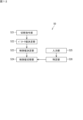
- FIG. 1 is a diagram illustrating an example of the configuration of a winding switching system according to the first embodiment.
- FIG. 2 is a circuit diagram showing an example of the configuration of the winding switching device according to the first embodiment.
- FIG. 3 is a circuit diagram showing an example of the configuration of the control circuit.
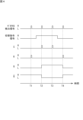
- FIG. 4 is a timing chart showing an example of transition of the states of the signals in the winding switching device according to the first embodiment.
- FIG. 5 is a block diagram illustrating an example of a hardware configuration of the control device according to the first embodiment.
- FIG. 6 is a functional block diagram illustrating an example of functions of the control device according to the first embodiment.
- FIG. 7 is a control block diagram showing a motor control system of the control device according to the first embodiment.
- FIG. 1 is a diagram illustrating an example of the configuration of a winding switching system according to the first embodiment.
- FIG. 2 is a circuit diagram showing an example of the configuration of the winding switching device according to the first embodiment.
- FIG. 3
- FIG. 8 is a graph showing an example of a change in the control voltage value.
- FIG. 9 is a flowchart showing an example of a motor control process performed by the control device according to the first embodiment.
- FIG. 10 is a circuit diagram showing an example of the configuration of a winding switching device according to the second embodiment.
- FIG. 11 is a circuit diagram showing an example of the configuration of a winding switching device according to the third embodiment.
- FIG. 12 is a functional block diagram illustrating an example of functions of the control device according to the third embodiment.
- FIG. 13 is a flowchart showing an example of a motor control process performed by the control device according to the third embodiment.
- the control device is a control device for controlling an AC motor capable of switching the connection state of multiple windings from a first connection state to a second connection state, and includes a switching command unit that commands a winding switching device that switches the connection state of the multiple windings to execute zero-cross switching, which switches the connection state of the multiple windings from the first connection state to the second connection state at a zero-cross point of a current flowing through the windings, and a control value switching unit that switches a control value for controlling the AC motor from a first control value used in the first connection state to a second control value used in the second connection state when the zero-cross switching is executed, and the control value switching unit gradually changes the control value from the first control value to the second control value.
- the AC motor may be a multi-phase AC motor
- the control value switching unit may synchronize the change of each of the control values corresponding to each phase from the first control value to the second control value. This allows the control value of each phase to be gradually changed from the first control value to the second control value at the same timing.
- the AC motor may be an n-phase AC motor (n is an integer equal to or greater than 3), and the control value switching unit may complete the change of each of the n control values from the first control value to the second control value after ⁇ (n-1)/n has elapsed since the start of the change, where ⁇ is the wavelength of the current supplied to the AC motor. This allows the control value of each phase to be gradually changed from the first control value to the second control value during a period that matches the phase difference of the n-phase AC current.
- the control value switching unit may start changing each of the n control values from the first control value to the second control value at a zero cross point of a current of a first phase of the n-phase AC. This allows the control value of each phase to be gradually changed from the first control value to the second control value during the period from the zero cross point of the first phase to the zero cross point of the nth phase.
- control device may further include a specification unit that specifies n switching timings at which the winding switching device executes the zero-crossing switching in each of the n phases, and the control value switching unit may start changing each of the n control values from the first control value to the second control value at the first switching timing of the n switching timings specified by the specification unit. This allows the control value of each phase to be gradually changed from the first control value to the second control value during the period from the time when the zero-crossing switching is executed in the first phase to the time when the zero-crossing switching is executed in the nth phase.
- the control device may further include a parameter value determination unit that determines a parameter value of a control parameter used to determine the control value, and a control value determination unit that determines the control value based on the parameter value determined by the parameter value determination unit, the control value determination unit determines the first control value and the second control value, and the control value switching unit may simultaneously hold the first control value and the second control value determined by the control value determination unit, and switch the control value from the held first control value to the held second control value. In this way, the control value switching unit can gradually change the control value of each phase based on the simultaneously held first control value and second control value.
- the parameter value determination unit may determine a first parameter value that is a parameter value in the first connection state and a second parameter value that is a parameter value in the second connection state, and the control value determination unit may simultaneously hold the first parameter value and the second parameter value determined by the parameter value determination unit, determine the first control value based on the held first parameter value, and determine the second control value based on the held second parameter value. This allows the control value determination unit to determine each of the first control value and the second control value based on each of the first parameter value and second parameter value held simultaneously.
- control value may be a voltage value of a voltage applied to the winding. This allows the voltage applied to the winding to be gradually changed, and the occurrence of surge voltage and oscillation of current control can be suppressed.
- the winding switching system includes an AC motor capable of switching the connection state of a plurality of windings from a first connection state to a second connection state, a power converter that converts power output from a power source into AC power and supplies the AC power to the AC motor, a winding switching device that performs zero-cross switching to switch the connection state of the plurality of windings from the first connection state to the second connection state at a zero-cross point of a current flowing through the windings, and a control device.
- the control device includes a switching command unit that commands the winding switching device to perform the zero-cross switching, and a control value switching unit that switches a control value for controlling the AC motor from a first control value used in the first connection state to a second control value used in the second connection state when the zero-cross switching is performed, and the control value switching unit gradually changes the control value from the first control value to the second control value. This makes it possible to prevent the control value from changing suddenly from the first control value to the second control value. Therefore, it is possible to suppress the generation of a surge voltage and suppress the transmission of current control of the motor.
- the vehicle includes an AC motor capable of switching the connection state of a plurality of windings from a first connection state to a second connection state, a power converter that converts power output from a power source into AC power and supplies the AC power to the AC motor, a winding switching device that performs zero-cross switching to switch the connection state of the plurality of windings from the first connection state to the second connection state at a zero-cross point of a current flowing through the windings, and a control device.
- the control device includes a switching command unit that commands the winding switching device to perform the zero-cross switching, and a control value switching unit that switches a control value for controlling the AC motor from a first control value used in the first connection state to a second control value used in the second connection state when the zero-cross switching is performed, and the control value switching unit gradually changes the control value from the first control value to the second control value. This makes it possible to prevent the control value from changing suddenly from the first control value to the second control value. Therefore, it is possible to suppress the generation of a surge voltage and suppress the transmission of current control of the motor.
- the control method is a control method for controlling an AC motor capable of switching the connection state of multiple windings from a first connection state to a second connection state, and includes the steps of: instructing a winding switching device that switches the connection state of the multiple windings to execute zero-cross switching, which switches the connection state of the multiple windings from the first connection state to the second connection state at a zero-cross point of a current flowing through the windings; and, when the zero-cross switching is executed, switching a control value for controlling the AC motor from a first control value used for the first connection state to a second control value used for the second connection state, in which the control value is gradually changed from the first control value to the second control value in the step of switching the control value.
- This makes it possible to prevent the control value from changing suddenly from the first control value to the second control value. Therefore, it is possible to suppress the generation of a surge voltage and suppress the transmission of current control of the motor.
- the control program according to this embodiment is a control program for controlling an AC motor capable of switching the connection state of multiple windings from a first connection state to a second connection state, and causes a computer to execute the steps of instructing a winding switching device that switches the connection state of the multiple windings to execute zero-cross switching, which switches the connection state of the multiple windings from the first connection state to the second connection state at a zero-cross point of a current flowing through the windings, and switching a control value for controlling the AC motor from a first control value used for the first connection state to a second control value used for the second connection state when the zero-cross switching is executed, and in the step of switching the control value, the control value is gradually changed from the first control value to the second control value.
- This makes it possible to prevent the control value from changing suddenly from the first control value to the second control value. Therefore, it is possible to suppress the generation of a surge voltage and suppress the transmission of current control of the motor.
- the present disclosure can be realized not only as a control device having the above-mentioned characteristic configuration, a winding switching system including a control device, a vehicle including a control device, a control method having steps corresponding to characteristic processes in the control device, and a control program for causing a computer to execute the characteristic processes, but also as a semiconductor integrated circuit that realizes part or all of the control device.
- FIG. 1 is a diagram illustrating an example of the configuration of a winding switching system according to the first embodiment.
- the winding switching system 10 is mounted on a vehicle (hereinafter referred to as an "electric vehicle") that is propelled by a motor, such as an electric vehicle or a plug-in hybrid vehicle.
- the winding switching system 10 includes a motor 20, a power converter 30, a battery 40, a control device 50, and a winding switching device 100.
- the motor 20 is a driving motor that generates propulsive force for the electric vehicle.
- the motor 20 is driven by three-phase AC power.
- One example of the motor 20 is a permanent magnet synchronous motor.
- a position sensor 26 is provided on the output shaft of the motor 20.
- the position sensor 26 detects the rotation angle of the output shaft of the motor 20.
- the position sensor 26 is, for example, a rotary encoder or a rotary potentiometer.
- the position sensor 26 is connected to the control device 50 by a signal line. The detection signal of the position sensor 26 is output to the control device 50.
- the battery 40 is a battery that supplies power to drive the motor 20.
- the battery 40 is a secondary battery, for example a lithium ion battery.
- the power converter 30 is an inverter that converts DC power supplied from the battery 40 into three-phase AC power.
- the power converter 30 may also have the function of converting the three-phase AC power output when the motor 20 functions as a generator into DC power and charging the battery 40.
- the power converter 30 includes legs for the U, V, and W phases.
- the U-phase leg includes switches 31u and 32u
- the V-phase leg includes switches 31v and 32v
- the W-phase leg includes switches 31w and 32w.
- the switches 31u, 32u, 31v, 32v, 31w, and 32w perform switching to convert DC power into three-phase AC power.
- the switches 31u, 32u, 31v, 32v, 31w, and 32w are, for example, IGBTs (Insulated Gate Bipolar Transistors) or power MOSFETs (Metal Oxide Semiconductor Field-Effect Transistors).
- Power line 35u corresponding to U phase extends from the U phase leg
- power line 35v corresponding to V phase extends from the V phase leg
- power line 35w corresponding to W phase extends from the W phase leg.
- current sensor 33u is provided on power line 35u
- current sensor 33v is provided on power line 35v
- current sensor 33w is provided on power line 35w.
- Current sensor 33u detects the current value of current Iu of U phase.
- Current sensor 33v detects the current value of current Iv of V phase.
- Current sensor 33w detects the current value of current Iw of W phase.
- Current sensors 33u, 33v, 33w can detect the current values of currents Iu, Iv, Iw flowing in power lines 35u, 35v, 35w, including DC and AC components.
- the current sensors 33u, 33v, and 33w are, for example, DCCTs (direct current transformers) or shunt resistors.
- Current sensors 33u, 33v, and 33w are connected to the control device 50 by signal lines. The detection values of current sensors 33u, 33v, and 33w are output to the control device 50.
- the winding switching device 100 is disposed between the motor 20 and the power converter 30. However, the position of the winding switching device 100 is not limited to between the motor 20 and the power converter 30.
- the power converter 30 and the winding switching device 100 are connected by power lines 35u, 35v, and 35w, and the winding switching device 100 and the motor 20 are connected by a plurality of power lines 25.
- the winding switching device 100 switches the connection state of the multiple windings of the motor 20. The configuration of the winding switching device 100 will be described later.
- the three-phase AC current output from the power converter 30 is supplied to the motor 20 via the winding switching device 100.
- the control device 50 controls the power converter 30 and the winding switching device 100. Specifically, signal lines extend from the control device 50 to each of the switches 31u, 32u, 31v, 32v, 31w, and 32w, and the control device 50 controls the on/off timing of the switches 31u, 32u, 31v, 32v, 31w, and 32w. A signal line extends from the control device 50 to the winding switching device 100, and the control device 50 outputs a switching command signal to command the winding switching device 100 to switch the connection state of the windings.
- FIG. 2 is a circuit diagram showing an example of the configuration of the winding switching device according to the first embodiment.
- the motor 20 includes a plurality of windings 21u, 22u, 21v, 22v, 21w, and 22w.
- the windings 21u and 22u correspond to the U phase
- the windings 21v and 22v correspond to the V phase
- the windings 21w and 22w correspond to the W phase.
- the number of windings for each phase is not limited to two, and may be three or more.
- the windings 22u, 22v, and 22w are connected at a neutral point 23.
- the winding switching device 100 switches the connection state of the windings 21u, 22u, 21v, 22v, 21w, and 22w for each phase between a series connection state and a parallel connection state.
- the winding switching device 100 includes current sensors 101u, 101v, and 101w, zero-cross detection circuits 102u, 102v, and 102w, control circuits 103u, 103v, and 103w, and switching circuits 104u, 104v, and 104w.
- the zero-cross detection circuits 102u, 102v, and 102w detect the zero-cross point (the point at which the AC signal output from the current sensors 101u, 101v, and 101w crosses the zero reference voltage) of the measurement value of the current sensors 101u, 101v, and 101w.
- the zero-cross detection circuits 102u, 102v, and 102w compare the output voltage from the current sensors 101u, 101v, and 101w with zero voltage, and detect the point at which the output voltage from the current sensors 101u, 101v, and 101w matches the zero voltage as the zero-cross point.
- the zero voltage is an example of a reference voltage.
- the reference voltage is a voltage corresponding to the output voltage of the current sensors 101u, 101v, and 101w when the current flowing through the windings 21u, 22u, 21v, 22v, 21w, and 22w becomes zero current, and is not limited to zero voltage.
- the zero-cross detection circuits 102u, 102v, and 102w are examples of a detection unit.
- the switching circuits 104u, 104v, and 104w switch the connection state of the windings 21u, 22u, 21v, 22v, 21w, and 22w between a series connection state and a parallel connection state when the zero-cross detection circuits 102u, 102v, and 102w detect a zero-cross point.
- the switching circuits 104u, 104v, and 104w are an example of a switching unit.
- the series connection state is an example of a first connection state
- the parallel connection state is an example of a second connection state.
- Power line 35u is connected to one end of winding 21u.
- Power line 212u extends from the other end of winding 21u.
- Power line 221u extends from one end of winding 22u, and power line 222u extends from the other end.
- the switching circuit 104u includes semiconductor relays 111u, 112u, and 113u.
- the semiconductor relays 111u, 112u, and 113u are, for example, IGBTs or power MOSFETs.
- the power line 35u is drawn into the winding switching device 100. Inside the winding switching device 100, the power line 35u branches at a midpoint and is connected to a first terminal of a semiconductor relay 111u. The second terminal of the semiconductor relay 111u is connected to a first terminal of a semiconductor relay 112u. A power line 221u extending from the winding 22u is connected to the connection point between the second terminal of the semiconductor relay 111u and the first terminal of the semiconductor relay 112u.
- the second terminal of the semiconductor relay 112u is connected to the first terminal of the semiconductor relay 113u.
- a power line 212u extending from the winding 21u is connected to the connection point between the second terminal of the semiconductor relay 112u and the first terminal of the semiconductor relay 113u.
- a power line 222u extending from the winding 22u is connected to the second terminal of the semiconductor relay 113u.
- the windings 21u and 22u are connected in series.
- the semiconductor relays 111u and 113u are in the ON state and the semiconductor relay 112u is in the OFF state, the windings 21u and 22u are connected in parallel.
- a signal line extending from the control circuit 103u is connected to each of the gate terminals of the semiconductor relays 111u, 112u, and 113u.
- the power lines 212u, 221u, and 222u extend from the motor 20 and are drawn into the winding switching device 100.
- a current sensor 101u is attached to the power line 221u.
- the current sensor 101u may be attached to the power lines 35u, 212u, or 222u instead of the power line 221u.
- the current sensor 101u detects the U-phase current flowing through the power line 221u.
- the current sensor 101u is, for example, an ACCT that detects only the AC component of the current.
- the signal line extending from the current sensor 101u is connected to the zero-cross detection circuit 102u.
- a signal line transmitting the output signal of the zero-cross detection circuit 102u (hereinafter referred to as the "zero-cross detection signal") extends from the zero-cross detection circuit 102u to the control circuit 103u.
- a signal line extending from the control device 50 is connected to the control circuit 103u.
- the zero-cross detection circuit 102u detects the zero-cross point of the measurement value by the current sensor 101u of the winding current flowing through the power line 221u.
- the zero-cross detection circuit 102u is a comparator.
- the inverting input of the comparator is set to a zero reference voltage, and the output signal of the current sensor 101u is applied to the non-inverting input.
- the output of the comparator changes from low to high.
- FIG. 3 is a circuit diagram showing an example of the configuration of the control circuit 103u.
- the control circuit 103u includes AND circuits 131 and 133, a NOT circuit 132, and a latch circuit 120.
- a signal line extending from the zero-cross detection circuit 102u is connected to a first input terminal of the AND circuit 131 and a first input terminal of the AND circuit 133.
- a signal line extending from the control device 50 is connected to a second input terminal of the AND circuit 131.
- the signal line from the control device 50 is connected to an input terminal of the NOT circuit 132.
- a signal line extending from the output terminal of the NOT circuit 132 is connected to a second input terminal of the AND circuit 133.
- the latch circuit 120 is an RS flip-flop.
- the output terminal of the AND circuit 131 is connected to the input S (set) of the RS flip-flop 120.
- the output terminal of the AND circuit 133 is connected to the input R (reset) of the RS flip-flop 120.
- the RS flip-flop 120 includes two NOT circuits 121 and 123 and two NAND circuits 122 and 124. However, the RS flip-flop 120 may also be composed of two NOR circuits.
- the output Q of the RS flip-flop 120 is connected to the gates of the semiconductor relays 111u and 113u.
- the output Q bar of the RS flip-flop 120 is connected to the gate of the semiconductor relay 112u.
- the zero-cross switching is an operation for switching the connection states of the windings 21u, 22u, 21v, 22v, 21w, and 22w between a series connection state and a parallel connection state at the zero-cross points of the winding currents Iu, Iv, and Iw. Note that the following description will be given representatively of the switching operation of the connection states of the windings 21u and 22u for the U phase. The same applies to the V and W phases, and therefore the description will be omitted.
- FIG. 4 is a timing chart showing an example of the transition of the states of the signals of the winding switching device 100 according to the first embodiment.
- the current sensor 101u measures the winding current Iu flowing through the power line 221u.
- the zero-cross detection circuit 102u detects the zero-cross points of the measured value of the winding current Iu. That is, the zero-cross detection signal output from the zero-cross detection circuit 102u is low when the winding current Iu is not zero, and becomes high when the winding current Iu becomes zero. In FIG. 4, the zero-cross detection signal is low under normal conditions, and is high at times T1, T2, T3, and T4.
- control device 50 sets the value of the switching command signal to Low, and when windings 21u, 22u, 21v, 22v, 21w, and 22w are connected in parallel, control device 50 sets the value of the switching command signal to High.
- the switching command signal is Low in the initial state and changes to High at a point between times T1 and T2.
- the switching command signal changes again to Low at a point between times T3 and T4.
- the zero-cross detection signal and the switching command signal are input to the AND circuit 131.
- the AND circuit 131 outputs Low when the zero-cross detection signal and the switching command signal are a combination of (Low, Low), (Low, High), and (High, Low).
- the AND circuit 131 outputs High when the zero-cross detection signal and the switching command signal are a combination of (High, High). That is, Low is normally input to S of the RS flip-flop 120, and High is input when a zero-cross point of the winding current Iu is detected and a parallel connection command for the windings 21u, 22u, 21v, 22v, 21w, and 22w is given.
- the input signal to S is High at times T2 and T3.
- the zero-cross detection signal and the inverted signal of the switching command signal are input to the AND circuit 133.
- the AND circuit 133 outputs Low when the zero-cross detection signal and the switching command signal are combinations of (Low, Low), (High, Low), and (High, High).
- the AND circuit 133 outputs High when the zero-cross detection signal and the switching command signal are combinations of (High, Low). That is, Low is normally input to R of the RS flip-flop 120, and High is input when a zero-cross point of the winding current Iu is detected and a series connection command for the windings 21u, 22u, 21v, 22v, 21w, and 22w is given.
- the input signal of R is High at times T1 and T4.
- RS flip-flop 120 holds the previous output values of Q and Q-bar when inputs S and R are Low and Low. When inputs S and R are Low and High, RS flip-flop 120 outputs Q and Q-bar as Low and High, and when inputs S and R are High and Low, Q and Q-bar as High and Low. In RS flip-flop 120, the combination of High and High inputs S and R is prohibited.
- connection state of the windings 21u, 22u, 21v, 22v, 21w, and 22w can be switched between a series connection state and a parallel connection state at the timing of the zero-crossing points of the winding currents Iu, Iv, and Iw. Therefore, the occurrence of surge voltages is suppressed. Furthermore, there is no need for complex processing to identify the period during which the winding currents Iu, Iv, and Iw are below a predetermined value, and the winding switching device 100 can be configured without using a processor such as a CPU, FPGA, or ASIC.
- Hardware configuration of the control device] 5 is a block diagram showing an example of a hardware configuration of the control device according to the first embodiment.
- the control device 50 includes a processor 501, a non-volatile memory 502, a volatile memory 503, and an interface (I/F) 504.
- the volatile memory 503 is, for example, a semiconductor memory such as SRAM (Static Random Access Memory) or DRAM (Dynamic Random Access Memory).
- the non-volatile memory 502 is, for example, a flash memory, a hard disk, or a ROM (Read Only Memory).
- the non-volatile memory 502 stores a motor control program 510, which is a computer program, and data used to execute the motor control program 510. Each function of the control device 50 is achieved by the motor control program 510 being executed by the processor 501.
- the motor control program 510 can be stored in a recording medium such as a flash memory, a ROM, or a CD-ROM.
- the processor 501 controls the power converter 30 and the winding switching device 100 using the motor control program 510.
- the processor 501 is, for example, a CPU (Central Processing Unit). However, the processor 501 is not limited to a CPU.
- the processor 501 may be a GPU (Graphics Processing Unit).
- the processor 501 is, for example, a multi-core processor.
- the processor 501 may be a single-core processor.
- the processor 501 may be, for example, an ASIC (Application Specific Integrated Circuit), or a programmable logic device such as a gate array or an FPGA (Field Programmable Gate Array). In this case, the ASIC or the programmable logic device is configured to be capable of executing the same processing as the motor control program 510.
- ASIC Application Specific Integrated Circuit
- FPGA Field Programmable Gate Array
- the I/F 504 is connected to the winding switching device 100 and the power converter 30.
- the I/F 504 is, for example, an input/output interface or a communication interface.
- the I/F 504 is connected to the current sensors 33u, 33v, and 33w provided in the power converter 30, and can acquire the current value of the U-phase current Iu, the current value of the V-phase current Iv, and the current value of the W-phase current Iw.
- the I/F 504 is connected to each of the switches 31u, 32u, 31v, 32v, 31w, and 32w of the power converter 30, and can control the on/off of the switches 31u, 32u, 31v, 32v, 31w, and 32w.
- the I/F 504 is connected to the control circuits 103u, 103v, and 103w of the winding switching device 100, and can output a switching command signal to the control circuits 103u, 103v, and 103w.
- FIG. 6 is a functional block diagram illustrating an example of functions of the control device according to the first embodiment.
- control device 50 executes the functions of the switching command unit 521, the parameter value determination unit 522, the control value determination unit 523, and the control value switching unit 524.
- the switching command unit 521 commands the winding switching device 100 to execute zero-cross switching.
- the command to execute zero-cross switching is issued by outputting a switching command signal to the control circuits 103u, 103v, and 103w. That is, as described above, when a switching command signal is input to the control circuits 103u, 103v, and 103w, a zero-cross detection signal is output from the zero-cross detection circuits 102u, 102v, and 102w at the time of detection of the next zero-cross point, and zero-cross switching is executed.
- the parameter value determination unit 522 determines the parameter values of the control parameters used to determine the voltages (hereinafter also referred to as "control voltage values") to be applied to the windings 21u, 22u, 21v, 22v, 21w, and 22w. Specifically, the parameter value determination unit 522 determines the parameter values of the control parameters in the following control systems:
- FIG. 7 is a control block diagram showing the motor control system of the control device according to the first embodiment. Below, the determination of the parameter values of the control parameters will be explained using FIG. 7.
- the control device 50 sets a target torque 531 for the motor 20.
- the target torque 531 is calculated, for example, from the target speed of the vehicle.
- the target torque 531 is input to the torque current converter 532.
- the torque current converter 532 converts the target torque 531 into a target current.
- the conversion from the target torque 531 to the target current is performed based on the output characteristics of the motor 20 pre-stored in the control device 50. For example, the output characteristics when the windings 21u, 22u, 21v, 22v, 21w, and 22w are connected in series are different from the output characteristics when the windings 21u, 22u, 21v, 22v, 21w, and 22w are connected in parallel.
- the non-volatile memory 502 of the control device 50 stores two types of output characteristics: the output characteristics when the windings 21u, 22u, 21v, 22v, 21w, and 22w are connected in series, and the output characteristics when the windings 21u, 22u, 21v, 22v, 21w, and 22w are connected in parallel.
- the torque current converter 532 determines the target current according to the output characteristics according to the connection state of the windings 21u, 22u, 21v, 22v, 21w, and 22w at that time.
- the target current obtained by the torque current converter 532 is a current value in the dq coordinate system (hereinafter also referred to as the "dq current value”; the voltage value in the dq coordinate system is also referred to as the “dq voltage value”).
- the detection values of the current sensors 33u, 33v, 33w and the detection value of the position sensor 26 are input to the current converter 533.
- the current converter 533 converts the current values of each phase of the three-phase AC current into dq current values.
- the detection values of the current sensors 33u, 33v, 33w, that is, the dq current values corresponding to the winding currents Iu, Iv, Iw, are output from the current converter 533.
- the difference between the target current output from the torque current conversion unit 532 and the winding current output from the current conversion unit 533 is calculated.
- the calculated difference is input to the F/B control unit 535.
- the F/B control unit 535 calculates the feedback gain based on the difference between the input target current and the winding current. For example, the correspondence between the difference and the feedback gain is determined in advance. For example, two types of correspondence are determined: a correspondence when the windings 21u, 22u, 21v, 22v, 21w, and 22w are connected in series, and a correspondence when the windings 21u, 22u, 21v, 22v, 21w, and 22w are connected in parallel.
- the F/B control unit 535 determines the feedback gain from the difference according to the correspondence according to the connection state of the windings 21u, 22u, 21v, 22v, 21w, and 22w at that time.
- the feedback gain is part of the drive voltage of the motor 20.
- the F/B control unit 535 determines the feedback gain according to a predetermined control method.
- the F/B control unit 535 can determine the feedback gain according to any one of P control (proportional control), PI control (proportional integral control), PD control (proportional differential control), and PID control (proportional integral differential control).
- P control proportional control
- PI control proportional integral control
- PD control proportional differential control
- PID control proportional integral differential control
- the winding current output from the current conversion unit 533 and the detection value of the position sensor 26 are input to the electromotive force calculation unit 536.
- the electromotive force calculation unit 536 calculates control components based on the induced voltage generated in the motor 20, such as non-interference control of the AC current of the motor 20 and mutual inductance between the d and q axes.
- the induced voltage differs when the windings 21u, 22u, 21v, 22v, 21w, and 22w are connected in series and when they are connected in parallel. Therefore, the electromotive force calculation unit 536 calculates the control components based on the induced voltage corresponding to the connection state of the windings 21u, 22u, 21v, 22v, 21w, and 22w at that time.
- Equation (1) The state equation (differential equation) of the permanent magnet synchronous motor in the dq coordinate system is expressed by equation (1).
- ⁇ the motor's rotational angular velocity
- ⁇ a the magnet magnetic flux
- Ra the winding resistance
- Ld and Lq are the winding inductances
- p is the differential symbol.
- the influence of the interference term between the d-axis and q-axis due to the induced electromotive force is eliminated.
- the d-axis and q-axis voltages are corrected as shown in the following equation (2).
- vod is the d-axis component of the induced electromotive force
- voq is the q-axis component of the induced electromotive force.
- the feedback gain output from the F/B control unit 535 and the control component output from the electromotive force calculation unit 536 are input to the summing point 537.
- the summing point 537 adds the feedback gain output from the F/B control unit 535 and the control component output from the electromotive force calculation unit 536 to calculate a control voltage value.
- the control voltage value is an example of a "control value”.
- the control voltage value is input to the voltage conversion unit 538.
- the voltage conversion unit 538 converts the dq voltage value into a three-phase AC voltage.
- the control voltage value of the three-phase AC voltage output from the voltage conversion unit 538 is input to the PWM unit 539.
- the PWM unit 539 determines a duty ratio according to the input control voltage value, and generates PWM signals for driving each of the switches 31u, 32u, 31v, 32v, 31w, and 32w of the power converter 30 according to the determined duty ratio.
- the PWM unit 539 outputs the generated PWM signals to each of the switches 31u, 32u, 31v, 32v, 31w, and 32w.
- control parameters include a target current, a feedback gain, and a control component based on the induced voltage.
- the parameter value determination unit 522 can determine each of the target current in the series connection state of the windings 21u, 22u, 21v, 22v, 21w, and 22w, the target current in the parallel connection state, the feedback gain in the series connection state, the feedback gain in the parallel connection state, the control component based on the induced voltage in the series connection state, and the control component based on the induced voltage in the parallel connection state.
- the parameter value determination unit 522 determines each of the target current in the series connection state, the feedback gain in the series connection state, and the control component based on the induced voltage in the series connection state.
- the parameter value determination unit 522 determines the target current in the parallel connection state, the feedback gain in the parallel connection state, and the control component based on the induced voltage in the parallel connection state.
- the control value determination unit 523 determines the control voltage value. Specifically, the control value determination unit 523 can add the feedback gain determined by the parameter value determination unit 522 to a control component based on the induced voltage to calculate the control voltage value. The control value determination unit 523 determines the control voltage value in the series connection state of the windings 21u, 22u, 21v, 22v, 21w, and 22w, and the control voltage value in the parallel connection state of the windings 21u, 22u, 21v, 22v, 21w, and 22w.
- control value determination unit 523 adds the feedback gain in the series connection state of the windings 21u, 22u, 21v, 22v, 21w, and 22w to the control component based on the induced voltage in the series connection state to calculate the control voltage value in the series connection state.
- the control value determination unit 523 adds the feedback gain in the parallel connection state of the windings 21u, 22u, 21v, 22v, 21w, and 22w and the control component based on the induced voltage in the parallel connection state to calculate the control voltage value in the parallel connection state.
- the parameter value determination unit 522 may determine, in the same control cycle, the target current, feedback gain, and control components based on the induced voltage when the windings 21u, 22u, 21v, 22v, 21w, and 22w are connected in series, and the target current, feedback gain, and control components based on the induced voltage when the windings 21u, 22u, 21v, 22v, 21w, and 22w are connected in parallel.
- the control cycle is the control sequence in the above-mentioned control system, from when the PWM duty ratio is determined and a PWM signal is output, until the next duty ratio is determined and the next PWM signal is output.
- the parameter value determination unit 522 can determine, in the same control cycle, each of the control components based on the target current, feedback gain, and induced voltage in the series connection state of the windings 21u, 22u, 21v, 22v, 21w, and 22w, and each of the control components based on the target current, feedback gain, and induced voltage in the parallel connection state of the windings 21u, 22u, 21v, 22v, 21w, and 22w.
- the control device 50 decides to perform zero-cross switching in response to the gear shift instruction.
- the control device 50 can determine that zero-cross switching will be performed soon.
- the parameter value determination unit 522 when the parameter value determination unit 522 outputs a switching command signal to the winding switching device 100, the parameter value determination unit 522 can determine, in the same control cycle, the target current, feedback gain, and control components based on the induced voltage in the series connection state of the windings 21u, 22u, 21v, 22v, 21w, and 22w, and the target current, feedback gain, and control components based on the induced voltage in the parallel connection state of the windings 21u, 22u, 21v, 22v, 21w, and 22w.
- the parameter value determination unit 522 can determine only the target current, feedback gain, and control components based on the induced voltage in the connection state (series connection state or parallel connection state) of the windings 21u, 22u, 21v, 22v, 21w, 22w21u, 22uIu, Iv, and Iw at that time.
- control value determination unit 523 can simultaneously hold each of the control components based on the feedback gain and induced voltage in the series connection state of the windings 21u, 22u, 21v, 22v, 21w, and 22w determined by the parameter value determination unit 522, and each of the control components based on the feedback gain and induced voltage in the parallel connection state of the windings 21u, 22u, 21v, 22v, 21w, and 22w.
- control value determination unit 523 can hold each of the control components based on the feedback gain and induced voltage in the series connection state of the windings 21u, 22u, 21v, 22v, 21w, and 22w determined by the parameter value determination unit 522, and each of the control components based on the feedback gain and induced voltage in the parallel connection state of the windings 21u, 22u, 21v, 22v, 21w, and 22w, in the same control cycle (the control cycle in which these parameter values are determined).
- the control value determination unit 523 can determine the control voltage value in the series state by adding up the control components based on the feedback gain and induced voltage in the held series state, and can also determine the control voltage value in the parallel state by adding up the control components based on the feedback gain and induced voltage in the held parallel state. That is, the control value determination unit 523 can determine the control voltage value in the series state and the control voltage value in the parallel connection state in the same control cycle.
- the control value determination unit 523 can determine, in the same control cycle, the control voltage value in the series connection state of the windings 21u, 22u, 21v, 22v, 21w, and 22w, and the control voltage value in the parallel connection state of the windings 21u, 22u, 21v, 22v, 21w, and 22w.
- control value determination unit 523 can only determine the control voltage value in the connection state (series connection state or parallel connection state) of the windings 21u, 22u, 21v, 22v, 21w, 22w21u, 22uIu, Iv, Iw at that time.
- the control value switching unit 524 switches the control voltage value between the control voltage value used in the series connection state (in the series connection state) and the control voltage value used in the parallel connection state (in the parallel connection state). Specifically, when the series connection state is switched to the parallel connection state by zero-cross switching, the control value switching unit 524 switches the control voltage value from the control voltage value in the series connection state to the control voltage value in the parallel connection state. When the parallel connection state is switched to the series connection state by zero-cross switching, the control value switching unit 524 switches the control voltage value from the control voltage value in the parallel connection state to the control voltage value in the series connection state.
- the control voltage value in the connection state before switching is referred to as the "first control voltage value”
- the control voltage value in the connection state after switching is referred to as the "second control voltage value”.
- the control value switching unit 524 gradually changes the control voltage value from the first control voltage value to the second control voltage value.
- the control value switching unit 524 changes the control voltage value from the first control voltage value to the second control voltage value in a ramp-like manner over time.
- Figure 8 is a graph showing an example of changes in the control voltage value.
- the vertical axis represents the voltage value (effective value) of the U phase
- the horizontal axis represents time. The same is true for the V phase and W phase.
- a PWM signal for applying the first control voltage value V1 to the windings 21u and 22u is output.
- the control value switching unit 524 changes the control voltage value from the first control voltage value V to the second control voltage value V2 in a ramp-like manner during the period from time T11 to time T12 (hereinafter also referred to as the "switching period"). That is, during the switching period, the control voltage value takes a value between the first control voltage value V1 and the second control voltage value V2. In the example of FIG. 8, the second control voltage value V2 is higher than the first control voltage value V1. Therefore, during the switching period, the control voltage value gradually increases from the first control voltage value to the second control voltage value. By changing the control voltage value in this manner, it is possible to suppress the generation of a surge voltage due to switching of the control voltage value and to suppress oscillation of the current control.
- control voltage value is not limited to a ramp shape.
- control voltage value may change in a curved manner.
- step changing the control voltage value includes changing the control voltage value in steps.
- step changing the control voltage value is not limited to smoothly changing the control voltage value over time.
- the control voltage value may be changed in multiple steps or discretely.
- control value switching unit 524 synchronizes the changes of the U-phase control voltage value, the V-phase control voltage value, and the W-phase control voltage value from the first control voltage value to the second control voltage value.
- synchronization means that the changes of the U-phase control voltage value, the V-phase control voltage value, and the W-phase control voltage value start at the same timing, and the changes of the U-phase control voltage value, the V-phase control voltage value, and the W-phase control voltage value are completed at the same timing.
- the U-phase control voltage value, the V-phase control voltage value, and the W-phase control voltage value each start changing from the first control voltage value at the same timing (the start of the switching period) and reach the second control voltage value at the same timing (the end of the switching period).
- the control value switching unit 524 completes the change of each of the n control voltage values from the first control voltage value to the second control voltage value after ⁇ (n-1)/n has elapsed since the start of the change.
- ⁇ is the period of the winding current.
- n 3.
- the phase of the V-phase current is shifted 2 ⁇ /3 from the phase of the U-phase current
- the phase of the W-phase current is shifted 4 ⁇ /3 from the phase of the U-phase current.
- the point of the V-phase current corresponding to a point on the waveform of the U-phase current is a point ⁇ /3 later than the point on the waveform of the U-phase current
- the point of the W-phase current corresponding to a point on the waveform of the U-phase current is a point 2 ⁇ /3 later than the point on the waveform of the U-phase current. Therefore, by changing the control voltage values of the U-phase, V-phase, and W-phase as described above, the switching period can be adapted to the phase difference of the winding currents Iu, Iv, and Iw.
- control value switching unit 524 starts changing each of the n control voltage values from the first control voltage value to the second control voltage value at the zero cross point of the U-phase current. This allows the change in the control voltage value of each phase to start at the zero cross point of the U-phase current, and the change in the control voltage value of each phase to be completed at the zero cross point of the W-phase current.
- control value switching unit 524 simultaneously holds the first control voltage value and the second control voltage value determined by the control value determination unit 523.
- the control value switching unit 524 switches the control voltage value from the held first control voltage value to the held second control voltage value.
- the control value switching unit 524 can determine how to change the control voltage value from the first control voltage value to the second control voltage value.
- control device 50 executes a motor control process by the processor 501 executing a motor control program 510.
- FIG. 9 is a flowchart showing an example of motor control processing by the control device according to the first embodiment.
- the processor 501 decides to execute zero-cross switching.
- the processor 501 determines whether or not it has been decided to execute zero-cross switching (step S101).
- the processor 501 acquires the detection values output from the current sensors 33u, 33v, and 33w and the detection value output from the position sensor 26 (step S102). The processor 501 calculates the rotation speed of the motor 20 based on the detection value from the position sensor 26.
- the processor 501 determines the parameter values of the control parameters according to the connection states of the windings 21u, 22u, 21v, 22v, 21w, 22w21u, 22uIu, Iv, Iw at that time based on the current values of the acquired winding currents Iu, Iv, Iw and the rotation speed of the motor 20 (step S103).
- the control parameters include a target current, a feedback gain, and a control component based on the induced voltage.
- the processor 501 determines the control voltage value according to the connection state of the windings 21u, 22u, 21v, 22v, 21w, 22w, 21u, 22uIu, Iv, and Iw at that time based on the determined parameter values (step S104).
- the processor 501 determines the duty ratio based on the determined control voltage value, and outputs a PWM signal with the determined duty ratio (step S105).
- the switches 31u, 32u, 31v, 32v, 31w, and 32w are driven in accordance with the PWM signal, and the winding currents Iu, Iv, and Iw are supplied to the motor 20.
- the processor 501 returns to step S101.
- step S101 If it has been determined that zero-cross switching should be performed (YES in step S101), the processor 501 outputs a switching command signal to the winding switching device 100 (step S106). Next, the processor 501 acquires the detection values output from the current sensors 33u, 33v, and 33w and the detection value output from the position sensor 26 (step S107). The processor 501 calculates the rotation speed of the motor 20 based on the detection values from the position sensor 26.
- the processor 501 determines the parameter values corresponding to the series state and the parallel state of the windings 21u, 22u, 21v, 22v, 21w, 22w21u, 22uIu, Iv, Iw based on the current values of the acquired winding currents Iu, Iv, Iw and the rotation speed of the motor 20 (step S108). That is, the processor 501 determines the target currents in each of the series connection state and the parallel connection state, the feedback gains for each of the series connection state and the parallel connection state, and the control components based on the induced voltages in each of the series connection state and the parallel connection state.
- the processor 501 determines the control voltage value in the series connection state and the control voltage value in the parallel connection state based on the determined parameter values (step S109).
- the processor 501 changes the control voltage value used to generate the PWM signal by a predetermined amount (step S110). That is, when the series connection state is switched to the parallel connection state by zero-cross switching, the processor 501 increases (or decreases) the control voltage value by a predetermined amount in order to switch from the control voltage value in the series connection state (first control voltage value) to the control voltage value in the parallel connection state (second control voltage value). When the parallel connection state is switched to the series connection state by zero-cross switching, the processor 501 increases (or decreases) the control voltage value by a predetermined amount in order to switch from the control voltage value in the parallel connection state (first control voltage value) to the control voltage value in the series connection state (second control voltage value).
- the processor 501 determines the duty ratio based on the control voltage value after the predetermined change, and outputs a PWM signal with the determined duty ratio (step S111). Switches 31u, 32u, 31v, 32v, 31w, and 32w are driven in accordance with the PWM signal, and winding currents Iu, Iv, and Iw are supplied to the motor 20.
- the processor 501 determines whether the control voltage value has reached the second control voltage value (step S112). If the control voltage value has not reached the second control voltage value (NO in step S112), the processor 501 returns to step S110. By repeating steps S110 to S112, the control voltage value gradually changes from the first control voltage value to the second control voltage value.
- step S112 If the control voltage value reaches the second control voltage value (YES in step S112), the switching of the control voltage value from the first control voltage value to the second control voltage value is completed. In this case, the processor 501 returns to step S101.
- the winding switching device of the second embodiment switches the connection state of the multiple windings of a motor between a full connection state in which all of the multiple windings are connected, and a partial connection state in which some of the multiple windings are connected.
- FIG. 10 is a circuit diagram showing an example of the configuration of a winding switching device according to the second embodiment.
- Motor 20A includes a plurality of windings 24u, 25u, 24v, 25v, 24w, and 25w. Windings 24u and 25u correspond to the U phase, windings 24v and 25v correspond to the V phase, and windings 24w and 25w correspond to the W phase. However, the number of windings for each phase is not limited to two, and may be three or more.
- the winding switching device 100A switches the connection state of the windings 24u, 25u, 24v, 25v, 24w, and 25w for each phase between a fully connected state and a partially connected state.
- the winding switching device 100A includes current sensors 131u, 131v, and 131w, zero-cross detection circuits 102u, 102v, and 102w, control circuits 103u, 103v, and 103w, and switching circuits 140u, 140v, and 140w.
- the zero-cross detection circuits 102u, 102v, and 102w detect the zero-cross points of the measured values of the current sensors 131u, 131v, and 131w.
- the configuration of the zero-cross detection circuits 102u, 102v, and 102w is the same as that of the first embodiment, so a description thereof will be omitted.
- the switching circuits 140u, 140v, and 140w switch the connection state of the windings 24u, 25u, 24v, 25v, 24w, and 25w between a full connection state and a partial connection state when the zero-cross detection circuits 102u, 102v, and 102w detect a zero-cross point.
- the switching circuits 140u, 140v, and 140w are an example of a switching unit.
- the full connection state is an example of a first connection state
- the partial connection state is an example of a second connection state.
- Power line 35u is connected to one end of winding 24u.
- the other end of winding 24u and one end of winding 25u are connected to each other, and power line 241u extends from the midpoint between winding 24u and winding 25u.
- Power line 241u branches into power lines 242u and 243w.
- Power line 251u extends from the other end of winding 25u.
- Power line 251u branches into power lines 252u and 253w.
- Power line 35v is connected to one end of winding 24v.
- the other end of winding 24v and one end of winding 25v are connected to each other, and power line 241v extends from the midpoint between winding 24v and winding 25v.
- Power line 241v branches into power lines 242v and 243u.
- Power line 251v extends from the other end of winding 25v.
- Power line 251v branches into power lines 252v and 253u.
- Power line 35w is connected to one end of winding 24w.
- the other end of winding 24w and one end of winding 25w are connected to each other, and power line 241w extends from the midpoint between winding 24w and winding 25w.
- Power line 241w branches into power lines 242w and 243v.
- Power line 251w extends from the other end of winding 25w.
- Power line 251w branches into power lines 252w and 253v.
- the switching circuit 140u includes semiconductor relays 141u and 142u.
- the switching circuit 140v includes semiconductor relays 141v and 142v.
- the switching circuit 140w includes semiconductor relays 141w and 142w.
- the semiconductor relays 141u, 142u, 141v, 142v, 141w, and 142w are, for example, IGBTs or power MOSFETs.
- the first terminal of the semiconductor relay 141u is connected to the power line 242u, and the second terminal is connected to the power line 243u.
- the first terminal of the semiconductor relay 142u is connected to the power line 252u, and the second terminal is connected to the power line 253u.
- the connection relationship between the switching circuits 140v and 140w is the same as that of the switching circuit 140u, so a description is omitted.
- the power line 35u is drawn into the winding switching device 100.
- a current sensor 131u is attached to the power line 35u.
- the current sensor 131u detects the U-phase current flowing through the power line 35u.
- the current sensor 131u is, for example, an ACCT that detects only the AC component of the current.
- a signal line extending from the current sensor 131u is connected to the zero-cross detection circuit 102u. The same applies to the V-phase and W-phase.
- the output Q of the RS flip-flop 120 in the control circuit 103u is connected to the gate of the semiconductor relay 141u.
- the output Q bar of the RS flip-flop 120 is connected to the gate of the semiconductor relay 142u. The same is true for the V phase and the W phase.
- winding switching device 100A according to the second embodiment are similar to those of the winding switching device 100 according to the first embodiment, so the same components are given the same reference numerals and their description is omitted.
- control device 50 sets the value of the switching command signal to Low when the windings 24u, 25u, 24v, 25v, 24w, and 25w of the motor 20 are to be fully connected, and sets the value of the switching command signal to High when the windings 24u, 25u, 24v, 25v, 24w, and 25w are to be partially connected.
- connection state of windings 21u, 22u, 21v, 22v, 21w, and 22w can be switched between a fully connected state and a partially connected state at the timing of the zero-crossing points of winding currents Iu, Iv, and Iw.
- the configuration and operation of the power converter 30 and control device 50 according to the second embodiment are similar to those of the power converter 30 and control device 50 according to the first embodiment, and therefore will not be described.
- [3. Third embodiment] 11 is a circuit diagram showing an example of the configuration of a winding switching device according to the third embodiment.
- a signal indicating the timing for switching the connection states of the windings 21u, 22u, 21v, 22v, 21w, and 22w (hereinafter also referred to as a “switching timing signal”) is input to a control device 50.
- the signal output from the output Q of the RS flip-flop 120 is a signal (switching timing signal) indicating the switching timing of the connection state of the windings 21u and 22u.
- the signal line extending from the control circuit 103u to the gate terminal of the semiconductor relay 111u branches at the midpoint, and the branched end is connected to the control device 50.
- the U-phase switching timing signal is input to the control device 50 through this signal line.
- the signal line extending from the control circuit 103v to the gate terminal of the semiconductor relay 111v branches at the midpoint, and the branched end is connected to the control device 50.
- the V-phase switching timing signal is input to the control device 50 through this signal line.
- the W-phase switching timing signal is input to the control device 50 through this signal line. Specifically, the switching timing signal is input to the I/F 504 of the control device 50.
- FIG. 12 is a functional block diagram showing an example of the functions of a control device according to the third embodiment.
- the control device 50 executes the functions of the switching command unit 521, the parameter value determination unit 522, the control value determination unit 523, the control value switching unit 524, as well as the input unit 525 and the identification unit 526.
- the input unit 525 receives a switching timing signal that is output when the winding switching device 100 executes zero-cross switching. That is, the input unit 525 receives a switching timing signal that is output from each of the control circuits 103u, 103v, and 103w of the winding switching device 100 to the gate terminals of the semiconductor relays 111u, 111v, and 111w.
- the determination unit 526 determines the switching timing at which a zero-crossing switch is performed to switch the connection state of the windings 21u, 22u, 21v, 22v, 21w, and 22w from a series connection state to a parallel connection state, or from a parallel connection state to a series connection state, at the zero-crossing points of the winding currents Iu, Iv, and Iw.
- the determination unit 526 determines the switching timing based on the input of a switching timing signal at the input unit 525. For example, the determination unit 526 can determine the switching timing in the U phase, the switching timing in the V phase, and the switching timing in the W phase.
- the control value switching unit 524 starts changing each of the n control voltage values from the first control voltage value to the second control voltage value based on the switching timing identified by the identification unit 526.
- the control value switching unit 524 starts changing each of the control voltage value of the U phase, the control voltage value of the V phase, and the control voltage value of the W phase from the first control voltage value to the second control voltage value at the first switching timing of the three switching timings identified by the identification unit 526.
- the control value switching unit 524 starts changing each of the control voltage value of the U phase, the control voltage value of the V phase, and the control voltage value of the W phase from the first control voltage value to the second control voltage value at the switching timing of the U phase.
- the switching period can be set to 2 ⁇ /3.
- FIG. 13 is a flowchart showing an example of motor control processing by the control device according to the third embodiment.
- Steps S101 to S109 are the same as steps S101 to S109 in the first embodiment.
- a switching timing signal is output from the winding switching device 100 to the control device 50.
- the processor 501 determines the switching timing based on the switching timing signal.
- the processor 501 determines whether or not the switching timing has arrived (step S201). If the switching timing has not arrived (NO in step S201), the processor 501 executes step S201 again.
- Step S110 When the switching timing arrives (YES in step S201), the processor 501 changes the control voltage value used to generate the PWM signal by a predetermined amount (step S110).
- Steps S110 to S112 are the same as steps S110 to S112 in the first embodiment. This makes it possible to start a gradual change in the control voltage value at the timing when the zero-cross switching is executed.
- the determination unit 526 of the control device 50 detects zero crossing points of the winding currents Iu, Iv, Iw, and estimates the switching timing based on the detected zero crossing points. For example, the determination unit 526 can determine the waveforms of the winding currents Iu, Iv, Iw from the time-series detection values of the current sensors 33u, 33v, 33w, and detect the zero crossing points in each of the U-phase, V-phase, and W-phase.
- the determination unit 526 can estimate that the next zero cross point after the switching command signal is input to the winding switching device 100 is the switching timing. For example, the determination unit 526 can estimate the switching timing for each of the U phase, V phase, and W phase.
- the input unit 525 receives the detection values of the current sensors 33u, 33v, and 33w instead of the switching timing signal from the winding switching device 100.
- the determination unit 526 detects the zero-crossing points of the winding currents Iu, Iv, and Iw based on the detection values of the current sensors 33u, 33v, and 33w input to the input unit 525.
- control device 50 according to the fourth embodiment are similar to those of the control device 50 according to the third embodiment, and therefore will not be described.
- Other configurations of the winding switching system according to the fourth embodiment are similar to those of the winding switching system 10 according to the first embodiment, and therefore will not be described.
- Winding switching system 20 Motor 21u, 22u, 21v, 22v, 21w, 22w Winding 23 Neutral point 25 Power line 26 Position sensor 30 Power converter 31u, 32u, 31v, 32v, 31w, 32w Switch 33u, 33v, 33w Current sensor 35u, 35v, 35w Power line 40 Battery 50 Control device 501 Processor 502 Non-volatile memory 503 Volatile memory 504 Interface (I/F) 510 Motor control program 521 Switching command unit 522 Parameter value determination unit 523 Control value determination unit 524 Control value switching unit 525 Input unit 526 Identification unit 531 Target torque 532 Torque current conversion unit 533 Current conversion unit 534 Addition point 535 F/B control unit 536 Electromotive force calculation unit 537 Addition point 538 Voltage conversion unit 539 PWM unit 100 Winding switching device 101u, 101v, 101w Current sensor 102u, 102v, 102w Zero cross detection circuit 103u, 103v, 103w Control circuit 104u, 104v, 104w Switching
Landscapes
- Engineering & Computer Science (AREA)
- Power Engineering (AREA)
- Control Of Ac Motors In General (AREA)
Priority Applications (2)
| Application Number | Priority Date | Filing Date | Title |
|---|---|---|---|
| CN202480015181.7A CN120712713A (zh) | 2023-03-03 | 2024-01-26 | 控制装置、绕组切换系统、车辆、控制方法及控制程序 |
| JP2025505119A JPWO2024185337A1 (https=) | 2023-03-03 | 2024-01-26 |
Applications Claiming Priority (2)
| Application Number | Priority Date | Filing Date | Title |
|---|---|---|---|
| JP2023032764 | 2023-03-03 | ||
| JP2023-032764 | 2023-03-03 |
Publications (1)
| Publication Number | Publication Date |
|---|---|
| WO2024185337A1 true WO2024185337A1 (ja) | 2024-09-12 |
Family
ID=92674422
Family Applications (1)
| Application Number | Title | Priority Date | Filing Date |
|---|---|---|---|
| PCT/JP2024/002516 Ceased WO2024185337A1 (ja) | 2023-03-03 | 2024-01-26 | 制御装置、巻線切替システム、車両、制御方法、及び制御プログラム |
Country Status (3)
| Country | Link |
|---|---|
| JP (1) | JPWO2024185337A1 (https=) |
| CN (1) | CN120712713A (https=) |
| WO (1) | WO2024185337A1 (https=) |
Citations (3)
| Publication number | Priority date | Publication date | Assignee | Title |
|---|---|---|---|---|
| JP2016146695A (ja) * | 2015-02-06 | 2016-08-12 | 株式会社安川電機 | 駆動装置及び輸送機械 |
| JP2020043740A (ja) * | 2018-09-13 | 2020-03-19 | マツダ株式会社 | 電動発電機の制御装置 |
| JP2022036727A (ja) * | 2020-08-24 | 2022-03-08 | 株式会社Soken | インバータの制御装置 |
-
2024
- 2024-01-26 WO PCT/JP2024/002516 patent/WO2024185337A1/ja not_active Ceased
- 2024-01-26 JP JP2025505119A patent/JPWO2024185337A1/ja active Pending
- 2024-01-26 CN CN202480015181.7A patent/CN120712713A/zh active Pending
Patent Citations (3)
| Publication number | Priority date | Publication date | Assignee | Title |
|---|---|---|---|---|
| JP2016146695A (ja) * | 2015-02-06 | 2016-08-12 | 株式会社安川電機 | 駆動装置及び輸送機械 |
| JP2020043740A (ja) * | 2018-09-13 | 2020-03-19 | マツダ株式会社 | 電動発電機の制御装置 |
| JP2022036727A (ja) * | 2020-08-24 | 2022-03-08 | 株式会社Soken | インバータの制御装置 |
Also Published As
| Publication number | Publication date |
|---|---|
| CN120712713A (zh) | 2025-09-26 |
| JPWO2024185337A1 (https=) | 2024-09-12 |
Similar Documents
| Publication | Publication Date | Title |
|---|---|---|
| JP5741966B2 (ja) | 交流電動機の制御装置 | |
| US8497645B2 (en) | Control device for electric motor drive device | |
| US20070296371A1 (en) | Position sensorless control apparatus for synchronous motor | |
| WO2009113509A1 (ja) | インバータ装置 | |
| CN109728761B (zh) | 马达驱动控制装置 | |
| JP5534252B2 (ja) | 交流電動機の制御装置 | |
| JP5910583B2 (ja) | 交流電動機の制御装置 | |
| JP5483218B2 (ja) | 交流電動機の制御装置 | |
| JP5621998B2 (ja) | 交流電動機の制御装置 | |
| CN108432120B (zh) | 旋转电机的控制装置 | |
| WO2024185337A1 (ja) | 制御装置、巻線切替システム、車両、制御方法、及び制御プログラム | |
| JP2022142257A (ja) | 交流回転機の制御装置 | |
| US8729847B2 (en) | Methods, systems and apparatus for generating current commands used to control operation of an electric machine | |
| JP7833974B2 (ja) | 交流回転機の制御装置、及び車両用発電電動機装置 | |
| WO2024185274A1 (ja) | 制御装置、巻線切替システム、制御方法、及び制御プログラム | |
| WO2024185335A1 (ja) | 制御装置、巻線切替システム、制御方法、及び制御プログラム | |
| JP2024048986A (ja) | 制御装置 | |
| WO2020105106A1 (ja) | 交流回転電機の制御装置 | |
| JP2004064837A (ja) | モータ駆動制御装置 | |
| TWI896014B (zh) | 馬達控制裝置及馬達控制方法 | |
| JP5910582B2 (ja) | 交流電動機の制御装置 | |
| WO2024185339A1 (ja) | 制御装置、巻線切替システム、車両、制御方法、及び制御プログラム | |
| WO2025243817A1 (ja) | 制御装置、巻線切替システム、制御方法、及び制御プログラム | |
| Sagar et al. | A Novel Position-Sensorless Control Scheme for Permanent Magnet Brushless DC Motor Using Virtual Rotor Position Once in a Cycle | |
| WO2025041419A1 (ja) | モータ制御装置 |
Legal Events
| Date | Code | Title | Description |
|---|---|---|---|
| 121 | Ep: the epo has been informed by wipo that ep was designated in this application |
Ref document number: 24766712 Country of ref document: EP Kind code of ref document: A1 |
|
| ENP | Entry into the national phase |
Ref document number: 2025505119 Country of ref document: JP Kind code of ref document: A |
|
| WWE | Wipo information: entry into national phase |
Ref document number: 2025505119 Country of ref document: JP |
|
| NENP | Non-entry into the national phase |
Ref country code: DE |
|
| 122 | Ep: pct application non-entry in european phase |
Ref document number: 24766712 Country of ref document: EP Kind code of ref document: A1 |