WO2024185131A1 - 量子デバイス及び量子デバイスの製造方法 - Google Patents
量子デバイス及び量子デバイスの製造方法 Download PDFInfo
- Publication number
- WO2024185131A1 WO2024185131A1 PCT/JP2023/009066 JP2023009066W WO2024185131A1 WO 2024185131 A1 WO2024185131 A1 WO 2024185131A1 JP 2023009066 W JP2023009066 W JP 2023009066W WO 2024185131 A1 WO2024185131 A1 WO 2024185131A1
- Authority
- WO
- WIPO (PCT)
- Prior art keywords
- substrate
- quantum
- electrode
- quantum bit
- capacitive coupling
- Prior art date
- Legal status (The legal status is an assumption and is not a legal conclusion. Google has not performed a legal analysis and makes no representation as to the accuracy of the status listed.)
- Ceased
Links
Images


Classifications
-
- H—ELECTRICITY
- H10—SEMICONDUCTOR DEVICES; ELECTRIC SOLID-STATE DEVICES NOT OTHERWISE PROVIDED FOR
- H10D—INORGANIC ELECTRIC SEMICONDUCTOR DEVICES
- H10D48/00—Individual devices not covered by groups H10D1/00 - H10D44/00
- H10D48/383—Quantum effect devices, e.g. of devices using quantum reflection, diffraction or interference effects
-
- H—ELECTRICITY
- H10—SEMICONDUCTOR DEVICES; ELECTRIC SOLID-STATE DEVICES NOT OTHERWISE PROVIDED FOR
- H10N—ELECTRIC SOLID-STATE DEVICES NOT OTHERWISE PROVIDED FOR
- H10N69/00—Integrated devices, or assemblies of multiple devices, comprising at least one superconducting element covered by group H10N60/00
-
- G—PHYSICS
- G06—COMPUTING OR CALCULATING; COUNTING
- G06N—COMPUTING ARRANGEMENTS BASED ON SPECIFIC COMPUTATIONAL MODELS
- G06N10/00—Quantum computing, i.e. information processing based on quantum-mechanical phenomena
-
- G—PHYSICS
- G06—COMPUTING OR CALCULATING; COUNTING
- G06N—COMPUTING ARRANGEMENTS BASED ON SPECIFIC COMPUTATIONAL MODELS
- G06N10/00—Quantum computing, i.e. information processing based on quantum-mechanical phenomena
- G06N10/40—Physical realisations or architectures of quantum processors or components for manipulating qubits, e.g. qubit coupling or qubit control
-
- H—ELECTRICITY
- H10—SEMICONDUCTOR DEVICES; ELECTRIC SOLID-STATE DEVICES NOT OTHERWISE PROVIDED FOR
- H10D—INORGANIC ELECTRIC SEMICONDUCTOR DEVICES
- H10D62/00—Semiconductor bodies, or regions thereof, of devices having potential barriers
- H10D62/10—Shapes, relative sizes or dispositions of the regions of the semiconductor bodies; Shapes of the semiconductor bodies
- H10D62/113—Isolations within a component, i.e. internal isolations
- H10D62/115—Dielectric isolations, e.g. air gaps
-
- H—ELECTRICITY
- H10—SEMICONDUCTOR DEVICES; ELECTRIC SOLID-STATE DEVICES NOT OTHERWISE PROVIDED FOR
- H10D—INORGANIC ELECTRIC SEMICONDUCTOR DEVICES
- H10D80/00—Assemblies of multiple devices comprising at least one device covered by this subclass
- H10D80/20—Assemblies of multiple devices comprising at least one device covered by this subclass the at least one device being covered by groups H10D1/00 - H10D48/00, e.g. assemblies comprising capacitors, power FETs or Schottky diodes
-
- H—ELECTRICITY
- H10—SEMICONDUCTOR DEVICES; ELECTRIC SOLID-STATE DEVICES NOT OTHERWISE PROVIDED FOR
- H10N—ELECTRIC SOLID-STATE DEVICES NOT OTHERWISE PROVIDED FOR
- H10N60/00—Superconducting devices
- H10N60/80—Constructional details
- H10N60/85—Superconducting active materials
- H10N60/855—Ceramic superconductors
-
- H—ELECTRICITY
- H10—SEMICONDUCTOR DEVICES; ELECTRIC SOLID-STATE DEVICES NOT OTHERWISE PROVIDED FOR
- H10W—GENERIC PACKAGES, INTERCONNECTIONS, CONNECTORS OR OTHER CONSTRUCTIONAL DETAILS OF DEVICES COVERED BY CLASS H10
- H10W90/00—Package configurations
- H10W90/20—Configurations of stacked chips
- H10W90/293—Configurations of stacked chips characterised by non-galvanic coupling between the chips, e.g. capacitive coupling
Definitions
- This disclosure relates to quantum devices and methods for manufacturing quantum devices.
- quantum devices that include quantum bits
- studies are being conducted on increasing the number of quantum bits in order to expand the amount of calculations.
- quantum devices that include multiple quantum bit substrates on which quantum bits are formed have been proposed.
- quantum bits In order to increase the number of quantum bits, it is being considered to connect multiple quantum bits by capacitively coupling multiple substrates on which quantum bits are formed using another opposing substrate (capacitively coupled substrate). In addition, quantum devices are required to shield the quantum bits from external electromagnetic waves.
- the objective of this disclosure is to provide a quantum device and a method for manufacturing the quantum device that can connect quantum bits using a capacitively coupled substrate and block external electromagnetic waves from reaching the quantum bits.
- a quantum device includes a first quantum bit substrate, a second quantum bit substrate, and a capacitively coupled substrate, the first quantum bit substrate including a first quantum bit and a first electrode connected to the first quantum bit, the second quantum bit substrate including a second quantum bit and a second electrode connected to the second quantum bit, and the capacitively coupled substrate including a third electrode capacitively coupled to the first electrode and the second electrode, a shielding layer covering the first quantum bit and the second quantum bit, and an insulating film provided between the third electrode and the shielding layer.
- FIG. 1 is a cross-sectional view showing a quantum device according to the first embodiment.
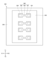
- FIG. 2 is a top view showing the first quantum bit substrate and the second quantum bit substrate in the quantum device according to the first embodiment.
- FIG. 3 is a bottom view showing the capacitive coupling substrate in the quantum device according to the first embodiment.
- FIG. 4 is a cross-sectional view illustrating a method of using the quantum device according to the first embodiment.
- FIG. 5 is a cross-sectional view showing a quantum device according to a reference example.
- FIG. 6 is a cross-sectional view (part 1) showing a first example of a method for manufacturing a capacitive coupling substrate according to the first embodiment.
- FIG. 1 is a cross-sectional view showing a quantum device according to the first embodiment.
- FIG. 2 is a top view showing the first quantum bit substrate and the second quantum bit substrate in the quantum device according to the first embodiment.
- FIG. 3 is a bottom view showing the capacitive coupling substrate in the quantum
- FIG. 7 is a cross-sectional view (part 2) showing a first example of the method for manufacturing the capacitive coupling substrate according to the first embodiment.
- FIG. 8 is a cross-sectional view (part 3) showing a first example of the method for manufacturing the capacitive coupling substrate according to the first embodiment.
- FIG. 9 is a cross-sectional view (part 4) showing a first example of the method for manufacturing the capacitive coupling substrate according to the first embodiment.
- FIG. 10 is a cross-sectional view (part 1) showing a second example of the method for manufacturing the capacitive coupling substrate according to the first embodiment.
- FIG. 11 is a cross-sectional view (part 2) showing a second example of the method for manufacturing the capacitive coupling substrate according to the first embodiment.
- FIG. 12 is a cross-sectional view (part 3) showing a second example of the method for manufacturing the capacitive coupling substrate according to the first embodiment.
- FIG. 13 is a bottom view showing a capacitive coupling substrate in the quantum device according to the second embodiment.
- FIG. 14 is a cross-sectional view showing a quantum device according to the third embodiment.
- FIG. 15 is a cross-sectional view showing a quantum device according to the fourth embodiment.
- FIG. 16 is a cross-sectional view showing a quantum device according to the fifth embodiment.
- FIG. 17 is a cross-sectional view showing a quantum device according to the sixth embodiment.
- FIG. 18 is a top view showing a first quantum bit substrate and a second quantum bit substrate in a quantum device according to the sixth embodiment.
- FIG. 19 is a cross-sectional view showing a quantum device according to the seventh embodiment.
- the X1-X2 direction, the Y1-Y2 direction, and the Z1-Z2 direction are defined as mutually orthogonal directions.
- a plane including the X1-X2 direction and the Y1-Y2 direction is described as the XY plane
- a plane including the Y1-Y2 direction and the Z1-Z2 direction is described as the YZ plane
- a plane including the Z1-Z2 direction and the X1-X2 direction is described as the ZX plane.
- the Z1-Z2 direction is defined as the up-down direction, with the Z1 side as the top and the Z2 side as the bottom.
- a planar view refers to viewing an object from the Z1 side
- a planar shape refers to the shape of an object viewed from the Z1 side.
- quantum devices that include quantum bits and that can perform quantum bit calculations on a larger scale.
- the connection between quantum bits can be achieved by arranging a coupling substrate so as to face multiple quantum bit substrates and providing electrodes on the coupling substrate for coupling between the quantum bits.
- the inventors have further studied a structure that can give the coupling substrate a shielding function that blocks electromagnetic waves from outside.
- Fig. 1 is a cross-sectional view showing a quantum device according to the first embodiment.
- Fig. 2 is a top view showing a first quantum bit substrate and a second quantum bit substrate in the quantum device according to the first embodiment.
- Fig. 3 is a bottom view showing a capacitive coupling substrate in the quantum device according to the first embodiment.
- the quantum device 1 has a first quantum bit substrate 100, a second quantum bit substrate 200, and a capacitive coupling substrate 301. Note that the capacitive coupling substrate 301 is omitted in Figure 2.
- the first quantum bit substrate 100 has a first substrate 110, a plurality of first quantum bits 120, a plurality of first electrodes 130, a plurality of first readout circuits 140, a plurality of first input sections 150, and a plurality of first readout sections 160.
- the first substrate 110 is, for example, a Si substrate, a sapphire substrate, or an MgO substrate.
- the dielectric loss of the first substrate 110 is preferably 1 ⁇ 10 ⁇ 3 or less, more preferably 1 ⁇ 10 ⁇ 4 or less.
- the resistivity of the first substrate 110 is preferably 0.1 k ⁇ cm or more, more preferably 1 k ⁇ cm or more.
- the first substrate 110 has an upper surface 111 on the Z1 side and a lower surface 112 on the Z2 side.
- a plurality of first readout through holes 113 and a plurality of first grounding through holes 114 are formed in the first substrate 110.
- the first quantum bit 120, the first electrode 130, and the first readout circuit 140 are provided on the upper surface 111, and the first input unit 150 is provided on the lower surface 112.
- the first electrode 130 and the first readout circuit 140 are connected to the first quantum bit 120. These connections may be direct or indirect connections by magnetic coupling, capacitive coupling, galvanic coupling, or the like.
- the first input unit 150 and the first quantum bit 120 overlap in a plan view.
- the first readout through hole 113 is formed so that the first readout circuit 140 is located between the first quantum bit 120.
- the first readout unit 160 is provided in the first readout through hole 113, and is indirectly connected to the first readout circuit 140 by magnetic coupling, capacitive coupling, galvanic coupling, or the like.
- the first quantum bit 120 is indirectly connected to adjacent other first quantum bits 120 via inter-bit wiring 181 by magnetic coupling, capacitive coupling, galvanic coupling, or the like.
- a capacitor 182 is provided on the path of the inter-bit wiring 181.
- Each first quantum bit 120 creates a quantum entangled state with the adjacent other first quantum bit 120 to perform quantum operations.
- the first quantum bit 120, the first electrode 130, the first readout circuit 140, the first input section 150, and the first readout section 160 are made of a material that becomes a superconductor at cryogenic temperatures, such as Al, Nb, or TiN.
- a conductor layer 172 that penetrates the first grounding through hole 114 is provided on the lower surface 112, and a conductor layer 171 that is connected to the conductor layer 172 is provided on the upper surface 111.
- the conductor layers 171 and 172 are also made of a material that becomes a superconductor at cryogenic temperatures, such as Al, Nb, TiN, or NbN.
- the conductor layer 171 is an example of a first conductor layer.
- the second quantum bit substrate 200 has a second substrate 210, a plurality of second quantum bits 220, a plurality of second electrodes 230, a plurality of second readout circuits 240, a plurality of second input sections 250, and a plurality of second readout sections 260.
- the second substrate 210 is, for example, a Si substrate, a sapphire substrate, or an MgO substrate.
- the dielectric loss of the second substrate 210 is preferably 1 ⁇ 10 ⁇ 3 or less, more preferably 1 ⁇ 10 ⁇ 4 or less.
- the resistivity of the second substrate 210 is preferably 0.1 k ⁇ cm or more, more preferably 1 k ⁇ cm or more.
- the second substrate 210 has an upper surface 211 on the Z1 side and a lower surface 212 on the Z2 side.
- a plurality of second readout through holes 213 and a plurality of second grounding through holes 214 are formed in the second substrate 210.
- the second quantum bit 220, the second electrode 230, and the second readout circuit 240 are provided on the upper surface 211, and the second input unit 250 is provided on the lower surface 212.
- the second electrode 230 and the second readout circuit 240 are connected to the second quantum bit 220. These connections may be direct or indirect connections by magnetic coupling, capacitive coupling, galvanic coupling, or the like.
- the second input unit 250 and the second quantum bit 220 overlap in a plan view.
- the second readout through hole 213 is formed so that the second readout circuit 240 is located between the second quantum bit 220.
- the second readout unit 260 is provided in the second readout through hole 213, and is indirectly connected to the second readout circuit 240 by magnetic coupling, capacitive coupling, galvanic coupling, or the like.
- the second quantum bit 220 is indirectly connected to another adjacent second quantum bit 220 via inter-bit wiring 281 by magnetic coupling, capacitive coupling, galvanic coupling, or the like.
- a capacitor 282 is provided on the path of the inter-bit wiring 281.
- Each second quantum bit 220 creates a quantum entangled state with the other adjacent second quantum bit 220 to perform quantum operations.
- the second quantum bit 220, the second electrode 230, the second readout circuit 240, the second input section 250, and the second readout section 260 are made of a material that becomes a superconductor at cryogenic temperatures, such as Al, Nb, or TiN.
- a conductor layer 272 that penetrates the second grounding through hole 214 is provided on the lower surface 212, and a conductor layer 271 that is connected to the conductor layer 272 is provided on the upper surface 211.
- the conductor layers 271 and 272 are also made of a material that becomes a superconductor at cryogenic temperatures, such as Al, Nb, TiN, or NbN.
- the conductor layer 271 is an example of a second conductor layer.
- the capacitive coupling substrate 301 has a third substrate 310, a shield layer 320, an insulating film 330, a third electrode 340, and a shield layer 350.
- the third substrate 310 may be a Si substrate with a thermal oxide film. More preferably, the third substrate 310 has a low dielectric loss, for example, a Si substrate, a sapphire substrate, or an MgO substrate.
- the dielectric loss of the third substrate 310 is preferably 1 ⁇ 10 ⁇ 3 or less, more preferably 1 ⁇ 10 ⁇ 4 or less.
- the resistivity of the third substrate 310 is preferably 0.1 k ⁇ cm or more, more preferably 1 k ⁇ cm or more.
- the third substrate 310 has an upper surface 311 on the Z1 side and a lower surface 312 on the Z2 side.
- the shield layer 320 is provided on the lower surface 312, the insulating film 330 is provided on the lower surface of the shield layer 320, and the third electrode 340 and the shield layer 350 are provided on the lower surface of the insulating film 330.
- the insulating film 330 is provided between the shield layer 320 and the third electrode 340 and between the shield layer 350 and the shield layer 320.
- the shield layer 320 covers the first quantum bit 120 and the second quantum bit 220 from the Z1 side.
- the shield layer 320, the third electrode 340, and the shield layer 350 are made of a material that becomes a superconductor at extremely low temperatures, which are the operating temperatures of the first quantum bit 120 and the second quantum bit 220, such as Al, TiN, or NbN.
- the insulating film 330 is made of, for example, an oxide of the material of the shield layer 320, i.e., aluminum oxide, or a nitride, such as aluminum nitride.
- the shield layer 350 is an example of a third conductor layer.
- the third electrode 340 is arranged in an island shape and is electrically insulated from the shield layer 320 and the shield layer 350.
- the potential of the third electrode 340 is, for example, a floating potential.
- the third electrode 340 has a rectangular planar shape, and the dimension (width) of the third electrode 340 in the Y1-Y2 direction is constant. In a planar view, each third electrode 340 overlaps one first electrode 130 and one second electrode 230, and the shield layer 350 overlaps at least partially with the conductor layers 171 and 271.
- the third electrode 340 is capacitively coupled to the first electrode 130 and the second electrode 230.
- the first electrode 130 and the second electrode 230 face the third electrode 340, and the first quantum bit 120 and the second quantum bit 220 face the insulating film 330.
- Quantum device 1 has conductive bonding material 361 that bonds conductor layer 171 and shield layer 350, and conductive bonding material 362 that bonds conductor layer 271 and shield layer 350.
- the material of conductive bonding materials 361 and 362 is, for example, In if it is a superconducting material, and is, for example, Au or Cu if it is a normal conducting material. There may be cases where only superconducting materials are used as conductive bonding materials 361 and 362, cases where only normal conducting materials are used, or cases where both are used.
- the quantum device 1 is used, for example, with a probe substrate attached.
- Figure 4 is a cross-sectional view showing a method of using the quantum device 1 according to the first embodiment.
- the probe substrate 400 has a base material 410, a plurality of first input probes 421, a plurality of second input probes 422, a plurality of first readout probes 431, a plurality of second readout probes 432, a plurality of first ground probes 441, and a plurality of second ground probes 442.
- the first input probes 421, the second input probes 422, the first readout probes 431, the second readout probes 432, the first ground probes 441, and the second ground probes 442 may be fixed to the base material 410.
- first input probes 421, the second input probes 422, the first readout probes 431, and the second readout probes 432 may be coaxial pins, and may have a mechanism for mechanically expanding and contracting the pins.
- Each first input probe 421 contacts one first input unit 150, and each second input probe 422 contacts one second input unit 250.
- Each first read probe 431 contacts one first read section 160, and each second read probe 432 contacts one second read section 260.
- Each first ground probe 441 contacts the conductor layer 172, and each second ground probe 442 contacts the conductor layer 272.
- a ground potential is supplied from the first ground probe 441 and the second ground probe 442 to the conductor layers 171, 172, 271, and 272 and to the shield layer 350.
- a signal for changing the state of the first quantum bit 120 is supplied from the first input probe 421 to the first input section 150, and a signal for changing the state of the second quantum bit 220 is supplied from the second input probe 422 to the second input section 250.
- the state of the first quantum bit 120 is read out from the first readout probe 431, and the state of the second quantum bit 220 is read out from the second readout probe 432.
- Figure 5 is a cross-sectional view showing a quantum device according to the reference example.
- the quantum device 1X of the reference example has a capacitive coupling substrate 301X instead of the capacitive coupling substrate 301.
- the capacitive coupling substrate 301X does not have a shielding layer 320 and an insulating film 330, and a third electrode 340 and a shielding layer 350 are provided on the lower surface 312 of the third substrate 310.
- the other configurations are the same as those of the first embodiment.
- the third electrode 340 is capacitively coupled to the first electrode 130 and the second electrode 230. Therefore, the first electrode 130 and the second electrode 230 are capacitively coupled via the third electrode 340.
- the strength of the capacitive coupling between the first electrode 130 and the second electrode 230 is equal to the strength of the capacitive coupling between adjacent first quantum bits 120 in the first quantum bit substrate 100 and the strength of the capacitive coupling between adjacent second quantum bits 220 in the second quantum bit substrate 200.
- quantum device 1 a shield layer 320 exists above the first quantum bit 120 and the first readout circuit 140, whereas in quantum device 1X, a shield layer 320 does not exist above the first quantum bit 120 and the first readout circuit 140. Therefore, in quantum device 1, a good shielding effect can be obtained against electromagnetic waves from above toward the first quantum bit 120 and the first readout circuit 140, whereas in quantum device 1X, electromagnetic waves from above easily reach the first quantum bit 120 and the first readout circuit 140. Similarly, in quantum device 1, a good shielding effect can be obtained against electromagnetic waves from above toward the second quantum bit 220 and the second readout circuit 240, whereas in quantum device 1X, electromagnetic waves from above easily reach the second quantum bit 220 and the second readout circuit 240.
- the dielectric loss of third substrate 310 is unlikely to affect first quantum bit 120 and first readout circuit 140, but in quantum device 1X, the dielectric loss of third substrate 310 is likely to affect first quantum bit 120 and first readout circuit 140.
- the dielectric loss of third substrate 310 is unlikely to affect second quantum bit 220 and second readout circuit 240, but in quantum device 1X, the dielectric loss of third substrate 310 is likely to affect second quantum bit 220 and second readout circuit 240.
- the space between the first quantum bit substrate 100 and the second quantum bit substrate 200 and the capacitive coupling substrate 301 may be sealed by creating a vacuum or filling this space with an inert gas. In this case, it becomes easier to operate the first quantum bit 120 and the second quantum bit 220 more stably.
- Figures 6 to 9 are cross-sectional views showing a first example of a method for manufacturing the capacitive coupling substrate 301
- Figures 10 to 12 are cross-sectional views showing a second example of a method for manufacturing the capacitive coupling substrate 301.
- a first layer 320A that will become the shield layer 320 is formed on the surface that will become the lower surface 312 of the third substrate 310.
- the first layer 320A can be formed by, for example, a vapor deposition method.
- the first layer 320A is made of, for example, Al or TiN.
- the surface of the first layer 320A is oxidized to form the insulating film 330.
- the remaining portion of the first layer 320A becomes the shield layer 320.
- the insulating film 330 can be formed by, for example, forced oxidation or natural oxidation. Note that, if the first layer 320A is an Al film, this process may be a nitridation process in which the first layer 320A is nitrided.
- a second layer 340A that will become the third electrode 340 and the shield layer 350 is formed on the insulating film 330.
- the second layer 340A can be formed by, for example, a vapor deposition method.
- the second layer 340A is made of, for example, Al or TiN.
- the second layer 340A is processed, for example by etching, to form the third electrode 340 and the shield layer 350. In this manner, the capacitive coupling substrate 301 can be manufactured.
- a resist pattern 380 is formed.
- the resist pattern 380 has openings in the portion where the third electrode 340 is to be formed and the portion where the shield layer 350 is to be formed.
- a third layer 340B that will become the third electrode 340 and the shield layer 350 is formed on the insulating film 330 and the resist pattern 380.
- the third layer 340B can be formed by, for example, a vapor deposition method.
- the third layer 340B is made of, for example, Al or TiN.
- the resist pattern 380 is removed.
- the third layer 340B formed on the resist pattern 380 is also removed.
- the third electrode 340 and the shield layer 350 are formed. In this manner, the capacitive coupling substrate 301 can be manufactured.
- the first quantum bit substrate 100 and the second quantum bit substrate 200 are prepared, and the capacitive coupling substrate 301 is prepared by the method described above. Then, the first quantum bit substrate 100 and the second quantum bit substrate 200 are bonded to the capacitive coupling substrate 301. For this bonding, conductive bonding materials 361 and 362 are used. In this manner, quantum device 1 can be manufactured.
- a second embodiment differs from the first embodiment mainly in the planar shape of the third electrode.
- Fig. 13 is a bottom view showing a capacitive coupling substrate in a quantum device according to the second embodiment.
- the quantum device according to the second embodiment has a capacitive coupling substrate 302 instead of the capacitive coupling substrate 301.
- the third electrode 340 has a first region 341, a second region 342, and a third region 343.
- the first region 341 faces the first electrode 130
- the second region 342 faces the second electrode 230.
- the third region 343 is connected to the first region 341 and the second region 342, and is located between the first region 341 and the second region 342.
- the dimension of the third electrode 340 in the Y1-Y2 direction (second direction) is smaller in the third region 343 than in the first region 341 and the second region 342.
- the Y1-Y2 direction is a direction perpendicular to the X1-X2 direction (first direction) in which the first electrode 130 and the second electrode 230 are aligned in a plan view.
- the second embodiment can also achieve the same effect as the first embodiment. Furthermore, in the second embodiment, the dimension of the third electrode 340 in the Y1-Y2 direction is smaller in the third region 343 than in the first region 341 and the second region 342, making it difficult for magnetic flux quanta to be trapped in the third electrode 340.
- the third embodiment differs from the first embodiment mainly in the configurations of the first quantum bit substrate and the second quantum bit substrate.
- Fig. 14 is a cross-sectional view showing a quantum device according to the third embodiment.
- the first grounding through hole 114 is filled with a conductor layer 172
- the second grounding through hole 214 is filled with a conductor layer 272.
- the third embodiment can achieve the same effect as the first embodiment.
- a fourth embodiment differs from the first embodiment mainly in the configuration of the capacitive coupling substrate.
- Fig. 15 is a cross-sectional view showing a quantum device according to the fourth embodiment.
- the quantum device 4 has a capacitive coupling substrate 304 instead of the capacitive coupling substrate 301.
- the insulating film 330 is formed only between the third electrode 340 and the shield layer 320 and between the shield layer 350 and the shield layer 320, and the insulating film 330 is not formed between the third electrode 340 and the shield layer 350 in a planar view. Therefore, the lower surface of the shield layer 320 is exposed from the insulating film 330.
- the fourth embodiment can achieve the same effects as the first embodiment.
- the fifth embodiment differs from the first embodiment mainly in the configuration of the capacitive coupling substrate.
- Fig. 16 is a cross-sectional view showing a quantum device according to the fifth embodiment.
- the quantum device 5 has a capacitive coupling substrate 305 instead of the capacitive coupling substrate 301.
- the capacitive coupling substrate 305 has a conductive layer 390 formed on the insulating film 330.
- the conductive layer 390 includes a third electrode 340 and a shield layer 350.
- the conductive layer 390 is formed to have a smaller thickness than the third electrode 340 and the shield layer 350 at least in the region facing the first quantum bit 120 and the second quantum bit 220.
- the third electrode 340 and the shield layer 350 are formed by etching the second layer 340A on the insulating film 330.
- the conductive member formed on the insulating film 330 is partially removed by etching to form the third electrode 340 and the shield layer 350, the conductive member on the insulating film 330 is not completely removed and remains between the third electrode 340 and the shield layer 350, forming the conductive layer 390.
- the fifth embodiment can also provide a good shielding effect and suppress the reduction in coherence due to dielectric loss. Furthermore, since the thickness of the conductive layer 390 is thinner in at least the regions of the capacitively coupled substrate 305 that face the first quantum bit 120 and the second quantum bit 220 compared to other regions, the generation of stray capacitance parasitic to the first quantum bit 120 and the second quantum bit 220 can be suppressed.
- the sixth embodiment differs from the first embodiment mainly in the configuration of the first quantum bit substrate and the second quantum bit substrate.
- Fig. 17 is a cross-sectional view showing a quantum device according to the sixth embodiment.
- Fig. 18 is a top view showing the first quantum bit substrate and the second quantum bit substrate in the quantum device according to the sixth embodiment.
- the first quantum bit substrate 100 does not have the first readout through hole 113 and the first grounding through hole 114, and the first quantum bit substrate 100 does not have the conductor layer 172.
- the first input section 150 is provided on the upper surface 111 of the first substrate 110.
- a capacitor 190 is connected between the first quantum bit 120 and the first input section 150.
- the second readout through hole 213 and the second grounding through hole 214 are not formed in the second quantum bit substrate 200, and the first quantum bit substrate 100 does not have the conductor layer 172.
- the second input section 250 is provided on the upper surface 211 of the second substrate 210.
- a capacitor 290 is connected between the second quantum bit 220 and the second input section 250.
- the first input section 150 and the second input section 250 are exposed from the capacitive coupling substrate 301. Bonding wires are connected to the first input section 150 and the second input section 250, respectively.
- signals for changing the states of the first quantum bit 120 and the second quantum bit 220 are input from the bonding wires, rather than from the first input probe 421 and the second input probe 422.
- the sixth embodiment can achieve the same effects as the first embodiment.
- a seventh embodiment differs from the first embodiment mainly in the configuration of the capacitive coupling substrate.
- Fig. 19 is a cross-sectional view showing a quantum device according to the seventh embodiment.
- the quantum device 7 according to the seventh embodiment has a capacitively coupled substrate 307 instead of the capacitively coupled substrate 301.
- the capacitively coupled substrate 307 has a shield layer 351 instead of the shield layer 350.
- the shield layer 351 is thicker than the third electrode 340.
- the shield layer 351 is made of, for example, the same material as the third electrode 340.
- quantum device 7 does not have conductive bonding materials 361 and 362, and shield layer 351 is directly bonded to conductor layers 171 and 271.
- Shield layer 351 is bonded to conductor layers 171 and 271 by, for example, diffusion bonding.
- the seventh embodiment can achieve the same effects as the first embodiment.
- the laminated structure of the shield layer 320 and the insulating film 330 may be repeatedly provided.
- the quantum device may include three or more quantum bit substrates.
- the quantum device disclosed herein can be used, for example, in quantum computing.
- Quantum device 100 First quantum bit substrate 110: First substrate 120: First quantum bit 130: First electrode 200: Second quantum bit substrate 210: Second substrate 220: Second quantum bit 230: Second electrode 301, 302, 304, 305, 307: Capacitively coupled substrate 310: Third substrate 320: Shield layer 330: Insulating film 340: Third electrode 341: First region 342: Second region 343: Third region 350, 351, 370: Shield layer 390: Conductive layer
Landscapes
- Engineering & Computer Science (AREA)
- General Physics & Mathematics (AREA)
- Theoretical Computer Science (AREA)
- Physics & Mathematics (AREA)
- Evolutionary Computation (AREA)
- General Engineering & Computer Science (AREA)
- Condensed Matter Physics & Semiconductors (AREA)
- Data Mining & Analysis (AREA)
- Software Systems (AREA)
- Artificial Intelligence (AREA)
- Mathematical Analysis (AREA)
- Mathematical Optimization (AREA)
- Pure & Applied Mathematics (AREA)
- Computing Systems (AREA)
- Computational Mathematics (AREA)
- Mathematical Physics (AREA)
- Chemical & Material Sciences (AREA)
- Ceramic Engineering (AREA)
- Superconductor Devices And Manufacturing Methods Thereof (AREA)
Priority Applications (4)
| Application Number | Priority Date | Filing Date | Title |
|---|---|---|---|
| JP2025505034A JPWO2024185131A1 (https=) | 2023-03-09 | 2023-03-09 | |
| EP23926341.1A EP4680002A4 (en) | 2023-03-09 | 2023-03-09 | QUANTUM DEVICE AND METHOD FOR MANUFACTURING QUANTUM DEVICES |
| PCT/JP2023/009066 WO2024185131A1 (ja) | 2023-03-09 | 2023-03-09 | 量子デバイス及び量子デバイスの製造方法 |
| US19/318,718 US20260006862A1 (en) | 2023-03-09 | 2025-09-04 | Quantum device and method for manufacturing quantum device |
Applications Claiming Priority (1)
| Application Number | Priority Date | Filing Date | Title |
|---|---|---|---|
| PCT/JP2023/009066 WO2024185131A1 (ja) | 2023-03-09 | 2023-03-09 | 量子デバイス及び量子デバイスの製造方法 |
Related Child Applications (1)
| Application Number | Title | Priority Date | Filing Date |
|---|---|---|---|
| US19/318,718 Continuation US20260006862A1 (en) | 2023-03-09 | 2025-09-04 | Quantum device and method for manufacturing quantum device |
Publications (1)
| Publication Number | Publication Date |
|---|---|
| WO2024185131A1 true WO2024185131A1 (ja) | 2024-09-12 |
Family
ID=92674556
Family Applications (1)
| Application Number | Title | Priority Date | Filing Date |
|---|---|---|---|
| PCT/JP2023/009066 Ceased WO2024185131A1 (ja) | 2023-03-09 | 2023-03-09 | 量子デバイス及び量子デバイスの製造方法 |
Country Status (4)
| Country | Link |
|---|---|
| US (1) | US20260006862A1 (https=) |
| EP (1) | EP4680002A4 (https=) |
| JP (1) | JPWO2024185131A1 (https=) |
| WO (1) | WO2024185131A1 (https=) |
Citations (8)
| Publication number | Priority date | Publication date | Assignee | Title |
|---|---|---|---|---|
| US20100133514A1 (en) * | 2006-12-01 | 2010-06-03 | Bunyk Paul I | Superconducting shielding for use with an integrated circuit for quantum computing |
| US10068181B1 (en) | 2015-04-27 | 2018-09-04 | Rigetti & Co, Inc. | Microwave integrated quantum circuits with cap wafer and methods for making the same |
| US20190207075A1 (en) | 2016-09-14 | 2019-07-04 | Google Llc | Reducing dissipation and frequency noise in quantum devices using a local vacuum cavity |
| US20200287117A1 (en) * | 2019-03-07 | 2020-09-10 | International Business Machines Corporation | Scalable quantum devices with vertical coaxial resonators |
| US20200364600A1 (en) * | 2017-12-29 | 2020-11-19 | Intel Corporation | Quantum computing assemblies |
| JP2021534583A (ja) | 2018-08-13 | 2021-12-09 | オックスフォード ユニヴァーシティ イノヴェーション リミテッド | 超電導量子演算回路パッケージ |
| US20220123048A1 (en) * | 2019-02-15 | 2022-04-21 | D-Wave Systems Inc. | Kinetic inductance for couplers and compact qubits |
| US20220189922A1 (en) | 2020-12-16 | 2022-06-16 | International Business Machines Corporation | Create a protected layer for interconnects and devices in a packaged quantum structure |
Family Cites Families (1)
| Publication number | Priority date | Publication date | Assignee | Title |
|---|---|---|---|---|
| CN110431568B (zh) * | 2017-03-13 | 2024-03-08 | 谷歌有限责任公司 | 在堆叠的量子计算装置中的集成电路元件 |
-
2023
- 2023-03-09 JP JP2025505034A patent/JPWO2024185131A1/ja active Pending
- 2023-03-09 WO PCT/JP2023/009066 patent/WO2024185131A1/ja not_active Ceased
- 2023-03-09 EP EP23926341.1A patent/EP4680002A4/en active Pending
-
2025
- 2025-09-04 US US19/318,718 patent/US20260006862A1/en active Pending
Patent Citations (8)
| Publication number | Priority date | Publication date | Assignee | Title |
|---|---|---|---|---|
| US20100133514A1 (en) * | 2006-12-01 | 2010-06-03 | Bunyk Paul I | Superconducting shielding for use with an integrated circuit for quantum computing |
| US10068181B1 (en) | 2015-04-27 | 2018-09-04 | Rigetti & Co, Inc. | Microwave integrated quantum circuits with cap wafer and methods for making the same |
| US20190207075A1 (en) | 2016-09-14 | 2019-07-04 | Google Llc | Reducing dissipation and frequency noise in quantum devices using a local vacuum cavity |
| US20200364600A1 (en) * | 2017-12-29 | 2020-11-19 | Intel Corporation | Quantum computing assemblies |
| JP2021534583A (ja) | 2018-08-13 | 2021-12-09 | オックスフォード ユニヴァーシティ イノヴェーション リミテッド | 超電導量子演算回路パッケージ |
| US20220123048A1 (en) * | 2019-02-15 | 2022-04-21 | D-Wave Systems Inc. | Kinetic inductance for couplers and compact qubits |
| US20200287117A1 (en) * | 2019-03-07 | 2020-09-10 | International Business Machines Corporation | Scalable quantum devices with vertical coaxial resonators |
| US20220189922A1 (en) | 2020-12-16 | 2022-06-16 | International Business Machines Corporation | Create a protected layer for interconnects and devices in a packaged quantum structure |
Non-Patent Citations (2)
| Title |
|---|
| A. GOLD ET AL., NPJ, vol. 7, 2021, pages 142 |
| See also references of EP4680002A1 |
Also Published As
| Publication number | Publication date |
|---|---|
| JPWO2024185131A1 (https=) | 2024-09-12 |
| US20260006862A1 (en) | 2026-01-01 |
| EP4680002A4 (en) | 2026-04-08 |
| EP4680002A1 (en) | 2026-01-14 |
Similar Documents
| Publication | Publication Date | Title |
|---|---|---|
| US7898073B2 (en) | Semiconductor device and semiconductor module employing thereof | |
| JP7211540B2 (ja) | 配線基板及びその製造方法 | |
| US7842610B2 (en) | Semiconductor device | |
| US11812672B2 (en) | Quantum computing device and system | |
| JP4215495B2 (ja) | 配線構造およびその製造方法ならびに配線構造を備えた半導体装置と配線基板 | |
| KR20040092304A (ko) | 멀티칩 bga 패키지 | |
| JP7290202B2 (ja) | 量子デバイス及び量子計算機 | |
| TW200915937A (en) | Capacitor-embedded substrate and method of manufacturing the same | |
| US12354998B2 (en) | Packaged electronic system formed by electrically connected and galvanically isolated dice | |
| JP6853252B2 (ja) | 半導体素子実装用基板および半導体装置 | |
| TWI287267B (en) | Bonding pad structure of semiconductor device and method for fabricating the same | |
| CN100505178C (zh) | 贯通基板、内插器以及贯通基板的制造方法 | |
| US20230309419A1 (en) | Quantum device | |
| US20220375885A1 (en) | Flip-chip ball grid array-type integrated circuit package for very high frequency operation | |
| WO2024185131A1 (ja) | 量子デバイス及び量子デバイスの製造方法 | |
| US20060145350A1 (en) | High frequency conductors for packages of integrated circuits | |
| US20100244274A1 (en) | Wiring board | |
| JP2024106984A (ja) | キュービットチップ素子及びその製造方法 | |
| US11798895B2 (en) | Quantum device including shield part and method of manufacturing the same | |
| JP2006049557A (ja) | 半導体装置 | |
| JP2024029441A (ja) | 量子デバイス | |
| US20210408358A1 (en) | Quantum device and method of manufacturing the same | |
| JP3839677B2 (ja) | 層間接続ビア構造 | |
| US20260068537A1 (en) | Quantum bit device and method for manufacturing quantum bit device | |
| US20250183508A1 (en) | Transmission line, processing device, and quantum computer |
Legal Events
| Date | Code | Title | Description |
|---|---|---|---|
| 121 | Ep: the epo has been informed by wipo that ep was designated in this application |
Ref document number: 23926341 Country of ref document: EP Kind code of ref document: A1 |
|
| ENP | Entry into the national phase |
Ref document number: 2025505034 Country of ref document: JP Kind code of ref document: A |
|
| WWE | Wipo information: entry into national phase |
Ref document number: 2025505034 Country of ref document: JP |
|
| WWE | Wipo information: entry into national phase |
Ref document number: 2023926341 Country of ref document: EP |
|
| NENP | Non-entry into the national phase |
Ref country code: DE |
|
| ENP | Entry into the national phase |
Ref document number: 2023926341 Country of ref document: EP Effective date: 20251009 |
|
| ENP | Entry into the national phase |
Ref document number: 2023926341 Country of ref document: EP Effective date: 20251009 |
|
| ENP | Entry into the national phase |
Ref document number: 2023926341 Country of ref document: EP Effective date: 20251009 |
|
| ENP | Entry into the national phase |
Ref document number: 2023926341 Country of ref document: EP Effective date: 20251009 |
|
| WWP | Wipo information: published in national office |
Ref document number: 2023926341 Country of ref document: EP |