WO2024181277A1 - 腹水濾過器 - Google Patents
腹水濾過器 Download PDFInfo
- Publication number
- WO2024181277A1 WO2024181277A1 PCT/JP2024/006368 JP2024006368W WO2024181277A1 WO 2024181277 A1 WO2024181277 A1 WO 2024181277A1 JP 2024006368 W JP2024006368 W JP 2024006368W WO 2024181277 A1 WO2024181277 A1 WO 2024181277A1
- Authority
- WO
- WIPO (PCT)
- Prior art keywords
- hollow fiber
- fiber membrane
- port
- treatment liquid
- housing
- Prior art date
- Legal status (The legal status is an assumption and is not a legal conclusion. Google has not performed a legal analysis and makes no representation as to the accuracy of the status listed.)
- Ceased
Links
Images


Classifications
-
- A—HUMAN NECESSITIES
- A61—MEDICAL OR VETERINARY SCIENCE; HYGIENE
- A61M—DEVICES FOR INTRODUCING MEDIA INTO, OR ONTO, THE BODY; DEVICES FOR TRANSDUCING BODY MEDIA OR FOR TAKING MEDIA FROM THE BODY; DEVICES FOR PRODUCING OR ENDING SLEEP OR STUPOR
- A61M1/00—Suction or pumping devices for medical purposes; Devices for carrying-off, for treatment of, or for carrying-over, body-liquids; Drainage systems
-
- B—PERFORMING OPERATIONS; TRANSPORTING
- B01—PHYSICAL OR CHEMICAL PROCESSES OR APPARATUS IN GENERAL
- B01D—SEPARATION
- B01D61/00—Processes of separation using semi-permeable membranes, e.g. dialysis, osmosis or ultrafiltration; Apparatus, accessories or auxiliary operations specially adapted therefor
- B01D61/14—Ultrafiltration; Microfiltration
-
- B—PERFORMING OPERATIONS; TRANSPORTING
- B01—PHYSICAL OR CHEMICAL PROCESSES OR APPARATUS IN GENERAL
- B01D—SEPARATION
- B01D61/00—Processes of separation using semi-permeable membranes, e.g. dialysis, osmosis or ultrafiltration; Apparatus, accessories or auxiliary operations specially adapted therefor
- B01D61/14—Ultrafiltration; Microfiltration
- B01D61/18—Apparatus therefor
-
- B—PERFORMING OPERATIONS; TRANSPORTING
- B01—PHYSICAL OR CHEMICAL PROCESSES OR APPARATUS IN GENERAL
- B01D—SEPARATION
- B01D63/00—Apparatus in general for separation processes using semi-permeable membranes
- B01D63/02—Hollow fibre modules
-
- B—PERFORMING OPERATIONS; TRANSPORTING
- B01—PHYSICAL OR CHEMICAL PROCESSES OR APPARATUS IN GENERAL
- B01D—SEPARATION
- B01D69/00—Semi-permeable membranes for separation processes or apparatus characterised by their form, structure or properties; Manufacturing processes specially adapted therefor
-
- B—PERFORMING OPERATIONS; TRANSPORTING
- B01—PHYSICAL OR CHEMICAL PROCESSES OR APPARATUS IN GENERAL
- B01D—SEPARATION
- B01D71/00—Semi-permeable membranes for separation processes or apparatus characterised by the material; Manufacturing processes specially adapted therefor
- B01D71/06—Organic material
- B01D71/76—Macromolecular material not specifically provided for in a single one of groups B01D71/08 - B01D71/74
Definitions
- This disclosure relates to an ascites filter for treating ascites that occurs due to liver cirrhosis, cancer, etc.
- Ascites contains plasma components that have leaked from the blood, and these plasma components also contain useful proteins such as albumin and globulin.
- CART Cell-free and Concentrated Ascites Reinfusion Therapy
- Patent Documents 1 and 2 disclose an internal pressure type.
- the internal pressure type is a filtration method in which the ascites to be treated is passed from the inside to the outside of the hollow fiber membrane of the ascites filter.
- an external pressure type a filtration method in which the ascites to be treated is passed from the outside to the inside of the hollow fiber membrane.
- the ascites is passed from the outside to the inside of the hollow fiber membrane, and it is expected that by passing through the outer surface, which has a larger area than the inner surface, more impurities will be captured by the more pores (holes formed in the membrane), improving filtration efficiency.
- this is not actually the case.
- the expected improvement in filtration efficiency was not observed even when used with the external pressure type, compared to when used with the internal pressure type.
- the present disclosure therefore aims to provide an ascites filter that can improve cleaning and filtration efficiency.
- the ascites filter according to the first aspect of the present disclosure comprises a housing that is cylindrical with both ends open and has a first port and a second port at positions spaced apart from each other in the axial direction on the peripheral wall, a hollow fiber membrane that is accommodated in the housing and fixed to the housing via a locking portion and is a cylindrical porous membrane, a first header that closes one opening of the housing and has a third port, and a second header that closes the other opening of the housing and has a fourth port, the hollow fiber membrane has a homogenous bamboo grove structure in which the shape and density of the pores within the membrane are uniform at any position in the membrane thickness direction, the surface average pore size is 0.1 ⁇ m or more and 0.9 ⁇ m or less, and the porosity is 30% or more and 80% or less.
- the ascites filter according to the present disclosure when used in an external pressure system, the number of holes on the outer surface of the hollow fiber membrane is reliably greater than the number of holes on the inner surface, improving filtration efficiency. Furthermore, by setting the average surface pore size within the above range, clogging is less likely to occur and it is possible to maintain material permeability. Furthermore, by making the structure homogeneous, large substances that are not desired to pass through the inside of the hollow fiber membrane are less likely to pass through, and the ease of liquid flow does not change inside the hollow fiber membrane in any part, so cleaning efficiency and permeability are high. Furthermore, by setting the porosity within the above range, filtration efficiency can be improved. In addition, by using the external pressure system, cleaning liquid can be passed from the inside to the outside of the hollow fiber membrane at high pressure during recovery processing, so cleaning efficiency can also be improved.
- the ascites filter according to the second aspect of the present disclosure may have a substance permeation pore size of 0.1 ⁇ m or more and 0.2 ⁇ m or less in the first aspect.
- the process of passing the treatment liquid from the outside to the inside of the hollow fiber membrane with the first port as a treatment liquid inlet and the fourth port as a treatment liquid outlet and filtering the treatment liquid may be performed as external pressure filtration
- the process of passing the treatment liquid from the inside to the outside of the hollow fiber membrane with the third port as a treatment liquid inlet and the second port as a treatment liquid outlet and filtering the treatment liquid may be performed as internal pressure filtration
- the amount of treatment liquid filtered per unit membrane area which is the value obtained by dividing the amount of treatment liquid filtered until the pressure difference between the inlet and the outlet reaches 40 kPa by the effective area of the inner surface of the hollow fiber membrane, may satisfy V1>V2 in the case of the external pressure filtration and V2 in the case of the internal pressure filtration.
- the ascites filter according to the fourth aspect of the present disclosure may further satisfy 1.00 ⁇ V1/V2 ⁇ 2.00 in the third aspect.
- the hollow fiber membrane in the first or second aspect, may have an outer surface area that is 1.20 times or more and 1.60 times or less than the inner surface area.
- the filtration efficiency can be improved when performing external pressure filtration compared to internal pressure filtration.
- the ascites filter according to the sixth aspect of the present disclosure may be in the first aspect, in which the filling rate, which is the ratio of the hollow fiber membrane to the internal space of the housing in a cross section perpendicular to the axis of the housing, is 40% or more and 60% or less.
- the filtration efficiency will decrease, but if there are too many hollow fiber membranes in the housing, it will be difficult for the ascites to flow through the housing, and the filtration efficiency will also decrease. Therefore, by setting the packing rate range as described above, it is possible to prevent a decrease in filtration efficiency due to such reasons and achieve efficient filtration.
- the hollow fiber membrane may contain ethylene-vinyl alcohol copolymer (EVA) as a hydrophilizing agent.
- EVA ethylene-vinyl alcohol copolymer
- an ascites filter that can improve cleaning efficiency and filtration efficiency.
- FIG. 1 is a schematic diagram showing the configuration of an ascites filter according to the present disclosure.
- FIG. 2 shows an example of a circuit for measuring the amount of filtrated liquid in external pressure filtration.
- FIG. 3 shows an example of a circuit for measuring the amount of filtrated liquid in internal pressure filtration.
- FIG. 4A is an image of the outer surface of the hollow fiber membrane captured by a scanning electron microscope
- FIG. 4B is an image of the inner surface of the hollow fiber membrane
- FIG. 4C is an image of the cross section of the hollow fiber membrane.
- FIG. 5A is an image taken by a scanning electron microscope of the outer surface of a hollow fiber membrane according to a comparative example
- FIG. 5B is an image taken by a scanning electron microscope of the inner surface of the same hollow fiber membrane.
- the hollow fiber membrane Since the hollow fiber membrane is cylindrical, the area of the outer peripheral surface is larger than that of the inner peripheral surface. Therefore, the number of holes is greater on the outer peripheral surface than on the inner peripheral surface, and it was expected that the filtration efficiency of the external pressure type would be higher than that of the internal pressure type. However, as described above, in the conventional hollow fiber membrane, the filtration efficiency is not improved as much as expected even in the external pressure type. After intensively studying this point, the inventor of the present application found that there is no significant difference in the number of holes formed on the inner peripheral surface and the outer peripheral surface.
- a conventional method for manufacturing hollow fiber membranes for ascites filters is the thermally induced phase separation method, which uses a phase separation method.
- a core material is passed through the spinning solution to create hollow fibers that have no pores, and then the hollow fibers are cooled from the inside to generate crystals, which then form pores.
- the hollow fiber membranes produced by this method are cooled less on the outer surface than on the inner surface, and therefore the density of the crystals generated on the outer surface (the number of crystals per unit area) is smaller than that on the inner surface. It is therefore believed that there is no significant difference in the number of holes formed on the inner and outer surfaces.
- the inventors therefore decided to adopt a hollow fiber membrane for an ascites filter that has a homogenous bamboo thicket structure in which the shape and density of the pores within the membrane are uniform at any position in the membrane thickness direction, has a surface average pore size of 0.1 ⁇ m or more and 0.9 ⁇ m or less, and a porosity of 30% or more and 80% or less.
- the ascites filter according to the present disclosure will be described in detail below with reference to the drawings.
- FIG. 1 is a schematic diagram showing the configuration of an ascites filter according to the present disclosure.
- the ascites filter 1 has a casing 2.
- the casing 2 includes a cylindrical housing 10 with both ends open, a first header 11 closing one opening of the housing 10, and a second header 12 closing the other opening of the housing 10.
- a first port 21 and a second port 22 are provided on the peripheral wall of the housing 10, spaced apart from each other in a direction along the axis A of the housing 10.
- the first port 21 and the second port 22 are tubular and protrude in the same direction perpendicular to the axis A.
- the first header 11 is circular when viewed along the axis A, and has a third port 23 at its center.
- This third port 23 is tubular and is arranged so as to be concentric with the axis A of the housing 10.
- the second header 12 is also circular when viewed along the axis A, and has a fourth port 24 at its center.
- This fourth port 24 is also tubular and is arranged so as to be concentric with the axis A of the housing 10.
- the casing 2 which is made up of the housing 10, first header 11, and second header 12, has an internal space 3 in which a hollow fiber body (hollow fiber bundle) 30 is housed.
- the hollow fiber body 30 is formed by bundling multiple hollow fiber membranes 31, and both ends are fixed by resin locking parts 32. When fixed to the locking parts 32, both ends of each hollow fiber membrane 31 are open so that the inside of the hollow fiber membrane 31 and the space surrounded by the locking parts 32 and the headers can communicate with each other.
- Such hollow fiber body 30 is housed in the internal space 3 and is engaged with the inner wall of the casing 2 by the engaging portion 32, and in this state, the first header 11 and the second header 12 are attached to the housing 10.
- the internal space 3 of the casing 2 is divided into three spaces: one side space sandwiched between the first header 11 and one engaging portion 32, a central space sandwiched between one engaging portion 32 and the other engaging portion 32, and the other side space sandwiched between the other engaging portion 32 and the second header 12.
- the one side space and the central space are liquid-tightly separated by one engaging portion 32, and the other side space and the central space are liquid-tightly separated by the other engaging portion 32.
- the one side space and the other side space are connected via the internal space of the hollow fiber membrane 31.
- the first port 21 and the second port 22 communicate with each other through the outer space of the hollow fiber membrane 31.
- the third port 23 and the fourth port 24 communicate with each other through the inner space of the hollow fiber membrane 31.
- the fluid flowing through the flow path (outer flow path) between the first port 21 and the second port 22 and the fluid flowing through the flow path (inner flow path) between the third port 23 and the fourth port 24 flow separated by the hollow fiber membrane 31 and the engagement portion 32.
- the hollow fiber membrane 31 has a porous structure, it is possible for liquid to flow between the inside and outside of the hollow fiber membrane 31 while preventing the passage of substances of a certain size.
- the hollow fiber membrane 31 has a porous structure with a plurality of holes, and the shape and density of the holes in the membrane are uniform at any position in the membrane thickness direction, like a homogeneous bamboo grove structure. That is, the hollow fiber membrane 31 has a uniform porous structure as a whole, and in other words, the number of holes per unit volume of the hollow fiber membrane 31 is substantially the same at any position in the membrane thickness direction. Therefore, for example, the number of holes per unit area of the inner peripheral surface of the hollow fiber membrane 31 is substantially the same as the number of holes per unit area of the outer peripheral surface.
- the ascites filter 1 according to the present disclosure satisfies specific conditions for each specification, such as the average pore size, porosity, surface area ratio, filling rate, and amount of treated liquid filtered. These specifications are explained below. Note that the ascites filter 1 according to the present disclosure does not need to satisfy all of these specifications. In other words, the ascites filter 1 is required to satisfy the following conditions for the average pore size and porosity, but the following conditions for the other specifications are "preferably satisfied" and are not required to be satisfied.
- the surface average pore size which is the average size of the pores present on the surface of the hollow fiber membrane 31 according to the present disclosure, is 0.1 ⁇ m or more and 0.9 ⁇ m or less. If it is less than 0.1 ⁇ m, the permeability performance decreases, and if it is more than 0.9 ⁇ m, the strength of the hollow fiber membrane itself decreases. More preferably, it is 0.3 ⁇ m or more and 0.7 ⁇ m or less.
- the surface average pore diameter may be calculated by observing any number of holes in a porous hollow fiber membrane using a field emission scanning electron microscope (FE-SEM). In this case, the outer and inner surfaces of the hollow fiber membrane are photographed, and the average pore diameter of the outer and inner surface structures is obtained from computer-based image analysis of the photographs. More specifically, FE-SEM observation is performed on any two locations on the outer or inner surface, and 10 holes are arbitrarily extracted from the holes recognized by the image analysis software at each location, and the interfibril distance of the extracted 10 holes is calculated using the image analysis software.
- FE-SEM field emission scanning electron microscope
- the interfibril distance is the maximum diameter of a substance that allows the passage of a perfectly spherical substance.
- the average value of a total of 20 holes at any two locations is taken as the average pore diameter of the outer or inner surface structure of the hollow fiber membrane.
- the pore size of the hollow fibers of the present invention follows a normal distribution, and by randomly sampling a larger number of samples, it is possible to measure the average pore size more accurately.
- the material permeation pore size which indicates the size of the material that can pass through the pores of the hollow fiber membrane 31 according to the present disclosure, is 0.1 ⁇ m or more and 0.2 ⁇ m or less.
- a latex particle removal performance evaluation method as described in JP 2002-361055 A may be used. In this method, a liquid containing latex particles, which are fine particles of a predetermined diameter, is passed through the hollow fiber membrane 31, and the removal rate of the latex particles by the hollow fiber membrane 31 is measured. Then, the diameter of the fine particles that achieves a removal rate of, for example, 90% or more can be adopted as the material permeation pore size.
- the material permeation pore size is smaller than 0.1 ⁇ m, the permeation performance decreases, and therefore the filtration efficiency decreases. Also, if it is larger than 0.2 ⁇ m, there is a possibility that undesired materials such as bacteria may pass through. Therefore, it is preferable that the material permeation pore size is 0.1 ⁇ m or more and 0.2 ⁇ m or less.
- the pore dimensions of the hollow fiber membrane 31 according to the present disclosure satisfy both the above-mentioned conditions for the surface average pore size and the substance permeation pore size.
- this is not limited to this.
- a hollow fiber membrane 31 having a homogeneous bamboo grove structure may have pore dimensions that satisfy only the above-mentioned surface average pore size and do not satisfy the substance permeation pore size, or conversely, may have pore dimensions that satisfy only the above-mentioned substance permeation pore size condition and do not satisfy the surface average pore size condition.
- the hollow fiber membrane 31 has a porosity of 30% or more and 80% or less.
- the porosity is the ratio of the total volume of all the holes to the volume of the hollow fiber membrane 31 when no holes exist. If the porosity is small, the water permeability of the hollow fiber membrane 31 decreases, and if the porosity is large, the durability of the hollow fiber membrane 31 decreases. Therefore, by setting the porosity in the above range, it is possible to ensure suitable water permeability as the hollow fiber membrane 31 for an ascites filter while maintaining durability at a certain level or higher.
- the method for measuring the porosity is not particularly limited.
- a 1-butanol method can be adopted.
- the hollow fiber membrane 31 is first sufficiently dried, and then the hollow fiber membrane 31 is cut to a predetermined length to obtain a first hollow fiber membrane piece.
- the mass X1 [g] and volume Y1 [cm 3 ] of this first hollow fiber membrane piece are calculated.
- the membrane thickness of the first hollow fiber membrane piece is constant, and the first hollow fiber membrane piece is regarded as a hollow cylinder with no pores.
- the first hollow fiber membrane piece is immersed in 1-butanol (density: d [g/cm 3 ]) for a predetermined period of time, and then the excess 1-butanol is removed by centrifugation to obtain a second hollow fiber membrane piece.
- volume Y2 is divided by the volume Y1 to obtain the porosity of the hollow fiber membrane 31.
- the environmental temperature during the measurements was 20° C.
- the density of the 1-butanol used was 0.81 [g/cm 3 ].
- the outer surface area of the hollow fiber membrane 31 is 1.20 to 1.60 times the inner surface area.
- the outer surface area of the hollow fiber membrane 31 is more preferably 1.25 to 1.55 times the inner surface area, and even more preferably 1.35 to 1.45 times the inner surface area.
- This ratio of the outer surface area to the inner surface area can be determined geometrically from the cross-sectional shape of the hollow fiber membrane 31, and is typically determined from the ratio of the inner diameter to the outer diameter, assuming that both the inner and outer periphery contours in the cross section are circular.
- the filling rate of the hollow fiber membranes 31, which is the ratio of the hollow fiber membranes 31 to the internal space 3 of the housing 10 in a cross section perpendicular to the axis A of the housing 10, is 40% or more and 60% or less.
- the filling rate can be calculated by the following formula.
- Filling rate [%] [ ⁇ (number of hollow fiber membranes) ⁇ (outer diameter of hollow fiber membrane/2) 2 ⁇ ⁇ / (cross-sectional area of the central part of the housing)] ⁇ 100 ... (Equation 2)
- the ascites filter 1 filters more ascites as a treatment liquid when used in an external pressure type than when used in an internal pressure type.
- the process of passing the treatment liquid from the outside to the inside of the hollow fiber membrane 31 to filter it using the first port 21 as an inlet for the treatment liquid and the fourth port 24 as an outlet for the treatment liquid is called external pressure type filtration.
- the process of passing the treatment liquid from the inside to the outside of the hollow fiber membrane 31 to filter it using the third port 23 as an inlet for the treatment liquid and the second port 22 as an outlet for the treatment liquid is called internal pressure type filtration.
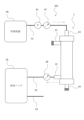
- Figure 2 shows an example of a circuit for measuring the amount of treated liquid filtered in external pressure filtration.
- a storage container 40 in which the treated liquid is stored is connected to a first port 21, which forms a treated liquid inlet, via a first tube 51.
- a pump 41 is provided midway along the first tube 51 to send the treated liquid from the storage container 40 to the ascites filter 1, and a pressure gauge 42 is located between the pump 41 and the first port 21 to measure the pressure of the treated liquid in the first tube 51.
- the circuit 100 also includes a drainage bag 45 that stores the treatment liquid discharged through the ascites filter 1.
- the drainage bag 45 is connected to the fourth port 24, which serves as the treatment liquid outlet, via a third tube 53.
- a pressure gauge 46 is provided midway through the third tube 53 to measure the pressure of the treatment liquid in the third tube 53.
- the second port 22 and the third port 23 are sealed. If one end of the tube 52 is connected to the second port 22 and is not sealed, and the other end is connected to the drainage bag 45 (not shown), the pressure can be measured under similar conditions by sealing the tube 52 using forceps, a clamp, or the like.
- the treatment liquid in the storage container 40 is introduced into the ascites filter 1 via the first tube 51 and the first port 21.
- the introduced treatment liquid passes through the hollow fiber membrane 31 from the outside to the inside, passes through the internal space of the hollow fiber membrane 31, and is discharged to the drainage bag 45 via the fourth port 24 and the third tube 53. Meanwhile, of the treatment liquid introduced into the ascites filter 1, the liquid that cannot pass through the hollow fiber membrane 31 remains in the space outside the hollow fiber membrane 31.
- FIG. 3 shows an example of a circuit for measuring the amount of treated liquid filtered in internal pressure filtration.
- the storage container 40 is connected to the third port 23, which is the treated liquid inlet, via the first tube 51.
- a pump 41 and a pressure gauge 42 are provided in the middle of the first tube 51, as in the circuit 100.
- the drainage bag 45 is connected to the second port 22, which is the treated liquid outlet, via the second tube 52.
- a pressure gauge 46 is provided in the middle of the second tube 52.
- the first port 21 and the fourth port 24 are sealed. If one side of the tube 53 is connected to the fourth port 24 and is not sealed, and the other side is connected to the drainage bag 45 (not shown), the pressure can be measured under similar conditions by sealing the tube 53 using forceps, a clamp, or the like.
- the treatment liquid in the storage container 40 is introduced into the ascites filter 1 via the first tube 51 and the third port 23.
- the introduced treatment liquid passes through the hollow fiber membrane 31 from the inside to the outside, passes through the external space of the hollow fiber membrane 31, and is discharged from the second port 22 to the drainage bag 45 via the second tube 52. Meanwhile, of the treatment liquid introduced into the ascites filter 1, the liquid that cannot pass through the hollow fiber membrane 31 remains in the space outside the hollow fiber membrane 31.
- the amount of treated liquid filtered is measured using such circuits 100, 101. That is, as described above, the pump 41 is driven to send the treated liquid from the storage container 40 to the inlet through the first tube 51. At this time, the flow rate of the treated liquid is set to be constant. That is, in the ascites filter 1, the treated liquid is filtered at a predetermined constant flow rate (e.g., 100 mL/min). Then, the pressure gauge 42 measures the pressure of the treated liquid on the inlet side, and the pressure gauge 46 measures the pressure of the treated liquid on the outlet side.
- a predetermined constant flow rate e.g. 100 mL/min
- the holes in the hollow fiber membrane 31 are blocked, and the difference between the pressure at the inlet side and the pressure at the outlet side increases.
- the amount of the liquid to be treated filtered until this pressure difference reaches a predetermined value e.g., 40 [kPa]
- a predetermined value e.g. 40 [kPa]
- V1 the amount of the liquid to be treated filtered per unit membrane area in the external pressure filtration
- V2 the amount of the liquid to be treated filtered per unit membrane area in the internal pressure filtration
- the ascites filter 1 according to the present disclosure satisfies V1>V2, more preferably satisfies the relationship 1.00 ⁇ V1/V2 ⁇ 2.00, and even more preferably satisfies the relationship 1.10 ⁇ V1/V2 ⁇ 2.00.
- the method for producing the hollow fiber membrane 31 is also called a "stretching method".
- a stretching method first, a hollow fiber having a layer (without holes) in a cylindrical shape is spun by melting raw material resin pellets (e.g., polyethylene pellets) and discharging them from a nozzle in a cylindrical shape. The spun unstretched hollow fiber is guided to a roller and wound on a bobbin.
- raw material resin pellets e.g., polyethylene pellets
- a plurality of hollow fibers are unwound from the bobbin, aligned on a codet roller, and then subjected to cold stretching and hot stretching, so that a large number of holes are formed in the layer and the diameter of each hole is enlarged.
- each stretched hollow fiber membrane precursor is unwound from the bobbin and aligned on a codet roller, and undergoes an immersion process in which it is immersed in a tank containing a dissolved hydrophilizing agent, a drying process, and then wound up on a bobbin. Through these processes, the hollow fiber membrane 31 is produced.
- the hollow fiber membrane 31 according to the present disclosure is provided with a hydrophilizing agent by undergoing the immersion process as described above.
- ethylene-vinyl alcohol copolymer (EVA) as a hydrophilizing agent adheres to the inner surface, outer surface, and pore surfaces of the hollow fiber membrane 31 that has undergone the drying process.
- EVA ethylene-vinyl alcohol copolymer
- the details of the manufacturing method of the hollow fiber membrane 31 are not particularly limited.
- the temperature during spinning of the resin pellets, the atmospheric temperature during spinning, the winding speed of the spun unstretched hollow fibers, the temperature during stretching, and the stretching schedule can each be set appropriately.
- the cold stretching process can be performed in a temperature environment of -20 degrees or more and 90 degrees or less, and the hot stretching process can be performed in a temperature environment of 100 degrees or more and 160 degrees or less.
- the stretching ratio in the cold stretching process can be selected from 1.15 times to 4.00 times, and is particularly preferably selected from 1.25 times to 3.00 times.
- the stretching ratio in the hot stretching process can be selected from 1.25 times to 6.00 times, and is particularly preferably selected from 1.40 times to 5.00 times.
- these values are merely examples, and other values can be selected.
- the number of holes on the outer surface of the hollow fiber membrane 31 is certainly greater than the number of holes on the inner surface, so that the filtration efficiency can be improved.
- the surface average pore size to 0.1 ⁇ m or more and 0.9 ⁇ m or less, clogging can be prevented, and unnecessary substances such as bacteria and cancer cells can be appropriately removed from ascites caused by cancer or cirrhosis.
- the porosity to 30% or more and 80% or less, the filtration efficiency can be improved.
- the cleaning liquid can be passed from the inside to the outside of the hollow fiber membrane at high pressure. This improves the cleaning efficiency. In other words, the cleaning of the hollow fiber membrane 31 can be completed quickly, so the overall filtration efficiency can be improved.
- Example 1 In Example 1, a polyethylene hollow fiber membrane having an inner diameter of 270 ⁇ m, an outer diameter of 380 ⁇ m, and a membrane thickness of 55 ⁇ m, and containing an ethylene-vinyl alcohol copolymer as a hydrophilizing agent, was used as the hollow fiber membrane 31. 7,056 of these hollow fiber membranes 31 were bundled to form a bundle-shaped hollow fiber body 30. Such hollow fiber body 30 was then housed in a casing 2 to form an ascites filter 1. The filling rate of the hollow fiber body 30 relative to the casing 2 was 51.7%.
- the produced hollow fiber body 30 had a membrane area (effective area on the inner surface) of 2.0 m2 .
- the surface average pore size was 0.48 ⁇ m on the outer surface and 0.50 ⁇ m on the inner surface, the material permeation pore size was 0.15 ⁇ m, and the porosity was 68.7%.
- the produced hollow fiber membrane 31 had a homogenous bamboo thicket structure in which the shape and density of the holes in the membrane were uniform at any position in the membrane thickness direction.
- Each part of the hollow fiber membrane 31 according to Example 1 (and Example 2 described below) was imaged using a scanning electron microscope.
- Figure 4A is an image of the outer surface of the hollow fiber membrane
- Figure 4B is an image of the inner surface of the hollow fiber membrane
- Figure 4C is an image of a cross section of the hollow fiber membrane 31. It can also be confirmed from Figures 4A to 4C that the membrane has a homogenous bamboo thicket structure.
- the treated fluid filtration volumes V1 and V2 per unit membrane area were measured for this ascites filter 1 using the external pressure and internal pressure filtration methods.
- the circuits 100 and 101 were first primed. Specifically, saline was introduced through the first tube 51 (see Figures 2 and 3) to fill the entire internal space of the circuits 100 and 101, including the ascites filter 1, with saline.
- Intralipos registered trademark
- A Intralipos
- B physiological saline
- This treatment liquid was placed in storage container 40, and the treatment liquid filtration volumes V1 and V2 were measured using circuits 100 and 101, respectively.
- the flow rate of the treatment liquid was 100 [mL/min].
- storage container 40 containing the treatment liquid was adjusted to 25 ⁇ 1°C in a thermostatic bath during the measurement period.
- the amount of treatment liquid treated until the pressure difference between the inlet side and the outlet side reached 40 [kPa] was then divided by the membrane area to obtain the treatment liquid filtration volumes V1 and V2 per unit membrane area.
- the obtained values of V1 and V2, and the value of V1/V2 calculated from these, are shown in Table 1.
- Example 2 In Example 2, the treated fluid filtration volumes V1 and V2 were measured for the same ascites filter 1 as in Example 1, using a treating fluid different from that in Example 1.
- the values of V1 and V2 obtained by measurement using this treating fluid, and the value of V1/V2 calculated from these values are shown in Table 1.
- Example 3 In Example 3, the treated fluid filtration volumes V1 and V2 were measured for the same ascites filter 1 as in Example 1, using a treating fluid different from those in Examples 1 and 2.
- the values of V1 and V2 obtained by measurement using this treating fluid, and the value of V1/V2 calculated from these values are shown in Table 1.
- Example 4 In Example 4, the treated fluid filtration volumes V1 and V2 were measured for the same as in Example 1 using the ascites filter 1, but using a different treating fluid from any of Examples 1 to 3.
- the values of V1 and V2 obtained by measurement using this treating fluid, and the value of V1/V2 calculated from these values are shown in Table 1.
- Example 5 A hollow fiber body 30 having a membrane area of 1.3 m2 was prepared using the same hollow fiber membrane 31 as in Example 1, and housed in a casing 2 to constitute an ascites filter 1 according to Example 5.
- the number of hollow fiber membranes 31 used in the hollow fiber body 30 was 5,488, the packing rate of the hollow fiber body 30 was 49.5%, and the effective length was 280 mm.
- the ratio of the outer surface area to the inner surface area of the hollow fiber membrane 31 excluding the portion buried by the engaging portion 32 was 1.41.
- the treated fluid filtration volumes V1 and V2 of the ascites filter 1 of Example 5 were measured using the same procedure as in Example 1.
- the obtained V1 and V2 values and the V1/V2 value calculated from these are shown in Table 2.
- Example 6 A hollow fiber body 30 having a membrane area of 2.0 m2 was prepared using the same hollow fiber membrane 31 as in Example 1, and housed in a casing 2 to constitute an ascites filter 1 according to Example 6.
- the number of hollow fiber membranes 31 used in the hollow fiber body 30 was 7,056, the packing rate of the hollow fiber body 30 was 51.7%, and the effective length was 327 mm.
- the ratio of the outer surface area to the inner surface area of the hollow fiber membrane 31 excluding the portion buried by the locking portion 32 was 1.41.
- the treated fluid filtration volumes V1 and V2 of the ascites filter 1 of Example 6 were measured using the same procedure as in Example 5.
- the obtained V1 and V2 values and the V1/V2 value calculated from these are shown in Table 2.
- Comparative Example As a comparative example, a commercially available ascites filter was used.
- the hollow fiber membrane used in the comparative example was made of polyethylene containing an ethylene-vinyl alcohol copolymer as a hydrophilizing agent, and had an inner diameter of 280 ⁇ m, an outer diameter of 380 ⁇ m, a membrane thickness of 50 ⁇ m, and a membrane area of 1.5 m2 .
- the hollow fiber body made of this hollow fiber membrane had a filling rate of 38.2% and an effective length of 213 mm. Furthermore, the ratio of the outer surface area to the inner surface area of the part of this hollow fiber membrane excluding the part buried by the locking part was 1.36.
- Figure 5A is an image of the outer surface of a hollow fiber membrane according to a comparative example taken with a scanning electron microscope
- Figure 5B is an image of the inner surface of the same hollow fiber membrane.
- the hollow fiber membrane according to the comparative example has more pores per unit area on the inner surface than on the outer surface, resulting in a non-homogeneous membrane structure with different pore densities on the outer and inner surfaces.
- the average surface pore size of the hollow fiber membrane in the comparative example was 0.29 ⁇ m on the inner surface and 0.23 ⁇ m on the outer surface, with a porosity of 61.1%.
- the material permeation pore size was 0.042 ⁇ m.
- the treated fluid filtration volumes V1 and V2 of the ascites filter of this comparative example were measured using the same procedure as in Example 5.
- the obtained V1 and V2 values and the V1/V2 value calculated from these are shown in Table 2.
- the ascites filters 1 according to Examples 1 to 6 all exhibit high filtration efficiency when used in the external pressure type (external pressure filtration method).
- This disclosure can be suitably applied to an ascites filter that processes ascites collected from the body of a patient.
Landscapes
- Chemical & Material Sciences (AREA)
- Chemical Kinetics & Catalysis (AREA)
- Engineering & Computer Science (AREA)
- Water Supply & Treatment (AREA)
- Health & Medical Sciences (AREA)
- Heart & Thoracic Surgery (AREA)
- Vascular Medicine (AREA)
- Anesthesiology (AREA)
- Biomedical Technology (AREA)
- Hematology (AREA)
- Life Sciences & Earth Sciences (AREA)
- Animal Behavior & Ethology (AREA)
- General Health & Medical Sciences (AREA)
- Public Health (AREA)
- Veterinary Medicine (AREA)
- External Artificial Organs (AREA)
Priority Applications (1)
| Application Number | Priority Date | Filing Date | Title |
|---|---|---|---|
| JP2025503828A JPWO2024181277A1 (https=) | 2023-02-28 | 2024-02-21 |
Applications Claiming Priority (2)
| Application Number | Priority Date | Filing Date | Title |
|---|---|---|---|
| JP2023-030423 | 2023-02-28 | ||
| JP2023030423 | 2023-02-28 |
Publications (1)
| Publication Number | Publication Date |
|---|---|
| WO2024181277A1 true WO2024181277A1 (ja) | 2024-09-06 |
Family
ID=92590623
Family Applications (1)
| Application Number | Title | Priority Date | Filing Date |
|---|---|---|---|
| PCT/JP2024/006368 Ceased WO2024181277A1 (ja) | 2023-02-28 | 2024-02-21 | 腹水濾過器 |
Country Status (2)
| Country | Link |
|---|---|
| JP (1) | JPWO2024181277A1 (https=) |
| WO (1) | WO2024181277A1 (https=) |
Citations (4)
| Publication number | Priority date | Publication date | Assignee | Title |
|---|---|---|---|---|
| JPS54118699A (en) * | 1978-03-06 | 1979-09-14 | Kuraray Co | Device for treating abdominal dropsy |
| JPS5749248B2 (https=) * | 1975-02-15 | 1982-10-21 | ||
| JP2016154809A (ja) * | 2015-02-26 | 2016-09-01 | 旭化成メディカル株式会社 | 濃縮器 |
| JP2019180568A (ja) * | 2018-04-04 | 2019-10-24 | 東洋紡株式会社 | 腹水濾過用の中空糸膜 |
-
2024
- 2024-02-21 JP JP2025503828A patent/JPWO2024181277A1/ja active Pending
- 2024-02-21 WO PCT/JP2024/006368 patent/WO2024181277A1/ja not_active Ceased
Patent Citations (4)
| Publication number | Priority date | Publication date | Assignee | Title |
|---|---|---|---|---|
| JPS5749248B2 (https=) * | 1975-02-15 | 1982-10-21 | ||
| JPS54118699A (en) * | 1978-03-06 | 1979-09-14 | Kuraray Co | Device for treating abdominal dropsy |
| JP2016154809A (ja) * | 2015-02-26 | 2016-09-01 | 旭化成メディカル株式会社 | 濃縮器 |
| JP2019180568A (ja) * | 2018-04-04 | 2019-10-24 | 東洋紡株式会社 | 腹水濾過用の中空糸膜 |
Also Published As
| Publication number | Publication date |
|---|---|
| JPWO2024181277A1 (https=) | 2024-09-06 |
Similar Documents
| Publication | Publication Date | Title |
|---|---|---|
| CN101888863B (zh) | 血液处理用多孔中空纤维膜 | |
| US7563376B2 (en) | Plasma purification membrane and plasma purification system | |
| CA1340585C (en) | Medical instrument and method for fabricating same | |
| US5232601A (en) | High flux hollow fiber membrane | |
| EP2326410B1 (en) | Diffusion and/or filtration device | |
| CN103282061B (zh) | 医疗材料和中空纤维膜组件 | |
| CN104902941B (zh) | 血液净化柱 | |
| JP6158787B2 (ja) | マクロ孔質濾過膜 | |
| WO2012148752A1 (en) | Combination oxygenator and arterial filter device for treating blood in an extracorporeal blood circuit | |
| WO1986002575A1 (en) | Permselective hollow yarn membrane, method of producing the same, method of separating plasma components, and plasma component separator | |
| WO2024181277A1 (ja) | 腹水濾過器 | |
| JP4683402B2 (ja) | 血液浄化用中空糸膜とその製造方法、及び血液浄化器 | |
| WO1996035504A1 (en) | Hollow-fiber membrane of polysulfone polymer and process for the production thereof | |
| JPH09308685A (ja) | 血液浄化用中空糸膜及び血液浄化器 | |
| JPS607853A (ja) | 選択透過性中空糸膜,それを用いた血漿成分分離器及び血漿成分分離装置 | |
| JP3688109B2 (ja) | 血液浄化膜 | |
| JPWO2016182015A1 (ja) | 多孔質中空糸膜及びその製造方法 | |
| JP3051510B2 (ja) | 体外循環回路装置 | |
| JP3152691B2 (ja) | 多孔質中空糸膜、人工肺および体外循環回路 | |
| JP2012019890A (ja) | 血液処理用中空糸膜、及び、中空糸膜型血液処理器 | |
| JP2932189B2 (ja) | 多孔質中空糸膜および中空糸膜型人工肺 | |
| KR20260015133A (ko) | 다공질 중공사막 및 혈액 정화용 모듈 | |
| JPH0763592B2 (ja) | 中空糸膜及びこれを用いた中空糸膜型人工肺 | |
| JP2002102626A (ja) | 白血球除去用フィルターおよび白血球除去器 | |
| JPS60249968A (ja) | 中空繊維膜型人工肺 |
Legal Events
| Date | Code | Title | Description |
|---|---|---|---|
| 121 | Ep: the epo has been informed by wipo that ep was designated in this application |
Ref document number: 24763758 Country of ref document: EP Kind code of ref document: A1 |
|
| WWE | Wipo information: entry into national phase |
Ref document number: 2025503828 Country of ref document: JP |
|
| NENP | Non-entry into the national phase |
Ref country code: DE |
|
| 122 | Ep: pct application non-entry in european phase |
Ref document number: 24763758 Country of ref document: EP Kind code of ref document: A1 |