WO2024181075A1 - 自動車窓用合わせガラス及び自動車 - Google Patents
自動車窓用合わせガラス及び自動車 Download PDFInfo
- Publication number
- WO2024181075A1 WO2024181075A1 PCT/JP2024/004282 JP2024004282W WO2024181075A1 WO 2024181075 A1 WO2024181075 A1 WO 2024181075A1 JP 2024004282 W JP2024004282 W JP 2024004282W WO 2024181075 A1 WO2024181075 A1 WO 2024181075A1
- Authority
- WO
- WIPO (PCT)
- Prior art keywords
- glass
- recess
- laminated glass
- glass sheet
- automobile
- Prior art date
- Legal status (The legal status is an assumption and is not a legal conclusion. Google has not performed a legal analysis and makes no representation as to the accuracy of the status listed.)
- Ceased
Links
Images




Classifications
-
- B—PERFORMING OPERATIONS; TRANSPORTING
- B32—LAYERED PRODUCTS
- B32B—LAYERED PRODUCTS, i.e. PRODUCTS BUILT-UP OF STRATA OF FLAT OR NON-FLAT, e.g. CELLULAR OR HONEYCOMB, FORM
- B32B1/00—Layered products having a non-planar shape
-
- B—PERFORMING OPERATIONS; TRANSPORTING
- B32—LAYERED PRODUCTS
- B32B—LAYERED PRODUCTS, i.e. PRODUCTS BUILT-UP OF STRATA OF FLAT OR NON-FLAT, e.g. CELLULAR OR HONEYCOMB, FORM
- B32B17/00—Layered products essentially comprising sheet glass, or glass, slag, or like fibres
-
- B—PERFORMING OPERATIONS; TRANSPORTING
- B32—LAYERED PRODUCTS
- B32B—LAYERED PRODUCTS, i.e. PRODUCTS BUILT-UP OF STRATA OF FLAT OR NON-FLAT, e.g. CELLULAR OR HONEYCOMB, FORM
- B32B17/00—Layered products essentially comprising sheet glass, or glass, slag, or like fibres
- B32B17/06—Layered products essentially comprising sheet glass, or glass, slag, or like fibres comprising glass as the main or only constituent of a layer, next to another layer of a specific material
- B32B17/10—Layered products essentially comprising sheet glass, or glass, slag, or like fibres comprising glass as the main or only constituent of a layer, next to another layer of a specific material of synthetic resin
- B32B17/10005—Layered products essentially comprising sheet glass, or glass, slag, or like fibres comprising glass as the main or only constituent of a layer, next to another layer of a specific material of synthetic resin laminated safety glass or glazing
- B32B17/10009—Layered products essentially comprising sheet glass, or glass, slag, or like fibres comprising glass as the main or only constituent of a layer, next to another layer of a specific material of synthetic resin laminated safety glass or glazing characterized by the number, the constitution or treatment of glass sheets
- B32B17/10036—Layered products essentially comprising sheet glass, or glass, slag, or like fibres comprising glass as the main or only constituent of a layer, next to another layer of a specific material of synthetic resin laminated safety glass or glazing characterized by the number, the constitution or treatment of glass sheets comprising two outer glass sheets
-
- B—PERFORMING OPERATIONS; TRANSPORTING
- B32—LAYERED PRODUCTS
- B32B—LAYERED PRODUCTS, i.e. PRODUCTS BUILT-UP OF STRATA OF FLAT OR NON-FLAT, e.g. CELLULAR OR HONEYCOMB, FORM
- B32B17/00—Layered products essentially comprising sheet glass, or glass, slag, or like fibres
- B32B17/06—Layered products essentially comprising sheet glass, or glass, slag, or like fibres comprising glass as the main or only constituent of a layer, next to another layer of a specific material
- B32B17/10—Layered products essentially comprising sheet glass, or glass, slag, or like fibres comprising glass as the main or only constituent of a layer, next to another layer of a specific material of synthetic resin
- B32B17/10005—Layered products essentially comprising sheet glass, or glass, slag, or like fibres comprising glass as the main or only constituent of a layer, next to another layer of a specific material of synthetic resin laminated safety glass or glazing
- B32B17/10009—Layered products essentially comprising sheet glass, or glass, slag, or like fibres comprising glass as the main or only constituent of a layer, next to another layer of a specific material of synthetic resin laminated safety glass or glazing characterized by the number, the constitution or treatment of glass sheets
- B32B17/10082—Properties of the bulk of a glass sheet
- B32B17/1011—Properties of the bulk of a glass sheet having predetermined tint or excitation purity
-
- B—PERFORMING OPERATIONS; TRANSPORTING
- B32—LAYERED PRODUCTS
- B32B—LAYERED PRODUCTS, i.e. PRODUCTS BUILT-UP OF STRATA OF FLAT OR NON-FLAT, e.g. CELLULAR OR HONEYCOMB, FORM
- B32B17/00—Layered products essentially comprising sheet glass, or glass, slag, or like fibres
- B32B17/06—Layered products essentially comprising sheet glass, or glass, slag, or like fibres comprising glass as the main or only constituent of a layer, next to another layer of a specific material
- B32B17/10—Layered products essentially comprising sheet glass, or glass, slag, or like fibres comprising glass as the main or only constituent of a layer, next to another layer of a specific material of synthetic resin
- B32B17/10005—Layered products essentially comprising sheet glass, or glass, slag, or like fibres comprising glass as the main or only constituent of a layer, next to another layer of a specific material of synthetic resin laminated safety glass or glazing
- B32B17/10009—Layered products essentially comprising sheet glass, or glass, slag, or like fibres comprising glass as the main or only constituent of a layer, next to another layer of a specific material of synthetic resin laminated safety glass or glazing characterized by the number, the constitution or treatment of glass sheets
- B32B17/10128—Treatment of at least one glass sheet
- B32B17/10137—Chemical strengthening
-
- B—PERFORMING OPERATIONS; TRANSPORTING
- B32—LAYERED PRODUCTS
- B32B—LAYERED PRODUCTS, i.e. PRODUCTS BUILT-UP OF STRATA OF FLAT OR NON-FLAT, e.g. CELLULAR OR HONEYCOMB, FORM
- B32B17/00—Layered products essentially comprising sheet glass, or glass, slag, or like fibres
- B32B17/06—Layered products essentially comprising sheet glass, or glass, slag, or like fibres comprising glass as the main or only constituent of a layer, next to another layer of a specific material
- B32B17/10—Layered products essentially comprising sheet glass, or glass, slag, or like fibres comprising glass as the main or only constituent of a layer, next to another layer of a specific material of synthetic resin
- B32B17/10005—Layered products essentially comprising sheet glass, or glass, slag, or like fibres comprising glass as the main or only constituent of a layer, next to another layer of a specific material of synthetic resin laminated safety glass or glazing
- B32B17/10165—Functional features of the laminated safety glass or glazing
- B32B17/10293—Edge features, e.g. inserts or holes
-
- B—PERFORMING OPERATIONS; TRANSPORTING
- B32—LAYERED PRODUCTS
- B32B—LAYERED PRODUCTS, i.e. PRODUCTS BUILT-UP OF STRATA OF FLAT OR NON-FLAT, e.g. CELLULAR OR HONEYCOMB, FORM
- B32B17/00—Layered products essentially comprising sheet glass, or glass, slag, or like fibres
- B32B17/06—Layered products essentially comprising sheet glass, or glass, slag, or like fibres comprising glass as the main or only constituent of a layer, next to another layer of a specific material
- B32B17/10—Layered products essentially comprising sheet glass, or glass, slag, or like fibres comprising glass as the main or only constituent of a layer, next to another layer of a specific material of synthetic resin
- B32B17/10005—Layered products essentially comprising sheet glass, or glass, slag, or like fibres comprising glass as the main or only constituent of a layer, next to another layer of a specific material of synthetic resin laminated safety glass or glazing
- B32B17/1055—Layered products essentially comprising sheet glass, or glass, slag, or like fibres comprising glass as the main or only constituent of a layer, next to another layer of a specific material of synthetic resin laminated safety glass or glazing characterized by the resin layer, i.e. interlayer
- B32B17/10761—Layered products essentially comprising sheet glass, or glass, slag, or like fibres comprising glass as the main or only constituent of a layer, next to another layer of a specific material of synthetic resin laminated safety glass or glazing characterized by the resin layer, i.e. interlayer containing vinyl acetal
-
- B—PERFORMING OPERATIONS; TRANSPORTING
- B32—LAYERED PRODUCTS
- B32B—LAYERED PRODUCTS, i.e. PRODUCTS BUILT-UP OF STRATA OF FLAT OR NON-FLAT, e.g. CELLULAR OR HONEYCOMB, FORM
- B32B3/00—Layered products comprising a layer with external or internal discontinuities or unevennesses, or a layer of non-planar shape; Layered products comprising a layer having particular features of form
- B32B3/26—Layered products comprising a layer with external or internal discontinuities or unevennesses, or a layer of non-planar shape; Layered products comprising a layer having particular features of form characterised by a particular shape of the outline of the cross-section of a continuous layer; characterised by a layer with cavities or internal voids ; characterised by an apertured layer
- B32B3/30—Layered products comprising a layer with external or internal discontinuities or unevennesses, or a layer of non-planar shape; Layered products comprising a layer having particular features of form characterised by a particular shape of the outline of the cross-section of a continuous layer; characterised by a layer with cavities or internal voids ; characterised by an apertured layer characterised by a layer formed with recesses or projections, e.g. hollows, grooves, protuberances, ribs
-
- B—PERFORMING OPERATIONS; TRANSPORTING
- B60—VEHICLES IN GENERAL
- B60J—WINDOWS, WINDSCREENS, NON-FIXED ROOFS, DOORS, OR SIMILAR DEVICES FOR VEHICLES; REMOVABLE EXTERNAL PROTECTIVE COVERINGS SPECIALLY ADAPTED FOR VEHICLES
- B60J1/00—Windows; Windscreens; Accessories therefor
-
- C—CHEMISTRY; METALLURGY
- C03—GLASS; MINERAL OR SLAG WOOL
- C03C—CHEMICAL COMPOSITION OF GLASSES, GLAZES OR VITREOUS ENAMELS; SURFACE TREATMENT OF GLASS; SURFACE TREATMENT OF FIBRES OR FILAMENTS MADE FROM GLASS, MINERALS OR SLAGS; JOINING GLASS TO GLASS OR OTHER MATERIALS
- C03C23/00—Other surface treatment of glass not in the form of fibres or filaments
-
- B—PERFORMING OPERATIONS; TRANSPORTING
- B32—LAYERED PRODUCTS
- B32B—LAYERED PRODUCTS, i.e. PRODUCTS BUILT-UP OF STRATA OF FLAT OR NON-FLAT, e.g. CELLULAR OR HONEYCOMB, FORM
- B32B2250/00—Layers arrangement
- B32B2250/03—3 layers
-
- B—PERFORMING OPERATIONS; TRANSPORTING
- B32—LAYERED PRODUCTS
- B32B—LAYERED PRODUCTS, i.e. PRODUCTS BUILT-UP OF STRATA OF FLAT OR NON-FLAT, e.g. CELLULAR OR HONEYCOMB, FORM
- B32B2315/00—Other materials containing non-metallic inorganic compounds not provided for in groups B32B2311/00 - B32B2313/04
- B32B2315/08—Glass
-
- B—PERFORMING OPERATIONS; TRANSPORTING
- B32—LAYERED PRODUCTS
- B32B—LAYERED PRODUCTS, i.e. PRODUCTS BUILT-UP OF STRATA OF FLAT OR NON-FLAT, e.g. CELLULAR OR HONEYCOMB, FORM
- B32B2605/00—Vehicles
- B32B2605/08—Cars
Definitions
- the present invention relates to laminated glass for automobile windows and automobiles.
- Patent Document 1 describes a technology in which, when an impact is applied to the cowl louvers and the area around the windshield, the rear end of the cowl louvers and the front end of the windshield, which are connected by a molding, are separated, thereby reducing the impact on people.
- Laminated glass for automobile windows such as windshields, is required to break appropriately in order to reduce the impact on people, such as pedestrians, when a vehicle collides with them.
- laminated glass for automobile windows is required to have a Head Injury Criterion (HIC) below a desired value.
- HIC Head Injury Criterion
- laminated glass for automobile windows is also required to allow automobile occupants to see outside the vehicle through the laminated glass for automobile windows.
- One aspect of the present invention aims to reduce the impact on a person when a vehicle collides with the person while not impeding the vehicle occupants' ability to see outside the vehicle.
- One aspect of the present invention is a laminated glass for automobile windows, comprising a first glass sheet, an intermediate film, and a second glass sheet, in this order from the exterior side to the interior side of the vehicle, wherein a plurality of deformed portions are provided on the interior surface of the first glass sheet and/or the second glass sheet, the deformed portions including a recess and a crack formed around the recess, and the ratio of the depth of the recess to the diameter of the recess on the surface is 2 or less.
- One aspect of the present invention provides technology that reduces the impact on a person during a collision between a vehicle and the person while not impeding the vehicle occupants' ability to see outside the vehicle.
- FIG. 1 is a front view of an automobile equipped with a laminated glass according to an embodiment of the present invention.
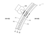
- FIG. 2 is a cross-sectional view of the laminated glass shown in FIG. 1, and is a diagram for explaining cracking of the laminated glass when an automobile crashes against a person.
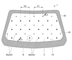
- FIG. 2 is a plan view of the laminated glass shown in FIG. 1 as viewed from the vehicle interior side.
- 4 is a cross-sectional view taken along line AA in FIG. 3.
- 5(a) is an enlarged view of a portion B including one deformed portion in FIG. 3
- FIG. 5(b) is a cross-sectional view taken along line CC in FIG. 5(a).
- FIG. 6(a) is a partial cross-sectional view of a laminated glass 1' according to a conventional technique
- FIG. 6(b) is a partial cross-sectional view of a laminated glass 1 according to an embodiment of the present invention
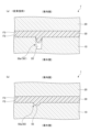
- 7A to 7C are diagrams showing modified examples of the deformation portion.
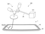
- FIG. 4 is a schematic diagram of a processing device for processing a deformed portion. 1 is a photographed image of one deformation portion formed in Example 1. 1 is a photographed image of one deformation portion formed in Example 2.
- 13A and 13B are diagrams showing a photographed image of one deformation portion formed in Example 3 and a contour shape of a recess cross section. 13 is a photographed image of one deformation portion formed in Example 4.
- 13 is a photographed image of one deformation portion formed in Example 6.
- FIG. 1 shows an example in which laminated glass for automobile windows 1 manufactured according to one embodiment of the present invention is used as window glass for an automobile 100.
- laminated glass for automobile windows (hereinafter also simply referred to as laminated glass) 1 is glass installed in an opening (window) at the front of a body 2 of an automobile 100, i.e., a windshield.
- laminated glass 1 may also be used for window glass other than a windshield, for example, a side glass, a rear glass, or a roof glass.
- Figure 2 shows a partial cross-sectional view of the laminated glass 1 shown in Figure 1.
- the laminated glass 1 comprises, from the exterior side of the vehicle toward the interior side of the vehicle, a first glass plate 10, an intermediate film 30, and a second glass plate 20, in this order.
- the first glass plate 10 and the second glass plate 20 are joined by the intermediate film 30.
- the first glass plate 10 has a first face F1 that faces the exterior side of the vehicle, and a second face F2 that faces the interior side of the vehicle.
- the second glass plate 20 has a third face F3 that faces the exterior side of the vehicle, and a fourth face F4 that faces the interior side of the vehicle.
- the material constituting the first glass plate 10 and the second glass plate 20 (hereinafter, collectively referred to simply as glass plates) in the laminated glass 1 is preferably inorganic glass.
- inorganic glass include soda lime silicate glass, aluminosilicate glass, borate glass, lithium aluminosilicate glass, and borosilicate glass.
- the glass plates are preferably formed by, for example, the float method (float glass).
- the glass sheets used to manufacture the laminated glass 1 may be untempered glass, which is made by forming molten glass into a sheet and slowly cooling it, and which has not been subjected to a tempering treatment, or tempered glass that has been tempered.
- the tempering treatment may be air-cooling tempering or chemical tempering. Even if untempered glass breaks or cracks due to impact, it is unlikely to develop fine cracks or fissures all over the surface, so that occupants can maintain visibility in the event of an accident.
- the first glass plate 10 and the second glass plate 20 may have the same thickness or may be different from each other.
- the thickness of the first glass plate 10 may be 1.1 mm or more and 3.5 mm or less.
- the thickness of the second glass plate 20 may be 0.5 mm or more and 2.3 mm or less.
- the thickness of the entire laminated glass 1 may be 2.3 mm or more and 8.0 mm or less.
- the materials, manufacturing methods, etc. of the first glass plate 10 and the second glass plate 20 may be the same or may be different from each other.
- the material of the intermediate film 30 is not particularly limited, but is preferably a thermoplastic resin.
- the material of the intermediate film 30 include thermoplastic resins such as plasticized polyvinyl acetal resins, plasticized polyvinyl chloride resins, saturated polyester resins, plasticized saturated polyester resins, polyurethane resins, plasticized polyurethane resins, ethylene-vinyl acetate copolymer resins, ethylene-ethyl acrylate copolymer resins, cycloolefin polymer resins, and ionomer resins.
- a resin composition containing a modified block copolymer hydrogenate described in Japanese Patent No. 6065221 can also be preferably used.
- plasticized polyvinyl acetal resins are preferably used because they have an excellent balance of various performances such as transparency, weather resistance, strength, adhesive strength, penetration resistance, impact energy absorption, moisture resistance, heat insulation, and sound insulation.
- the above thermoplastic resins may be used alone or in combination of two or more kinds.
- the term "plasticized" in the above plasticized polyvinyl acetal resin means that it is plasticized by adding a plasticizer. The same applies to other plasticized resins.
- the intermediate film 30 may be a resin that does not contain a plasticizer, such as an ethylene-vinyl acetate copolymer resin.
- a plasticizer such as an ethylene-vinyl acetate copolymer resin.
- the polyvinyl acetal resin include polyvinyl formal resin obtained by reacting polyvinyl alcohol (PVA) with formaldehyde, polyvinyl acetal resin in the narrow sense obtained by reacting PVA with acetaldehyde, and polyvinyl butyral resin (PVB) obtained by reacting PVA with n-butylaldehyde.
- PVB is used as a suitable material because it has an excellent balance of various properties such as transparency, weather resistance, strength, adhesive strength, penetration resistance, impact energy absorption, moisture resistance, heat insulation, and sound insulation.
- the above resins may be used alone or in combination of two or more.
- the intermediate film 30 may have either a single layer structure or a multiple layer structure.
- the intermediate film 30 may have a function other than adhesion.
- the intermediate film 30 may have one or more layers selected from a sound insulation layer, a colored transparent layer, an ultraviolet ray cut layer, an infrared ray cut layer, etc.
- the thickness of the intermediate film 30 may be 0.5 mm or more from the viewpoint of adhesiveness.
- the thickness of the intermediate film 30 may be 3 mm or less from the viewpoint of light weight and ease of handling.
- the thickness of the intermediate film 30 may be constant or may vary depending on the position.
- the manufacturing method of the laminated glass 1 includes, for example, the following steps (a) to (c).
- (a) The first glass sheet 10 and the second glass sheet 20 are laminated with the interlayer film 30 interposed therebetween to produce a laminate.
- (b) The laminate is contained inside a container such as a rubber bag, and the inside of the container is heated while reducing the pressure, and the first glass sheet 10 and the second glass sheet 20 are bonded with the interlayer film 30.
- the air pressure inside the container is, for example, -100 kPa to -65 kPa based on atmospheric pressure.
- the heating temperature of the container is, for example, 70°C to 110°C.
- the laminated glass 1 may be curved so as to be convex, either entirely or partially, towards the outside of the vehicle.
- the first glass sheet 10 and the second glass sheet 20 may be curved by bending to a desired predetermined curvature in one or two directions.
- the laminated glass 1 as shown in FIG. 1 is compound-curved, being curved in the front-to-rear and up-to-down directions of the vehicle, but may also be single-curved, being curved only in the front-to-rear or up-to-down direction.
- the radius of curvature of the laminated glass 1 may be 200 mm or more and 300,000 mm or less.
- the first glass sheet 10 and the second glass sheet 20 are bent before the above step (a).
- the bending is performed in a state where the glass is softened by heating.
- the heating temperature of the glass during bending is, for example, 550°C to 700°C.
- the first glass sheet 10 and the second glass sheet 20 may be bent separately, or may be overlapped and bent simultaneously.
- the bending may be performed by gravity forming or press forming, or may include both.
- a shielding layer or light-shielding layer 40 may be provided on the periphery of the laminated glass 1 to protect the sealant or the like that adheres and holds the laminated glass 1 to the vehicle body.
- the shielding layer 40 can be formed, for example, by applying a ceramic color paste of a low brightness color such as black, gray, or brown, which contains a fusible glass frit containing a black pigment, and then firing the paste.
- the shielding layer 40 may be formed on one or more of the second face F2, the third face F3, and the fourth face F4 (FIG. 2) of the laminated glass 1, preferably on the periphery of at least one of the second face F2 and the fourth face F4 (FIG. 2).
- the shielding layer 40 may be provided over a position 10 mm to 300 mm from the peripheral edge of the glass plate.
- the area excluding the area covered by the shielding layer 40 formed on the laminated glass (also called the light-shielding area) is the see-through area 5.
- the see-through area 5 is an area that allows the occupants of the automobile 100 to see the outside of the automobile 100. In other words, the occupants of the automobile 100 can see the outside of the vehicle through the viewing area 5.
- laminated glass 1 for automobile windows is required to break appropriately in order to reduce the impact on people, such as pedestrians and cyclists, when an automobile collides with them.
- laminated glass 1 is required to have a Head Injury Criterion (HIC) that is equal to or lower than a desired value (e.g., 1000 or less, preferably 650 or less).
- HIC Head Injury Criterion
- the laminated glass 1 breaks when it collides with a person.
- the laminated glass 1 collides with a person 200
- the laminated glass 1 is pushed from the outside of the vehicle toward the inside of the vehicle.
- tensile stress is generated on the second surface F2, which is the surface of the first glass sheet 10 facing the vehicle interior.
- the second surface F2 has a portion (scratch, recess, crack, melting mark, etc.) that is different from the properties that the entire glass has on average, or that has been modified or deformed, the first glass sheet 10 may break from that portion.
- Tensile stress is also generated on the fourth surface F4, which is the surface of the second glass sheet 20 facing the vehicle interior.
- the second glass sheet 20 may break from that portion.
- cracking fracture
- the fourth surface F4 which is the surface of the second glass sheet 20 facing the inside of the vehicle, is exposed, cracking is particularly likely to initiate from the fourth surface F4 of the laminated glass 1 as a whole.
- FIG. 3 shows a plan view of the laminated glass 1 according to this embodiment as seen from the inside of the vehicle.
- FIG. 4 shows a cross-sectional view of the laminated glass 1 of FIG. 3 taken along line A-A.
- FIG. 3 and FIG. 4 show a plurality of deformed portions 50 formed in the laminated glass 1 (details of the shape of the deformed portions are omitted in FIG. 3 and FIG. 4).
- the deformed portions 50 refer to minute regions in which the surface shape of the glass sheet has been changed, more specifically, minute regions in which the surface of the glass sheet has been changed to form portions that are depressed from the original surface level.
- the deformed portions 50 are scattered in the surface direction, preferably in the see-through region 5, throughout the laminated glass 1.
- the deformed portions 50 are scattered throughout the laminated glass 1, so that when the occupant looks outside the vehicle (the outside of the automobile), the occupant's view is not obstructed (external visibility can be ensured). In addition, the ease of breaking during a collision can be ensured throughout the laminated glass 1.
- the deformation portion (also called the surface deformation portion) 50 can be formed on one or more surfaces of the first glass sheet 10 and the second glass sheet 20 of the laminated glass.
- the deformation portion 50 is formed on the vehicle interior surface (second surface F2) of the first glass sheet 10 and/or the vehicle interior surface (fourth surface F4) of the second glass sheet 20, which are likely to crack first when an impact is received from outside the vehicle, so that cracking of the laminated glass 1 is more likely to start when a person collides with the car, and the impact on the person can be effectively reduced and the person is protected.
- the deformation portion 50 is formed on the vehicle interior surface (fourth surface F4) of the second glass sheet 20, which is more likely to crack when an impact is received from outside the vehicle.
- the deformation portion 50 is formed on both the surface (second surface F2) of the first glass sheet 10 facing the vehicle interior side and the surface (fourth surface F4) of the second glass sheet 20 facing the vehicle interior side, that is, as shown in FIG. 3 and FIG.
- the deformation portion 50 includes a plurality of first deformation portions 50a formed on the entire second surface F2 of the first glass sheet 10 in the surface direction, and a plurality of second deformation portions 50b formed on the entire fourth surface F4 of the second glass sheet 20 in the surface direction, the strength of the entire laminated glass 1 can be appropriately reduced, which is preferable.
- both the plurality of first deformation portions 50a and the plurality of second deformation portions 50b are scattered apart in the surface direction of the glass sheets, so that the external visibility of the laminated glass 1 can be ensured.
- the first deformation portion 50a and the second deformation portion 50b are each arranged in a lattice pattern in a planar view, but the arrangement of the deformation portion 50 in the planar direction is not limited to a lattice pattern and may be, for example, a staggered pattern. Also, when looking at the overall arrangement of the deformation portion 50 in a planar view, that is, when looking at the first deformation portion 50a and the second deformation portion 50b together, in the example shown in Figure 3, the arrangement is staggered, but this overall arrangement is not limited to a staggered pattern and may be, for example, a lattice pattern.
- the pitch P1 (FIG. 3) of the first deformation portions 50a may be preferably 1 mm or more and 200 mm or less, more preferably 10 mm or more and 100 mm or less, and even more preferably 20 mm or more and 100 mm or less.
- the pitch P1 is the distance between the center position of one first deformation portion 50a and the center position of another first deformation portion 50a arranged closest to it.
- the center position of the deformation portion 50 can be the center position of a recess (described later) in the deformation portion 50.
- the pitch P1 may be uniform over the perspective region 5 or may vary depending on the location, and in the latter case, the average value is used.
- the first deformation portions 50a are too close to each other, and the compressive stress generated on the surface is continuously distributed in the surface direction, which makes the glass plate less likely to break.
- the first deformation portions 50a which are the starting points for cracks, are appropriately distributed on the surface on the inside of the vehicle (second surface F2), making the laminated glass 1 more likely to crack when an impact is applied to the laminated glass 1 from the outside of the vehicle.
- the pitch P2 of the second deformation portion 50b may be preferably 1 mm or more and 200 mm or less, more preferably 10 mm or more and 100 mm or less, and even more preferably 20 mm or more and 100 mm or less.
- the effect of setting the pitch P2 of the second deformation portion 50b to 1 mm or more and 200 mm or less is the same as the effect of the pitch P1.
- the first deformation portion 50a and the second deformation portion 50b do not overlap in a planar view, but the first deformation portion 50a and the second deformation portion 50b may overlap in part or in whole. Furthermore, the first deformation portion 50a and the second deformation portion 50b may be aligned in the thickness direction of the glass plate, that is, the first deformation portion 50a and the second deformation portion 50b may be arranged on a single straight line parallel to the thickness direction. If the first deformation portion 50a and the second deformation portion 50b overlap in a planar view, this is preferable because it makes it easier for a crack to propagate in the thickness direction of the glass plate when the laminated glass 1 collides with a person 200.
- FIG. 5(a) shows an enlarged view of portion B in FIG. 3, which includes one deformation portion 50 (second deformation portion 50b).
- FIG. 5(b) shows a cross-sectional view taken along line C-C in FIG. 5(a). Note that the shape of the deformation portion 50 shown in FIGS. 5(a) and (b) is schematic for ease of explanation.
- the deformation portion 50 includes a recess 55 and a crack 56 formed around the recess.
- Such a deformation portion 50 can be formed, for example, by laser irradiation (described in detail later).
- the presence of the recess 55 makes it easier to recognize the presence of the deformed portion 50 during inspection, etc., and makes it easier to inspect whether the deformed portion 50 is reliably formed in the obtained product. Also, during the bending process to curve the glass plate, the stress attempting to close the crack 56 is thought to escape to the recess 55, which can prevent the crack 56 formed around the recess 55 from closing. Furthermore, the crack 56 mainly contributes to appropriately reducing the strength of the glass plate and making it easier for the glass plate to break in an appropriate manner in the event of a collision. Furthermore, the recess 55 may be a portion formed by laser ablation.
- the recess 55 may have a predetermined depth L from the surface of the glass plate (for example, the fourth surface F4 in the case of the deformed portion 50b) and a predetermined diameter d.
- the diameter d is the planar diameter, more specifically, the circle-equivalent diameter of the opening of the recess 55 on the surface. That is, it is the diameter of a circle having the same area as the area of the recess 55 on the surface.
- the diameter d is the diameter of the recess 55, but the shape of the recess 55 in the planar view is not necessarily circular, and the diameter d can be calculated from the area of the opening of the recess 55.
- the depth L is the distance from the surface of the glass plate to the deepest position of the recess 55.
- the cross-sectional shape of the recess 55 cut in the thickness direction of the glass plate is a partial ellipse, but the cross-sectional shape of the recess 55 may be rectangular or a part of a rectangle, and a bottom surface may be formed.
- the contour of the cross-sectional shape of the recess 55 has a shape in which the tangent changes continuously (a curved shape that does not include sharp corners) except for the intersection with the glass plate surface, since this prevents strong scattering of light at the corners.
- the ratio (L/d) of the depth L to the diameter d of the recess 55 is 2 or less. This ensures a certain degree of the diameter d, making it easier to check the formation of the deformed portion 50 during product inspection, and in the bending process of the glass sheet, the stress that tries to close the crack 56 is more likely to escape to the recess 55, preventing the crack 56 around the recess 55 from closing. Furthermore, as shown in FIG. 6(b), when the recess 55 is a recess included in the first deformed portion 50a (a recess formed in the first glass sheet 10), the surface on which the recess 55 is formed (the second surface F2) comes into contact with the intermediate film 30.
- the intermediate film 30 can also enter the recess 55, preventing the formation of a cavity between the surface of the recess 55 and the intermediate film 30, or making the formed cavity smaller. This action will be described with reference to FIGS. 6(a) and (b).
- FIG. 6(a) shows a partial cross-sectional view of a laminated glass 1' according to a conventional technology
- FIG. 6(b) shows a partial cross-sectional view of a laminated glass 1 according to an embodiment of the present invention.
- FIGS. 6(a) and (b) details of the deformed portion such as a crack are omitted, and only the recess is shown.
- a deformed portion 50' (first deformed portion 50a') is formed on the surface (second surface F2) of the first glass sheet on the vehicle interior side.
- the value (L/d) of the ratio of the depth L to the diameter d of the recess 55' included in the deformed portion 50' exceeds 2.
- the interlayer film 30 penetrates into the recess 55 and can be closely attached to the surface of the recess 55, so that the cavities between the recess 55 and the interlayer film 30 in the laminated glass 1 are not noticeable, and the external visibility of the automobile window can be improved.
- the value of the ratio (L/d) may be preferably 1 or less, more preferably 0.8 or less, and even more preferably 0.5 or less. There is no particular lower limit to (L/d), and (L/d) may be greater than 0, but may be, for example, 0.05 or more, or 0.1 or more.
- the depth L of the recess 55 may preferably be more than 0 ⁇ m and not more than 100 ⁇ m, more preferably 1 ⁇ m or more and not more than 50 ⁇ m, and even more preferably 1 ⁇ m or more and not more than 30 ⁇ m.
- the depth L enhances the above-mentioned effect of preventing the crack 56 from closing during bending.
- the intermediate film 30 can enter the recess 55 more easily (FIG. 6), and the cavity between the recess 55 and the intermediate film 30 is not noticeable, thereby improving the external visibility of the vehicle window.
- the value of the ratio of the depth L to the thickness of the glass sheet may preferably be 0.001 or more and 0.1 or less, more preferably 0.001 or more and 0.05 or less.
- the deformation portion 50 is formed on the second surface F2 of the first glass plate 10 (first deformation portion 50a), it is preferable that no cavity or space is formed between the recess 55 and the intermediate film 30, or, even if one is formed, the distance between the recess 55 and the intermediate film 30 is smaller than the wavelength of visible light.
- the surface (inner surface) of the recess 55 is preferably smooth.
- the surface roughness Ra of the surface of the recess 55 is preferably smaller than the surface roughness Ra of the second surface F2 of the first glass plate 10. This allows the intermediate film 30 that has entered the recess 55 to adhere closely to the inner surface of the recess 55, further suppressing the formation of cavities.
- the surface roughness Ra in this specification is the arithmetic mean roughness Ra value obtained by stylus-type measurement using a surface roughness measuring instrument in accordance with JIS B 0601:1994.
- the surface of the recess 55 is a smooth fire-making surface.
- the fire-making surface here is a surface where glass melted by laser irradiation comes into contact with air and solidifies. Therefore, the fictive temperature near the surface of the recess 55 may be higher than the fictive temperature of the second surface F2 in the area other than the deformation portion 50.
- the cracks 56 may be formed around the recesses 55 as shown in FIG. 5(a).
- the number of cracks 56 in one deformation portion 50 may be one or more.
- the shape, formation position, etc. of the cracks 56 are not particularly limited.
- the cracks 56 may be formed away from the recesses 55, or may be formed so as to be connected to the recesses 55 and extend from the recesses 55.
- the crack 56 that reaches the surface of the glass plate as described above is easily formed by irradiating the laser light from the bottom surface (described later) side of the glass plate.
- the crack 56 is formed along the circumferential direction of the recess 55 in a plan view.
- the shape of the crack 56 is an arc along the circumferential direction of the recess 55 in a plan view.
- a crack 56 is included on each side.
- the diameter D of the extension region of the deformed portion 50 in a plan view is the diameter of the smallest circle that contains the recess 55 and the crack 56 around it.
- the diameter D of the extension region of the deformed portion 50 may be preferably 20 ⁇ m or more and 200 ⁇ m or less, more preferably 30 ⁇ m or more and 100 ⁇ m or less.
- the deformed portion 50 is less noticeable to the visual inspection of the occupant, and the obstruction of the occupant's field of vision is suppressed, that is, the external visibility of the automobile window can be improved. In addition, it is easier to ensure robustness as a vehicle window under normal conditions.
- the upper limit of the diameter D, 200 ⁇ m is smaller than the size of a black spot (500 ⁇ m) permitted by the Japanese Automotive Standards Organization (JASO).
- the ratio (D/d) of the diameter D of the extension region of the deformation portion 50 to the diameter d of the recess 55 in the plan view may be preferably 1.2 or more and 4 or less, more preferably 1.2 or more and 3 or less.
- FIG. 7(a) to (c) show modified examples of the deformation portion 50 of this embodiment.
- FIG. 7(a) is a view corresponding to FIG. 5(b) and shows modified shapes of the recesses 55.
- the direction of the axis Ax of the recesses 55 does not necessarily need to be parallel to the normal direction of the surface on which the recesses 55 are open, and may form an angle ⁇ of 60° or less with respect to the direction of the normal N. That is, the cross-sectional shape of the recesses 55 cut in the thickness direction of the glass plate may be asymmetric with respect to the normal N passing through the center O of the recesses 55 (it may be a shape that does not have symmetry).
- the axis Ax of the recesses 55 is a straight line extending from the center O of the recesses 55 (the center if the opening of the recesses 55 is circular, or the centroid if the opening is a shape other than circular) to the deepest position of the recesses 55.
- Such an inclination of the axis Ax of the recesses 55 with respect to the normal N corresponds to the inclination of the laser irradiation direction with respect to the normal N when the deformation portion 50 is formed by laser irradiation.
- the direction of the axis Ax of the recesses 55 in the multiple deformation parts 50 may have a distribution. That is, the deformation parts 50 may be formed so that the axial directions of the multiple recesses 55 are at various angles with respect to the normal direction. For example, the angle of the axial direction of the recesses 55 in one deformation part 50 with respect to the normal direction may be different from the angle of the axial direction of the recesses 55 in the adjacent deformation parts 50 with respect to the normal direction. This allows different directions in which light refracts and scatters to be mixed within the surface of the glass plate, and the possibility of multiple recesses 55 being simultaneously visible to the occupant can be avoided.
- Such a difference in the inclination of the axial direction of the recesses 55 can be obtained by forming the multiple recesses 55 while changing the irradiation direction of the laser. Furthermore, by using a processing device that combines a galvanometer scanner and a laser, it is easy to control the irradiation direction.
- a linear crack (hereinafter also referred to as an internal linear crack 58) may be formed inside the glass sheet, separated from the deformation portion 50.
- Fig. 7(b) shows a configuration in which an internal linear crack 58 is formed in a recess 55 having an axis Ax, which is a normal line passing through the center O of the recess 55, as shown in Fig. 5(b).
- Fig. 7(c) shows a configuration in which an internal linear crack 58 is formed in a recess 55 having an axis Ax inclined with respect to the normal N, as shown in Fig. 7(a).
- Figs. 7(b) shows a configuration in which an internal linear crack 58 is formed in a recess 55 having an axis Ax inclined with respect to the normal N, as shown in Fig. 7(a).
- the internal linear crack 58 may be along the axis Ax of the recess 55.
- the internal linear crack 58 makes the glass sheet, and thus the laminated glass 1 obtained, more likely to break appropriately upon impact, thereby improving the effect of reducing the impact on people.
- the length of the internal linear crack 58 may be 100 ⁇ m or more and 1000 ⁇ m or less.
- the shape of the deformation portion 50, the diameter d of the recess 55, the depth L (L/d), the diameter D of the extension region in a plan view, and other dimensions of the deformation portion 50 may be the same or different between the first deformation portion 50a and the second deformation portion 50b.
- the deformation portion 50 is formed on one of the two main surfaces of the glass sheet 10 that was in contact with the molten metal, such as molten tin or molten tin alloy, during manufacturing (hereinafter referred to as the bottom surface). This point will be explained below.
- the float method is a method of forming molten glass by floating it on molten metal such as molten tin in a float bath.
- molten metal such as molten tin
- the bottom surface that was in contact with the molten tin contains tin near the surface, but the top surface, which is the main surface opposite the bottom surface and was not in contact with the molten tin, contains almost no tin.
- an ion exchange reaction between the sodium ions in the glass and the hydrogen ions in the outside air proceeds, and a surface hydration layer is gradually formed. Since the surface hydration layer has a low hardness, the brittleness of the top surface decreases over time, making it difficult for cracks to form and grow.
- the breaking strength increases over time.
- a person such as a pedestrian is hit by a car, it is difficult for the laminated glass 1 to start cracking, and the function of protecting the person may be insufficient.
- the effect of tin which is an asymmetric ion, inhibits the ion exchange reaction between hydrogen ions and sodium ions, so the formation of a surface hydration layer does not proceed easily. Therefore, by forming the deformation portion 50 on the bottom surface, the breaking strength is less likely to change over time, and the function of protecting people is maintained for a long period of time.
- the deformation portion 50 on the bottom surface that contains a large amount of tin.
- the glass plates 10, 20 are preferably arranged so that the surfaces (second surface F2 and fourth surface F4) facing the vehicle interior are the bottom surfaces.
- the bottom surface that contains a large amount of metal such as tin has a significantly improved light absorption rate, especially in the UV region. Therefore, when the deformation portion 50 is formed by laser irradiation, there is also the advantage that processing can be performed with lower energy irradiation.
- the bottom surface which contains a large amount of tin
- the top surface which contains almost no tin
- a tin-containing layer with a thickness of 5 to 15 ⁇ m can be detected by quantitatively measuring the tin concentration using X-ray fluorescence or EPMA.
- the maximum value may be preferably 350 MPa or less, more preferably 250 MPa or less.
- the minimum value may be preferably 60 MPa or more, more preferably 80 MPa or more.
- a maximum value of 350 MPa or less makes the laminated glass 1 appropriately more likely to break in the event of a collision, improving the effect of reducing the impact on people.
- a minimum value of 60 MPa or more can suppress breakage of the laminated glass 1 due to flying stones.
- the arithmetic mean roughness Ra of the roughness curve defined in JIS B 0601-2013 of the second surface F2 of the first glass plate 10 and the fourth surface F4 of the second glass plate 20 can be 0.1 nm or more and 1000 nm or less.
- the method for forming the deformed portion 50 is not particularly limited, and may be by laser, electron beam irradiation, mechanical processing, etc., but among these, the method using laser light irradiation is preferred.
- Laser light has high directivity or convergence, and allows irradiation with a small spot diameter (diameter at the focused position), so a minute area can be locally heated to form the deformed portion 50 with precise size and arrangement.
- FIG. 8 shows a schematic diagram of a processing device 300 for forming the deformation portion 50.
- the processing device 300 may include a laser light irradiation device 310 and a scanning device 320.
- the scanning device 320 may be a galvanometer scanner, a polygon scanner, or the like.
- the direction of the laser light LB emitted from the laser light irradiation device 310 can be adjusted by the scanning device 320. This allows the direction of the laser light LB to be arbitrarily changed three-dimensionally, and for example, even for a curved glass plate, the laser light can be more reliably irradiated at a desired angle at a desired position on the main surface of the glass plate.
- the laser light LB is irradiated from the vehicle interior side (the fourth surface F4 side) of the second glass sheet 20 that constitutes the laminated glass 1, but the laser light may also be irradiated from the vehicle exterior side (the third surface F3 side) of the second glass sheet 20 to form the deformation portion 50 on the vehicle interior surface.
- the irradiation conditions can be set so that the focus is on the vehicle interior surface of the glass sheet.
- the laser light LB can be irradiated at a stage before the glass sheets 10, 20 are laminated (before the above-mentioned step (a)). That is, after forming the deformed portion 50 on the vehicle interior surface of the first glass sheet 10 and/or the second glass sheet 20, the laminate can be constructed via the intermediate film 30. Alternatively, if the deformed portion 50 to be formed is the second deformed portion 50b, the laser light LB can be irradiated from the vehicle interior side of the laminated glass 1 after the laminated glass 1 is constructed.
- nonlinear absorption or linear absorption may be used.
- the photon density may be 1 ⁇ 10 8 W/cm 2 or more and 1 ⁇ 10 14 W/cm 2 or less.
- nonlinear absorption multiphoton absorption occurs. The probability of multiphoton absorption occurring is nonlinear absorption, and increases dramatically as the photon density increases. For example, the probability of two-photon absorption occurring is proportional to the square of the photon density.
- one-photon absorption occurs at any position in the thickness direction of the glass plate due to the photon density.
- One-photon absorption is proportional to the photon density.
- the deformed portion 50 is easily formed to appear on the surface.
- the conditions for irradiating the laser light LB depend on the composition of the glass plates contained in the laminated glass 1, but are not particularly limited as long as the conditions are such that the recess 55 and the crack 56 are formed around it.
- the wavelength of the laser light LB is preferably at least partially transparent. More specifically, the wavelength of the laser light LB may be 250 nm or more and 5000 nm or less, and preferably 310 nm or more and 3000 nm or less. With a wavelength in the above range, the absorption coefficient ⁇ can be set to an appropriate range.
- Light sources of laser light include near-infrared lasers such as Yb fiber lasers (wavelengths: 1000 nm to 1100 nm), Yb disk lasers (wavelengths: 1000 nm to 1100 nm), Nd:YAG lasers (wavelengths: 1064 nm), and high-power semiconductor lasers (wavelengths: 808 nm to 980 nm).
- near-infrared lasers such as Yb fiber lasers (wavelengths: 1000 nm to 1100 nm), Yb disk lasers (wavelengths: 1000 nm to 1100 nm), Nd:YAG lasers (wavelengths: 1064 nm), and high-power semiconductor lasers (wavelengths: 808 nm to 980 nm).
- Light sources of laser light may also be UV lasers (wavelengths: 310 nm to 360 nm), green lasers (wavelengths: 510 nm to 540 nm), Ho:YAG lasers (wavelengths: 2080 nm), Er:YAG lasers (2940 nm), and lasers using mid-infrared optical parametric oscillators (wavelengths: 2600 nm to 3450 nm).
- Light sources of laser light may also be LD-pumped solid-state (Diode Pumped Solid State: DPSS) lasers combined with wavelength conversion elements.
- DPSS LD-pumped solid-state
- the laser light LB may be irradiated in a pulsed or continuous oscillation manner.
- the pulsed oscillation is preferable from the viewpoint of reducing unintended damage to the vicinity of the irradiated area.
- the pulse operation mode is not particularly limited, but the burst pulse mode is preferable because it allows high-power irradiation and shortens the irradiation time.
- a nanosecond pulse laser, a picosecond pulse laser, a femtosecond pulse laser, etc. can be used.
- Other conditions for the laser light irradiation may include a pulse width of 0.0001 ns to 100 ns, a pulse energy of 10 ⁇ J to 1000 ⁇ J, a number of irradiations of 1 to 1000, and a repetition frequency of 1 kHz to 10,000 kHz.
- the irradiation angle of the laser light (angle with respect to the normal direction of the main surface of the glass plate at the irradiation position) can be set to an irradiation angle corresponding to the angle ⁇ of the recess 55 to be formed (FIG. 7(a)).
- the irradiation angle of the laser light and the angle ⁇ of the recess 55 have different values due to the refraction of the laser light on the surface of the glass plate. The difference in angle can be easily calculated from the refractive index of the glass plate.
- a plurality of deformations 50 on the main surface of the glass plate can be formed by changing the irradiation angle of the laser light.
- One embodiment of the present invention may be a method for manufacturing a glass sheet for an automobile window, in which a plurality of deformed portions are provided on the surface of the glass sheet facing the interior of the vehicle, spaced apart in the planar direction, the deformed portions include recesses and cracks formed around the recesses, and the ratio of the depth of the recesses to the diameter of the recesses on the surface is 2 or less.
- An embodiment of the present invention may be a method for manufacturing laminated glass for automobile windows, which comprises, from the vehicle exterior side toward the vehicle interior side, a first glass sheet, an intermediate film, and a second glass sheet, in this order, in which a plurality of deformed portions are provided on the vehicle interior surface of the first glass sheet and/or the second glass sheet, the deformed portions include a recess and a crack formed around the recess, and the ratio of the depth of the recess to the diameter of the recess on the surface is 2 or less.
- the first deformed portion 50a and the second deformed portion 50b can be formed on the first glass sheet 10 and the second glass sheet 20, respectively, and then the first glass sheet 10 and the second glass sheet 20 can be laminated via the intermediate film 30 to obtain the laminated glass 1 (for example, the above-mentioned steps (a) to (c)). Also, after the bending step, the deformed portion 50 can be formed by irradiating both the first glass sheet 10 and the second glass sheet 20 with laser light.
- the laser light LB can be scanned, for example, twice across the viewing area 5, to form the first deformed portion 50a on the surface of the first glass sheet 10 facing the vehicle interior in one of the scans, and the second deformed portion 50b in the second glass sheet 20 in the other scan.
- the conditions for irradiating the laser light, particularly the wavelength of the laser are adjusted so that the absorptance of the laser light in the first glass sheet and/or the second glass sheet is greater than the absorptance of the laser light in the intermediate film. This method can prevent misalignment of the first deformed portion 50a and the second deformed portion 50b in a plan view.
- the deformed portion 50 when forming the deformed portion 50 after obtaining the laminated glass 1, the deformed portion 50 can be formed in both the first glass plate 10 and the second glass plate 20 with a single scan of the laser light LB.
- the laser light LB is focused at two or more different positions on the optical axis of the laser light LB, i.e., in both the first glass plate 10 and the second glass plate 20, with a single scan.
- This method is suitable for obtaining a configuration in which the first deformed portion 50a and the second deformed portion 50b are arranged to overlap when viewed in a plan view.
- a laser may be applied after the bending process of the first glass sheet and the second glass sheet. This can prevent the shape and size of the deformed portion 50 from changing during the bending process, and thus prevent the function from changing.
- Example 1 ⁇ Preparation of samples for fracture stress measurement> (Example 1)
- a glass sample 100 mm x 100 mm x 2 mm thick
- a laser was irradiated from the bottom surface side to one central location in the surface of the glass sample.
- Table 1 shows the laser irradiation conditions. Among the irradiation conditions, the "number of irradiations" is the number of times the laser was irradiated.
- the "irradiation angle” is the angle with respect to the normal direction of the bottom surface of the glass plate at the irradiation position.
- An irradiation angle of 0° means that irradiation is performed in the normal direction of the irradiated surface (bottom surface).
- all deformation portions were formed by laser irradiation with an irradiation angle of 0°.
- the laser processing device used for the laser irradiation is composed of a laser light irradiation device (LD-excited solid-state laser) and a galvano scanner, which is a scanning device.
- the laser processing device itself is fixed in position, but a device that can irradiate the laser beam at various angles was used.
- the aperture ratio and working distance of the lens were set so that the spot diameter of the laser light on the glass plate surface was 32 ⁇ m in 1/ e2 diameter.
- the glass sample was placed in an electric heating furnace and heated at 658°C for 200 seconds, a heating process equivalent to that used in the usual bending process.
- Example 2 to 4 Glass samples of Examples 2 to 4 were obtained in the same manner as Example 1, except that the laser irradiation conditions were changed as shown in Table 1. In Example 3, the deformed portion was formed by laser irradiation at an irradiation angle of 28.00°. In the samples of Examples 2 and 3, it was confirmed that an internal linear crack was formed, but in the sample of Example 4, no internal linear crack was formed.
- Example 5 A glass sample was obtained in the same manner as in Example 1, except that no laser irradiation was performed.
- Example 6 A glass sample of Example 6 was obtained in the same manner as in Example 1, except that the laser irradiation conditions were changed as shown in Table 1. In the sample of Example 6, no cracks were formed around the recesses, and no internal linear cracks were formed.
- the focal depth affects the formation of internal linear cracks.
- the focal depth is proportional to the square of the spot diameter of the laser light and inversely proportional to the wavelength of the laser light.
- the spot diameter was large at 32 to 53 ⁇ m, the wavelength was short at 355 nm, and the focal depth was long, so the laser light reached the inside of the glass sample and internal linear cracks were formed.
- the spot diameter was small at 14 ⁇ m, the wavelength was long at 1064 nm, and the focal depth was short, so the laser light had difficulty reaching the inside of the glass sample and internal linear cracks were not formed.
- Figures 9 to 13 show photographs (1000x magnification for Example 1, and 2000x magnification for Examples 2 to 4 and 6) of a deformation part in the glass samples of Examples 1 to 4 and Example 6, respectively.
- the lower part of Figure 11 shows the analysis results of the contour of the recess in Example 3.
- Example 1 to 4 which have a deformed portion including a recess and a crack formed around it, the maximum value of the fracture stress was 350 MPa or less, and the minimum value was 60 MPa or more.
- Examples 5 and 6 which do not have a deformed portion including a recess and a crack formed around it, the maximum value of the fracture stress exceeded 350 MPa.
- the maximum value of the fracture stress was about 30 MPa lower than in Example 4, in which no internal linear crack was formed, and it was found that the glass plate was more likely to break appropriately in the event of a collision.
- a glass sample (300 mm x 300 mm x 2 mm thick) was cut out from a glass plate having a soda lime silicate glass composition obtained by the float process, and was irradiated with a laser from the bottom surface side. Irradiation was performed intermittently at 81 points scattered in a square lattice pattern with a pitch of 30 mm.
- the laser irradiation conditions are as shown in Table 1. After the laser irradiation, the glass sample was placed in an electric heating furnace and was heated at 658°C for 200 seconds as a heat treatment equivalent to a commonly performed bending process.
- the two glass samples that had been irradiated with laser and heated were stacked with the bottom surfaces facing the same direction (so that the bottom surfaces of both glass samples faced upwards) via an interlayer film (PVB resin) and pressed together to form a laminated glass.
- a laminated glass sample was obtained in which a 2 mm thick glass sample, a 0.76 mm thick interlayer film, and a 2 mm thick glass sample were stacked.
- laminated glass for automobile windows in which the deformation portions of Examples 1 to 4 are provided on the vehicle-interior surface of the first glass sheet and/or the second glass sheet at multiple locations spaced apart in the planar direction, can provide a technology that reduces the impact on people in the event of a collision between the automobile and the person, while not impeding the automobile occupants' ability to see outside the automobile.
Landscapes
- Chemical & Material Sciences (AREA)
- Engineering & Computer Science (AREA)
- Chemical Kinetics & Catalysis (AREA)
- General Chemical & Material Sciences (AREA)
- Mechanical Engineering (AREA)
- Life Sciences & Earth Sciences (AREA)
- Geochemistry & Mineralogy (AREA)
- Materials Engineering (AREA)
- Organic Chemistry (AREA)
- Joining Of Glass To Other Materials (AREA)
Priority Applications (4)
| Application Number | Priority Date | Filing Date | Title |
|---|---|---|---|
| EP24763559.2A EP4674823A1 (en) | 2023-03-02 | 2024-02-08 | Laminated glass for automobile window and automobile |
| JP2025503720A JP7720507B2 (ja) | 2023-03-02 | 2024-02-08 | 自動車窓用合わせガラス及び自動車 |
| CN202480009818.1A CN120677133A (zh) | 2023-03-02 | 2024-02-08 | 汽车窗用夹层玻璃及汽车 |
| US19/308,685 US20250375949A1 (en) | 2023-03-02 | 2025-08-25 | Laminated glass for automobile window and automobile |
Applications Claiming Priority (2)
| Application Number | Priority Date | Filing Date | Title |
|---|---|---|---|
| JP2023032021 | 2023-03-02 | ||
| JP2023-032021 | 2023-03-02 |
Related Child Applications (1)
| Application Number | Title | Priority Date | Filing Date |
|---|---|---|---|
| US19/308,685 Continuation US20250375949A1 (en) | 2023-03-02 | 2025-08-25 | Laminated glass for automobile window and automobile |
Publications (1)
| Publication Number | Publication Date |
|---|---|
| WO2024181075A1 true WO2024181075A1 (ja) | 2024-09-06 |
Family
ID=92589633
Family Applications (1)
| Application Number | Title | Priority Date | Filing Date |
|---|---|---|---|
| PCT/JP2024/004282 Ceased WO2024181075A1 (ja) | 2023-03-02 | 2024-02-08 | 自動車窓用合わせガラス及び自動車 |
Country Status (5)
| Country | Link |
|---|---|
| US (1) | US20250375949A1 (https=) |
| EP (1) | EP4674823A1 (https=) |
| JP (1) | JP7720507B2 (https=) |
| CN (1) | CN120677133A (https=) |
| WO (1) | WO2024181075A1 (https=) |
Cited By (1)
| Publication number | Priority date | Publication date | Assignee | Title |
|---|---|---|---|---|
| WO2025253947A1 (ja) * | 2024-06-05 | 2025-12-11 | Agc株式会社 | 自動車窓用ガラスの製造方法、自動車窓用合わせガラスの製造方法、自動車窓用ガラス及び自動車窓用合わせガラス |
Citations (9)
| Publication number | Priority date | Publication date | Assignee | Title |
|---|---|---|---|---|
| JP2005535545A (ja) * | 2002-06-10 | 2005-11-24 | サン−ゴバン グラス フランス | 脆くされた領域を有する合せガラス |
| JP2006518698A (ja) * | 2003-02-12 | 2006-08-17 | サン−ゴバン グラス フランス | 破断ラインを備えるガラス |
| JP6065221B2 (ja) | 2013-06-13 | 2017-01-25 | 日本ゼオン株式会社 | 合わせガラス板 |
| JP2017213928A (ja) | 2016-05-30 | 2017-12-07 | トヨタ車体株式会社 | 車両のガラス接続構造 |
| WO2022153068A1 (en) * | 2021-01-18 | 2022-07-21 | Pilkington Group Limited | Method for making a glazing, and glazing |
| WO2022224914A1 (ja) * | 2021-04-20 | 2022-10-27 | Agc株式会社 | 自動車窓用合わせガラスの製造方法、自動車窓用合わせガラス、及び自動車 |
| JP2022165696A (ja) * | 2021-04-20 | 2022-11-01 | Agc株式会社 | 自動車窓用合わせガラス、及び自動車 |
| JP2023032021A (ja) | 2021-08-26 | 2023-03-09 | 信越ポリマー株式会社 | 導電性高分子含有液及びその製造方法、並びに導電性積層体及びその製造方法 |
| WO2023167285A1 (ja) * | 2022-03-03 | 2023-09-07 | Agc株式会社 | 自動車窓用合わせガラス、及び自動車 |
Family Cites Families (7)
| Publication number | Priority date | Publication date | Assignee | Title |
|---|---|---|---|---|
| GB201011403D0 (en) * | 2010-07-06 | 2010-08-18 | Nightingale Intensiv Ltd | Glazing arrangement |
| DE102011080426A1 (de) * | 2011-08-04 | 2013-02-07 | Bayerische Motoren Werke Aktiengesellschaft | Kraftfahrzeugscheibe |
| JP6586175B2 (ja) * | 2015-11-11 | 2019-10-02 | 三井化学東セロ株式会社 | 樹脂シート、合わせガラスおよび太陽電池モジュール |
| WO2017086212A1 (ja) * | 2015-11-18 | 2017-05-26 | 旭硝子株式会社 | ガラス構造体、金型、及びガラス構造体の製造方法 |
| WO2019245819A1 (en) * | 2018-06-22 | 2019-12-26 | Corning Incorporated | Glass laminate construction with controlled breakage for pedestrian safety |
| JP7445189B2 (ja) * | 2019-03-22 | 2024-03-07 | 日本電気硝子株式会社 | ガラス板及びその製造方法 |
| US11691914B2 (en) * | 2020-07-28 | 2023-07-04 | AGC Inc. | Glass member |
-
2024
- 2024-02-08 WO PCT/JP2024/004282 patent/WO2024181075A1/ja not_active Ceased
- 2024-02-08 JP JP2025503720A patent/JP7720507B2/ja active Active
- 2024-02-08 CN CN202480009818.1A patent/CN120677133A/zh active Pending
- 2024-02-08 EP EP24763559.2A patent/EP4674823A1/en active Pending
-
2025
- 2025-08-25 US US19/308,685 patent/US20250375949A1/en active Pending
Patent Citations (9)
| Publication number | Priority date | Publication date | Assignee | Title |
|---|---|---|---|---|
| JP2005535545A (ja) * | 2002-06-10 | 2005-11-24 | サン−ゴバン グラス フランス | 脆くされた領域を有する合せガラス |
| JP2006518698A (ja) * | 2003-02-12 | 2006-08-17 | サン−ゴバン グラス フランス | 破断ラインを備えるガラス |
| JP6065221B2 (ja) | 2013-06-13 | 2017-01-25 | 日本ゼオン株式会社 | 合わせガラス板 |
| JP2017213928A (ja) | 2016-05-30 | 2017-12-07 | トヨタ車体株式会社 | 車両のガラス接続構造 |
| WO2022153068A1 (en) * | 2021-01-18 | 2022-07-21 | Pilkington Group Limited | Method for making a glazing, and glazing |
| WO2022224914A1 (ja) * | 2021-04-20 | 2022-10-27 | Agc株式会社 | 自動車窓用合わせガラスの製造方法、自動車窓用合わせガラス、及び自動車 |
| JP2022165696A (ja) * | 2021-04-20 | 2022-11-01 | Agc株式会社 | 自動車窓用合わせガラス、及び自動車 |
| JP2023032021A (ja) | 2021-08-26 | 2023-03-09 | 信越ポリマー株式会社 | 導電性高分子含有液及びその製造方法、並びに導電性積層体及びその製造方法 |
| WO2023167285A1 (ja) * | 2022-03-03 | 2023-09-07 | Agc株式会社 | 自動車窓用合わせガラス、及び自動車 |
Non-Patent Citations (1)
| Title |
|---|
| See also references of EP4674823A1 |
Cited By (1)
| Publication number | Priority date | Publication date | Assignee | Title |
|---|---|---|---|---|
| WO2025253947A1 (ja) * | 2024-06-05 | 2025-12-11 | Agc株式会社 | 自動車窓用ガラスの製造方法、自動車窓用合わせガラスの製造方法、自動車窓用ガラス及び自動車窓用合わせガラス |
Also Published As
| Publication number | Publication date |
|---|---|
| JPWO2024181075A1 (https=) | 2024-09-06 |
| CN120677133A (zh) | 2025-09-19 |
| JP7720507B2 (ja) | 2025-08-08 |
| EP4674823A1 (en) | 2026-01-07 |
| US20250375949A1 (en) | 2025-12-11 |
Similar Documents
| Publication | Publication Date | Title |
|---|---|---|
| JP7696539B2 (ja) | 自動車窓用合わせガラス、及び自動車 | |
| EP3269547B1 (en) | Laminated glass | |
| KR101122651B1 (ko) | 파단선을 포함하는 창유리 | |
| US20250375949A1 (en) | Laminated glass for automobile window and automobile | |
| JP7679678B2 (ja) | 自動車窓用合わせガラス、及び自動車 | |
| CN115003529B (zh) | 车辆用夹层玻璃、汽车、及车辆用夹层玻璃的制造方法 | |
| JP6586914B2 (ja) | 合わせガラス | |
| WO2013012044A1 (ja) | 合せガラス及び透光性防音パネル | |
| CN117341446B (zh) | 挡风玻璃及其制备方法、车辆 | |
| JP2024503094A (ja) | グレージングの製造方法およびグレージング | |
| WO2025185590A1 (zh) | 车窗玻璃及其制造方法、车辆 | |
| WO2023041915A1 (en) | Laminated glazing | |
| WO2025253947A1 (ja) | 自動車窓用ガラスの製造方法、自動車窓用合わせガラスの製造方法、自動車窓用ガラス及び自動車窓用合わせガラス | |
| WO2025133627A1 (en) | Laminated glazing | |
| CN114364531B (zh) | 玻璃 | |
| JP7259547B2 (ja) | 合わせガラス | |
| JP7838575B2 (ja) | 自動車窓用合わせガラス、自動車、及び自動車窓用合わせガラスの製造方法 | |
| JP7618922B2 (ja) | 車両窓用合わせガラスの製造方法 | |
| CN115925269B (zh) | 一种高安全性机动车玻璃及其生产方法 | |
| CN117561178A (zh) | 挡风玻璃 | |
| EP4328203A1 (en) | Laminated glass for automotive windows, automobile, and method for producing laminated glass for automotive windows | |
| WO2026042350A1 (ja) | 自動車窓用ガラスの製造方法、自動車窓用ガラスの製造装置及び自動車窓用ガラス |
Legal Events
| Date | Code | Title | Description |
|---|---|---|---|
| 121 | Ep: the epo has been informed by wipo that ep was designated in this application |
Ref document number: 24763559 Country of ref document: EP Kind code of ref document: A1 |
|
| WWE | Wipo information: entry into national phase |
Ref document number: 2025503720 Country of ref document: JP |
|
| WWE | Wipo information: entry into national phase |
Ref document number: 202480009818.1 Country of ref document: CN |
|
| WWP | Wipo information: published in national office |
Ref document number: 202480009818.1 Country of ref document: CN |
|
| WWE | Wipo information: entry into national phase |
Ref document number: 2024763559 Country of ref document: EP |
|
| NENP | Non-entry into the national phase |
Ref country code: DE |
|
| ENP | Entry into the national phase |
Ref document number: 2024763559 Country of ref document: EP Effective date: 20251002 |
|
| ENP | Entry into the national phase |
Ref document number: 2024763559 Country of ref document: EP Effective date: 20251002 |
|
| ENP | Entry into the national phase |
Ref document number: 2024763559 Country of ref document: EP Effective date: 20251002 |
|
| WWP | Wipo information: published in national office |
Ref document number: 2024763559 Country of ref document: EP |