WO2024181070A1 - 測色装置、データ処理装置、測定補正方法及びプログラム - Google Patents
測色装置、データ処理装置、測定補正方法及びプログラム Download PDFInfo
- Publication number
- WO2024181070A1 WO2024181070A1 PCT/JP2024/004135 JP2024004135W WO2024181070A1 WO 2024181070 A1 WO2024181070 A1 WO 2024181070A1 JP 2024004135 W JP2024004135 W JP 2024004135W WO 2024181070 A1 WO2024181070 A1 WO 2024181070A1
- Authority
- WO
- WIPO (PCT)
- Prior art keywords
- measurement
- correction
- illumination
- correction coefficient
- light
- Prior art date
- Legal status (The legal status is an assumption and is not a legal conclusion. Google has not performed a legal analysis and makes no representation as to the accuracy of the status listed.)
- Ceased
Links
Images




Classifications
-
- G—PHYSICS
- G01—MEASURING; TESTING
- G01J—MEASUREMENT OF INTENSITY, VELOCITY, SPECTRAL CONTENT, POLARISATION, PHASE OR PULSE CHARACTERISTICS OF INFRARED, VISIBLE OR ULTRAVIOLET LIGHT; COLORIMETRY; RADIATION PYROMETRY
- G01J3/00—Spectrometry; Spectrophotometry; Monochromators; Measuring colours
- G01J3/46—Measurement of colour; Colour measuring devices, e.g. colorimeters
- G01J3/50—Measurement of colour; Colour measuring devices, e.g. colorimeters using electric radiation detectors
-
- G—PHYSICS
- G01—MEASURING; TESTING
- G01J—MEASUREMENT OF INTENSITY, VELOCITY, SPECTRAL CONTENT, POLARISATION, PHASE OR PULSE CHARACTERISTICS OF INFRARED, VISIBLE OR ULTRAVIOLET LIGHT; COLORIMETRY; RADIATION PYROMETRY
- G01J3/00—Spectrometry; Spectrophotometry; Monochromators; Measuring colours
- G01J3/02—Details
- G01J3/0205—Optical elements not provided otherwise, e.g. optical manifolds, diffusers, windows
- G01J3/0251—Colorimeters making use of an integrating sphere
-
- G—PHYSICS
- G01—MEASURING; TESTING
- G01J—MEASUREMENT OF INTENSITY, VELOCITY, SPECTRAL CONTENT, POLARISATION, PHASE OR PULSE CHARACTERISTICS OF INFRARED, VISIBLE OR ULTRAVIOLET LIGHT; COLORIMETRY; RADIATION PYROMETRY
- G01J3/00—Spectrometry; Spectrophotometry; Monochromators; Measuring colours
- G01J3/02—Details
- G01J3/027—Control of working procedures of a spectrometer; Failure detection; Bandwidth calculation
-
- G—PHYSICS
- G01—MEASURING; TESTING
- G01J—MEASUREMENT OF INTENSITY, VELOCITY, SPECTRAL CONTENT, POLARISATION, PHASE OR PULSE CHARACTERISTICS OF INFRARED, VISIBLE OR ULTRAVIOLET LIGHT; COLORIMETRY; RADIATION PYROMETRY
- G01J3/00—Spectrometry; Spectrophotometry; Monochromators; Measuring colours
- G01J3/02—Details
- G01J3/0297—Constructional arrangements for removing other types of optical noise or for performing calibration
Definitions
- This invention relates to a colorimetric device, a data processing device, a measurement correction method, and a program suitable for measuring the color and reflectance of an object having a two-dimensional structure such as a texture.
- Two-dimensional color measurement devices are known as color measurement devices that can easily measure the color and spectral reflectance of samples with two-dimensional structures such as texture. These two-dimensional color measurement devices are equipped with an illumination unit that illuminates the object to be measured, and a two-dimensional photoelectric conversion unit that disperses the reflected light from multiple positions on the surface of the object illuminated by the illumination unit into electrical signals by wavelength.
- this color measuring device users can obtain spatial brightness and chromaticity distributions for each wavelength by measuring the reflected light from multiple positions on the surface of the object being measured.
- the main purpose is to obtain the spatial distribution for each wavelength. For this reason, an important performance requirement for a color measuring device is that the measured values are free of error at each part of the measurement surface, in other words, that the measurement surface is uniform.
- Non-uniformity of light reception When the light receiving sensitivity differs depending on the location due to unevenness in the reflectance/transmittance of the optical components that make up the light receiving system, or unevenness in the diffraction efficiency of a spectroscopic element such as a diffraction grating in the case of a spectrophotometric colorimeter, unevenness in the light receiving occurs.
- the light receiving sensitivity of the sensor used in the photoelectric conversion unit may have pixel-to-pixel sensitivity non-uniformity (PRNU).
- Patent Document 1 discloses a method for correcting the measurement values using a known sample in which the distribution of absorptance for each wavelength can be considered to be approximately uniform in each part of the measurement surface, particularly to eliminate unevenness in illumination intensity.
- Figure 8 (a) shows the relative spatial intensity distribution before correction, and (b) shows the relative spatial intensity distribution after non-uniformity correction using conventional technology.
- the graph shows the ratio of color values L* when cutting a cross section passing through the center of the measurement diameter from the two-dimensional spectral reflectance measured by the SCI method using an integrating sphere (d:8) for a calibration white plate and an achromatic reference sample. Note that each sample has been normalized so that the center of the measurement diameter is 100.
- S1 represents the calibration white plate
- S2 to S5 represent achromatic reference samples of different lightness.
- the object of this invention is to provide a color measuring device, a data processing device, a measurement correction method, and a program that can reduce measurement value errors at each part of the measurement surface of the object, thereby improving the accuracy of the measurement results.
- the above object can be achieved by the following means.
- an illumination unit that illuminates an object to be measured; a two-dimensional photoelectric conversion unit that receives light from a plurality of positions on the surface of the object illuminated by the illumination unit, separates the light into wavelengths, receives the light, and converts the light into an electrical signal; a calculation means for calculating a retro-illumination correction coefficient for correcting an error for each pixel caused by re-illumination in the color measuring device based on the light receiving results by the photoelectric conversion unit for a plurality of samples having uniform lightness in each portion of the measurement surface and different lightness in the measurement surface; a correction means for correcting a measurement value of the object by using the retroillumination correction coefficient calculated by the calculation means;
- a color measuring device comprising: (2) the calculation means calculates a non-uniformity correction coefficient for correcting non-uniformity for each pixel caused by components of the color measuring device based on a light receiving result by the photoelectric conversion unit for the sample; 2.
- the color measuring device according to claim 1, wherein the correction means corrects the measurement value of the object by using the unevenness correction coefficient calculated by the calculation means.
- the calculation means calculates a retroillumination correction coefficient for each of the dispersed wavelengths.
- the calculation means calculates the non-uniformity correction coefficient for each of the dispersed wavelengths.
- the calculation means calculates the retroillumination correction coefficient for each of the tristimulus values.
- the calculation means calculates the mura correction coefficient for each of the tristimulus values.
- the color measuring device according to the preceding paragraph 1, wherein the sample is a sample in which the distribution of the measured values for each wavelength can be regarded as being substantially uniform.
- the calculation means calculates a second-order coefficient a2_2(x, y, ⁇ ), a first-order coefficient a2_1(x, y, ⁇ ), and a zero-order coefficient a2_0(x, y, ⁇ ) as retroillumination correction coefficients using the following formula 1 when approximating to a quadratic function with the horizontal axis representing the spectral reflectance and the vertical axis representing the deviation from a reference value, 2.
- a2_2(x,y, ⁇ ) ((Y1-Y2)*(X1-X3)-(Y1-Y3)*(X1-X2))/((X1-X2)*(X1-X3)*(X2-X3))
- a2_1(x,y, ⁇ ) (Y1-Y2)/(X1-X2)-(a2_2)*(X1+X2)
- a2_0(x,y, ⁇ ) Y1-(a2_2)*X1*X1-(a2_1)*X1
- x, y are the xy coordinates of the measurement surface
- ⁇ is the wavelength.
- the target measurement values are Rc_1( ⁇ ), Rc_2( ⁇ ), and Rc_3( ⁇ )
- the measurement values of the color measurement device to be corrected are Rs_1( ⁇ ), Rs_2( ⁇ ), and Rs_3( ⁇ )
- (X1,Y1) (Rs_1(x,y, ⁇ ) , ⁇ R1(x,y, ⁇ ))
- X2,Y2) (Rs_2(x,y, ⁇ ) , ⁇ R2(x,y, ⁇ ))
- (X3,Y3) (Rs_3(x,y, ⁇ ) , ⁇ R3(x,y, ⁇ )) [Formula 2] where Ref 0 (x, y, ⁇ ) is the measurement value before correction, and Ref rerefcorr (x, y, ⁇ ) is the measurement value
- the calculation means calculates the unevenness correction coefficient Mura(x, y, ⁇ ) as follows, where the target measurement value is Count target ( ⁇ ) and the measurement value of the second sample is Count(x, y, ⁇ ): Calculate it as follows: 3.
- the color measuring device according to the preceding paragraph 1 wherein the sample includes a gray or black tile.
- (11) The color measuring device according to the above item 2, wherein the sample includes a white plate.
- the calculation means calculates the unevenness correction coefficient for only one pixel, and then calculates correction coefficients for all pixels from the position coordinate relationship of known in-plane unevenness caused by components of the measuring device, and determines the final correction coefficient.
- the light from a plurality of positions on the surface of the object is reflected light from a plurality of positions.
- an integrating sphere that diffusely reflects light from a light source on its inner surface is used as the illumination unit.
- a colorimetric device including an illumination unit that illuminates a measurement object, and a two-dimensional photoelectric conversion unit that disperses light from a plurality of positions on a surface of the measurement object illuminated by the illumination unit into electrical signals according to wavelengths, a receiving means for receiving light reception results by the photoelectric conversion unit for a plurality of samples having uniform brightness across the measurement surface and different brightness across the measurement surface; a calculation means for calculating a retro-illumination correction coefficient for correcting an error for each pixel caused by the re-illumination in the color measuring device based on the light reception result received by the receiving means; a correction means for correcting a measurement value of the object by using the retroillumination correction coefficient calculated by the calculation means;
- a data processing device comprising: (19) an illumination step of illuminating a plurality of samples having uniform brightness in each portion of a measurement surface and different brightnesses in the measurement surface with an illumination unit; a conversion step of dispersing light from a plurality of positions on the surface of the sample illuminated
- light from multiple positions on the surface of the object illuminated by the illumination unit is dispersed into wavelengths, received by a two-dimensional photoelectric conversion unit, and converted into an electrical signal.
- a retroillumination correction coefficient is calculated to correct the error for each pixel caused by re-illumination within the measurement device.
- the measured value of the object is corrected using this calculated retroillumination correction coefficient.
- the data processing device of the present invention receives light reception results from a photoelectric conversion unit for multiple samples that have uniform brightness across the measurement surface but different brightness across the measurement surface. Based on the light reception results, the data processing device can calculate a retroillumination correction coefficient for correcting pixel-by-pixel errors caused by re-illumination within the measurement device, and perform processing to correct the measurement values of the measured object using the retroillumination correction coefficient.
- the program according to the present invention can cause a computer to execute a process of receiving light reception results from a photoelectric conversion unit for multiple samples that have uniform brightness across the measurement surface but different brightness across the measurement surface. Furthermore, the program can cause a computer to execute a process of calculating a retroillumination correction coefficient based on the light reception results to correct pixel-by-pixel errors caused by re-illumination within the measurement device, and correcting the measurement value of the measurement object using the retroillumination correction coefficient.
- FIG. 1 is a diagram illustrating a schematic configuration of a color measuring device according to an embodiment of the present invention.
- FIG. 2 is a schematic diagram of a light receiving section.
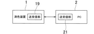
- FIG. 13 is a configuration diagram when the calculation of correction coefficients is performed by a data processing device.
- 4 is a flowchart showing a main measurement procedure executed by the color measuring device.
- 11 is a graph for explaining the influence of retro-illumination characteristics. 1 is a graph showing the effect of the present invention for a number of samples with different brightnesses. 11 is another graph showing the effect of the present invention for a number of samples with different brightnesses. 1 is a graph for explaining a problem with the conventional technology.
- FIG. 1 is a diagram showing a schematic configuration of a color measuring device 1 consisting of a spectrophotometer according to one embodiment of the present invention.
- the color measuring device 1 measures the spectral reflectance characteristics of a measuring object 100 having a two-dimensional structure such as a texture.
- the color measuring device 1 includes an integrating sphere 11, a light source 12, a light receiving unit 13, a calculation unit 14, a control unit 15, a recording unit 16, a display unit 17, and an operation panel unit 18.
- Integrating sphere 11 is a hollow sphere whose inner wall 111 is coated with a white diffuse reflective paint that has high diffusivity and high reflectance, such as magnesium oxide or barium sulfate. Integrating sphere 11 is configured to generate diffuse light by multiple reflection of light output from light source 12 on inner wall 111.
- Light source 12 is, for example, a xenon flash lamp.
- the integrating sphere 11 also has a measurement opening 112 formed at its bottom end, through which the measurement object 100 is viewed.
- the integrating sphere 11 also has a light receiving opening 114, which is located opposite the measurement opening 112 and is drilled in a direction inclined at 8° with respect to a normal 113 to the opening surface of the measurement opening 112.
- Light shielding walls 115, 115 are formed inside the integrating sphere 11 so that the light beam output from the light source 12 does not directly irradiate the measurement opening 111 and the light receiving opening 114.
- a part of the inner wall 111 of the integrating sphere 11 serves as a reference area 116 for measuring the reference light.
- the light receiving unit 13 includes a spectroscopic unit 131, an imaging lens 132, and an area sensor 133, which is a two-dimensional imaging element such as a CCD sensor.
- the spectroscopic unit 131 separates the light received through the light receiving opening 114 into separate wavelengths.
- the imaging lens 132 forms an image of the light of each wavelength separated by the spectroscopic unit 131 onto the area sensor 133.
- the area sensor 133 corresponds to a photoelectric conversion unit, and has a plurality of pixels 134 arranged vertically and horizontally as shown in FIG. 2.
- the horizontal direction of the area sensor 133 (x direction in FIG. 2) means the horizontal direction of the physical space.
- Each pixel 134 in the horizontal direction corresponds to a horizontal area of the object to be measured.
- the vertical direction of the area sensor 133 (y direction in FIG. 2) corresponds to the wavelength of light.
- each pixel 134 in the horizontal pixel row corresponds to a plurality of areas in the one-dimensional direction of the object to be measured 100, and light emitted from each area and decomposed into wavelengths is received by each pixel 134 in the vertical pixel row.
- the color measurement device may be moved in the y direction in FIG. 2, or both the object to be measured 100 and the color measurement device 1 may be moved with a speed difference.
- the measurement data which is an electrical signal output from each pixel 134 of the area sensor 133, is converted to a digital signal as necessary through a current-to-voltage (IV) conversion circuit and an analog-to-digital (AD) conversion circuit (not shown), and is sent to the calculation unit 14.
- IV current-to-voltage
- AD analog-to-digital
- the calculation unit 14 uses the measurement data sent to it to calculate the color and reflectance for each of the multiple areas on the measurement object 100. In this embodiment, the calculation unit 14 also calculates an unevenness correction coefficient and a retro-illumination correction coefficient during measurement. Furthermore, the calculation unit 14 corrects the measurement data using the calculated unevenness correction coefficient and retro-illumination correction coefficient to obtain an output value.
- the unevenness correction coefficient and retro-illumination correction coefficient will be described later.
- the control unit 15 controls the entire color measurement device 1 and includes a CPU, RAM, etc.
- the calculation unit 14 is also configured as part of the function of the control unit 15.
- the recording unit 16 is a memory that records the calculated unevenness correction coefficients and retro-illumination correction coefficients, the measurement values (output values) corrected using these correction coefficients, the measurement values before correction (raw data), etc.
- the display unit 17 displays the results of calculations performed by the calculation unit 6, other data, messages, etc.
- the operation panel unit 18 is operated by the user when using the color measurement device 1.
- the calculation unit 6 may be incorporated in the color measurement device 1 as in this embodiment.
- the calculation unit 6 may be configured by a personal computer (corresponding to a data processing device, hereinafter referred to as PC) 2 connected to the color measurement device 1, as shown in FIG. 3.
- PC data processing device
- the measurement value output from the area sensor 133 and processed into a digital signal may be sent from the transmission/reception unit 19 of the color measurement device 1 to the transmission/reception unit 21 of the PC 2 via a network and imported into the PC 2.
- the calculation results, etc. may also be recorded in a recording unit within the PC 2, or displayed on the display unit of the PC 2. With this configuration, measurements can be performed even if the PC 2 is located away from the measurement site.
- FIG. 4 is a flowchart showing the main measurement procedures executed by the colorimetric device 1.
- the procedures are executed in the following order: A/D count value acquisition process (#1), light intensity correction process (#2), unevenness correction process (#3), level calibration process (#4), retroillumination correction process (#5), and reflectance output process (#6).
- the A/D count value acquisition process (#1) is a process for acquiring data that is received by each pixel 134 of the area sensor 133, converted into an electrical signal, and then converted into a digital signal through an AD conversion circuit.
- the light quantity correction process (#2) is a process for correcting fluctuations in the light source 12.
- the unevenness correction process (#3) is a process for correcting the unevenness of each pixel caused by the components of the color measurement device 1, and is performed using an unevenness correction coefficient.
- the level calibration process (#4) is a process for calibrating the level of the measurement value, and also includes zero calibration.
- the retroillumination correction process (#5) is a process for correcting errors for each pixel 134 of the area sensor 133 caused by the re-illumination of light by the inner surface 111 of the integrating sphere 11 of the colorimeter 1, and is performed using a retroillumination correction coefficient.
- the reflectance output process (#6) is a process for outputting the measured value after each process is performed to the display unit 17, the recording unit 16, or the like.
- the unevenness correction process (#3) will be described.
- This unevenness correction process is a correction process performed to eliminate measurement errors at each portion within the measurement surface of the measurement object 100. As described in the Background Art section, measurement errors occur due to unevenness in the components of the color measuring device 1, such as unevenness in illumination, unevenness in light reception, and unevenness in the sensitivity of the area sensor 5.
- a sample is measured that has uniform brightness across the measurement surface and a nearly uniform distribution of measured values for each wavelength.
- An example of such a first sample is a flat white plate with no irregularities on its surface.
- the first sample (white plate) is measured, and the measurement value before correction is taken as Count(x,y, ⁇ ).
- (x,y) represent the x and y coordinates on the measurement surface
- ⁇ represents the wavelength (nm).
- the x and y coordinates on the measurement surface also correspond to the coordinates of the pixel 134 of the area sensor 133.
- the target value for correction is Count target ( ⁇ ). If a target value such as a measurement value from a standard color measuring device is set, that value may be used for Count target ( ⁇ ). Alternatively, it may be set as the average value of the measurement target area such as the measurement diameter.
- Count target ( ⁇ ) is as follows:
- the unevenness correction coefficient Mura(x,y, ⁇ ) can be calculated by dividing as follows so that the measurement value Count(x,y, ⁇ ) for the second sample at each pixel 134 of the area sensor 133 and each wavelength matches the target value.
- Mura(x,y, ⁇ ) which is the mura correction coefficient for each pixel (x,y) calculated in this manner
- the corrected measurement value Count corr (x,y, ⁇ ) is corrected, for example, as follows.
- Mura(x,y, ⁇ ) the above-mentioned moving average Mura'(x,y, ⁇ ) may be used as the unevenness correction coefficient.
- the non-uniformity correction coefficient is calculated for only one pixel.
- the correction coefficients for all pixels may be calculated based on the position coordinate relationship of the known in-plane non-uniformity caused by the components of the color measuring device, and this may be used as the final correction coefficient.
- the light emitted from the illuminated surface of the object 100 undergoes repeated diffuse reflection on the inner surface 111 of the integrating sphere 11, and then retro-illumination occurs, illuminating the surface of the object 100 again.
- the light beam emitted from the light source 12 is repeatedly diffusely reflected on the inner surface 111 of the integrating sphere 11, becoming diffuse illumination light that illuminates the measurement surface of the object 100 and the reference area 116 on the inner surface of the integrating sphere 11.
- the amount and effect of this retroillumination depends on the reflectance and aperture ratio of the integrating sphere 11, and the relationship between the optical path from the object 100 (sample optical path (P1 in FIG. 1)) and the optical path from the reference area 116 (reference optical path (P2 in FIG. 1)). For this reason, even if the color measuring device 1 is the same integrating sphere type, it may differ depending on the model. Since zero calibration and white calibration are performed to calibrate the zero point and white point values, the effect of the retroillumination characteristics is known to have the characteristics of a quadratic function that is generally noticeable in intermediate colors between zero and white (see FIG. 5). In FIG. 5, the horizontal axis indicates reflectance and the vertical axis indicates reflectance error. The shape of the quadratic function changes depending on the position of the aperture 114.
- second samples that have a different brightness on the measurement surface from the first sample, have uniform brightness on each part of the measurement surface, and can be considered to have a roughly uniform distribution of measurement values for each wavelength are measured for each colorimetric device 1.
- the coefficient of an approximate quadratic function which is a retroillumination characteristic unique to the colorimetric device 1 is calculated as a retroillumination correction coefficient.
- the aforementioned quadratic function is subtracted from the measurement value to reduce the influence of the retroillumination characteristic.
- an achromatic sample such as white, gray, or black is used.
- retro-illumination is a phenomenon in which light reflected from the object 100 is repeatedly diffusely reflected inside the integrating sphere 11, and then illuminates the object 100 again. Therefore, particularly in the case of a color measuring device with a relatively large measurement diameter, the effect can vary depending on the coordinates (pixels) of the measurement surface. Also, as mentioned above, the retro-illumination characteristics depend on the relationship between the sample optical path P1 and the reference optical path P2. If the sample system and the reference system have exactly the same retro-illumination characteristics, the two will cancel each other out during the calculation process for the reflectance, etc., which is the object of measurement, and there will be no effect on the output of the color measuring device 1.
- the second sample we will use three samples, sample 2-1 (white board), sample 2-2 (gray tile), and sample 2-3 (black tile).
- the target reflectances such as the measured reflectances using the reference colorimetric device, are Rc_1( ⁇ ), Rc_2( ⁇ ), and Rc_3( ⁇ ), respectively.
- the measured reflectances of samples 2-1, 2-2, and 2-3 measured using the colorimetric device 1 to be corrected are Rs_1( ⁇ ), Rs_2( ⁇ ), and Rs_3( ⁇ ), respectively.
- the difference in the retroillumination characteristics between two different color measuring devices is an error of a quadratic function where the error is 0 at the common zero calibration point and white calibration point when the horizontal axis is the reflectance and the vertical axis is the reflectance error.
- this characteristic is unique to the device. For this reason, sample 2-1, sample 2-2, and sample 2-3, which have known target reflectances, are measured with the color measuring device 1 to be corrected, and the error amount (quadratic function) due to the retroillumination characteristics is estimated and subtracted, making correction possible.
- the following three points are defined as follows.
- the quadratic, linear, and zero-order coefficients are a2_2(x,y, ⁇ ), a2_1(x,y, ⁇ ), If we define a2_0(x, y, ⁇ ), there are three types of undetermined coefficients and three passing points, so the exact solution can be found as follows.
- a2_2(x,y, ⁇ ) ((Y1-Y2)*(X1-X3)-(Y1-Y3)*(X1-X2))/((X1-X2)*(X1-X3)*(X2 -X3))
- a2_1(x,y, ⁇ ) (Y1-Y2)/(X1-X2)-(a2_2)*(X1+X2)
- a2_0(x,y, ⁇ ) Y1-(a2_2)*X1*X1-(a2_1)*X1
- One method is to calculate a moving average over multiple pixels adjacent to a pixel. The following is an example of a correction coefficient when calculating a moving average over ⁇ 5 pixels adjacent to the pixel to be calculated.
- the measured values of the measurement object 100 are corrected (retro-illumination correction) using the retro-illumination correction coefficients a2_2(x,y, ⁇ ), a2_1(x,y, ⁇ ), and a2_0(x,y, ⁇ ) calculated in this way, which are specific to the pixel (x,y), to remove the effects of the retro-illumination characteristics of the color measuring device 1.
- the retroreflighting characteristics can be approximated by a quadratic function and can be corrected, for example, as follows:
- a2_2'(x,y, ⁇ ), a2_1'(x,y, ⁇ ), and a2_0'(x,y, ⁇ ) after moving average may be used as the retro-illumination correction coefficient.
- the retroreflection correction coefficients a2_2(x,y, ⁇ ), a2_1(x,y, ⁇ ), and a2_0(x,y, ⁇ ) of each pixel are continuous functions, and may be approximated by polynomials such as quadratic functions.
- the correction coefficient for only one pixel is calculated, the correction coefficients for the remaining pixels can be calculated from the position coordinates of the measurement surface, and these can be used as the final correction coefficients.
- Fig. 6 shows the effect of correction, and is a graph showing the characteristics when unevenness correction and retro-illumination correction are performed.
- the graph in Fig. 6 corresponds to Fig. 8(a)(b), and the vertical and horizontal axes are the same as Fig. 8(a)(b).
- S1 is a calibration white plate
- S2 to S5 are achromatic reference samples with different brightness levels, which are also the same as Fig. 8(a)(b).
- FIG. 7 is a graph showing the variation (standard deviation) of the measured values when each part of the measurement surface is measured by the colorimeter 1 using the SCI method in each of the cases of no correction, only unevenness correction, and both unevenness correction and retro-illumination correction for each of the samples S1 to S5.
- the four bar graphs for each sample represent, from the left, ⁇ L * , ⁇ a * , ⁇ b * , and ⁇ dE, respectively.
- the present invention is not limited to the above embodiment.
- both unevenness correction and retro-illumination correction have been performed, only retro-illumination correction may be performed.
- unevenness correction coefficient and retro-illumination correction coefficient were calculated for each wavelength, but they may also be calculated for each tristimulus value XYZ.
- the measurement was performed based on the diffuse reflected light from the light source 12, it may be performed by measuring the transmitted light.
- the present invention can be used as a color measuring device to measure the color, reflectance, etc. of an object.
- Color measuring device 2 Personal computer (data processing device) 11 Integrating sphere (lighting part) 12 Light source (lighting section) 13 light receiving unit 14 calculation unit 15 control unit 16 recording unit, 17 Display section 18 Operation panel section 19 Transmitting/receiving section 21 Transmitting/receiving section 100 Measurement object 111 Inner surface 112 Measurement aperture 113 Normal line 114 Light receiving aperture 115 Light shielding plate 131 Spectroscopic section 132 Imaging lens 133 Area sensor (photoelectric conversion section) 134 pixels
Landscapes
- Physics & Mathematics (AREA)
- Spectroscopy & Molecular Physics (AREA)
- General Physics & Mathematics (AREA)
- Spectrometry And Color Measurement (AREA)
Priority Applications (3)
| Application Number | Priority Date | Filing Date | Title |
|---|---|---|---|
| CN202480015294.7A CN120787307A (zh) | 2023-02-28 | 2024-02-07 | 测色装置、数据处理装置、测量校正方法以及程序 |
| EP24763554.3A EP4675242A1 (en) | 2023-02-28 | 2024-02-07 | Color measurement device, data processing device, measurement correction method, and program |
| JP2025503716A JPWO2024181070A1 (https=) | 2023-02-28 | 2024-02-07 |
Applications Claiming Priority (2)
| Application Number | Priority Date | Filing Date | Title |
|---|---|---|---|
| JP2023029998 | 2023-02-28 | ||
| JP2023-029998 | 2023-02-28 |
Publications (1)
| Publication Number | Publication Date |
|---|---|
| WO2024181070A1 true WO2024181070A1 (ja) | 2024-09-06 |
Family
ID=92589637
Family Applications (1)
| Application Number | Title | Priority Date | Filing Date |
|---|---|---|---|
| PCT/JP2024/004135 Ceased WO2024181070A1 (ja) | 2023-02-28 | 2024-02-07 | 測色装置、データ処理装置、測定補正方法及びプログラム |
Country Status (4)
| Country | Link |
|---|---|
| EP (1) | EP4675242A1 (https=) |
| JP (1) | JPWO2024181070A1 (https=) |
| CN (1) | CN120787307A (https=) |
| WO (1) | WO2024181070A1 (https=) |
Citations (7)
| Publication number | Priority date | Publication date | Assignee | Title |
|---|---|---|---|---|
| JPH1172388A (ja) * | 1997-08-28 | 1999-03-16 | Minolta Co Ltd | 反射特性測定装置 |
| JP2015178995A (ja) * | 2014-03-19 | 2015-10-08 | 株式会社オプトコム | 色調校正装置、撮像装置及び色調検査装置 |
| CN105424186A (zh) * | 2015-11-04 | 2016-03-23 | 北京航空航天大学 | 一种光场成像光谱仪的光谱标定校正方法 |
| JP2017036937A (ja) * | 2015-08-07 | 2017-02-16 | コニカミノルタ株式会社 | 測色装置、測色システム、および測色方法 |
| US9784614B2 (en) | 2015-02-09 | 2017-10-10 | Datacolor Holding Ag | Method and apparatus for color measurement of non-solid colors |
| JP2021135102A (ja) * | 2020-02-25 | 2021-09-13 | 株式会社パパラボ | 色・質感測定装置及び方法 |
| JP2023029998A (ja) | 2018-12-27 | 2023-03-07 | 株式会社日本触媒 | 新規エマルション及びこのエマルションを用いた塗料用組成物 |
-
2024
- 2024-02-07 WO PCT/JP2024/004135 patent/WO2024181070A1/ja not_active Ceased
- 2024-02-07 CN CN202480015294.7A patent/CN120787307A/zh active Pending
- 2024-02-07 EP EP24763554.3A patent/EP4675242A1/en active Pending
- 2024-02-07 JP JP2025503716A patent/JPWO2024181070A1/ja active Pending
Patent Citations (7)
| Publication number | Priority date | Publication date | Assignee | Title |
|---|---|---|---|---|
| JPH1172388A (ja) * | 1997-08-28 | 1999-03-16 | Minolta Co Ltd | 反射特性測定装置 |
| JP2015178995A (ja) * | 2014-03-19 | 2015-10-08 | 株式会社オプトコム | 色調校正装置、撮像装置及び色調検査装置 |
| US9784614B2 (en) | 2015-02-09 | 2017-10-10 | Datacolor Holding Ag | Method and apparatus for color measurement of non-solid colors |
| JP2017036937A (ja) * | 2015-08-07 | 2017-02-16 | コニカミノルタ株式会社 | 測色装置、測色システム、および測色方法 |
| CN105424186A (zh) * | 2015-11-04 | 2016-03-23 | 北京航空航天大学 | 一种光场成像光谱仪的光谱标定校正方法 |
| JP2023029998A (ja) | 2018-12-27 | 2023-03-07 | 株式会社日本触媒 | 新規エマルション及びこのエマルションを用いた塗料用組成物 |
| JP2021135102A (ja) * | 2020-02-25 | 2021-09-13 | 株式会社パパラボ | 色・質感測定装置及び方法 |
Non-Patent Citations (1)
| Title |
|---|
| See also references of EP4675242A1 |
Also Published As
| Publication number | Publication date |
|---|---|
| CN120787307A (zh) | 2025-10-14 |
| JPWO2024181070A1 (https=) | 2024-09-06 |
| EP4675242A1 (en) | 2026-01-07 |
Similar Documents
| Publication | Publication Date | Title |
|---|---|---|
| JP5475057B2 (ja) | 変角分光イメージング測定方法およびその装置 | |
| US8988682B2 (en) | High accuracy imaging colorimeter by special designed pattern closed-loop calibration assisted by spectrograph | |
| JP5412694B2 (ja) | 光源測定法および光源測定システム | |
| JP4660694B2 (ja) | 分光装置の波長校正方法及び分光装置 | |
| JP7687559B2 (ja) | 撮像システム | |
| JP2002303548A (ja) | 平坦な測定対象物の光電測定用装置 | |
| Stokman et al. | Color measurement by imaging spectrometry | |
| JP2015178995A (ja) | 色調校正装置、撮像装置及び色調検査装置 | |
| JP5918993B2 (ja) | 高彩度色光生成装置及び色再現評価方法 | |
| JP2010139324A (ja) | 色ムラ測定方法、および色ムラ測定装置 | |
| WO2016181746A1 (ja) | 分光測色装置、および分光反射率の算出方法 | |
| WO2024181070A1 (ja) | 測色装置、データ処理装置、測定補正方法及びプログラム | |
| JP7428090B2 (ja) | 校正装置、校正方法、校正プログラム、及び分光カメラ | |
| JP6919339B2 (ja) | 二次元測色装置 | |
| JP2010203825A (ja) | モニタの分光分布測定方法 | |
| JP2007093477A (ja) | 色測定装置の校正方法および校正装置、色測定方法、色測定装置 | |
| US11985299B2 (en) | Calibration device, calibration method, calibration program, spectroscopic camera, and information processing device | |
| WO2020003673A1 (ja) | イメージセンサの分光感度測定方法、分光感度測定装置の検査方法及び分光感度測定装置 | |
| Zhu et al. | Color calibration for colorized vision system with digital sensor and LED array illuminator | |
| JP7779022B2 (ja) | 分光計測器、及びコンピュータープログラム | |
| TWI385363B (zh) | 建構光源量測對照表之方法、光源量測方法及光源量測系統 | |
| JP6683201B2 (ja) | 分光測色装置、および変換ルール設定方法 | |
| JP7552142B2 (ja) | 情報処理装置およびプログラム | |
| JP2001318001A (ja) | 色彩測定装置 | |
| JPH09214786A (ja) | 画像処理装置及び方法 |
Legal Events
| Date | Code | Title | Description |
|---|---|---|---|
| 121 | Ep: the epo has been informed by wipo that ep was designated in this application |
Ref document number: 24763554 Country of ref document: EP Kind code of ref document: A1 |
|
| WWE | Wipo information: entry into national phase |
Ref document number: 2025503716 Country of ref document: JP |
|
| WWE | Wipo information: entry into national phase |
Ref document number: 202480015294.7 Country of ref document: CN |
|
| WWE | Wipo information: entry into national phase |
Ref document number: 2024763554 Country of ref document: EP |
|
| NENP | Non-entry into the national phase |
Ref country code: DE |
|
| WWP | Wipo information: published in national office |
Ref document number: 202480015294.7 Country of ref document: CN |
|
| ENP | Entry into the national phase |
Ref document number: 2024763554 Country of ref document: EP Effective date: 20250929 |
|
| ENP | Entry into the national phase |
Ref document number: 2024763554 Country of ref document: EP Effective date: 20250929 |
|
| ENP | Entry into the national phase |
Ref document number: 2024763554 Country of ref document: EP Effective date: 20250929 |
|
| WWP | Wipo information: published in national office |
Ref document number: 2024763554 Country of ref document: EP |