WO2024181016A1 - 超硬合金、被覆工具及び切削工具 - Google Patents
超硬合金、被覆工具及び切削工具 Download PDFInfo
- Publication number
- WO2024181016A1 WO2024181016A1 PCT/JP2024/003397 JP2024003397W WO2024181016A1 WO 2024181016 A1 WO2024181016 A1 WO 2024181016A1 JP 2024003397 W JP2024003397 W JP 2024003397W WO 2024181016 A1 WO2024181016 A1 WO 2024181016A1
- Authority
- WO
- WIPO (PCT)
- Prior art keywords
- cemented carbide
- layer
- region
- average
- coated tool
- Prior art date
- Legal status (The legal status is an assumption and is not a legal conclusion. Google has not performed a legal analysis and makes no representation as to the accuracy of the status listed.)
- Ceased
Links
Images


Classifications
-
- B—PERFORMING OPERATIONS; TRANSPORTING
- B22—CASTING; POWDER METALLURGY
- B22F—WORKING METALLIC POWDER; MANUFACTURE OF ARTICLES FROM METALLIC POWDER; MAKING METALLIC POWDER; APPARATUS OR DEVICES SPECIALLY ADAPTED FOR METALLIC POWDER
- B22F3/00—Manufacture of workpieces or articles from metallic powder characterised by the manner of compacting or sintering; Apparatus specially adapted therefor ; Presses and furnaces
- B22F3/24—After-treatment of workpieces or articles
-
- B—PERFORMING OPERATIONS; TRANSPORTING
- B22—CASTING; POWDER METALLURGY
- B22F—WORKING METALLIC POWDER; MANUFACTURE OF ARTICLES FROM METALLIC POWDER; MAKING METALLIC POWDER; APPARATUS OR DEVICES SPECIALLY ADAPTED FOR METALLIC POWDER
- B22F7/00—Manufacture of composite layers, workpieces, or articles, comprising metallic powder, by sintering the powder, with or without compacting wherein at least one part is obtained by sintering or compression
-
- B—PERFORMING OPERATIONS; TRANSPORTING
- B23—MACHINE TOOLS; METAL-WORKING NOT OTHERWISE PROVIDED FOR
- B23B—TURNING; BORING
- B23B27/00—Tools for turning or boring machines; Tools of a similar kind in general; Accessories therefor
- B23B27/14—Cutting tools of which the bits or tips or cutting inserts are of special material
-
- C—CHEMISTRY; METALLURGY
- C04—CEMENTS; CONCRETE; ARTIFICIAL STONE; CERAMICS; REFRACTORIES
- C04B—LIME, MAGNESIA; SLAG; CEMENTS; COMPOSITIONS THEREOF, e.g. MORTARS, CONCRETE OR LIKE BUILDING MATERIALS; ARTIFICIAL STONE; CERAMICS; REFRACTORIES; TREATMENT OF NATURAL STONE
- C04B35/00—Shaped ceramic products characterised by their composition; Ceramics compositions; Processing powders of inorganic compounds preparatory to the manufacturing of ceramic products
- C04B35/515—Shaped ceramic products characterised by their composition; Ceramics compositions; Processing powders of inorganic compounds preparatory to the manufacturing of ceramic products based on non-oxide ceramics
- C04B35/56—Shaped ceramic products characterised by their composition; Ceramics compositions; Processing powders of inorganic compounds preparatory to the manufacturing of ceramic products based on non-oxide ceramics based on carbides or oxycarbides
-
- C—CHEMISTRY; METALLURGY
- C04—CEMENTS; CONCRETE; ARTIFICIAL STONE; CERAMICS; REFRACTORIES
- C04B—LIME, MAGNESIA; SLAG; CEMENTS; COMPOSITIONS THEREOF, e.g. MORTARS, CONCRETE OR LIKE BUILDING MATERIALS; ARTIFICIAL STONE; CERAMICS; REFRACTORIES; TREATMENT OF NATURAL STONE
- C04B41/00—After-treatment of mortars, concrete, artificial stone or ceramics; Treatment of natural stone
- C04B41/80—After-treatment of mortars, concrete, artificial stone or ceramics; Treatment of natural stone of only ceramics
- C04B41/81—Coating or impregnation
- C04B41/89—Coating or impregnation for obtaining at least two superposed coatings having different compositions
-
- C—CHEMISTRY; METALLURGY
- C22—METALLURGY; FERROUS OR NON-FERROUS ALLOYS; TREATMENT OF ALLOYS OR NON-FERROUS METALS
- C22C—ALLOYS
- C22C1/00—Making non-ferrous alloys
- C22C1/04—Making non-ferrous alloys by powder metallurgy
- C22C1/05—Mixtures of metal powder with non-metallic powder
- C22C1/051—Making hard metals based on borides, carbides, nitrides, oxides or silicides; Preparation of the powder mixture used as the starting material therefor
-
- C—CHEMISTRY; METALLURGY
- C22—METALLURGY; FERROUS OR NON-FERROUS ALLOYS; TREATMENT OF ALLOYS OR NON-FERROUS METALS
- C22C—ALLOYS
- C22C1/00—Making non-ferrous alloys
- C22C1/10—Alloys containing non-metals
-
- C—CHEMISTRY; METALLURGY
- C22—METALLURGY; FERROUS OR NON-FERROUS ALLOYS; TREATMENT OF ALLOYS OR NON-FERROUS METALS
- C22C—ALLOYS
- C22C29/00—Alloys based on carbides, oxides, nitrides, borides, or silicides, e.g. cermets, or other metal compounds, e.g. oxynitrides, sulfides
- C22C29/02—Alloys based on carbides, oxides, nitrides, borides, or silicides, e.g. cermets, or other metal compounds, e.g. oxynitrides, sulfides based on carbides or carbonitrides
Definitions
- This disclosure relates to cemented carbide, coated tools and cutting tools.
- Cemented carbide containing WC (tungsten carbide) is used as the substrate for coated tools and is used in cutting tools. Such cemented carbide is required to have chipping resistance.
- the cemented carbide (WC-based cemented carbide substrate) described in JP 2022-532 A (Patent Document 1) is known as an example of a cemented carbide with excellent chipping resistance.
- the cemented carbide described in Patent Document 1 has a layered region that does not have a ⁇ phase from the surface toward the inside. The difference between the minimum Vickers hardness in this region and the Vickers hardness in the interior 300 ⁇ m away from the surface is 180 to 230 Hv.
- a non-limiting aspect of the present disclosure is a cemented carbide having a hard phase containing W and C, a solid solution phase containing W, C, and Ti, and a binder phase containing an iron group metal.
- the cemented carbide has a surface region that exists from the surface of the cemented carbide toward the inside, and an internal region that exists from the surface region toward the inside. The difference between the average Vickers hardness in the surface region and the average Vickers hardness in the internal region is 1 to 100 Hv.
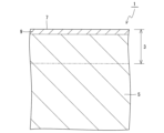
- FIG. 2 is a cross-sectional view showing the vicinity of the surface of one non-limiting surface of a cemented carbide according to the present disclosure.
- FIG. 1 is a perspective view of a non-limiting one-sided coated tool of the present disclosure.
- FIG. 2 is a cross-sectional view showing the vicinity of a surface of a non-limiting one-sided coated tool of the present disclosure.
- FIG. 2 is a cross-sectional view showing the vicinity of a surface of a non-limiting one-sided coated tool of the present disclosure.
- FIG. 1 is a perspective view of a non-limiting one-sided cutting tool of the present disclosure.
- cemented carbide 1 according to one aspect of the present disclosure will be described in detail with reference to the drawings.
- the cemented carbide 1 may include any component member not shown in each of the drawings referred to.
- the dimensions of the components in each drawing do not faithfully represent the actual dimensions of the components and the dimensional ratios of each component.
- the cemented carbide 1 may have a hard phase, a solid solution phase, and a binder phase.
- the hard phase may contain W (tungsten) and C (carbon).
- the hard phase may contain W and C as the main components.
- "Main component” may mean the component with the largest mass% value compared to other components. Specifically, the top two mass% values of the components contained in the hard phase may be W and C.
- the hard phase may contain W and C in the form of WC.
- the solid solution phase may contain W, C, and Ti (titanium).
- the solid solution phase may contain W, C, and Ti as the main components. That is, the total mass percentage of W, C, and Ti may be the largest in the solid solution phase. Also, the top three mass percentage values of the components contained in the solid solution phase may be W, C, and Ti.
- the binder phase may contain an iron group metal.
- iron group metals include Co (cobalt) and Ni (nickel).
- the binder phase may contain at least one of Co and Ni.
- the binder phase may contain an iron group metal as a main component. Iron group metals, including Co and Ni as examples, may have the largest mass percentage of the components contained in the binder phase.
- the binder phase may function as a phase that bonds adjacent hard phases.
- compositions of the hard phase, solid solution phase, and bonding phase may be measured, for example, by Energy Dispersive X-ray Spectroscopy (EDS).
- EDS Energy Dispersive X-ray Spectroscopy
- the measurements may be performed using an EDS attached to an electron microscope.
- electron microscopes include a Scanning Electron Microscopy (SEM) and a Transmission Electron Microscopy (TEM).
- the cemented carbide 1 may have a surface region 3 and an internal region 5, as shown in a non-limiting example in FIG. 1.
- the surface region 3 may exist from the surface 7 of the cemented carbide 1 toward the inside.
- the internal region 5 may exist from the surface region 3 toward the inside.
- the Vickers hardness (Hv) in the surface region 3 and the internal region 5 may have the following relationship.
- the difference between the average Vickers hardness in the surface region 3 and the average Vickers hardness in the internal region 5 may be 1 to 100 Hv.
- the value calculated from the formula: (average Vickers hardness in the surface region) - (average Vickers hardness in the internal region) may be 1 to 100 Hv.
- the difference in hardness between the surface region 3 and the internal region 5 is relatively small. And because this difference is positive, the surface region 3 is slightly harder than the internal region 5, and wear resistance is likely to be improved. Also, because the internal region 5 is relatively slightly softer, the impact that occurs between the surface region 3 and the workpiece during cutting is likely to be mitigated by the internal region 5, and chipping resistance is also likely to be improved. Therefore, the cemented carbide 1 has high wear resistance and chipping resistance. The cemented carbide 1 can achieve both high wear resistance and high chipping resistance.
- the difference may be 30 to 100 Hv. In this case, wear resistance and chipping resistance are likely to be improved.
- the lower limit of the difference may be, for example, 5 Hv.
- the upper limit of the difference may be, for example, 40 Hv.
- the average Vickers hardness in the surface region 3 may be 1350 to 1700 Hv.
- the average Vickers hardness in the surface region 3 may be 1350 to 1550 Hv.
- the maximum value of the Vickers hardness in the entire surface region 3 and the internal region 5 may be located in the surface region 3.
- the average Vickers hardness in the inner region 5 may be 1300 to 1650 Hv.
- the average Vickers hardness in the inner region 5 may be 1300 to 1500 Hv.
- the minimum value of the Vickers hardness in the entire surface region 3 and inner region 5 may be located in the inner region 5.
- the average Vickers hardness may be a value measured in accordance with JIS Z 2244: 2009. Specific measurement conditions for the average Vickers hardness may be set, for example, as follows.
- Measuring device INNOVATEST Push-in strength: 10kgf Atmosphere: Air Measurement temperature: 25°C Number of measurements: 3 Other: The cemented carbide is polished at an angle (3° inclination) from the surface to form a polished surface, which is used as the measurement surface. The polishing is performed using diamond paste.
- the surface region 3 may include the surface 7 of the cemented carbide 1.
- the internal region 5 may also be in contact with the surface region 3.
- the thickness of the surface region 3 may be smaller than the thickness of the internal region 5.
- the thickness of the surface region 3 may be 1/10 or less of the thickness of the internal region 5.
- the thickness of the surface region 3 may be 2 to 20 ⁇ m.
- the thickness of the internal region 5 may be 50 to 150 ⁇ m.
- the thicknesses of the surface region 3 and the internal region 5 may be measured by cross-sectional observation using an electron microscope.
- the cemented carbide 1 may have a de- ⁇ layer 9 on the surface 7, which is made only of WC and iron-group metals.
- the de- ⁇ layer 9 is rich in iron-group metals such as Co and is a tough layer that can function as a layer that absorbs the impact that occurs between the workpiece during cutting and suppresses chipping.
- the de- ⁇ layer 9 consisting only of WC and iron group metals may mean that almost all of the components constituting the de- ⁇ layer 9 are WC and iron group metals. Therefore, the de- ⁇ layer 9 may contain impurities at a level that is unavoidable in the manufacturing process.
- the total content of impurities may be 3 mass% or less. In other words, the total value of WC and iron group metals may be 97 mass% or more.
- the iron group metal in the de- ⁇ layer 9 may have the same composition as the iron group metal in the binder phase.
- the de- ⁇ layer 9 may be confirmed, for example, by EDS.
- the surface region 3 may include a de- ⁇ layer 9. That is, the surface region 3 may include a de- ⁇ layer 9 in addition to the hard phase, solid solution phase, and bonding phase. In this case, the surface region 3 is likely to be a region with a higher amount of iron group metals than the internal region 5.
- the total thickness of the surface region 3 including the de- ⁇ layer 9 may be greater than the thickness of the de- ⁇ layer 9.
- the thickness of the de- ⁇ layer 9 is not limited to a specific thickness.
- the thickness of the de- ⁇ layer 9 may be 1 to 19 ⁇ m.
- the thickness of the de- ⁇ layer 9 may be measured by cross-sectional observation using an electron microscope.
- the thickness of the de- ⁇ layer 9 may also be an average value. For example, the thickness may be measured at 10 or more measurement points at any position of the de- ⁇ layer 9, and the average value may be calculated.
- the iron group metal may be Co. Furthermore, the difference between the average Co amount in the surface region 3 and the average Co amount in the internal region 5 may be -0.1 to -3 mass%. In other words, the value calculated from the formula: (average Co amount in the surface region) - (average Co amount in the internal region) may be -0.1 to -3 mass%. In this case, wear resistance and chipping resistance are likely to be improved.
- the total thickness of the surface region 3 is greater than the thickness of the de- ⁇ layer 9, and the thickness of the de- ⁇ layer 9 is 1 to 15 ⁇ m
- the difference between the average Co content in the surface region 3 and the average Co content in the internal region 5 is likely to be -0.1 to -3 mass%.
- the average Co content in the surface region 3 may be 5 to 10 mass%.
- the average Co content in the internal region 5 may be 6 to 12 mass%.
- the average Co content may be the average value of five measurements using EDS. For example, when the surface region 3 is 20 ⁇ m, the measurement points may be 3, 7, 11, 15, and 19 ⁇ m from the surface 7, and the average value measured at these five points may be used.
- WC powder, Co powder, TiC powder, etc. may be prepared as raw material powders.
- the proportion of Co powder may be 5 to 12 mass %.
- the proportion of TiC powder may be 0.5 to 15 mass %.
- the remainder may be WC powder.
- NbC powder, TaC powder, and ZrC powder may be further prepared as raw material powders. The presence of these raw material powders tends to result in a relatively high average Vickers hardness in the surface region.
- the proportion of NbC powder may be 0.1 to 15 mass%.
- the proportion of TaC powder may be 0.1 to 15 mass%.
- the proportion of ZrC powder may be 0.1 to 15 mass%.
- TiN powder may be further prepared as a raw material powder.
- the proportion of TiN powder may be 0 to 0.5 mass%.
- the average particle size of the raw material powder may be appropriately selected in the range of 0.1 to 10 ⁇ m.
- the average particle size of the raw material powder may be a value measured by the Microtrack method.
- the prepared raw material powders may be mixed and molded to obtain a molded body.
- molding methods include press molding, casting, extrusion molding, and cold isostatic pressing.
- the obtained molded body may be subjected to a binder removal process and then fired. Firing may be performed in a non-oxidizing atmosphere such as a vacuum, argon atmosphere, or nitrogen atmosphere.
- the firing temperature may be 1450 to 1650°C.
- a high firing temperature of 1500 to 1650°C tends to result in a relatively high average Vickers hardness in the surface region. From the same perspective, the firing temperature may be set to 1550 to 1650°C.
- the firing time may be 0.5 to 3 hours.
- the material After firing, the material may be cooled to obtain a cemented carbide alloy.
- cemented carbide is not limited to those manufactured by the above manufacturing method.
- the coated tool 101 may have a cemented carbide 1 and a coating layer 103 located on the surface 7 of the cemented carbide 1, as in the non-limiting example shown in Figures 2 to 4.
- the coated tool 101 may have a cemented carbide 1 as a substrate.
- the wear resistance and chipping resistance of the cemented carbide 1 are high, so that cutting performance such as intermittent performance is likely to be improved. Therefore, the durability of the coated tool 101 is high.
- the coating layer 103 may be located on the entire surface 7 of the cemented carbide 1, or may be located on only a portion of the surface. In other words, the coating layer 103 may be located on at least a portion of the surface 7 of the cemented carbide 1.
- the coating layer 103 may be formed by a chemical vapor deposition (CVD) method.
- the coating layer 103 may be a CVD film.
- the coating layer 103 may also be a physical vapor deposition (PVD) film formed by a PVD method.
- the coating layer 103 may be a single layer or a laminate of multiple layers.
- Examples of the composition of the coating layer 103 include TiCN (titanium carbonitride), Al2O3 ( alumina), and TiN (titanium nitride).
- the coating layer 103 may have, in order from the cemented carbide 1 side, a TiCN layer 105 and an Al2O3 layer 107, as in a non-limiting example shown in Figure 3.
- the TiCN layer 105 may be in contact with the cemented carbide 1.
- the Al2O3 layer 107 may be in contact with the TiCN layer 105.
- the coating layer 103 may have a TiN layer 109, a TiCN layer 105, and an Al2O3 layer 107, in that order from the cemented carbide 1.
- the TiN layer 109 may be in contact with the cemented carbide 1.
- the TiCN layer 105 may be in contact with the TiN layer 109.
- the Al2O3 layer 107 may be in contact with the TiCN layer 105.
- the coating layer 103 is not limited to a specific thickness.
- the TiCN layer 105 may have an average thickness of about 1 to 15 ⁇ m.
- the Al 2 O 3 layer 107 may have an average thickness of about 1 to 15 ⁇ m.
- the TiN layer 109 may have an average thickness of about 0.1 to 5 ⁇ m.
- the thickness of the coating layer 103 may be measured by cross-sectional observation using an electron microscope. For example, the thickness may be measured at 10 or more measurement points at any position of each layer, and the average value may be calculated.
- a cutting insert is shown as a non-limiting example of the coated tool 101. Note that the form of the coated tool 101 is not limited to a cutting insert.
- the coated tool 101 may have a first surface 111 (top surface), a second surface 113 (side surface) adjacent to the first surface 111, and a cutting edge 115 located at the intersection of the first surface 111 and the second surface 113.
- the first surface 111 may be a rake surface.
- the first surface 111 may be a rake surface in its entirety, or only a portion of the first surface 111 may be a rake surface.
- the area of the first surface 111 along the cutting edge 115 may be a rake surface.
- the second surface 113 may be a flank surface.
- the second surface 113 may be a flank surface entirely, or only a portion of the second surface 113 may be a flank surface.
- the area of the second surface 113 along the cutting edge 115 may be a flank surface.
- the cutting edge 115 may be located over the entire intersection of the first surface 111 and the second surface 113, or may be located over only a portion of this intersection.
- the cutting edge 115 can be used to cut a workpiece when manufacturing a machined product using the coated tool 101.
- the coated tool 101 may have a through hole 117.
- the through hole 117 can be used to attach a screw or a clamp member when fixing the coated tool 101 to a holder.
- the through hole 117 may be formed from the first surface 111 to the surface (lower surface) located opposite the first surface 111, and may open in these surfaces. Note that there is no problem even if the through holes 117 are configured to open in opposing areas of the second surface 113.
- the coated tool 101 may have a rectangular plate shape. Note that the shape of the coated tool 101 is not limited to a rectangular plate shape.
- the first surface 111 may have a triangular, pentagonal, hexagonal, or circular shape.
- the coated tool 101 is not limited to a specific size.
- the length of one side of the first surface 111 may be set to approximately 3 to 20 mm.
- the height from the first surface 111 to the surface (lower surface) located on the opposite side of the first surface 111 may be set to approximately 5 to 20 mm.
- a coating layer may be formed on the surface of the cemented carbide alloy by the CVD method to obtain a coated tool.
- the TiCN layer may be formed as follows. First, a mixed gas containing 0.1 to 10 volume % titanium tetrachloride (TiCl 4 ) gas, 10 to 60 volume % nitrogen (N 2 ) gas, 0.1 to 15 volume % methane (CH 4 ) gas, and the remainder hydrogen (H 2 ) gas may be prepared as the reaction gas composition. Then, this mixed gas may be introduced into a chamber, and the temperature may be set to 800 to 1100° C. and the pressure may be set to 5 to 30 kPa to form the TiCN layer.
- TiCl 4 titanium tetrachloride
- N 2 nitrogen
- CH 4 0.1 to 15 volume % methane
- H 2 hydrogen
- the Al 2 O 3 layer may be formed as follows. First, a mixed gas may be prepared as a reaction gas composition, which is 0.5 to 5 volume % aluminum trichloride (AlCl 3 ) gas, 0.5 to 3.5 volume % hydrogen chloride (HCl) gas, 0.5 to 5 volume % carbon dioxide (CO 2 ) gas, 0.5 volume % or less hydrogen sulfide (H 2 S) gas, and the remainder hydrogen (H 2 ) gas. Then, this mixed gas may be introduced into a chamber, and the temperature may be set to 930 to 1010° C. and the pressure may be set to 5 to 10 kPa, to form the Al 2 O 3 layer.
- AlCl 3 aluminum trichloride
- HCl hydrogen chloride
- CO 2 carbon dioxide
- H 2 S hydrogen sulfide
- H 2 S hydrogen sulfide
- the TiN layer may be formed as follows. First, a mixed gas containing 0.1 to 10 volume % titanium tetrachloride (TiCl 4 ) gas, 10 to 60 volume % nitrogen (N 2 ) gas, and the remainder hydrogen (H 2 ) gas may be prepared as the reaction gas composition. Then, this mixed gas may be introduced into a chamber, and the temperature may be set to 800 to 1010° C. and the pressure may be set to 10 to 85 kPa to form the TiN layer.
- TiCl 4 titanium tetrachloride
- N 2 nitrogen
- H 2 hydrogen
- coated tools are not limited to those manufactured by the above manufacturing method.
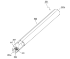
- the cutting tool 201 may include a holder 203 and a coated tool 101, as shown in a non-limiting example in FIG. 5.
- the holder 203 may extend from a first end 203a toward a second end 203b, and may have a pocket 205 on the side of the first end 203a.
- the coated tool 101 may be located in the pocket 205.
- the coated tool 101 has high durability, enabling stable cutting.
- the pocket 205 may be a portion in which the coated tool 101 is attached.
- the pocket 205 may be open on the outer peripheral surface of the holder 203 and on the end surface on the side of the first end 203a.
- the coated tool 101 may be attached to the pocket 205 so that at least a part of the cutting edge 115 protrudes from the holder 203.
- the coated tool 101 may also be attached to the pocket 205 by a screw 207. That is, the coated tool 101 may be attached to the pocket 205 by inserting the screw 207 into the through hole 117 of the coated tool 101, inserting the tip of the screw 207 into a screw hole formed in the pocket 205, and fixing the screw 207 to the screw hole. At this time, the bottom surface of the coated tool 101 may be in direct contact with the pocket 205, or a sheet may be sandwiched between the coated tool 101 and the pocket 205.
- the material of the holder 203 may be, for example, steel or cast iron. If the material of the holder 203 is steel, the holder 203 has high toughness.
- a cutting tool 201 used for so-called turning is illustrated.
- Examples of turning include internal diameter machining, external diameter machining, and groove machining.
- the cutting tool 201 (coated tool 101) is not limited to use for turning. For example, there is no problem in using the coated tool 101 as the cutting tool 201 used for turning.
- the cemented carbide 1 is used for the coated tool 101 and the cutting tool 201, but the cemented carbide 1 can also be used for other applications.
- other applications include wear-resistant parts such as sliding parts or dies, tools such as drilling tools and blades, and impact-resistant parts.
- the cemented carbide 1, the coated tool 101 and the cutting tool 201 may have the following configurations.
- the cemented carbide has a hard phase containing W and C, a solid solution phase containing W, C and Ti, and a binder phase containing an iron-group metal, and has a surface region that extends from the surface of the cemented carbide toward the inside, and an internal region that extends from the surface region toward the inside, and the difference between the average Vickers hardness in the surface region and the average Vickers hardness in the internal region is 1 to 100 Hv.
- the difference may be 30 to 100 Hv.
- the iron-group metal may be cobalt, and the difference between the average cobalt content in the surface region and the average cobalt content in the inner region may be ⁇ 0.1 to ⁇ 3 mass %.
- a coated tool may have any one of the cemented carbide alloys (1) to (3) above and a coating layer located on the surface of the cemented carbide alloy.
- the coating layer may have, from the cemented carbide side, a TiCN layer and an Al2O3 layer in this order.
- the coating layer may have, from the cemented carbide side, a TiN layer, a TiCN layer, and an Al2O3 layer in this order.
- the cutting tool may include a holder extending from a first end toward a second end and having a pocket on the side of the first end, and a coated tool according to any one of (4) to (6) above, located in the pocket.
- WC powder with an average particle size of 9 ⁇ m, Co powder with an average particle size of 1.5 ⁇ m, TiC powder with an average particle size of 1.5 ⁇ m, NbC powder with an average particle size of 1.1 ⁇ m, TaC powder with an average particle size of 0.9 ⁇ m, ZrC powder with an average particle size of 1.5 ⁇ m, and TiN powder with an average particle size of 1.5 ⁇ m were prepared as raw material powders.
- the average particle size of the raw material powders was measured by the microtrack method.
- the raw material powders were then mixed in any of the ratios of composition A to composition E shown in Table 1, and pressed into a cutting tool shape (CNMG120408) to obtain a green body.
- the resulting green body was subjected to a binder removal process, and then sintered by holding it at the sintering temperature shown in Table 2 for 1 hour. After sintering, it was cooled to obtain the cemented carbide shown in Table 2.
- the composition of the resulting cemented carbide was measured using EDS. Specifically, cross-sections were observed using an EDS attached to an SEM at a magnification of 500 to 2000 times, and the average value of measurements at five locations was measured.
- Each of the obtained cemented carbide alloys had a surface region with a thickness of 20 ⁇ m and an internal region with a thickness of 100 ⁇ m.
- the average Vickers hardness in the surface region and the internal region was measured according to the method exemplified above. The measurement results are shown in Table 2.
- the difference between the average Vickers hardness in the surface region and the average Vickers hardness in the internal region is shown in the "Difference" column of "Average Vickers Hardness (Hv)" in Table 2.
- the average Co content in the surface region and the internal region was measured according to the method exemplified above. The measurement results are shown in Table 2. The difference between the average Co content in the surface region and the average Co content in the internal region is shown in the "Difference" column of "Average Co content (mass%)" in Table 2.
- the obtained cemented carbide was subjected to a cutting evaluation. Specifically, a TiN layer having an average thickness of 1 ⁇ m, a TiCN layer having an average thickness of 10 ⁇ m, and an Al 2 O 3 layer having an average thickness of 6 ⁇ m were formed by CVD in this order from the cemented carbide (substrate) to prepare a coated tool, and the cutting evaluation was performed under the following conditions.
- Machining method Turning (Evaluation result 1) Cutting speed: 300m/min Feed: 0.3 mm/rev Cutting depth: 1.5 mm Work material: SCM440 ⁇ 200 round bar Processing condition: WET Evaluation item: Check the wear width (mm) after 21 minutes of processing
- Machining method Turning (Evaluation result 2) Cutting speed: 48m/min Feed: 0.27 mm/rev Depth of cut: 1.0 mm Work material: S45C ⁇ 200 round bar Processing condition: WET Evaluation item: Check the number of impacts (times) until the cutting edge is damaged
- Evaluation results are shown in Table 2. Note that the "number of impacts until the cutting edge is chipped" in Evaluation Result 2 in Table 2 indicates the number of impacts until the cutting edge is chipped when cutting, and can also be called the intermittent performance evaluation.
- samples No. 1-2 and 5 showed improved wear resistance and chipping resistance.
Landscapes
- Chemical & Material Sciences (AREA)
- Engineering & Computer Science (AREA)
- Materials Engineering (AREA)
- Mechanical Engineering (AREA)
- Organic Chemistry (AREA)
- Ceramic Engineering (AREA)
- Metallurgy (AREA)
- Manufacturing & Machinery (AREA)
- Structural Engineering (AREA)
- Composite Materials (AREA)
- Cutting Tools, Boring Holders, And Turrets (AREA)
Priority Applications (2)
| Application Number | Priority Date | Filing Date | Title |
|---|---|---|---|
| CN202480005946.9A CN120379789A (zh) | 2023-03-02 | 2024-02-02 | 硬质合金、涂层刀具和切削刀具 |
| JP2025503678A JPWO2024181016A1 (https=) | 2023-03-02 | 2024-02-02 |
Applications Claiming Priority (2)
| Application Number | Priority Date | Filing Date | Title |
|---|---|---|---|
| JP2023-031682 | 2023-03-02 | ||
| JP2023031682 | 2023-03-02 |
Publications (1)
| Publication Number | Publication Date |
|---|---|
| WO2024181016A1 true WO2024181016A1 (ja) | 2024-09-06 |
Family
ID=92589606
Family Applications (1)
| Application Number | Title | Priority Date | Filing Date |
|---|---|---|---|
| PCT/JP2024/003397 Ceased WO2024181016A1 (ja) | 2023-03-02 | 2024-02-02 | 超硬合金、被覆工具及び切削工具 |
Country Status (3)
| Country | Link |
|---|---|
| JP (1) | JPWO2024181016A1 (https=) |
| CN (1) | CN120379789A (https=) |
| WO (1) | WO2024181016A1 (https=) |
Citations (5)
| Publication number | Priority date | Publication date | Assignee | Title |
|---|---|---|---|---|
| JPH02197569A (ja) * | 1988-04-12 | 1990-08-06 | Sumitomo Electric Ind Ltd | 被覆超硬合金及びその製造方法 |
| JPH04294907A (ja) * | 1991-03-25 | 1992-10-19 | Mitsubishi Materials Corp | 硬質層被覆炭化タングステン基超硬合金製切削工具 |
| JPH0929532A (ja) * | 1995-07-18 | 1997-02-04 | Toshiba Tungaloy Co Ltd | フライス切削用強靭性超硬合金および被覆超硬合金 |
| WO2013002270A1 (ja) * | 2011-06-27 | 2013-01-03 | 京セラ株式会社 | 硬質合金および切削工具 |
| WO2013136905A1 (ja) * | 2012-03-14 | 2013-09-19 | 住友電工ハードメタル株式会社 | 切削工具 |
-
2024
- 2024-02-02 CN CN202480005946.9A patent/CN120379789A/zh active Pending
- 2024-02-02 JP JP2025503678A patent/JPWO2024181016A1/ja active Pending
- 2024-02-02 WO PCT/JP2024/003397 patent/WO2024181016A1/ja not_active Ceased
Patent Citations (5)
| Publication number | Priority date | Publication date | Assignee | Title |
|---|---|---|---|---|
| JPH02197569A (ja) * | 1988-04-12 | 1990-08-06 | Sumitomo Electric Ind Ltd | 被覆超硬合金及びその製造方法 |
| JPH04294907A (ja) * | 1991-03-25 | 1992-10-19 | Mitsubishi Materials Corp | 硬質層被覆炭化タングステン基超硬合金製切削工具 |
| JPH0929532A (ja) * | 1995-07-18 | 1997-02-04 | Toshiba Tungaloy Co Ltd | フライス切削用強靭性超硬合金および被覆超硬合金 |
| WO2013002270A1 (ja) * | 2011-06-27 | 2013-01-03 | 京セラ株式会社 | 硬質合金および切削工具 |
| WO2013136905A1 (ja) * | 2012-03-14 | 2013-09-19 | 住友電工ハードメタル株式会社 | 切削工具 |
Also Published As
| Publication number | Publication date |
|---|---|
| JPWO2024181016A1 (https=) | 2024-09-06 |
| CN120379789A (zh) | 2025-07-25 |
Similar Documents
| Publication | Publication Date | Title |
|---|---|---|
| US11517966B2 (en) | Coated tool, and cutting tool comprising same | |
| JP6956260B2 (ja) | 超硬合金、被覆工具及び切削工具 | |
| EP3747577B1 (en) | Coated tool and cutting tool comprising said coated tool | |
| JP7431945B2 (ja) | 被覆工具 | |
| JP7851394B2 (ja) | 超硬合金およびこれを用いた被覆工具、切削工具 | |
| JP7805459B2 (ja) | 被覆工具および切削工具 | |
| WO2024181016A1 (ja) | 超硬合金、被覆工具及び切削工具 | |
| JP7791317B2 (ja) | 被覆工具および切削工具 | |
| JP7057420B2 (ja) | インサート及びこれを備えた切削工具 | |
| US11541468B2 (en) | Coated tool and cutting tool including same | |
| WO2024181015A1 (ja) | 超硬合金、被覆工具及び切削工具 | |
| WO2025197502A1 (ja) | 被覆工具及び切削工具 | |
| WO2025192092A1 (ja) | 超硬合金、被覆工具及び切削工具 | |
| JP7801429B2 (ja) | 被覆工具、および切削工具 | |
| WO2024181014A1 (ja) | 被覆工具及び切削工具 | |
| JP4817799B2 (ja) | 表面被覆体 | |
| JP7645360B2 (ja) | 超硬合金および切削工具 | |
| US11839923B2 (en) | Coated tool, cutting tool, and method for manufacturing machined product | |
| WO2025192091A1 (ja) | 被覆工具及び切削工具 | |
| WO2026083717A1 (ja) | 被覆工具及び切削工具 | |
| WO2025192090A1 (ja) | 被覆工具及び切削工具 | |
| WO2019181792A1 (ja) | インサート及びこれを備えた切削工具 |
Legal Events
| Date | Code | Title | Description |
|---|---|---|---|
| 121 | Ep: the epo has been informed by wipo that ep was designated in this application |
Ref document number: 24763500 Country of ref document: EP Kind code of ref document: A1 |
|
| WWE | Wipo information: entry into national phase |
Ref document number: 2025503678 Country of ref document: JP |
|
| WWE | Wipo information: entry into national phase |
Ref document number: 202480005946.9 Country of ref document: CN |
|
| WWP | Wipo information: published in national office |
Ref document number: 202480005946.9 Country of ref document: CN |
|
| NENP | Non-entry into the national phase |
Ref country code: DE |
|
| 122 | Ep: pct application non-entry in european phase |
Ref document number: 24763500 Country of ref document: EP Kind code of ref document: A1 |