EP3747577B1 - Coated tool and cutting tool comprising said coated tool - Google Patents
Coated tool and cutting tool comprising said coated tool Download PDFInfo
- Publication number
- EP3747577B1 EP3747577B1 EP19744169.4A EP19744169A EP3747577B1 EP 3747577 B1 EP3747577 B1 EP 3747577B1 EP 19744169 A EP19744169 A EP 19744169A EP 3747577 B1 EP3747577 B1 EP 3747577B1
- Authority
- EP
- European Patent Office
- Prior art keywords
- layer
- protrusion
- ticno
- ticn
- protrusions
- Prior art date
- Legal status (The legal status is an assumption and is not a legal conclusion. Google has not performed a legal analysis and makes no representation as to the accuracy of the status listed.)
- Active
Links
- 238000005520 cutting process Methods 0.000 title claims description 45
- 239000010410 layer Substances 0.000 claims description 177
- PNEYBMLMFCGWSK-UHFFFAOYSA-N aluminium oxide Inorganic materials [O-2].[O-2].[O-2].[Al+3].[Al+3] PNEYBMLMFCGWSK-UHFFFAOYSA-N 0.000 claims description 60
- 229910052593 corundum Inorganic materials 0.000 claims description 59
- 229910001845 yogo sapphire Inorganic materials 0.000 claims description 59
- 239000002131 composite material Substances 0.000 claims description 35
- 239000011247 coating layer Substances 0.000 claims description 29
- 239000007789 gas Substances 0.000 description 74
- 230000015572 biosynthetic process Effects 0.000 description 32
- XJDNKRIXUMDJCW-UHFFFAOYSA-J titanium tetrachloride Chemical compound Cl[Ti](Cl)(Cl)Cl XJDNKRIXUMDJCW-UHFFFAOYSA-J 0.000 description 30
- IJGRMHOSHXDMSA-UHFFFAOYSA-N Atomic nitrogen Chemical compound N#N IJGRMHOSHXDMSA-UHFFFAOYSA-N 0.000 description 28
- VNWKTOKETHGBQD-UHFFFAOYSA-N methane Chemical compound C VNWKTOKETHGBQD-UHFFFAOYSA-N 0.000 description 25
- 239000000203 mixture Substances 0.000 description 24
- 125000004429 atom Chemical group 0.000 description 22
- CURLTUGMZLYLDI-UHFFFAOYSA-N Carbon dioxide Chemical compound O=C=O CURLTUGMZLYLDI-UHFFFAOYSA-N 0.000 description 21
- OKTJSMMVPCPJKN-UHFFFAOYSA-N Carbon Chemical compound [C] OKTJSMMVPCPJKN-UHFFFAOYSA-N 0.000 description 18
- 229910052799 carbon Inorganic materials 0.000 description 18
- WEVYAHXRMPXWCK-UHFFFAOYSA-N Acetonitrile Chemical compound CC#N WEVYAHXRMPXWCK-UHFFFAOYSA-N 0.000 description 17
- 238000000034 method Methods 0.000 description 17
- 239000010936 titanium Substances 0.000 description 14
- ATJFFYVFTNAWJD-UHFFFAOYSA-N Tin Chemical compound [Sn] ATJFFYVFTNAWJD-UHFFFAOYSA-N 0.000 description 12
- 229910002090 carbon oxide Inorganic materials 0.000 description 11
- 229910052757 nitrogen Inorganic materials 0.000 description 11
- 229910052719 titanium Inorganic materials 0.000 description 11
- RTAQQCXQSZGOHL-UHFFFAOYSA-N Titanium Chemical compound [Ti] RTAQQCXQSZGOHL-UHFFFAOYSA-N 0.000 description 9
- 239000001257 hydrogen Substances 0.000 description 9
- 229910052739 hydrogen Inorganic materials 0.000 description 9
- 125000004435 hydrogen atom Chemical class [H]* 0.000 description 9
- QVGXLLKOCUKJST-UHFFFAOYSA-N atomic oxygen Chemical compound [O] QVGXLLKOCUKJST-UHFFFAOYSA-N 0.000 description 7
- 229910002092 carbon dioxide Inorganic materials 0.000 description 7
- 239000001569 carbon dioxide Substances 0.000 description 7
- 239000001301 oxygen Substances 0.000 description 7
- 229910052760 oxygen Inorganic materials 0.000 description 7
- 239000002344 surface layer Substances 0.000 description 7
- PXHVJJICTQNCMI-UHFFFAOYSA-N Nickel Chemical compound [Ni] PXHVJJICTQNCMI-UHFFFAOYSA-N 0.000 description 6
- 238000005229 chemical vapour deposition Methods 0.000 description 6
- 239000013078 crystal Substances 0.000 description 6
- 210000001787 dendrite Anatomy 0.000 description 6
- 229910052751 metal Inorganic materials 0.000 description 6
- 239000002184 metal Substances 0.000 description 6
- VSCWAEJMTAWNJL-UHFFFAOYSA-K aluminium trichloride Chemical compound Cl[Al](Cl)Cl VSCWAEJMTAWNJL-UHFFFAOYSA-K 0.000 description 5
- 239000000463 material Substances 0.000 description 5
- 239000000843 powder Substances 0.000 description 5
- 229910045601 alloy Inorganic materials 0.000 description 4
- 239000000956 alloy Substances 0.000 description 4
- 238000000465 moulding Methods 0.000 description 4
- 239000002245 particle Substances 0.000 description 4
- RWSOTUBLDIXVET-UHFFFAOYSA-N Dihydrogen sulfide Chemical compound S RWSOTUBLDIXVET-UHFFFAOYSA-N 0.000 description 3
- VEXZGXHMUGYJMC-UHFFFAOYSA-N Hydrochloric acid Chemical compound Cl VEXZGXHMUGYJMC-UHFFFAOYSA-N 0.000 description 3
- 229910000831 Steel Inorganic materials 0.000 description 3
- 239000000919 ceramic Substances 0.000 description 3
- 239000011195 cermet Substances 0.000 description 3
- GUTLYIVDDKVIGB-UHFFFAOYSA-N cobalt atom Chemical compound [Co] GUTLYIVDDKVIGB-UHFFFAOYSA-N 0.000 description 3
- 238000004519 manufacturing process Methods 0.000 description 3
- 238000007517 polishing process Methods 0.000 description 3
- 239000010959 steel Substances 0.000 description 3
- UONOETXJSWQNOL-UHFFFAOYSA-N tungsten carbide Chemical compound [W+]#[C-] UONOETXJSWQNOL-UHFFFAOYSA-N 0.000 description 3
- UGFAIRIUMAVXCW-UHFFFAOYSA-N Carbon monoxide Chemical compound [O+]#[C-] UGFAIRIUMAVXCW-UHFFFAOYSA-N 0.000 description 2
- 230000005540 biological transmission Effects 0.000 description 2
- 239000010941 cobalt Substances 0.000 description 2
- 229910017052 cobalt Inorganic materials 0.000 description 2
- 238000009792 diffusion process Methods 0.000 description 2
- 239000011812 mixed powder Substances 0.000 description 2
- 229910052759 nickel Inorganic materials 0.000 description 2
- 229910000851 Alloy steel Inorganic materials 0.000 description 1
- 229910052582 BN Inorganic materials 0.000 description 1
- PZNSFCLAULLKQX-UHFFFAOYSA-N Boron nitride Chemical compound N#B PZNSFCLAULLKQX-UHFFFAOYSA-N 0.000 description 1
- 229910000975 Carbon steel Inorganic materials 0.000 description 1
- 229910001018 Cast iron Inorganic materials 0.000 description 1
- ZAMOUSCENKQFHK-UHFFFAOYSA-N Chlorine atom Chemical compound [Cl] ZAMOUSCENKQFHK-UHFFFAOYSA-N 0.000 description 1
- VYZAMTAEIAYCRO-UHFFFAOYSA-N Chromium Chemical compound [Cr] VYZAMTAEIAYCRO-UHFFFAOYSA-N 0.000 description 1
- 229910000997 High-speed steel Inorganic materials 0.000 description 1
- 229910052581 Si3N4 Inorganic materials 0.000 description 1
- 229910010038 TiAl Inorganic materials 0.000 description 1
- NRTOMJZYCJJWKI-UHFFFAOYSA-N Titanium nitride Chemical compound [Ti]#N NRTOMJZYCJJWKI-UHFFFAOYSA-N 0.000 description 1
- 229910052782 aluminium Inorganic materials 0.000 description 1
- XAGFODPZIPBFFR-UHFFFAOYSA-N aluminium Chemical compound [Al] XAGFODPZIPBFFR-UHFFFAOYSA-N 0.000 description 1
- CXOWYMLTGOFURZ-UHFFFAOYSA-N azanylidynechromium Chemical compound [Cr]#N CXOWYMLTGOFURZ-UHFFFAOYSA-N 0.000 description 1
- 238000009412 basement excavation Methods 0.000 description 1
- 230000001680 brushing effect Effects 0.000 description 1
- 229910002091 carbon monoxide Inorganic materials 0.000 description 1
- 239000010962 carbon steel Substances 0.000 description 1
- 238000005266 casting Methods 0.000 description 1
- 229910052801 chlorine Inorganic materials 0.000 description 1
- 239000000460 chlorine Substances 0.000 description 1
- 229910052804 chromium Inorganic materials 0.000 description 1
- 239000011651 chromium Substances 0.000 description 1
- VNTLIPZTSJSULJ-UHFFFAOYSA-N chromium molybdenum Chemical compound [Cr].[Mo] VNTLIPZTSJSULJ-UHFFFAOYSA-N 0.000 description 1
- 238000009694 cold isostatic pressing Methods 0.000 description 1
- 150000001875 compounds Chemical class 0.000 description 1
- 239000000470 constituent Substances 0.000 description 1
- 239000002173 cutting fluid Substances 0.000 description 1
- 230000001419 dependent effect Effects 0.000 description 1
- 229910003460 diamond Inorganic materials 0.000 description 1
- 239000010432 diamond Substances 0.000 description 1
- 230000000694 effects Effects 0.000 description 1
- 230000002708 enhancing effect Effects 0.000 description 1
- 238000011156 evaluation Methods 0.000 description 1
- 238000001125 extrusion Methods 0.000 description 1
- 229910000041 hydrogen chloride Inorganic materials 0.000 description 1
- IXCSERBJSXMMFS-UHFFFAOYSA-N hydrogen chloride Substances Cl.Cl IXCSERBJSXMMFS-UHFFFAOYSA-N 0.000 description 1
- 229910000037 hydrogen sulfide Inorganic materials 0.000 description 1
- 238000010030 laminating Methods 0.000 description 1
- 150000002739 metals Chemical class 0.000 description 1
- UNASZPQZIFZUSI-UHFFFAOYSA-N methylidyneniobium Chemical compound [Nb]#C UNASZPQZIFZUSI-UHFFFAOYSA-N 0.000 description 1
- 238000003801 milling Methods 0.000 description 1
- 238000012986 modification Methods 0.000 description 1
- 230000004048 modification Effects 0.000 description 1
- 150000004767 nitrides Chemical class 0.000 description 1
- 230000001590 oxidative effect Effects 0.000 description 1
- 239000002994 raw material Substances 0.000 description 1
- 238000005245 sintering Methods 0.000 description 1
- 239000000126 substance Substances 0.000 description 1
- MTPVUVINMAGMJL-UHFFFAOYSA-N trimethyl(1,1,2,2,2-pentafluoroethyl)silane Chemical compound C[Si](C)(C)C(F)(F)C(F)(F)F MTPVUVINMAGMJL-UHFFFAOYSA-N 0.000 description 1
- WFKWXMTUELFFGS-UHFFFAOYSA-N tungsten Chemical compound [W] WFKWXMTUELFFGS-UHFFFAOYSA-N 0.000 description 1
- 229910052721 tungsten Inorganic materials 0.000 description 1
- 239000010937 tungsten Substances 0.000 description 1
- 238000003466 welding Methods 0.000 description 1
Images


Classifications
-
- B—PERFORMING OPERATIONS; TRANSPORTING
- B23—MACHINE TOOLS; METAL-WORKING NOT OTHERWISE PROVIDED FOR
- B23B—TURNING; BORING
- B23B27/00—Tools for turning or boring machines; Tools of a similar kind in general; Accessories therefor
- B23B27/14—Cutting tools of which the bits or tips or cutting inserts are of special material
- B23B27/148—Composition of the cutting inserts
-
- C—CHEMISTRY; METALLURGY
- C23—COATING METALLIC MATERIAL; COATING MATERIAL WITH METALLIC MATERIAL; CHEMICAL SURFACE TREATMENT; DIFFUSION TREATMENT OF METALLIC MATERIAL; COATING BY VACUUM EVAPORATION, BY SPUTTERING, BY ION IMPLANTATION OR BY CHEMICAL VAPOUR DEPOSITION, IN GENERAL; INHIBITING CORROSION OF METALLIC MATERIAL OR INCRUSTATION IN GENERAL
- C23C—COATING METALLIC MATERIAL; COATING MATERIAL WITH METALLIC MATERIAL; SURFACE TREATMENT OF METALLIC MATERIAL BY DIFFUSION INTO THE SURFACE, BY CHEMICAL CONVERSION OR SUBSTITUTION; COATING BY VACUUM EVAPORATION, BY SPUTTERING, BY ION IMPLANTATION OR BY CHEMICAL VAPOUR DEPOSITION, IN GENERAL
- C23C30/00—Coating with metallic material characterised only by the composition of the metallic material, i.e. not characterised by the coating process
- C23C30/005—Coating with metallic material characterised only by the composition of the metallic material, i.e. not characterised by the coating process on hard metal substrates
-
- B—PERFORMING OPERATIONS; TRANSPORTING
- B23—MACHINE TOOLS; METAL-WORKING NOT OTHERWISE PROVIDED FOR
- B23C—MILLING
- B23C5/00—Milling-cutters
- B23C5/16—Milling-cutters characterised by physical features other than shape
-
- C—CHEMISTRY; METALLURGY
- C23—COATING METALLIC MATERIAL; COATING MATERIAL WITH METALLIC MATERIAL; CHEMICAL SURFACE TREATMENT; DIFFUSION TREATMENT OF METALLIC MATERIAL; COATING BY VACUUM EVAPORATION, BY SPUTTERING, BY ION IMPLANTATION OR BY CHEMICAL VAPOUR DEPOSITION, IN GENERAL; INHIBITING CORROSION OF METALLIC MATERIAL OR INCRUSTATION IN GENERAL
- C23C—COATING METALLIC MATERIAL; COATING MATERIAL WITH METALLIC MATERIAL; SURFACE TREATMENT OF METALLIC MATERIAL BY DIFFUSION INTO THE SURFACE, BY CHEMICAL CONVERSION OR SUBSTITUTION; COATING BY VACUUM EVAPORATION, BY SPUTTERING, BY ION IMPLANTATION OR BY CHEMICAL VAPOUR DEPOSITION, IN GENERAL
- C23C16/00—Chemical coating by decomposition of gaseous compounds, without leaving reaction products of surface material in the coating, i.e. chemical vapour deposition [CVD] processes
- C23C16/02—Pretreatment of the material to be coated
- C23C16/0272—Deposition of sub-layers, e.g. to promote the adhesion of the main coating
-
- C—CHEMISTRY; METALLURGY
- C23—COATING METALLIC MATERIAL; COATING MATERIAL WITH METALLIC MATERIAL; CHEMICAL SURFACE TREATMENT; DIFFUSION TREATMENT OF METALLIC MATERIAL; COATING BY VACUUM EVAPORATION, BY SPUTTERING, BY ION IMPLANTATION OR BY CHEMICAL VAPOUR DEPOSITION, IN GENERAL; INHIBITING CORROSION OF METALLIC MATERIAL OR INCRUSTATION IN GENERAL
- C23C—COATING METALLIC MATERIAL; COATING MATERIAL WITH METALLIC MATERIAL; SURFACE TREATMENT OF METALLIC MATERIAL BY DIFFUSION INTO THE SURFACE, BY CHEMICAL CONVERSION OR SUBSTITUTION; COATING BY VACUUM EVAPORATION, BY SPUTTERING, BY ION IMPLANTATION OR BY CHEMICAL VAPOUR DEPOSITION, IN GENERAL
- C23C16/00—Chemical coating by decomposition of gaseous compounds, without leaving reaction products of surface material in the coating, i.e. chemical vapour deposition [CVD] processes
- C23C16/22—Chemical coating by decomposition of gaseous compounds, without leaving reaction products of surface material in the coating, i.e. chemical vapour deposition [CVD] processes characterised by the deposition of inorganic material, other than metallic material
- C23C16/30—Deposition of compounds, mixtures or solid solutions, e.g. borides, carbides, nitrides
- C23C16/308—Oxynitrides
-
- C—CHEMISTRY; METALLURGY
- C23—COATING METALLIC MATERIAL; COATING MATERIAL WITH METALLIC MATERIAL; CHEMICAL SURFACE TREATMENT; DIFFUSION TREATMENT OF METALLIC MATERIAL; COATING BY VACUUM EVAPORATION, BY SPUTTERING, BY ION IMPLANTATION OR BY CHEMICAL VAPOUR DEPOSITION, IN GENERAL; INHIBITING CORROSION OF METALLIC MATERIAL OR INCRUSTATION IN GENERAL
- C23C—COATING METALLIC MATERIAL; COATING MATERIAL WITH METALLIC MATERIAL; SURFACE TREATMENT OF METALLIC MATERIAL BY DIFFUSION INTO THE SURFACE, BY CHEMICAL CONVERSION OR SUBSTITUTION; COATING BY VACUUM EVAPORATION, BY SPUTTERING, BY ION IMPLANTATION OR BY CHEMICAL VAPOUR DEPOSITION, IN GENERAL
- C23C16/00—Chemical coating by decomposition of gaseous compounds, without leaving reaction products of surface material in the coating, i.e. chemical vapour deposition [CVD] processes
- C23C16/22—Chemical coating by decomposition of gaseous compounds, without leaving reaction products of surface material in the coating, i.e. chemical vapour deposition [CVD] processes characterised by the deposition of inorganic material, other than metallic material
- C23C16/30—Deposition of compounds, mixtures or solid solutions, e.g. borides, carbides, nitrides
- C23C16/36—Carbonitrides
-
- C—CHEMISTRY; METALLURGY
- C23—COATING METALLIC MATERIAL; COATING MATERIAL WITH METALLIC MATERIAL; CHEMICAL SURFACE TREATMENT; DIFFUSION TREATMENT OF METALLIC MATERIAL; COATING BY VACUUM EVAPORATION, BY SPUTTERING, BY ION IMPLANTATION OR BY CHEMICAL VAPOUR DEPOSITION, IN GENERAL; INHIBITING CORROSION OF METALLIC MATERIAL OR INCRUSTATION IN GENERAL
- C23C—COATING METALLIC MATERIAL; COATING MATERIAL WITH METALLIC MATERIAL; SURFACE TREATMENT OF METALLIC MATERIAL BY DIFFUSION INTO THE SURFACE, BY CHEMICAL CONVERSION OR SUBSTITUTION; COATING BY VACUUM EVAPORATION, BY SPUTTERING, BY ION IMPLANTATION OR BY CHEMICAL VAPOUR DEPOSITION, IN GENERAL
- C23C16/00—Chemical coating by decomposition of gaseous compounds, without leaving reaction products of surface material in the coating, i.e. chemical vapour deposition [CVD] processes
- C23C16/22—Chemical coating by decomposition of gaseous compounds, without leaving reaction products of surface material in the coating, i.e. chemical vapour deposition [CVD] processes characterised by the deposition of inorganic material, other than metallic material
- C23C16/30—Deposition of compounds, mixtures or solid solutions, e.g. borides, carbides, nitrides
- C23C16/40—Oxides
- C23C16/403—Oxides of aluminium, magnesium or beryllium
-
- C—CHEMISTRY; METALLURGY
- C23—COATING METALLIC MATERIAL; COATING MATERIAL WITH METALLIC MATERIAL; CHEMICAL SURFACE TREATMENT; DIFFUSION TREATMENT OF METALLIC MATERIAL; COATING BY VACUUM EVAPORATION, BY SPUTTERING, BY ION IMPLANTATION OR BY CHEMICAL VAPOUR DEPOSITION, IN GENERAL; INHIBITING CORROSION OF METALLIC MATERIAL OR INCRUSTATION IN GENERAL
- C23C—COATING METALLIC MATERIAL; COATING MATERIAL WITH METALLIC MATERIAL; SURFACE TREATMENT OF METALLIC MATERIAL BY DIFFUSION INTO THE SURFACE, BY CHEMICAL CONVERSION OR SUBSTITUTION; COATING BY VACUUM EVAPORATION, BY SPUTTERING, BY ION IMPLANTATION OR BY CHEMICAL VAPOUR DEPOSITION, IN GENERAL
- C23C16/00—Chemical coating by decomposition of gaseous compounds, without leaving reaction products of surface material in the coating, i.e. chemical vapour deposition [CVD] processes
- C23C16/44—Chemical coating by decomposition of gaseous compounds, without leaving reaction products of surface material in the coating, i.e. chemical vapour deposition [CVD] processes characterised by the method of coating
- C23C16/455—Chemical coating by decomposition of gaseous compounds, without leaving reaction products of surface material in the coating, i.e. chemical vapour deposition [CVD] processes characterised by the method of coating characterised by the method used for introducing gases into reaction chamber or for modifying gas flows in reaction chamber
- C23C16/45523—Pulsed gas flow or change of composition over time
-
- C—CHEMISTRY; METALLURGY
- C23—COATING METALLIC MATERIAL; COATING MATERIAL WITH METALLIC MATERIAL; CHEMICAL SURFACE TREATMENT; DIFFUSION TREATMENT OF METALLIC MATERIAL; COATING BY VACUUM EVAPORATION, BY SPUTTERING, BY ION IMPLANTATION OR BY CHEMICAL VAPOUR DEPOSITION, IN GENERAL; INHIBITING CORROSION OF METALLIC MATERIAL OR INCRUSTATION IN GENERAL
- C23C—COATING METALLIC MATERIAL; COATING MATERIAL WITH METALLIC MATERIAL; SURFACE TREATMENT OF METALLIC MATERIAL BY DIFFUSION INTO THE SURFACE, BY CHEMICAL CONVERSION OR SUBSTITUTION; COATING BY VACUUM EVAPORATION, BY SPUTTERING, BY ION IMPLANTATION OR BY CHEMICAL VAPOUR DEPOSITION, IN GENERAL
- C23C28/00—Coating for obtaining at least two superposed coatings either by methods not provided for in a single one of groups C23C2/00 - C23C26/00 or by combinations of methods provided for in subclasses C23C and C25C or C25D
- C23C28/04—Coating for obtaining at least two superposed coatings either by methods not provided for in a single one of groups C23C2/00 - C23C26/00 or by combinations of methods provided for in subclasses C23C and C25C or C25D only coatings of inorganic non-metallic material
- C23C28/042—Coating for obtaining at least two superposed coatings either by methods not provided for in a single one of groups C23C2/00 - C23C26/00 or by combinations of methods provided for in subclasses C23C and C25C or C25D only coatings of inorganic non-metallic material including a refractory ceramic layer, e.g. refractory metal oxides, ZrO2, rare earth oxides
-
- C—CHEMISTRY; METALLURGY
- C23—COATING METALLIC MATERIAL; COATING MATERIAL WITH METALLIC MATERIAL; CHEMICAL SURFACE TREATMENT; DIFFUSION TREATMENT OF METALLIC MATERIAL; COATING BY VACUUM EVAPORATION, BY SPUTTERING, BY ION IMPLANTATION OR BY CHEMICAL VAPOUR DEPOSITION, IN GENERAL; INHIBITING CORROSION OF METALLIC MATERIAL OR INCRUSTATION IN GENERAL
- C23C—COATING METALLIC MATERIAL; COATING MATERIAL WITH METALLIC MATERIAL; SURFACE TREATMENT OF METALLIC MATERIAL BY DIFFUSION INTO THE SURFACE, BY CHEMICAL CONVERSION OR SUBSTITUTION; COATING BY VACUUM EVAPORATION, BY SPUTTERING, BY ION IMPLANTATION OR BY CHEMICAL VAPOUR DEPOSITION, IN GENERAL
- C23C28/00—Coating for obtaining at least two superposed coatings either by methods not provided for in a single one of groups C23C2/00 - C23C26/00 or by combinations of methods provided for in subclasses C23C and C25C or C25D
- C23C28/04—Coating for obtaining at least two superposed coatings either by methods not provided for in a single one of groups C23C2/00 - C23C26/00 or by combinations of methods provided for in subclasses C23C and C25C or C25D only coatings of inorganic non-metallic material
- C23C28/044—Coating for obtaining at least two superposed coatings either by methods not provided for in a single one of groups C23C2/00 - C23C26/00 or by combinations of methods provided for in subclasses C23C and C25C or C25D only coatings of inorganic non-metallic material coatings specially adapted for cutting tools or wear applications
-
- B—PERFORMING OPERATIONS; TRANSPORTING
- B23—MACHINE TOOLS; METAL-WORKING NOT OTHERWISE PROVIDED FOR
- B23B—TURNING; BORING
- B23B2228/00—Properties of materials of tools or workpieces, materials of tools or workpieces applied in a specific manner
- B23B2228/10—Coatings
Definitions
- the present disclosure relates to a coated tool including a coating layer on a surface of a base member and a cutting tool including the coated tool.
- a coated tool such as a cutting tool has been known in which a coating layer formed by laminating an Al 2 O 3 layer is formed on a surface of a base member such as a cemented carbide, a cermet or a ceramic through a bonding film.
- Patent Document 1 discloses a technique in which a bonding film and an Al 2 O 3 layer are formed sequentially, and a dendrite extending toward the Al 2 O 3 layer side and a branched protrusion extending from the dendrite are provided on the bonding film, thereby enhancing the adhesion between the bonding film and the Al 2 O 3 layer and preventing the peeling of the coating layer.
- Patent Document 1 discloses that the dendrite is Ti (CO) or Ti (CNO) and that the branched protrusion is (TiAl)(CNO).
- Patent Document 1 describes that after the formation of the dendrite, the flow of a source gas is stopped once, and while the temperature is maintained, the pressure and the type of the source gas are changed to form the dendrite having a composition different from that of the dendrite.
- Patent Document 1 Japanese Patent No. 5303732
- a coated tool comprising a base member and a coating layer located on a surface of the base member, wherein the coating layer comprises a TiCNO layer and an Al 2 O 3 layer.
- the present invention provides a coated tool with the features according to claim 1 and a cutting tool with the features according to claim 7. Further embodiments of the coated tool are described in the dependent claims.
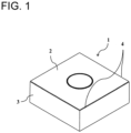
- the coated tool of the present disclosure includes a main surface in a substantially rectangular plate-like shape.
- the main surface is not limited to this shape.
- a coated tool 1 includes a first surface 2 (hereinafter described as a main surface 2) and a second surface 3 and includes a cutting edge 4 on at least a part of a portion where the first surface 2 and the second surface 3 intersect.
- the first surface 2 is a surface called a rake surface
- the second surface 3 is a surface called a flank surface.
- the cutting edge 4 is provided on at least a part of a portion where the rake surface 2 and the flank surface 3 intersect.
- the coated tool 1 includes a base member 5 and a coating layer 7 located on a surface of the base member 5.
- a material constituting the base member 5 of the coated tool 1 may be a hard alloy, a ceramic or a metal.
- the hard alloy may be a cemented carbide including tungsten carbide (WC) and an iron-group metal such as cobalt (Co) or nickel (Ni).
- Another hard alloy may be a Ti-based cermet including titanium carbonitride (TiCN) and iron-group metals such as cobalt (Co) or nickel (Ni).
- the ceramic may be Si 3 N 4 , Al 2 O 3 , diamond or cubic boron nitride (cBN) .
- the metal may be carbon steel, high-speed steel or alloy steel. If used as the coated tool 1, the base member 5 is favorably made of the cemented carbide or cermet among the materials described above in terms of fracture resistance and wear resistance.
- the coating layer 7 includes a TiCNO layer 9 and an Al 2 O 3 layer 11.
- the Al 2 O 3 layer 11 is in contact with the TiCNO layer 9 at a position of the TiCNO layer 9 far from the base member 5.
- the coated tool 1 of the present disclosure includes a first protrusion 13a projecting toward the Al 2 O 3 layer 11. Further, a second protrusion 13b is provided projecting from the first protrusion 13a in a direction intersecting a direction in which the first protrusion 13a projects.
- a protrusion including both the first protrusion 13a and the second protrusion 13b is referred to as a first composite protrusion 14a.
- the TiCNO layer 9 and the Al 2 O 3 layer 11 are less likely to peel off due to the engagement of the first protrusion 13a and the second protrusion 13b with the Al 2 O 3 layer 11.
- the second protrusion 13b is omitted, otherwise the figure would be complicated.
- Both the first protrusion 13a and the second protrusion 13b in the coated tool 1 of the present disclosure include Ti, C, N and O, and have homogeneous compositions.
- the first protrusion 13a and the second protrusion 13b having the homogeneous compositions, the first protrusion 13a and the second protrusion 13b are less likely to be cracked or broken, and the adhesion between the TiCNO layer 9 and the Al 2 O 3 layer 11 is improved as compared with a case where the first protrusion 13a and the second protrusion 13b have different compositions.
- That the first protrusion 13a and the second protrusion 13b have the homogeneous compositions means that the difference between the respective constituents is 5 % or less.
- composition deviation between the respective compositions of the first protrusion 13a and the second protrusion 13b may be 3 % or less.
- the deviation may be 1 % or less.
- the first protrusion 13a and the second protrusion 13b can be obtained by using the same gas when the first protrusion 13a and the second protrusion 13b are formed.
- the TiCNO layer 9 may include a plurality of second protrusions 13b on the first protrusion 13a.
- the first composite protrusion 14a may include a plurality of second protrusions 13b. This makes the TiCNO layer 9 and the Al 2 O 3 layer 11 even less likely to peel off. That the first protrusion 13a includes a plurality of second protrusions 13b means that one first protrusion 13a includes a plurality of second protrusions 13b.
- the second protrusion 13b may project in a direction toward the base member 5. That the second protrusion 13b projects in the direction toward the base member 5 means a state where an axis of the second protrusion 13b intersects the base member 5 when being extended, the axis connecting the apex of the second protrusion 13b and the midpoint of the width of a portion that is the origin of the projection of the second protrusion 13b in the cross-section as illustrated in Fig. 3 .
- the width of a portion of the first protrusion 13a may be larger than the width of the portion of the second protrusion 13b projecting from the first protrusion 13a, the portion being the origin of the projection from the first protrusion 13a.
- the length of the first protrusion 13a may be larger than the length of the second protrusion 13b projecting from the first protrusion 13a.
- the length of the first protrusion 13a means a distance between the apex of the first protrusion 13a and the midpoint of the width of the portion that is the origin of the projection of the first protrusion 13a.
- the length of the second protrusion 13b means a distance between the apex of the second protrusion 13b and the midpoint of the width of the portion that is the origin of the projection of the second protrusion 13b.
- the length of the second protrusion 13b may be 10 to 150 nm.
- the maximum width of the second protrusion 13b may be 50 nm or less.
- the TiCNO layer 9 may include a third protrusion 13c projecting from the second protrusion 13b in the direction intersecting a direction in which the second protrusion 13b projects.
- a protrusion including the first protrusion 13a, the second protrusion 13b, and the third protrusion 13c is referred to as a second composite protrusion 14b.
- the length of the third protrusion 13c may be shorter than the length of the second protrusion 13b. With such a structure, the first protrusion 13a and the second protrusion 13b are less likely to be broken, and the TiCNO layer 9 and the Al 2 O 3 layer 11 are less likely to peel off. As a result, the fracture resistance of the coated tool 1 is improved.
- the length of the third protrusion 13c may be 10 to 70 nm.
- the maximum width of the third protrusion 13c may be 20 nm or less.
- the length of the third protrusion 13c may be larger than the length of the second protrusion 13b.
- the first protrusion 13a may not be formed perpendicularly to the first surface 2 of the base member 5 but may be inclined relative to the first surface 2 of the base member 5.
- composition of the third protrusion 13c may be homogeneous to that of the second protrusion 13b.
- the composition deviation between the third protrusion 13c and the second protrusion 13b may be 5 % or less.
- the deviation may be 3 % or less.
- the deviation may be 1 % or less.
- the average width of the bases of the first protrusions 13a may be 40 to 200 nm.
- the average length of the first protrusions 13a may be 10 to 500 nm. Further, the average length of the first protrusions 13a may be 50 to 300 nm.
- the width of the base of the first protrusion 13a is the width of the portion that is the origin of the projection of the first protrusion 13a.
- the average value of the widths of the bases of the first protrusions 13a is the average value of widths of bases of 20 or more first protrusions 13a.
- the length of the first protrusion 13a means the distance between the apex of the first protrusion 13a and the midpoint of the width of the portion that is the origin of the projection of the first protrusion 13a.
- the average length of the first protrusions 13a is the average value of lengths of 20 or more first protrusions 13a.
- the length of the second protrusion 13b means a distance between the apex of the second protrusion 13b and the midpoint of the width of the portion that is the origin of the projection of the second protrusion 13b.
- the average width of the bases of the first protrusions 13a may be 60 to 120 nm.
- the average length of the first protrusions 13a may be 150 to 230 nm. If the first protrusion 13a has such a shape, the difference between the longest first protrusion 13a and the shortest first protrusion 13a becomes small. If the first protrusion parts 13a are relatively uniform as described above, the TiCNO layer 9 and the Al 2 O 3 layer 11 are even less likely to peel off.
- the average length of the first protrusions 13a may be four times or less the average width of the bases of the first protrusions 13a. With such a structure, the first protrusion 13a is less likely to be broken, so that the TiCNO layer 9 and the Al 2 O 3 layer 11 are even less likely to peel off.
- the average length of the first protrusions 13a may be three times or less the average width of the bases of the first protrusions 13a. As the ratio becomes smaller, the first protrusion 13a is less likely to be broken, so that the TiCNO layer 9 and the Al 2 O 3 layer 11 are even less likely to peel off.
- the average length of the first protrusions 13a may be 2.5 times or less the average width of the bases of the first protrusions 13a.
- the thickness of the TiCNO layer 9 is in the range of 10 nm to 35 nm, the hardness of the TiCNO layer 9 does not decrease, and the Al 2 O 3 layer 11 has an ⁇ -crystal structure.
- the thickness of the TiCNO layer 9 excludes the first protrusion 13a, the second protrusions 13b, and the third protrusions 13c.
- the TiCNO layer 9 may include, for example, 30 to 70 % by atom of titanium, 1 to 70 % by atom of carbon, 1 to 35 % by atom of nitrogen, and 3 to 20 % by atom of oxygen. Further, the TiCNO layer 9 may include 10 % by atom or less of aluminum. The TiCNO layer 9 may include 1 to 10 % by atom of a component such as chlorine or chromium. The TiCNO layer 9 may include other minor components.
- the TiCNO layer 9 and the first protrusion 13a, the second protrusion 13b, and the third protrusion 13c may all have the same composition and may be within the composition range described above.
- the ratio of the number of second composite protrusions 14b to the sum of the number of first composite protrusions 14a and the number of second composite protrusions 14b is 20 % or more in the cross-section orthogonal to the surface of the base member 5. With such a configuration, the coated tool 1 is excellent in impact resistance.
- the TiCNO layer 9 including the first protrusions 13a can be formed on the surface of the base member 5 by chemical vapor deposition (CVD) method under the following conditions.
- the base member 5 may be placed in a chamber of a film formation apparatus, and the TiCNO layer 9 may be formed by, for example, making the following settings: a film formation temperature is 900°C to 990°C, gas pressure is 5 kPa to 40 kPa, and a reactive gas composition is 3 % by volume to 15 % by volume of titanium tetrachloride (TiCl 4 ) gas, 3 % by volume to 10 % by volume of methane (CH 4 ) gas, 3 % by volume to 50 % by volume of nitrogen (N 2 ) gas, 0.5 % by volume to 2.0 % by volume of carbon monoxide (CO) gas, and the rest being hydrogen (H 2 ) gas.
- a film formation temperature is 900°C to 990°C
- gas pressure is 5 kPa to 40 kPa
- a reactive gas composition is 3 % by volume to 15 % by volume of titanium tetrachloride (TiCl 4 ) gas, 3
- the nitrogen (N 2 ) gas in the reactive gas composition is set to 30 % by volume to 50 % by volume, the average width of the bases of the first protrusions 13a tends to be wide and the average length of the first protrusions 13a tends to be short. In other words, under such a condition, it is easy to obtain the first protrusion 13a that is thick, short, and less likely to be broken.
- the film formation temperature is set to the range of 900 to 940°C by lowering the film formation temperature without changing the composition of the source gas, the second protrusion 13b is formed.
- the film formation time may be 30 to 90 minutes in total.
- the second protrusion 13b In the later stage of the formation of the TiCNO layer 9, that is, in the step of forming the second protrusions 13b, if the film formation time is extended, the number of second protrusions 13b increases, and the widths and lengths thereof tend to increase.
- the second protrusion 13b With its projecting direction extending toward the base member 5, is easily formed. In other words, the first composite protrusion 14a is easily formed. If the film formation time is further extended, the third protrusion 13c projecting from the second protrusion 13b is easily formed. In other words, the second composite protrusion 14b is easily formed.
- the Al 2 O 3 layer 11 can be formed by making the following settings: the film formation temperature is 900°C to 990°C, the gas pressure is 5 kPa to 20 kPa, and the composition of the reactive gas is 5 % by volume to 15 % by volume of aluminum trichloride (AlCl 3 ) gas, 0.5 % by volume to 2.5 % by volume of hydrogen chloride (HCl) gas, 0.5 % by volume to 5.0 % by volume of carbon dioxide (CO 2 ) gas, 0 % by volume to 1.0 % by volume of hydrogen sulfide (H 2 S) gas, and the rest being a hydrogen (H 2 ) gas.
- the Al 2 O 3 layer 11 may be made of ⁇ -alumina.
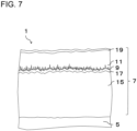
- the coating layer 7 may include a first TiCN layer 15 and a second TiCN layer 17 sequentially from the base member 5.
- the TiCNO layer 9 and the Al 2 O 3 layer 11 may be sequentially provided on the second TiCN layer 17.
- a surface layer 19 including Ti and N may further be provided on the Al 2 O 3 layer 11.
- the second protrusion 13b is omitted.
- the surface layer 19 may be made of other materials except for titanium nitride, such as titanium carbonitride, titanium oxycarbonitride, or chromium nitride.
- the surface layer 19 may be made of a colored material and have a function of easily discriminating whether or not the cutting edge 4 has been used.
- the surface layer 19 may be provided with a thickness of 0.1 um to 3.0 um.
- a base layer (not illustrated) made of TiN may further be provided between the base member 5 and the first TiCN layer 15.
- the base layer has a function of preventing the diffusion of these components into the layer present on the base layer.
- the base layer has a function of preventing the diffusion of these components into the layer present on the base layer.
- the first TiCN layer 15 is present on the base layer, the diffusion of the above components into the first TiCN layer 15 is prevented, and the lowering of the hardness of the first TiCN layer 15 is prevented.
- the carbon component in the base member 5 may be diffused into TiN of the base layer to form TiCN.
- the thickness of the base layer may be set to 0.1 um to 1.0 ⁇ m.
- the thickness of the first TiCN layer 15 may be set to 2 um to 15 um.
- the thickness of the second TiCN layer 17 may be set to 10 nm to 900 nm.
- the first TiCN layer 15 is made of a so-called moderate temperature (MT)-TiCN layer. If the thickness of the first TiCN layer 15 is 2 um to 15 um, which is formed by forming the MT-TiCN layer using a raw material that includes titanium tetrachloride (TiCl 4 ) gas, nitrogen (N 2 ) gas, acetonitrile (CH 3 CN) gas, or the like at a relatively low film formation temperature of 780°C to 880°C, the first TiCN layer 15 has high wear resistance and fracture resistance.
- MT moderate temperature
- the first titanium carbonitride crystal included in the first TiCN layer 15 may be a columnar crystal elongated in the thickness direction of the coating layer 7.
- the second TiCN layer 17 is made of a so-called high temperature (HT)-TiCN layer.
- the HT-TiCN layer may be formed using titanium tetrachloride (TiCl 4 ) gas, nitrogen (N 2 ) gas, methane (CH 4 ) gas, or the like as a source gas and not including acetonitrile (CH 3 CN) gas at a film formation temperature in the range of 900°C to 1050°C.
- the film may be formed at a higher temperature than the first TiCN layer 15.
- the thickness of the second TiCN layer 17 may be from 10 nm to 900 nm.
- an interface layer (not illustrated) may be disposed between the first TiCN layer 15 and the second TiCN layer 17, the interface layer including 30 to 70 % by atom of titanium, 15 to 35 % by atom of carbon, 15 to 35 % by atom of nitrogen, and 2 to 10 % by atom of oxygen.
- the thickness of the interface layer may be from 5 nm to 50 nm.
- a method may be used in which after the formation of the first TiCN layer 15, the film formation chamber is temporarily cooled, a sample is removed into the atmosphere, and then the sample is placed again in the film formation chamber to heat the film formation chamber, thereby forming the second TiCN layer 17.
- the carbon content ratio to the total content of carbon and nitrogen included in the second TiCN layer 17 may be smaller than the carbon content ratio of the first TiCN layer 15. This leads to improvement in the hardness of the first TiCN layer 15. As a result, the wear resistance and the fracture resistance of the coating layer 7 are improved.
- the carbon content ratio is the ratio (C/(C + N)) of the content of carbon to the total content of carbon (C) and nitrogen (N) included.
- the wear resistance and the fracture resistance of the coating layer 7 are further improved. If the carbon content in the first TiCN layer 15 is set to 15 to 29 % by atom and the nitrogen content is set to 22 to 35 % by atom, the wear resistance and the fracture resistance of the coating layer 7 are further enhanced. If the carbon content of the second TiCN layer 17 is set to 13 to 24 % by atom and the nitrogen content is set to 23 to 35 % by atom, the adhesion between the second TiCN layer 17 and the Al 2 O 3 layer 11 is enhanced.
- the first TiCN layer 15 includes 45 to 60 % by atom of titanium, 15 to 29 % by atom of carbon, and 22 to 35 % by atom of nitrogen, the wear resistance and the fracture resistance of the coating layer 7 are higher.
- the first TiCN layer 15 may include 0.5 % or less by atom of oxygen.
- the second TiCN layer 17 includes 48 to 60 % by atom of titanium, 10 to 20 % by atom of carbon, and 15 to 25 % by atom of nitrogen, the second TiCN layer 17 is not broken, and the adhesion between the second TiCN layer 17 and the Al 2 O 3 layer 11 is high.
- the second TiCN layer 17 may include 1 to 10 % by atom of oxygen.
- oxygen may be present in the first TiCN layer 15 and the second TiCN layer 17, and the oxygen present in the second TiCN layer 17 may be more than the oxygen present in the first TiCN layer 15.
- the carbon content and the nitrogen content in each of the first TiCN layer 15 and the second TiCN layer 17 are measured using an energy dispersive X-ray spectrometer (EDS) accompanying a transmission electron microscope (TEM).
- EDS energy dispersive X-ray spectrometer
- TEM transmission electron microscope
- each layer and the shape of a crystal constituting each layer are measurable by observing an electron microscope photograph (scanning electron microscope (SEM) photograph or transmission electron microscope (TEM) photograph) in a cross-section of the tool 1.
- SEM scanning electron microscope
- TEM transmission electron microscope
- the coated tool 1 is designed to perform a cutting process by bringing the cutting edge, formed at an intersection between the rake surface and the flank surface, into contact with a workpiece and can produce the excellent effects described above.
- the coated tool 1 of the present disclosure can be applied to various uses such as wear-resistant parts like sliding parts and molds, excavation tools, tools like edge tools, and impact-resistant parts, and in these cases as well, the coated tool 1 has excellent mechanical reliability.
- metal powder, carbon powder, or the like is suitably added to inorganic powder of carbide, nitride, carbonitride, oxide or the like, which can form a hard alloy constituting the base member by sintering, and these are mixed together, to prepare a mixed powder.
- the mixed powder is used to be molded into a predetermined tool shape by a known molding method such as press-molding, casting molding, extrusion molding and cold isostatic pressing.
- the molded body is sintered in a vacuum or a non-oxidizing atmosphere to produce the base member described above.
- the surface of the base member is then subjected to a polishing process, and a cutting part is subjected to a honing process if desired.
- a coating layer is deposited on the surface by chemical vapor deposition (CVD) method.
- a base member is placed in the chamber, and a TiN layer as a base layer is formed.
- the layer is formed by making the following settings: the film formation temperature is 800°C to 940°C, the gas pressure is 8 kPa to 50 kPa, and the composition of the reactive gas is 0.5 % by volume to 10 % by volume of titanium tetrachloride (TiCl 4 ) gas, 10 % by volume to 60 % by volume of nitrogen (N 2 ) gas, and the rest being hydrogen (H 2 ) gas.
- TiCl 4 titanium tetrachloride
- a first TiCN layer is formed.
- the layer is formed by making the following settings: the film formation temperature is 780°C to 880°C, the gas pressure is 5 kPa to 25 kPa, and the composition of the reactive gas is 0.5 % by volume to 10 % by volume of titanium tetrachloride (TiCl 4 ) gas, 5 % by volume to 60 % by volume of nitrogen (N 2 ) gas, 0.1 % by volume to 3.0 % by volume of acetonitrile (CH 3 CN) gas, and the rest being hydrogen (H 2 ) gas.
- TiCl 4 titanium tetrachloride
- N 2 nitrogen
- CH 3 CN acetonitrile
- a mean crystal width of columnar crystals of titanium carbonitride constituting the first TiCN layer can be made larger on the side of the surface than on the side of the base member by increasing the content ratio of the acetonitrile (CH 3 CN) gas in a later stage of the film formation than in an initial stage of the film formation.
- CH 3 CN acetonitrile
- an interface layer is formed on the first TiCN layer.
- the layer is formed by making the following settings: the film formation temperature is 900°C to 1050°C, the gas pressure is 5 kPa to 40 kPa, and the composition of the reactive gas is 3 % by volume to 30 % by volume of titanium tetrachloride (TiCl 4 ) gas, 3 % by volume to 15 % by volume of methane (CH 4 ) gas, 5 % by volume to 10 % by volume of nitrogen (N 2 ) gas, 0.5 % by volume to 10 % by volume of carbon dioxide (CO 2 ) gas, and the rest being hydrogen (H 2 ) gas.
- TiCl 4 titanium tetrachloride
- a second TiCN layer is formed.
- the layer is formed by making the following settings: the film formation temperature is 900°C to 990°C, the gas pressure is 5 kPa to 40 kPa, and the composition of the reactive gas is 1 % by volume to 4 % by volume of titanium tetrachloride (TiCl 4 ) gas, 5 % by volume to 20 % by volume of nitrogen (N 2 ) gas, 0.1 % by volume to 10 % by volume of methane (CH 4 ) gas, and the rest being hydrogen (H 2 ) gas.
- TiCl 4 titanium tetrachloride
- a TiCNO layer 9 is formed.
- the layer is formed by making the following settings: the film formation temperature is 940°C to 990°C, the gas pressure is 5 kPa to 40 kPa, and the composition of the reactive gas is 3 % by volume to 15 % by volume of titanium tetrachloride (TiCl 4 ) gas, 3 % by volume to 10 % by volume of methane (CH 4 ) gas, 3 % by volume to 50 % by volume of nitrogen (N 2 ) gas, 0.5 % by volume to 2.0 % by volume of carbon oxide (CO) gas, and the rest being hydrogen (H 2 ) gas.
- TiCl 4 titanium tetrachloride
- CH 4 methane
- N 2 nitrogen
- CO carbon oxide
- the film formation temperature is lowered to 900 to 940°C, and the layer is formed so that the total time is 30 to 90 minutes.
- an Al 2 O 3 layer is formed.
- the Al 2 O 3 layer is formed by making the following settings: the film formation temperature is 950°C to 1100°C, the gas pressure is 5 kPa to 20 kPa, and the composition of the reactive gas is 5 % by volume to 15 % by volume of aluminum trichloride (AlCl 3 ) gas, 0.5 % by volume to 2.5 % by volume of hydrogen chloride (HCl) gas, 0.5 % by volume to 5.0 % by volume of carbon dioxide (CO 2 ) gas, 0 % by volume to 1.0 % by volume of hydrogen sulfide (H 2 S) gas, and the rest being hydrogen (H 2 ) gas.
- AlCl 3 aluminum trichloride
- HCl hydrogen chloride
- CO 2 carbon dioxide
- H 2 S hydrogen sulfide
- a TiN layer which is a surface layer is formed.
- the layer is formed by making the following settings: the film formation temperature is 960°C to 1100°C, the gas pressure is 10 kPa to 85 kPa, and the reactive gas composition is 0.1 % by volume to 10 % by volume of titanium tetrachloride (TiCl 4 ) gas, 10 % by volume to 60 % by volume of nitrogen (N 2 ) gas, and the rest being hydrogen (H 2 ) gas.
- TiCl 4 titanium tetrachloride
- the polishing process is performed on at least a cutting part of the surface of the formed coating layer if desired.
- the cutting part is smoothly processed to prevent the welding of the workpiece, and a tool with more excellent fracture resistance is obtained.
- the example has been shown where the first TiCN layer, the second TiCN layer, and the surface layer are provided, but the TiCNO layer and the Al 2 O 3 layer may be directly laminated on the surface of the base member.
- the coated tool 1 of the present disclosure has been described above, the present disclosure is not limited to the embodiment described above, and various improvements and modifications may be made within a range not departing from the gist of the present disclosure.
- a cutting tool 101 of the present disclosure is, for example, a rod-shaped body extending from a first end (the upper end in Fig. 8 ) toward a second end (the lower end in Fig. 8 ).
- the cutting tool 101 includes a holder 105 including a pocket 103 on a first end side (tip side), and the coated tool 1 located in the pocket 103. Because including the coated tool 1, the cutting tool 101 can perform a stable cutting process over a long period of time.
- the pocket 103 is a part that permits attachment of the coated tool 1.
- the pocket 103 includes a seating surface parallel to a lower surface of the holder 105, and a constraining side surface inclined relative to the seating surface.
- the pocket 103 opens into a side of the first end of the holder 105.
- the coated tool 1 is located in the pocket 103. At this time, the lower surface of the coated tool 1 may be in direct contact with the pocket 103, or a sheet (not illustrated) may be disposed between the coated tool 1 and the pocket 103.
- the coated tool 1 is mounted on the holder 105 such that at least a part of a portion used as a cutting edge 4 at a ridge line where the first surface 3 and the second surface 5 intersect projects outward from the holder 105.
- the coated tool 1 is attached to the holder 105 with a fixing screw 107. That is, the coated tool 1 is attached to the holder 105 by inserting the fixing screw 107 into a through hole 17 of the coated tool 1, inserting the tip of the fixing screw 107 into a screw hole (not illustrated) formed in the pocket 103, and screwing the screw parts together.
- steel cast iron or the like
- steel having high toughness may be used.
- a cutting tool 101 used for a so-called turning process is exemplified.
- the turning process include an inner-diameter process, an outer-diameter process, and grooving process.
- the cutting tool 101 is not limited to a tool used for the turning process.
- the coated tools 1 of the above embodiment are applicable to the cutting tools for use in the milling process.
- an amount of 6 % by mass of metal cobalt powder having a mean particle diameter of 1.2 um, an amount of 0.5 % by mass of titanium carbide powder having a mean particle diameter of 2.0 um, an amount of 5 % by mass of niobium carbide powder having a mean particle diameter of 2.0 ⁇ m, and the rest, namely, tungsten carbide powder having a mean particle diameter of 1.5 um were added and mixed together.
- the manufactured base member was then subjected to a brushing process, and a part of the base member which served as a cutting edge was subjected to round honing.
- the coating layer was formed on the above base member of cemented carbide by combining individual film formation conditions shown in Table 1 by chemical vapor deposition (CVD) method as described in Tables 2 and 3, thereby manufacturing a coated tool.
- CVD chemical vapor deposition
- the cross-section including the coating layer of the sample was subjected to SEM observation to observe the presence or absence of the first protrusion, the second protrusion, and the third protrusion and the forms of the first protrusion, the second protrusion and the third protrusion.
- Tables 2 and 3 show the ratio of the number of first composite protrusions to the sum of the number of first composite protrusions and the number of second composite protrusions and the ratio of the number of second composite protrusions. Then, an intermittent cutting test was conducted using the obtained coated tool under the following conditions to evaluate the fracture resistance. Tables 2 and 3 show the test results.
- Table 2 describes how many times the number of impact times of Sample No. 1 each sample withstood, based on the number of impact times of Sample No. 1.
- Table 3 describes how many times the number of impact times of Sample No. 8 each sample withstood, based on the number of impact times of Sample No. 8.
- Samples No. 9 to 14 including the first composite protrusion that includes the second protrusion the cutting performance is more excellent than in Sample No. 8.
- Samples No. 11 and (inventive) No. 14 including the second composite protrusion that includes the third protrusion more excellent cutting performance was obtained.
- the coated tool of the present disclosure has cutting performance superior to that of the sample without the second protrusion, that is, the first composite protrusion.
Description
- The present disclosure relates to a coated tool including a coating layer on a surface of a base member and a cutting tool including the coated tool.
- A coated tool such as a cutting tool has been known in which a coating layer formed by laminating an Al2O3 layer is formed on a surface of a base member such as a cemented carbide, a cermet or a ceramic through a bonding film.
- With the recent increase in the efficiency of a cutting process, cutting tools are increasingly used in heavy intermittent cutting where large impacts are applied to the cutting edge. Under such severe cutting conditions, a large impact is applied to the coating layer, and chipping or peeling of the coating layer tends to occur. Therefore, improvement of fracture resistance is required for the coating layer in addition to wear resistance.
- As a technique for improving the fracture resistance in the cutting tool,
Patent Document 1 discloses a technique in which a bonding film and an Al2O3 layer are formed sequentially, and a dendrite extending toward the Al2O3 layer side and a branched protrusion extending from the dendrite are provided on the bonding film, thereby enhancing the adhesion between the bonding film and the Al2O3 layer and preventing the peeling of the coating layer.Patent Document 1 discloses that the dendrite is Ti (CO) or Ti (CNO) and that the branched protrusion is (TiAl)(CNO).Patent Document 1 describes that after the formation of the dendrite, the flow of a source gas is stopped once, and while the temperature is maintained, the pressure and the type of the source gas are changed to form the dendrite having a composition different from that of the dendrite. - Patent Document 1:
Japanese Patent No. 5303732 - From
JP 2004 074324 A US 2013/149527 A1 andKR 2010 0135641 A - The present invention provides a coated tool with the features according to
claim 1 and a cutting tool with the features according toclaim 7. Further embodiments of the coated tool are described in the dependent claims. -
-
Fig. 1 is a schematic perspective view illustrating an example of a coated tool of the present disclosure. -
Fig. 2 is a schematic view for explaining a configuration of a cross-section of a coating layer in the coated tool ofFig. 1 . -
Fig. 3 is an enlarged view of a main part of the coated tool of the present disclosure for explaining a configuration in the vicinity of the TiCNO layer and the Al2O3 layer. -
Fig. 4 is an enlarged view of the main part of the coated tool of the present disclosure for explaining the configuration in the vicinity of the TiCNO layer and the Al2O3 layer. -
Fig. 5 is an enlarged view of the main part of the coated tool of the present disclosure for explaining the configuration in the vicinity of the TiCNO layer and the Al2O3 layer. -
Fig. 6 is an enlarged view of the main part of the coated tool of the present disclosure for explaining a configuration in the vicinity of the TiCNO layer and the Al2O3 layer. -
Fig. 7 is a schematic view for explaining a configuration of a cross-section of another form of the coating layer in the coated tool of the present disclosure. -
Fig. 8 is a plan view illustrating an example of a cutting tool of the present disclosure. - In the example illustrated in
Fig. 1 , the coated tool of the present disclosure includes a main surface in a substantially rectangular plate-like shape. However, the main surface is not limited to this shape. A coatedtool 1 includes a first surface 2 (hereinafter described as a main surface 2) and asecond surface 3 and includes acutting edge 4 on at least a part of a portion where thefirst surface 2 and thesecond surface 3 intersect. Thefirst surface 2 is a surface called a rake surface, and thesecond surface 3 is a surface called a flank surface. Hence it can also be said that thecutting edge 4 is provided on at least a part of a portion where therake surface 2 and theflank surface 3 intersect. - As illustrated in a schematic view for explaining a configuration of a cross-section of a
coating layer 7 in the coatedtool 1 illustrated inFig. 2 , the coatedtool 1 includes abase member 5 and acoating layer 7 located on a surface of thebase member 5. - A material constituting the
base member 5 of the coatedtool 1 may be a hard alloy, a ceramic or a metal. The hard alloy may be a cemented carbide including tungsten carbide (WC) and an iron-group metal such as cobalt (Co) or nickel (Ni). Another hard alloy may be a Ti-based cermet including titanium carbonitride (TiCN) and iron-group metals such as cobalt (Co) or nickel (Ni). The ceramic may be Si3N4, Al2O3, diamond or cubic boron nitride (cBN) . The metal may be carbon steel, high-speed steel or alloy steel. If used as the coatedtool 1, thebase member 5 is favorably made of the cemented carbide or cermet among the materials described above in terms of fracture resistance and wear resistance. - The
coating layer 7 includes aTiCNO layer 9 and an Al2O3 layer 11. The Al2O3 layer 11 is in contact with theTiCNO layer 9 at a position of theTiCNO layer 9 far from thebase member 5. - As illustrated in
Fig. 3 to 6 , the coatedtool 1 of the present disclosure includes afirst protrusion 13a projecting toward the Al2O3 layer 11. Further, asecond protrusion 13b is provided projecting from thefirst protrusion 13a in a direction intersecting a direction in which thefirst protrusion 13a projects. Hereinafter, a protrusion including both thefirst protrusion 13a and thesecond protrusion 13b is referred to as afirst composite protrusion 14a. - In the coated
tool 1 of the present disclosure, since thefirst protrusion 13a projects toward the Al2O3 layer 11 and thesecond protrusion 13b projects from thefirst protrusion 13a in the direction intersecting the direction in which thefirst protrusion 13a projects, theTiCNO layer 9 and the Al2O3 layer 11 are less likely to peel off due to the engagement of thefirst protrusion 13a and thesecond protrusion 13b with the Al2O3 layer 11. InFig. 2 , thesecond protrusion 13b is omitted, otherwise the figure would be complicated. - Both the
first protrusion 13a and thesecond protrusion 13b in the coatedtool 1 of the present disclosure include Ti, C, N and O, and have homogeneous compositions. With thefirst protrusion 13a and thesecond protrusion 13b having the homogeneous compositions, thefirst protrusion 13a and thesecond protrusion 13b are less likely to be cracked or broken, and the adhesion between theTiCNO layer 9 and the Al2O3 layer 11 is improved as compared with a case where thefirst protrusion 13a and thesecond protrusion 13b have different compositions. - That the
first protrusion 13a and thesecond protrusion 13b have the homogeneous compositions means that the difference between the respective constituents is 5 % or less. - In addition, the composition deviation between the respective compositions of the
first protrusion 13a and thesecond protrusion 13b may be 3 % or less. The deviation may be 1 % or less. - The
first protrusion 13a and thesecond protrusion 13b can be obtained by using the same gas when thefirst protrusion 13a and thesecond protrusion 13b are formed. - The TiCNO
layer 9 may include a plurality ofsecond protrusions 13b on thefirst protrusion 13a. In other words, the firstcomposite protrusion 14a may include a plurality ofsecond protrusions 13b. This makes the TiCNOlayer 9 and the Al2O3 layer 11 even less likely to peel off. That thefirst protrusion 13a includes a plurality ofsecond protrusions 13b means that onefirst protrusion 13a includes a plurality ofsecond protrusions 13b. - As illustrated in
Fig. 3 , thesecond protrusion 13b may project in a direction toward thebase member 5. That thesecond protrusion 13b projects in the direction toward thebase member 5 means a state where an axis of thesecond protrusion 13b intersects thebase member 5 when being extended, the axis connecting the apex of thesecond protrusion 13b and the midpoint of the width of a portion that is the origin of the projection of thesecond protrusion 13b in the cross-section as illustrated inFig. 3 . - In the cross-section as illustrated in
Fig. 3 , the width of a portion of thefirst protrusion 13a, the portion being the origin of the projection from theTiCNO layer 9, may be larger than the width of the portion of thesecond protrusion 13b projecting from thefirst protrusion 13a, the portion being the origin of the projection from thefirst protrusion 13a. The length of thefirst protrusion 13a may be larger than the length of thesecond protrusion 13b projecting from thefirst protrusion 13a. Note that the length of thefirst protrusion 13a means a distance between the apex of thefirst protrusion 13a and the midpoint of the width of the portion that is the origin of the projection of thefirst protrusion 13a. Similarly, the length of thesecond protrusion 13b means a distance between the apex of thesecond protrusion 13b and the midpoint of the width of the portion that is the origin of the projection of thesecond protrusion 13b. - The length of the
second protrusion 13b may be 10 to 150 nm. The maximum width of thesecond protrusion 13b may be 50 nm or less. - Further, as illustrated in
Fig. 6 , theTiCNO layer 9 may include athird protrusion 13c projecting from thesecond protrusion 13b in the direction intersecting a direction in which thesecond protrusion 13b projects. A protrusion including thefirst protrusion 13a, thesecond protrusion 13b, and thethird protrusion 13c is referred to as a second composite protrusion 14b. - The length of the
third protrusion 13c may be shorter than the length of thesecond protrusion 13b. With such a structure, thefirst protrusion 13a and thesecond protrusion 13b are less likely to be broken, and theTiCNO layer 9 and the Al2O3 layer 11 are less likely to peel off. As a result, the fracture resistance of thecoated tool 1 is improved. The length of thethird protrusion 13c may be 10 to 70 nm. The maximum width of thethird protrusion 13c may be 20 nm or less. - The length of the
third protrusion 13c may be larger than the length of thesecond protrusion 13b. With such a structure, even if the number of second composite protrusions 14b is small, theTiCNO layer 9 and the Al2O3 layer 11 are less likely to peel off. - The
first protrusion 13a may not be formed perpendicularly to thefirst surface 2 of thebase member 5 but may be inclined relative to thefirst surface 2 of thebase member 5. - Note that the composition of the
third protrusion 13c may be homogeneous to that of thesecond protrusion 13b. The composition deviation between thethird protrusion 13c and thesecond protrusion 13b may be 5 % or less. The deviation may be 3 % or less. The deviation may be 1 % or less. - In the cross-section orthogonal to the surface of the
base member 5, the average width of the bases of thefirst protrusions 13a may be 40 to 200 nm. The average length of thefirst protrusions 13a may be 10 to 500 nm. Further, the average length of thefirst protrusions 13a may be 50 to 300 nm. - The width of the base of the
first protrusion 13a is the width of the portion that is the origin of the projection of thefirst protrusion 13a. The average value of the widths of the bases of thefirst protrusions 13a is the average value of widths of bases of 20 or morefirst protrusions 13a. The length of thefirst protrusion 13a means the distance between the apex of thefirst protrusion 13a and the midpoint of the width of the portion that is the origin of the projection of thefirst protrusion 13a. The average length of thefirst protrusions 13a is the average value of lengths of 20 or morefirst protrusions 13a. Similarly, the length of thesecond protrusion 13b means a distance between the apex of thesecond protrusion 13b and the midpoint of the width of the portion that is the origin of the projection of thesecond protrusion 13b. - The average width of the bases of the
first protrusions 13a may be 60 to 120 nm. The average length of thefirst protrusions 13a may be 150 to 230 nm. If thefirst protrusion 13a has such a shape, the difference between the longestfirst protrusion 13a and the shortestfirst protrusion 13a becomes small. If thefirst protrusion parts 13a are relatively uniform as described above, theTiCNO layer 9 and the Al2O3 layer 11 are even less likely to peel off. - The average length of the
first protrusions 13a may be four times or less the average width of the bases of thefirst protrusions 13a. With such a structure, thefirst protrusion 13a is less likely to be broken, so that theTiCNO layer 9 and the Al2O3 layer 11 are even less likely to peel off. The average length of thefirst protrusions 13a may be three times or less the average width of the bases of thefirst protrusions 13a. As the ratio becomes smaller, thefirst protrusion 13a is less likely to be broken, so that theTiCNO layer 9 and the Al2O3 layer 11 are even less likely to peel off. In particular, the average length of thefirst protrusions 13a may be 2.5 times or less the average width of the bases of thefirst protrusions 13a. - If the thickness of the
TiCNO layer 9 is in the range of 10 nm to 35 nm, the hardness of theTiCNO layer 9 does not decrease, and the Al2O3 layer 11 has an α-crystal structure. Here, the thickness of theTiCNO layer 9 excludes thefirst protrusion 13a, thesecond protrusions 13b, and thethird protrusions 13c. - The
TiCNO layer 9 may include, for example, 30 to 70 % by atom of titanium, 1 to 70 % by atom of carbon, 1 to 35 % by atom of nitrogen, and 3 to 20 % by atom of oxygen. Further, theTiCNO layer 9 may include 10 % by atom or less of aluminum. TheTiCNO layer 9 may include 1 to 10 % by atom of a component such as chlorine or chromium. TheTiCNO layer 9 may include other minor components. - In the
coated tool 1 of the present disclosure, theTiCNO layer 9 and thefirst protrusion 13a, thesecond protrusion 13b, and thethird protrusion 13c may all have the same composition and may be within the composition range described above. - Further, in the
coated tool 1 of the present disclosure, the ratio of the number of second composite protrusions 14b to the sum of the number of firstcomposite protrusions 14a and the number of second composite protrusions 14b is 20 % or more in the cross-section orthogonal to the surface of thebase member 5. With such a configuration, thecoated tool 1 is excellent in impact resistance. - The
TiCNO layer 9 including thefirst protrusions 13a can be formed on the surface of thebase member 5 by chemical vapor deposition (CVD) method under the following conditions. - The
base member 5 may be placed in a chamber of a film formation apparatus, and theTiCNO layer 9 may be formed by, for example, making the following settings: a film formation temperature is 900°C to 990°C, gas pressure is 5 kPa to 40 kPa, and a reactive gas composition is 3 % by volume to 15 % by volume of titanium tetrachloride (TiCl4) gas, 3 % by volume to 10 % by volume of methane (CH4) gas, 3 % by volume to 50 % by volume of nitrogen (N2) gas, 0.5 % by volume to 2.0 % by volume of carbon monoxide (CO) gas, and the rest being hydrogen (H2) gas. If the nitrogen (N2) gas in the reactive gas composition is set to 30 % by volume to 50 % by volume, the average width of the bases of thefirst protrusions 13a tends to be wide and the average length of thefirst protrusions 13a tends to be short. In other words, under such a condition, it is easy to obtain thefirst protrusion 13a that is thick, short, and less likely to be broken. - In a later stage of the formation of the
TiCNO layer 9, if the film formation temperature is set to the range of 900 to 940°C by lowering the film formation temperature without changing the composition of the source gas, thesecond protrusion 13b is formed. The film formation time may be 30 to 90 minutes in total. - In the later stage of the formation of the
TiCNO layer 9, that is, in the step of forming thesecond protrusions 13b, if the film formation time is extended, the number ofsecond protrusions 13b increases, and the widths and lengths thereof tend to increase. Thesecond protrusion 13b, with its projecting direction extending toward thebase member 5, is easily formed. In other words, the firstcomposite protrusion 14a is easily formed. If the film formation time is further extended, thethird protrusion 13c projecting from thesecond protrusion 13b is easily formed. In other words, the second composite protrusion 14b is easily formed. - After the formation of the
TiCNO layer 9, the Al2O3 layer 11 can be formed by making the following settings: the film formation temperature is 900°C to 990°C, the gas pressure is 5 kPa to 20 kPa, and the composition of the reactive gas is 5 % by volume to 15 % by volume of aluminum trichloride (AlCl3) gas, 0.5 % by volume to 2.5 % by volume of hydrogen chloride (HCl) gas, 0.5 % by volume to 5.0 % by volume of carbon dioxide (CO2) gas, 0 % by volume to 1.0 % by volume of hydrogen sulfide (H2S) gas, and the rest being a hydrogen (H2) gas. The Al2O3 layer 11 may be made of α-alumina. - An example in which the
TiCNO layer 9 and the Al2O3 layer 11 are sequentially formed on thebase member 5 has been described. As illustrated inFig. 7 , thecoating layer 7 may include afirst TiCN layer 15 and asecond TiCN layer 17 sequentially from thebase member 5. TheTiCNO layer 9 and the Al2O3 layer 11 may be sequentially provided on thesecond TiCN layer 17. In addition, asurface layer 19 including Ti and N may further be provided on the Al2O3 layer 11. InFig. 7 , thesecond protrusion 13b is omitted. - The
surface layer 19 may be made of other materials except for titanium nitride, such as titanium carbonitride, titanium oxycarbonitride, or chromium nitride. Thesurface layer 19 may be made of a colored material and have a function of easily discriminating whether or not thecutting edge 4 has been used. Thesurface layer 19 may be provided with a thickness of 0.1 um to 3.0 um. In addition, a base layer (not illustrated) made of TiN may further be provided between thebase member 5 and thefirst TiCN layer 15. - If the
base member 5 includes components such as Co, carbon (C), or tungsten (W), the base layer has a function of preventing the diffusion of these components into the layer present on the base layer. For example, if thefirst TiCN layer 15 is present on the base layer, the diffusion of the above components into thefirst TiCN layer 15 is prevented, and the lowering of the hardness of thefirst TiCN layer 15 is prevented. Alternatively, the carbon component in thebase member 5 may be diffused into TiN of the base layer to form TiCN. The thickness of the base layer may be set to 0.1 um to 1.0 µm. - If the
coated tool 1 of the present disclosure includes afirst TiCN layer 15, the thickness of thefirst TiCN layer 15 may be set to 2 um to 15 um. The thickness of thesecond TiCN layer 17 may be set to 10 nm to 900 nm. - The
first TiCN layer 15 is made of a so-called moderate temperature (MT)-TiCN layer. If the thickness of thefirst TiCN layer 15 is 2 um to 15 um, which is formed by forming the MT-TiCN layer using a raw material that includes titanium tetrachloride (TiCl4) gas, nitrogen (N2) gas, acetonitrile (CH3CN) gas, or the like at a relatively low film formation temperature of 780°C to 880°C, thefirst TiCN layer 15 has high wear resistance and fracture resistance. - The first titanium carbonitride crystal included in the
first TiCN layer 15 may be a columnar crystal elongated in the thickness direction of thecoating layer 7. - The
second TiCN layer 17 is made of a so-called high temperature (HT)-TiCN layer. The HT-TiCN layer may be formed using titanium tetrachloride (TiCl4) gas, nitrogen (N2) gas, methane (CH4) gas, or the like as a source gas and not including acetonitrile (CH3CN) gas at a film formation temperature in the range of 900°C to 1050°C. The film may be formed at a higher temperature than thefirst TiCN layer 15. The thickness of thesecond TiCN layer 17 may be from 10 nm to 900 nm. - Here, an interface layer (not illustrated) may be disposed between the
first TiCN layer 15 and thesecond TiCN layer 17, the interface layer including 30 to 70 % by atom of titanium, 15 to 35 % by atom of carbon, 15 to 35 % by atom of nitrogen, and 2 to 10 % by atom of oxygen. The thickness of the interface layer may be from 5 nm to 50 nm. - Instead of forming the interface layer, a method may be used in which after the formation of the
first TiCN layer 15, the film formation chamber is temporarily cooled, a sample is removed into the atmosphere, and then the sample is placed again in the film formation chamber to heat the film formation chamber, thereby forming thesecond TiCN layer 17. - The carbon content ratio to the total content of carbon and nitrogen included in the
second TiCN layer 17 may be smaller than the carbon content ratio of thefirst TiCN layer 15. This leads to improvement in the hardness of thefirst TiCN layer 15. As a result, the wear resistance and the fracture resistance of thecoating layer 7 are improved. Here, the carbon content ratio is the ratio (C/(C + N)) of the content of carbon to the total content of carbon (C) and nitrogen (N) included. - If the carbon content ratio of the
first TiCN layer 15 is set to 0.52 to 0.57 and the carbon content ratio of thesecond TiCN layer 17 is set to 0.42 to 0.51, the wear resistance and the fracture resistance of thecoating layer 7 are further improved. If the carbon content in thefirst TiCN layer 15 is set to 15 to 29 % by atom and the nitrogen content is set to 22 to 35 % by atom, the wear resistance and the fracture resistance of thecoating layer 7 are further enhanced. If the carbon content of thesecond TiCN layer 17 is set to 13 to 24 % by atom and the nitrogen content is set to 23 to 35 % by atom, the adhesion between thesecond TiCN layer 17 and the Al2O3 layer 11 is enhanced. - If the
first TiCN layer 15 includes 45 to 60 % by atom of titanium, 15 to 29 % by atom of carbon, and 22 to 35 % by atom of nitrogen, the wear resistance and the fracture resistance of thecoating layer 7 are higher. Thefirst TiCN layer 15 may include 0.5 % or less by atom of oxygen. If thesecond TiCN layer 17 includes 48 to 60 % by atom of titanium, 10 to 20 % by atom of carbon, and 15 to 25 % by atom of nitrogen, thesecond TiCN layer 17 is not broken, and the adhesion between thesecond TiCN layer 17 and the Al2O3 layer 11 is high. Thesecond TiCN layer 17 may include 1 to 10 % by atom of oxygen. - That is, oxygen may be present in the
first TiCN layer 15 and thesecond TiCN layer 17, and the oxygen present in thesecond TiCN layer 17 may be more than the oxygen present in thefirst TiCN layer 15. - Note that the carbon content and the nitrogen content in each of the
first TiCN layer 15 and thesecond TiCN layer 17 are measured using an energy dispersive X-ray spectrometer (EDS) accompanying a transmission electron microscope (TEM). - The structure and thickness of each layer and the shape of a crystal constituting each layer are measurable by observing an electron microscope photograph (scanning electron microscope (SEM) photograph or transmission electron microscope (TEM) photograph) in a cross-section of the
tool 1. - Further, the
coated tool 1 is designed to perform a cutting process by bringing the cutting edge, formed at an intersection between the rake surface and the flank surface, into contact with a workpiece and can produce the excellent effects described above. In addition to the cutting tool of the present disclosure, thecoated tool 1 of the present disclosure can be applied to various uses such as wear-resistant parts like sliding parts and molds, excavation tools, tools like edge tools, and impact-resistant parts, and in these cases as well, thecoated tool 1 has excellent mechanical reliability. - Next, an example of a method for manufacturing the tool of the present disclosure will be described.
- Firstly, metal powder, carbon powder, or the like is suitably added to inorganic powder of carbide, nitride, carbonitride, oxide or the like, which can form a hard alloy constituting the base member by sintering, and these are mixed together, to prepare a mixed powder. Then, the mixed powder is used to be molded into a predetermined tool shape by a known molding method such as press-molding, casting molding, extrusion molding and cold isostatic pressing. The molded body is sintered in a vacuum or a non-oxidizing atmosphere to produce the base member described above. The surface of the base member is then subjected to a polishing process, and a cutting part is subjected to a honing process if desired.
- Subsequently, a coating layer is deposited on the surface by chemical vapor deposition (CVD) method.
- Firstly, a base member is placed in the chamber, and a TiN layer as a base layer is formed. The layer is formed by making the following settings: the film formation temperature is 800°C to 940°C, the gas pressure is 8 kPa to 50 kPa, and the composition of the reactive gas is 0.5 % by volume to 10 % by volume of titanium tetrachloride (TiCl4) gas, 10 % by volume to 60 % by volume of nitrogen (N2) gas, and the rest being hydrogen (H2) gas.
- Next, a first TiCN layer is formed. The layer is formed by making the following settings: the film formation temperature is 780°C to 880°C, the gas pressure is 5 kPa to 25 kPa, and the composition of the reactive gas is 0.5 % by volume to 10 % by volume of titanium tetrachloride (TiCl4) gas, 5 % by volume to 60 % by volume of nitrogen (N2) gas, 0.1 % by volume to 3.0 % by volume of acetonitrile (CH3CN) gas, and the rest being hydrogen (H2) gas. At this time, a mean crystal width of columnar crystals of titanium carbonitride constituting the first TiCN layer can be made larger on the side of the surface than on the side of the base member by increasing the content ratio of the acetonitrile (CH3CN) gas in a later stage of the film formation than in an initial stage of the film formation.
- Then, an interface layer is formed on the first TiCN layer. The layer is formed by making the following settings: the film formation temperature is 900°C to 1050°C, the gas pressure is 5 kPa to 40 kPa, and the composition of the reactive gas is 3 % by volume to 30 % by volume of titanium tetrachloride (TiCl4) gas, 3 % by volume to 15 % by volume of methane (CH4) gas, 5 % by volume to 10 % by volume of nitrogen (N2) gas, 0.5 % by volume to 10 % by volume of carbon dioxide (CO2) gas, and the rest being hydrogen (H2) gas.
- Next, a second TiCN layer is formed. The layer is formed by making the following settings: the film formation temperature is 900°C to 990°C, the gas pressure is 5 kPa to 40 kPa, and the composition of the reactive gas is 1 % by volume to 4 % by volume of titanium tetrachloride (TiCl4) gas, 5 % by volume to 20 % by volume of nitrogen (N2) gas, 0.1 % by volume to 10 % by volume of methane (CH4) gas, and the rest being hydrogen (H2) gas.
- Subsequently, a
TiCNO layer 9 is formed. Firstly, the layer is formed by making the following settings: the film formation temperature is 940°C to 990°C, the gas pressure is 5 kPa to 40 kPa, and the composition of the reactive gas is 3 % by volume to 15 % by volume of titanium tetrachloride (TiCl4) gas, 3 % by volume to 10 % by volume of methane (CH4) gas, 3 % by volume to 50 % by volume of nitrogen (N2) gas, 0.5 % by volume to 2.0 % by volume of carbon oxide (CO) gas, and the rest being hydrogen (H2) gas. Next, the film formation temperature is lowered to 900 to 940°C, and the layer is formed so that the total time is 30 to 90 minutes. Then, an Al2O3 layer is formed. The Al2O3 layer is formed by making the following settings: the film formation temperature is 950°C to 1100°C, the gas pressure is 5 kPa to 20 kPa, and the composition of the reactive gas is 5 % by volume to 15 % by volume of aluminum trichloride (AlCl3) gas, 0.5 % by volume to 2.5 % by volume of hydrogen chloride (HCl) gas, 0.5 % by volume to 5.0 % by volume of carbon dioxide (CO2) gas, 0 % by volume to 1.0 % by volume of hydrogen sulfide (H2S) gas, and the rest being hydrogen (H2) gas. - Then, a TiN layer which is a surface layer is formed. The layer is formed by making the following settings: the film formation temperature is 960°C to 1100°C, the gas pressure is 10 kPa to 85 kPa, and the reactive gas composition is 0.1 % by volume to 10 % by volume of titanium tetrachloride (TiCl4) gas, 10 % by volume to 60 % by volume of nitrogen (N2) gas, and the rest being hydrogen (H2) gas.
- Thereafter, the polishing process is performed on at least a cutting part of the surface of the formed coating layer if desired. By the polishing process, the cutting part is smoothly processed to prevent the welding of the workpiece, and a tool with more excellent fracture resistance is obtained.
- In the above example, the example has been shown where the first TiCN layer, the second TiCN layer, and the surface layer are provided, but the TiCNO layer and the Al2O3 layer may be directly laminated on the surface of the base member.
- Although the
coated tool 1 of the present disclosure has been described above, the present disclosure is not limited to the embodiment described above, and various improvements and modifications may be made within a range not departing from the gist of the present disclosure. - Next, the cutting tool of the present disclosure will be described with reference to the drawings.
- As illustrated in
Fig. 8 , acutting tool 101 of the present disclosure is, for example, a rod-shaped body extending from a first end (the upper end inFig. 8 ) toward a second end (the lower end inFig. 8 ). As illustrated inFig. 8 , thecutting tool 101 includes aholder 105 including apocket 103 on a first end side (tip side), and thecoated tool 1 located in thepocket 103. Because including thecoated tool 1, thecutting tool 101 can perform a stable cutting process over a long period of time. - The
pocket 103 is a part that permits attachment of thecoated tool 1. Thepocket 103 includes a seating surface parallel to a lower surface of theholder 105, and a constraining side surface inclined relative to the seating surface. Thepocket 103 opens into a side of the first end of theholder 105. - The
coated tool 1 is located in thepocket 103. At this time, the lower surface of thecoated tool 1 may be in direct contact with thepocket 103, or a sheet (not illustrated) may be disposed between thecoated tool 1 and thepocket 103. - The
coated tool 1 is mounted on theholder 105 such that at least a part of a portion used as acutting edge 4 at a ridge line where thefirst surface 3 and thesecond surface 5 intersect projects outward from theholder 105. In the present embodiment, thecoated tool 1 is attached to theholder 105 with a fixingscrew 107. That is, thecoated tool 1 is attached to theholder 105 by inserting the fixingscrew 107 into a throughhole 17 of thecoated tool 1, inserting the tip of the fixingscrew 107 into a screw hole (not illustrated) formed in thepocket 103, and screwing the screw parts together. - As the material of the
holder 105, steel, cast iron or the like can be used. Among these members, steel having high toughness may be used. - In the present embodiment, a
cutting tool 101 used for a so-called turning process is exemplified. Examples of the turning process include an inner-diameter process, an outer-diameter process, and grooving process. Note that thecutting tool 101 is not limited to a tool used for the turning process. For example, thecoated tools 1 of the above embodiment are applicable to the cutting tools for use in the milling process. - Firstly, an amount of 6 % by mass of metal cobalt powder having a mean particle diameter of 1.2 um, an amount of 0.5 % by mass of titanium carbide powder having a mean particle diameter of 2.0 um, an amount of 5 % by mass of niobium carbide powder having a mean particle diameter of 2.0 µm, and the rest, namely, tungsten carbide powder having a mean particle diameter of 1.5 um were added and mixed together. This was molded into a tool shape (CNMG120408) by press molding, followed by a debindering process. This was then sintered in vacuum at 1500°C and 0.01 Pa for one hour, thereby manufacturing a base member composed of cemented carbide. The manufactured base member was then subjected to a brushing process, and a part of the base member which served as a cutting edge was subjected to round honing.
- Next, the coating layer was formed on the above base member of cemented carbide by combining individual film formation conditions shown in Table 1 by chemical vapor deposition (CVD) method as described in Tables 2 and 3, thereby manufacturing a coated tool. In Table 1, each compound is represented by a chemical symbol.
- The cross-section including the coating layer of the sample was subjected to SEM observation to observe the presence or absence of the first protrusion, the second protrusion, and the third protrusion and the forms of the first protrusion, the second protrusion and the third protrusion. Tables 2 and 3 show the ratio of the number of first composite protrusions to the sum of the number of first composite protrusions and the number of second composite protrusions and the ratio of the number of second composite protrusions. Then, an intermittent cutting test was conducted using the obtained coated tool under the following conditions to evaluate the fracture resistance. Tables 2 and 3 show the test results.
-
- Workpiece: chromium molybdenum steel with four flutes (SCM440)
- Tool Shape: CNMG120408
- Cutting speed: 300 m/min
- Feed speed: 0.3 mm/rev
- Depth of Cut: 1.5 mm
- Others: Using water-soluble cutting fluid
- Evaluation item: The number of impacts before reaching peeling of Al2O3 layer was measured.
- In all of Samples No. 1 to 7 shown in Table 2, a TiCNO layer was formed directly on the base member, and an Al2O3 layer was formed thereon. In Sample No. 1 where the TiCNO layer was formed at 970°C for 60 minutes, the first protrusion was formed, but the second protrusion and the third protrusion were not formed. That is, Sample No. 1 does not include the first composite protrusion and the second composite protrusion.
- Table 2 describes how many times the number of impact times of Sample No. 1 each sample withstood, based on the number of impact times of Sample No. 1.
- In Samples No. 2 to 7 including the first composite protrusion that includes the second protrusion, the cutting performance is superior to that in Sample No. 1. In Samples No. 4 and (inventive) 7 including the second composite protrusion that includes the third protrusion, a more excellent cutting ability was obtained.
- In Samples No. 5 to 7, which are different from Samples No. 2 to 4 in the reactive gas composition, the width of the first protrusion is larger and the length of the first protrusion is smaller in comparison between the samples formed in the same film formation time.
- In all of Samples No. 8 to 14 shown in Table 3, a base layer, a first TiCN layer, and a second TiCN layer were formed on the base member, and a TiCNO layer and an Al2O3 layer are further formed thereon. In Sample No. 8 where the TiCNO layer was formed at 970°C for 60 minutes, the first protrusion was formed, but the second protrusion and the third protrusion were not formed. In the sample where the film formation time was long, many second protrusions extending toward the base member were observed.
- Table 3 describes how many times the number of impact times of Sample No. 8 each sample withstood, based on the number of impact times of Sample No. 8. In Samples No. 9 to 14 including the first composite protrusion that includes the second protrusion, the cutting performance is more excellent than in Sample No. 8. In Samples No. 11 and (inventive) No. 14 including the second composite protrusion that includes the third protrusion, more excellent cutting performance was obtained.
- In a cross-section orthogonal to the surface of the base member, excellent cutting performance was obtained if the ratio of the number of second composite protrusions to the sum of the number of first composite protrusions and the number of second composite protrusions was large.
- As described above, the coated tool of the present disclosure has cutting performance superior to that of the sample without the second protrusion, that is, the first composite protrusion.
-
- 1: Coated tool
- 2: Rake surface
- 3: Flank surface
- 4: Cutting edge
- 5: Base member
- 7: Coating layer
- 9: TiCNO layer
- 11: Al2O3 layer
- 13a: First protrusion
- 13b: Second protrusion
- 13c: Third protrusion
- 14a: First composite protrusion
- 14b: Second composite protrusion
- 15: First TiCN layer
- 17: Second TiCN layer
- 19: Surface layer
- 101: Cutting tool
- 103: Pocket
- 105: Holder
- 107: Fixing screw
| Condition | Mixed gas composition (% by volume) | Chamber temperature (°C) | Pressure (kPa) | Time (min) |
| TiN | TiCl4:1.0, N2:38, H2:balance | 850 | is | 180 |
| TiCN-1 | TiCl4:4.0, N2:23, CH3CN:0.4, H2:balance | 850 | 90 | 400 |
| TiCN-2 | TiCl4:4.0, N2:20, CH4:8.0, H2:balance | 950 | 13 | 80 |
| TiCNO-01 | TiCl4:4.0, N2:20, CH4:8.0, CO:1.4, H2:balance | 970 | 10 | 60 |
| TiCNO-02 | TiCl4:4.0, N2:20, CH4:8.0, CO:1.4, H2:balance | 970 | 10 | 30 |
| TiCNO-03 | TiCl4:4.0, N2:40, CH4:8.0, CO:1.4, H2:balance | 970 | 10 | 30 |
| TiONO-1 | TiCl4:4.0, N2:20, CH4:8.0, CO:1.4, H2:balance | 940 | 10 | 10 |
| TiCNO-2 | TiCl4:4.0, N2:20, CH4:8.0, CO:1.4, H2:balance | 940 | 10 | 30 |
| TiCNO-3 | TiCl4:4.0, N2:20, CH4:8.0, CO:1.4, H2:balance | 940 | 10 | 60 |
| TiCNO-4 | TiCl4:4.0, N2:40, CH4:8.0, CO:1.4, H2:balance | 940 | 10 | 10 |
| TiCNO-5 | TiCl4:4.0, N2:40, CH4:8.0, CO:1.4, H2:balance | 940 | 10 | 30 |
| TiCNO-6 | TiCl4:4.0, N2:40, CH4:8.0, CO:1.4, H2:balance | 940 | 10 | 60 |
| Al2O3 | AlCl3:3.7, HCl:0.7, CO2:4.3, H2S:0.3. H2:balance | 950 | 7.5 | 380 |
| Sample No. | Coating layer | Cutting performance | ||||||||
| TiCNO layer | Al2O3 layer | Number of impacts (Ratio) | ||||||||
| Film formation condition | First protrusion | Second protrusion | Third protrusion | Average width of first protrusion (nm) | Average length of first protrusion (nm) | First composite protrusion (%) | Second composite protrusion (%) | |
||
| 1 | TiCNO-01 | Present | None | None | 30 | 150 | 0 | 0 | Al2O3 | 1 |
| 2 | TiCNO-02+TiCNO-1 | Present | Present | None | 20 | 95 | 100 | 0 | Al2O3 | 1.2 |
| 3 | TiCNO-02+TiCNO-2 | Present | Present | None | 30 | 140 | 100 | 0 | Al2O3 | 1.3 |
| 4 | TiCNO-02+TiCNO-3 | Present | Present | Present | 35 | 160 | 94 | 6 | Al2O3 | 1.5 |
| 5 | TiCNO-03+TiCNO-4 | Present | Present | None | 30 | 65 | 100 | 0 | Al2O3 | 1.3 |
| 6 | TiCNO-03+TiCNO-5 | Present | Present | None | 50 | 90 | 100 | 0 | Al2O3 | 1.4 |
| 7 | TiCNO-03+TiCNO-6 | Present | Present | Present | 70 | 135 | 80 | 20 | Al2O3 | 1.6 |
| Sample No. | Coating layer | Cutting performance | |||||||||||
| Base layer | First layer | Second layer | TiCNO layer | Al2O3 layer | Number of impacts (Ratio) | ||||||||
| Condition | Condition | Condition | Condition | First protrusion | Second protrusion | Third protrusion | Average width of first protrusion (nm) | Average length of first protrusion (nm) | First composite protrusion (%) | Second composite protrusion (%) | Condition | ||
| 8 | TiN | TiCN-1 | TiCN-2 | TiCNO-01 | Present | None | None | 40 | 200 | 0 | 0 | Al2O3 | 1.0 |
| 9 | TIN | TiCN-1 | TiCN-2 | TiCNO-02+TiCNO-1 | Present | Present | None | 30 | 130 | 100 | 0 | Al2O3 | 1.9 |
| 10 | TiN | TiCN-1 | TiCN-2 | TiCNO-02+TiCNO-2 | Present | Present | None | 40 | 190 | 100 | 0 | Al2O3 | 2.2 |
| 11 | TiN | TiCN-1 | TiCN-2 | TiCNO-02+TiCNO-3 | Present | Present | Present | 60 | 280 | 90 | 10 | Al2O3 | 2.5 |
| 12 | TiN | TiCN-1 | TiCN-2 | TiCNO-03+TiCNO-4 | Present | Present | None | 60 | 120 | 100 | 0 | Al2O3 | 2.0 |
| 13 | TIN | TiCN-1 | TiCN-2 | TiCNO-03+TiCNO-5 | Present | Present | None | 80 | 140 | 100 | 0 | Al2O3 | 2.3 |
| 14 | TiN | TiCN-1 | TiCN-2 | TiCNO-03+TiCNO-6 | Present | Present | Present | 100 | 180 | 66 | 34 | Al2O3 | 2.6 |
Claims (7)
- A coated tool (1), comprising:a base member (5); anda coating layer (7) located on a surface of the base member (5),whereinthe coating layer (7) comprises a TiCNO layer (9) and an Al2O3 layer (11),the Al2O3 layer (11) is located in contact with the TiCNO layer (9) at a position farther from the base member (5) than the TiCNO layer (9) is,the TiCNO layer (9) comprises a first composite protrusion (14a) comprising a first protrusion (13a) that projects toward the Al2O3 layer (11) and a second protrusion (13b) that projects from the first protrusion (13a) in a direction intersecting a direction in which the first protrusion projects (13a),the TiCNO layer (9) comprises a second composite protrusion (14b) comprising a third protrusion (13c) that projects from the second protrusion (13b) in a direction intersecting the direction in which the second protrusion projects (13b), anda ratio of the number of the second composite protrusions (14b) to a sum of the number of the first composite protrusions (14a) and the number of the second composite protrusions (14b) is 20 % or more in a cross-section orthogonal to the surface of the base member (5).
- The coated tool (1) according to claim 1, wherein the first composite protrusion comprises (14a) a plurality of the second protrusions (13b).
- The coated tool (1) according to claim 1 or 2, wherein the second protrusion (13b) projects in a direction toward the base member (5).
- The coated tool (1) according to any one of claims 1 to 3, wherein an average width of bases of the first protrusions (13a) is 40 to 200 nm, and an average length of the first protrusions (13a) is 50 to 300 nm in a cross-section orthogonal to the surface of the base member (5).
- The coated tool (1) according to any one of claims 1 to 4, wherein an average length of the first protrusions (13a) is three times or less an average width of bases of the first protrusions (13a).
- The coated tool (1) according to any one of claims 1 to 5, wherein the coating layer (7) comprises a first TiCN layer (15), a second TiCN layer (17), the TiCNO layer (9), and the Al2O3 (11) layer sequentially from the base member (5) .
- A cutting tool (101), comprising:a holder (105) extending from a first end toward a second end and comprising a pocket (103) on a side of the first end; andthe coated tool (1) according to any one of claims 1 to 6, the coated tool (1) being located in the pocket (103).
Applications Claiming Priority (3)
| Application Number | Priority Date | Filing Date | Title |
|---|---|---|---|
| JP2018012339 | 2018-01-29 | ||
| JP2018065105 | 2018-03-29 | ||
| PCT/JP2019/002768 WO2019146784A1 (en) | 2018-01-29 | 2019-01-28 | Coated tool, and cutting tool comprising same |
Publications (3)
| Publication Number | Publication Date |
|---|---|
| EP3747577A1 EP3747577A1 (en) | 2020-12-09 |
| EP3747577A4 EP3747577A4 (en) | 2021-07-07 |
| EP3747577B1 true EP3747577B1 (en) | 2024-01-24 |
Family
ID=67395027
Family Applications (1)
| Application Number | Title | Priority Date | Filing Date |
|---|---|---|---|
| EP19744169.4A Active EP3747577B1 (en) | 2018-01-29 | 2019-01-28 | Coated tool and cutting tool comprising said coated tool |
Country Status (6)
| Country | Link |
|---|---|
| US (1) | US11534835B2 (en) |
| EP (1) | EP3747577B1 (en) |
| JP (1) | JP7037580B2 (en) |
| KR (1) | KR102492360B1 (en) |
| CN (1) | CN111867761B (en) |
| WO (1) | WO2019146784A1 (en) |
Family Cites Families (18)
| Publication number | Priority date | Publication date | Assignee | Title |
|---|---|---|---|---|
| CA968908A (en) | 1971-07-29 | 1975-06-10 | Photocircuits Division Of Kollmorgen Corporation | Sensitized substrates for chemical metallization |
| JP3250134B2 (en) * | 1995-12-25 | 2002-01-28 | 三菱マテリアル株式会社 | Surface coated cemented carbide cutting tool with excellent chipping resistance |
| JP3962300B2 (en) | 2002-08-13 | 2007-08-22 | 日立ツール株式会社 | Aluminum oxide coated tool |
| JP4711714B2 (en) * | 2005-03-30 | 2011-06-29 | 京セラ株式会社 | Surface coated cutting tool |
| JP2007229821A (en) | 2006-02-27 | 2007-09-13 | Kyocera Corp | Surface-coated cutting tool |
| JP2008296292A (en) * | 2007-05-29 | 2008-12-11 | Mitsubishi Materials Corp | Surface-coated cutting tool having hard coating layer exhibiting superior chipping resistance |
| JP5303732B2 (en) | 2008-01-21 | 2013-10-02 | 日立ツール株式会社 | Coated tool |
| JP5321094B2 (en) * | 2009-01-30 | 2013-10-23 | 三菱マテリアル株式会社 | Surface coated cutting tool |
| KR101104493B1 (en) | 2009-06-17 | 2012-01-12 | 한국야금 주식회사 | Coating materials for a cutting tool or an abrasion resistance tool |
| KR101297298B1 (en) * | 2011-06-03 | 2013-08-16 | 한국야금 주식회사 | Coated layer for cutting tools |
| JP5257535B2 (en) * | 2011-08-31 | 2013-08-07 | 三菱マテリアル株式会社 | Surface coated cutting tool |
| WO2013081047A1 (en) * | 2011-11-29 | 2013-06-06 | 京セラ株式会社 | Coated tool |
| EP2839907B1 (en) | 2012-04-19 | 2018-10-03 | Sumitomo Electric Hardmetal Corp. | Surface-coated cutting tool |
| JP2014121740A (en) * | 2012-12-20 | 2014-07-03 | Mitsubishi Materials Corp | Surface-coated cutting tool in which hard coating layer exhibits excellent peeling resistance in heavy cutting work |
| EP3085478B1 (en) * | 2013-12-17 | 2019-04-10 | Kyocera Corporation | Coated tool |
| CN105269010B (en) * | 2014-06-30 | 2017-08-04 | 株洲钻石切削刀具股份有限公司 | Improve cutting tip of coating structure and preparation method thereof |
| WO2017090765A1 (en) | 2015-11-28 | 2017-06-01 | 京セラ株式会社 | Cutting tool |
| WO2017146200A1 (en) * | 2016-02-24 | 2017-08-31 | 京セラ株式会社 | Coated tool |
-
2019
- 2019-01-28 KR KR1020207024570A patent/KR102492360B1/en active IP Right Grant
- 2019-01-28 WO PCT/JP2019/002768 patent/WO2019146784A1/en unknown
- 2019-01-28 JP JP2019567205A patent/JP7037580B2/en active Active
- 2019-01-28 EP EP19744169.4A patent/EP3747577B1/en active Active
- 2019-01-28 US US16/963,936 patent/US11534835B2/en active Active
- 2019-01-28 CN CN201980020426.4A patent/CN111867761B/en active Active
Also Published As
| Publication number | Publication date |
|---|---|
| EP3747577A1 (en) | 2020-12-09 |
| US11534835B2 (en) | 2022-12-27 |
| JPWO2019146784A1 (en) | 2021-01-28 |
| KR20200111769A (en) | 2020-09-29 |
| CN111867761B (en) | 2023-04-28 |
| JP7037580B2 (en) | 2022-03-16 |
| US20210114114A1 (en) | 2021-04-22 |
| WO2019146784A1 (en) | 2019-08-01 |
| KR102492360B1 (en) | 2023-01-27 |
| CN111867761A (en) | 2020-10-30 |
| EP3747577A4 (en) | 2021-07-07 |
Similar Documents
| Publication | Publication Date | Title |
|---|---|---|
| EP3747575B1 (en) | Coated tool, and cutting tool comprising same | |
| EP2006040B1 (en) | Cutting tool, method for producing same and cutting method | |
| EP2177639B1 (en) | Titanium-base cermet, coated cermet, and cutting tool | |
| EP2251122A1 (en) | Surface coated member and cutting tool | |
| EP2839907B1 (en) | Surface-coated cutting tool | |
| CN110799293A (en) | Coated cutting tool, and method for manufacturing cut product | |
| EP3747577B1 (en) | Coated tool and cutting tool comprising said coated tool | |
| US11541468B2 (en) | Coated tool and cutting tool including same | |
| EP4005709A1 (en) | Coated tool, and cutting tool comprising same | |
| EP4005710A1 (en) | Coated tool, and cutting tool comprising same | |
| US11839923B2 (en) | Coated tool, cutting tool, and method for manufacturing machined product | |
| CN113165083B (en) | Coated cutting tool and cutting tool provided with same | |
| EP4005711A1 (en) | Coated tool, and cutting tool comprising same | |
| CN113165082A (en) | Coated cutting tool and cutting tool with same | |
| JP2020151805A (en) | Surface-coated cutting tool with hard coating layer exhibiting excellent wear resistance | |
| JP2005153099A (en) | Surface coated cutting tool | |
| JP2008207286A (en) | Wear-resistant member and cutting tool using it |
Legal Events
| Date | Code | Title | Description |
|---|---|---|---|
| STAA | Information on the status of an ep patent application or granted ep patent |
Free format text: STATUS: THE INTERNATIONAL PUBLICATION HAS BEEN MADE |
|
| PUAI | Public reference made under article 153(3) epc to a published international application that has entered the european phase |
Free format text: ORIGINAL CODE: 0009012 |
|
| STAA | Information on the status of an ep patent application or granted ep patent |
Free format text: STATUS: REQUEST FOR EXAMINATION WAS MADE |
|
| 17P | Request for examination filed |
Effective date: 20200825 |
|
| AK | Designated contracting states |
Kind code of ref document: A1 Designated state(s): AL AT BE BG CH CY CZ DE DK EE ES FI FR GB GR HR HU IE IS IT LI LT LU LV MC MK MT NL NO PL PT RO RS SE SI SK SM TR |
|
| AX | Request for extension of the european patent |
Extension state: BA ME |
|
| DAV | Request for validation of the european patent (deleted) | ||
| DAX | Request for extension of the european patent (deleted) | ||
| A4 | Supplementary search report drawn up and despatched |
Effective date: 20210608 |
|
| RIC1 | Information provided on ipc code assigned before grant |
Ipc: B23B 27/14 20060101AFI20210601BHEP Ipc: C23C 16/30 20060101ALI20210601BHEP Ipc: C23C 16/40 20060101ALI20210601BHEP Ipc: C23C 28/04 20060101ALI20210601BHEP Ipc: C23C 30/00 20060101ALI20210601BHEP Ipc: C23C 16/00 20060101ALI20210601BHEP |
|
| P01 | Opt-out of the competence of the unified patent court (upc) registered |
Effective date: 20230508 |
|
| REG | Reference to a national code |
Ref country code: DE Ref legal event code: R079 Ref document number: 602019045598 Country of ref document: DE Free format text: PREVIOUS MAIN CLASS: B23B0027140000 Ipc: C23C0016300000 Ref country code: DE Ref legal event code: R079 Free format text: PREVIOUS MAIN CLASS: B23B0027140000 Ipc: C23C0016300000 |
|
| GRAP | Despatch of communication of intention to grant a patent |
Free format text: ORIGINAL CODE: EPIDOSNIGR1 |
|
| STAA | Information on the status of an ep patent application or granted ep patent |
Free format text: STATUS: GRANT OF PATENT IS INTENDED |
|
| RIC1 | Information provided on ipc code assigned before grant |
Ipc: C23C 30/00 20060101ALI20230922BHEP Ipc: C23C 28/04 20060101ALI20230922BHEP Ipc: C23C 16/455 20060101ALI20230922BHEP Ipc: C23C 16/36 20060101ALI20230922BHEP Ipc: C23C 16/30 20060101AFI20230922BHEP |
|
| INTG | Intention to grant announced |
Effective date: 20231018 |
|
| GRAS | Grant fee paid |
Free format text: ORIGINAL CODE: EPIDOSNIGR3 |
|
| GRAA | (expected) grant |
Free format text: ORIGINAL CODE: 0009210 |
|
| STAA | Information on the status of an ep patent application or granted ep patent |
Free format text: STATUS: THE PATENT HAS BEEN GRANTED |
|
| AK | Designated contracting states |
Kind code of ref document: B1 Designated state(s): AL AT BE BG CH CY CZ DE DK EE ES FI FR GB GR HR HU IE IS IT LI LT LU LV MC MK MT NL NO PL PT RO RS SE SI SK SM TR |
|
| REG | Reference to a national code |
Ref country code: GB Ref legal event code: FG4D |
|
| REG | Reference to a national code |
Ref country code: CH Ref legal event code: EP |
|
| REG | Reference to a national code |
Ref country code: DE Ref legal event code: R096 Ref document number: 602019045598 Country of ref document: DE |
|
| REG | Reference to a national code |
Ref country code: IE Ref legal event code: FG4D |