EP2251122A1 - Surface coated member and cutting tool - Google Patents
Surface coated member and cutting tool Download PDFInfo
- Publication number
- EP2251122A1 EP2251122A1 EP09714933A EP09714933A EP2251122A1 EP 2251122 A1 EP2251122 A1 EP 2251122A1 EP 09714933 A EP09714933 A EP 09714933A EP 09714933 A EP09714933 A EP 09714933A EP 2251122 A1 EP2251122 A1 EP 2251122A1
- Authority
- EP
- European Patent Office
- Prior art keywords
- layer
- hkl
- coated member
- type
- interlayer
- Prior art date
- Legal status (The legal status is an assumption and is not a legal conclusion. Google has not performed a legal analysis and makes no representation as to the accuracy of the status listed.)
- Granted
Links
Images
Classifications
-
- C—CHEMISTRY; METALLURGY
- C23—COATING METALLIC MATERIAL; COATING MATERIAL WITH METALLIC MATERIAL; CHEMICAL SURFACE TREATMENT; DIFFUSION TREATMENT OF METALLIC MATERIAL; COATING BY VACUUM EVAPORATION, BY SPUTTERING, BY ION IMPLANTATION OR BY CHEMICAL VAPOUR DEPOSITION, IN GENERAL; INHIBITING CORROSION OF METALLIC MATERIAL OR INCRUSTATION IN GENERAL
- C23C—COATING METALLIC MATERIAL; COATING MATERIAL WITH METALLIC MATERIAL; SURFACE TREATMENT OF METALLIC MATERIAL BY DIFFUSION INTO THE SURFACE, BY CHEMICAL CONVERSION OR SUBSTITUTION; COATING BY VACUUM EVAPORATION, BY SPUTTERING, BY ION IMPLANTATION OR BY CHEMICAL VAPOUR DEPOSITION, IN GENERAL
- C23C16/00—Chemical coating by decomposition of gaseous compounds, without leaving reaction products of surface material in the coating, i.e. chemical vapour deposition [CVD] processes
- C23C16/22—Chemical coating by decomposition of gaseous compounds, without leaving reaction products of surface material in the coating, i.e. chemical vapour deposition [CVD] processes characterised by the deposition of inorganic material, other than metallic material
- C23C16/30—Deposition of compounds, mixtures or solid solutions, e.g. borides, carbides, nitrides
- C23C16/40—Oxides
- C23C16/403—Oxides of aluminium, magnesium or beryllium
-
- C—CHEMISTRY; METALLURGY
- C23—COATING METALLIC MATERIAL; COATING MATERIAL WITH METALLIC MATERIAL; CHEMICAL SURFACE TREATMENT; DIFFUSION TREATMENT OF METALLIC MATERIAL; COATING BY VACUUM EVAPORATION, BY SPUTTERING, BY ION IMPLANTATION OR BY CHEMICAL VAPOUR DEPOSITION, IN GENERAL; INHIBITING CORROSION OF METALLIC MATERIAL OR INCRUSTATION IN GENERAL
- C23C—COATING METALLIC MATERIAL; COATING MATERIAL WITH METALLIC MATERIAL; SURFACE TREATMENT OF METALLIC MATERIAL BY DIFFUSION INTO THE SURFACE, BY CHEMICAL CONVERSION OR SUBSTITUTION; COATING BY VACUUM EVAPORATION, BY SPUTTERING, BY ION IMPLANTATION OR BY CHEMICAL VAPOUR DEPOSITION, IN GENERAL
- C23C16/00—Chemical coating by decomposition of gaseous compounds, without leaving reaction products of surface material in the coating, i.e. chemical vapour deposition [CVD] processes
- C23C16/02—Pretreatment of the material to be coated
- C23C16/0272—Deposition of sub-layers, e.g. to promote the adhesion of the main coating
-
- C—CHEMISTRY; METALLURGY
- C23—COATING METALLIC MATERIAL; COATING MATERIAL WITH METALLIC MATERIAL; CHEMICAL SURFACE TREATMENT; DIFFUSION TREATMENT OF METALLIC MATERIAL; COATING BY VACUUM EVAPORATION, BY SPUTTERING, BY ION IMPLANTATION OR BY CHEMICAL VAPOUR DEPOSITION, IN GENERAL; INHIBITING CORROSION OF METALLIC MATERIAL OR INCRUSTATION IN GENERAL
- C23C—COATING METALLIC MATERIAL; COATING MATERIAL WITH METALLIC MATERIAL; SURFACE TREATMENT OF METALLIC MATERIAL BY DIFFUSION INTO THE SURFACE, BY CHEMICAL CONVERSION OR SUBSTITUTION; COATING BY VACUUM EVAPORATION, BY SPUTTERING, BY ION IMPLANTATION OR BY CHEMICAL VAPOUR DEPOSITION, IN GENERAL
- C23C16/00—Chemical coating by decomposition of gaseous compounds, without leaving reaction products of surface material in the coating, i.e. chemical vapour deposition [CVD] processes
- C23C16/22—Chemical coating by decomposition of gaseous compounds, without leaving reaction products of surface material in the coating, i.e. chemical vapour deposition [CVD] processes characterised by the deposition of inorganic material, other than metallic material
- C23C16/30—Deposition of compounds, mixtures or solid solutions, e.g. borides, carbides, nitrides
- C23C16/36—Carbonitrides
-
- C—CHEMISTRY; METALLURGY
- C23—COATING METALLIC MATERIAL; COATING MATERIAL WITH METALLIC MATERIAL; CHEMICAL SURFACE TREATMENT; DIFFUSION TREATMENT OF METALLIC MATERIAL; COATING BY VACUUM EVAPORATION, BY SPUTTERING, BY ION IMPLANTATION OR BY CHEMICAL VAPOUR DEPOSITION, IN GENERAL; INHIBITING CORROSION OF METALLIC MATERIAL OR INCRUSTATION IN GENERAL
- C23C—COATING METALLIC MATERIAL; COATING MATERIAL WITH METALLIC MATERIAL; SURFACE TREATMENT OF METALLIC MATERIAL BY DIFFUSION INTO THE SURFACE, BY CHEMICAL CONVERSION OR SUBSTITUTION; COATING BY VACUUM EVAPORATION, BY SPUTTERING, BY ION IMPLANTATION OR BY CHEMICAL VAPOUR DEPOSITION, IN GENERAL
- C23C28/00—Coating for obtaining at least two superposed coatings either by methods not provided for in a single one of groups C23C2/00 - C23C26/00 or by combinations of methods provided for in subclasses C23C and C25C or C25D
- C23C28/02—Coating for obtaining at least two superposed coatings either by methods not provided for in a single one of groups C23C2/00 - C23C26/00 or by combinations of methods provided for in subclasses C23C and C25C or C25D only coatings only including layers of metallic material
-
- C—CHEMISTRY; METALLURGY
- C23—COATING METALLIC MATERIAL; COATING MATERIAL WITH METALLIC MATERIAL; CHEMICAL SURFACE TREATMENT; DIFFUSION TREATMENT OF METALLIC MATERIAL; COATING BY VACUUM EVAPORATION, BY SPUTTERING, BY ION IMPLANTATION OR BY CHEMICAL VAPOUR DEPOSITION, IN GENERAL; INHIBITING CORROSION OF METALLIC MATERIAL OR INCRUSTATION IN GENERAL
- C23C—COATING METALLIC MATERIAL; COATING MATERIAL WITH METALLIC MATERIAL; SURFACE TREATMENT OF METALLIC MATERIAL BY DIFFUSION INTO THE SURFACE, BY CHEMICAL CONVERSION OR SUBSTITUTION; COATING BY VACUUM EVAPORATION, BY SPUTTERING, BY ION IMPLANTATION OR BY CHEMICAL VAPOUR DEPOSITION, IN GENERAL
- C23C30/00—Coating with metallic material characterised only by the composition of the metallic material, i.e. not characterised by the coating process
- C23C30/005—Coating with metallic material characterised only by the composition of the metallic material, i.e. not characterised by the coating process on hard metal substrates
-
- Y—GENERAL TAGGING OF NEW TECHNOLOGICAL DEVELOPMENTS; GENERAL TAGGING OF CROSS-SECTIONAL TECHNOLOGIES SPANNING OVER SEVERAL SECTIONS OF THE IPC; TECHNICAL SUBJECTS COVERED BY FORMER USPC CROSS-REFERENCE ART COLLECTIONS [XRACs] AND DIGESTS
- Y10—TECHNICAL SUBJECTS COVERED BY FORMER USPC
- Y10T—TECHNICAL SUBJECTS COVERED BY FORMER US CLASSIFICATION
- Y10T428/00—Stock material or miscellaneous articles
- Y10T428/26—Web or sheet containing structurally defined element or component, the element or component having a specified physical dimension
Definitions
- the present invention relates to a surface-coated member obtained by forming a coating layer on the surface of a substrate and a cutting tool using the member.
- a surface-coated cutting tool comprising a monolayer or multilayer coating layer on the surface of a substrate of a cemented carbide, a cermet, a ceramic, or the like has been known as a cutting tool to be used widely in cutting processing of metals, printed circuit boards, etc.
- the coating layer those composed by layering a titanium carbide (TiC) layer, a titanium nitride (TiN) layer, a titanium carbonitride (TiCN) layer, an aluminum oxide (Al 2 O 3 ) layer, and so on have been often used.
- the Al 2 O 3 layer among these coating layers exhibits high abrasion resistance and high capability in the processing condition in which the temperature of a cutting edge tends to be high temperature at the time of cutting, e.g., even in processing condition for processing of materials such as cast iron and alloyed steel which are hard to be cut or for high speed cutting.
- an Al 2 O 3 layer made of Al 2 O 3 with ⁇ -type crystal structure hereinafter, referred to as ⁇ -type Al 2 O 3 layer for short
- ⁇ -type Al 2 O 3 layer for short has been conventionally used in a wide range since it has high hardness and high oxidation resistance.
- Patent Document 1 discloses a surface-coated cutting tool having an Al 2 O 3 layer of Al 2 O 3 having orientation with values of I(030)/I(104) and I(012)/I(030) greater than 1, respectively, where the peak intensity of a (hkl) plane of Al 2 O 3 of mainly ⁇ -type crystal by x-ray diffraction analysis is defined as I(hkl) and describes that the fracture resistance of the Al 2 O 3 layer can be improved.
- Patent Document 2 discloses a coated article with an texture coefficient of the (012) plane of ⁇ -type Al 2 O 3 layer (TC: the index expressing the maximum peak intensity of diffraction peaks attributed to the (012) plane among the entire diffraction peaks of the ⁇ -type Al 2 O 3 crystal) higher than 1.3 and describes that the particles of the Al 2 O 3 layer can be made fine and the hardness and strength of the Al 2 O 3 layer can be improved.
- TC the index expressing the maximum peak intensity of diffraction peaks attributed to the (012) plane among the entire diffraction peaks of the ⁇ -type Al 2 O 3 crystal
- Patent Document 3 discloses a coated tool having an Al 2 O 3 layer of Al 2 O 3 with ⁇ -type crystal structure and the surface separation of 1.43A (namely, diffraction angle 2 ⁇ is 65.18°) of the highest intense peak with the highest x-ray diffraction intensity and describes that the adhesion of the Al 2 O 3 layer can be improved.
- the present invention has been made in view of the above-mentioned problems and an object of the invention is to provide a surface-coated member having a coating layer with high adhesion and high wear resistance.
- a surface-coated member of the present invention is provided with a coating layer having a layered body formed by successively bonding a titanium carbonitride (TiCN) layer, an interlayer containing titanium, aluminum, carbon, and oxygen, having an average thickness of 0.5 to 30 nm, and existing without disconnection, and an aluminum oxide (Al 2 O 3 ) layer including an aluminum oxide (Al 2 O 3 ) with the ⁇ -type crystal structure on the surface of a substrate.
- TiCN titanium carbonitride
- Al 2 O 3 aluminum oxide
- ⁇ t is defined as the 2 ⁇ value of a diffraction peak attributed to the (200) plane of TiCN
- ⁇ t0 is defined as the 2 ⁇ value of a diffraction peak attributed to the (200) plane of TiCN described in JCPDS card
- ⁇ a(hkl) is defined as the 2 ⁇ value of a diffraction peak attributed to the (012), (104), (110), and (113) planes of the ⁇ -type crystal structure of Al 2 O 3 (wherein, (hkl) is one of (012), (104), (110), and (113)); and
- ⁇ a0(hkl) is defined as the 2 ⁇ value of a diffraction peak attributed to the (012), (104), (110), and (113) planes of the ⁇ -type crystal structure of Al 2
- ⁇ a(116) appears at a lower angle than ⁇ a0(116) and it is preferable since the ⁇ -type aluminum oxide crystal is strained in a specified direction to optimize the distribution of the residual stress and the hardness and strength of the aluminum oxide layer can be improved and both of the abrasion resistance and the fracture resistance of the ⁇ -type aluminum oxide layer can be improved.
- appearance of the ⁇ a(116) in the higher angle side by 31.8° to 31.9° than the ⁇ a(012) is preferable since the residual stress applied to the ⁇ -type aluminum oxide crystal can be optimized and decrease of the fracture resistance of the ⁇ -type aluminum oxide layer due to excess increase of the residual stress can be prevented.
- appearance of ⁇ a(104) , ⁇ a(110) , ⁇ a(113) , and ⁇ a(024) in the higher angle side of ⁇ a0(104) , ⁇ a0(110) , ⁇ a0(113) , and ⁇ a0(024) is preferable since the strength of aluminum oxide particles can be improved and the fracture resistance of the ⁇ -type aluminum oxide layer can be improved.
- a surface-coated cutting tool of the present invention is provided with the aforementioned surface-coated member. With such a configuration, a cutting tool is good in the wear resistance and fracture resistance and has a long tool life can be provided.
- the surface-coated member of the present invention comprises the interlayer containing titanium, aluminum, carbon, and oxygen and existing without disconnection, so that the aluminum oxide layer on the upper part of the interlayer is to be an almost all ⁇ -type Al 2 O 3 layer and also the average thickness of the interlayer is as thin as 0.5 to 30 nm, and therefore, peeling of the aluminum oxide layer from the interlayer part due to oxygen content can be suppressed.
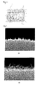
- FIG. 1 shows an image of a cross section of a surface-coated member 1 including a coating layer 3 by a transmission electron microscopic (TEM) photograph.
- FIG. 2 shows scanning electron microscope (SEM) photographs of the peripheries of the interlayers of cross sections of coating layers 3 and FIG. 2 (a) shows a member of the invention and FIG. 2 (b) shows a member for comparison.
- FIG. 3 shows an image of a main part of a cross-section of the coating layer 3 by a field emission-transmission electron microscopic (FE-TEM) photograph.
- FE-TEM field emission-transmission electron microscopic
- a surface-coated member 1 according to one embodiment of the invention is, as shown in Figs. 1 to 3 , provided with a substrate 2 and a coating layer 3 formed on the surface of the substrate 2.
- the coating layer 3 is formed by successively bonding a titanium carbonitride (TiCN) layer 4, an interlayer 5 containing titanium, aluminum, oxygen, and carbon, and an aluminum oxide (Al 2 O 3 ) layer 9 including an aluminum oxide (Al 2 O 3 ) crystal that is mainly the ⁇ -type crystal structure.
- the interlayer 5 has an average thickness of 0.5 to 30 nm and exists without disconnection. Attributed to that, the ⁇ -type Al 2 O 3 layer 9 on the interlayer 5 is formed substantially of a single ⁇ -type Al 2 O 3 and moreover the interlayer 5 is thin, and therefore, even when oxygen with low hardness is contained, peeling from the interlayer 5 can be suppressed.
- the interlayer 5 containing titanium, aluminum, oxygen, and carbon does not exist, the existence ratio of Al 2 O 3 with the ⁇ -type crystal structure is decreased because of production of Al 2 O 3 with the ⁇ -type crystal structure in the ⁇ -type Al 2 O 3 layer 9 thereon and therefore hardness of the Al 2 O 3 layer is decreased.
- the average thickness of the interlayer 5 is smaller than 0.5 nm, it is difficult to form the interlayer 5 without disconnection and when the interlayer 5 is disconnected, the Al 2 O 3 with the ⁇ -type crystal structure is formed in the ⁇ -type Al 2 O 3 layer 9 at the disconnected point.
- the interlayer 5 containing oxygen and having low hardness tends to be peeled easily due to the effect of the stress generated between the TiCN layer 4 and the ⁇ -type Al 2 O 3 layer 9.
- the thickness of the interlayer 5 can be measured by observation of a transmission electron microscopic (TEM) photograph of a cross section of the surface-coated member 1 including the coating layer 3.
- TEM transmission electron microscopic
- the atom types composing the interlayer 5 and the composition ratio can be measured by existence determination and quantitative analysis of elements with Energy Dispersive spectroscopy (EDS) and electron energy-loss spectroscopy (EELS) by using the transmission electron microscope (TEM).
- EDS Energy Dispersive spectroscopy
- EELS electron energy-loss spectroscopy
- the content of oxygen in the center of the interlayer 5 in the thickness direction is 15 to 40% by atom is preferable since Al 2 O 3 with almost entirely ⁇ -type crystal structure can be stably produced without partial production of Al 2 O 3 crystal with ⁇ -type crystal structure in the aluminum oxide (Al 2 O 3 ) layer 9.
- the x-ray diffraction measurement method of the present invention is carried out by using Cu-K ⁇ ray generated by using Cu as a bulb for x-ray.
- K ⁇ removal is carried out for accurate measurement of the peak position.
- Other measurement conditions are based on the conditions of a general x-ray diffraction method.
- ⁇ a(116) appears at a lower angle than ⁇ a0(116) (57.52°) and it is preferable since the ⁇ -type aluminum oxide crystal is strained in a specified direction to optimize the distribution of the residual stress and the hardness and strength of the Al 2 O 3 layer 9 can be improved and both of the wear resistance and the fracture resistance of the ⁇ -type Al 2 O 3 layer 9 can be improved.
- the surface-coated member 1 of this embodiment can be provided with improved strength and hardness of the ⁇ -type Al 2 O 3 layer 9 and improved fracture resistance and wear resistance.
- appearance of ⁇ a(116) in the higher angle side by 31.8° to 31.9° than ⁇ a(012) is preferable since the state of the residual stress applied to the ⁇ -type Al 2 O 3 crystal can be optimized and decrease of the fracture resistance of the ⁇ -type Al 2 O 3 layer 9 due to excess increase of the residual stress can be prevented.
- appearance of ⁇ a(104) , ⁇ a(110) , ⁇ a(113) , and ⁇ a(024) in the higher angle side of ⁇ a0(104) , ⁇ a0(110) , ⁇ a0(113) , and ⁇ a0(024) is preferable since the strength of Al 2 O 3 crystal can be improved and the fracture resistance of the ⁇ -type Al 2 O 3 layer can be improved.
- the content of titanium atom in the center of the interlayer 5 in the thickness direction is preferably 20 to 40% by atom in the entire amount of all elements detected by the composition analysis and the content of aluminum atom is preferably 5 to 15% by atom since the intermediate composition between the titanium carbonitride layer 4 and the ⁇ -type Al 2 O 3 layer 9 can be obtained to achieve firm bonding.
- the content of oxygen atom in the center of the interlayer 5 in the thickness direction is preferable to be 25 to 40% by atom in the entire amount of all elements detected by the composition analysis since the hardness and strength of the interlayer 5 can be improved and breakage easily caused by strong impact can be suppressed and good adhesiveness can be maintained.
- the TiCN layer 4 formed immediately under the interlayer 5 may be a TiCN layer made of granular crystals or a TiCN layer made of columnar crystals; however if the TiCN layer 4 is composed of columnar crystals, the toughness of the entire coating layer 3 is increased and thus fracture and chipping of the coating layer 3 can be suppressed.
- the interlayer 5 positioned in the interface between the TiCN layer 4 and the ⁇ -type Al 2 O 3 layer 9 can be formed by supplying only raw source gases containing both of titanium element of the TiCN layer 4 and aluminum element of the ⁇ -type Al 2 O 3 layer 9 and causing no chemical reaction and depositing and leaving a portion of the raw source gases on the surface of the coating layer during the coating formation (before the formation of the ⁇ -type Al 2 O 3 layer 9) to form an extremely thin and disconnected interlayer 5.
- At least one layer that is, another Ti-type coating layer, selected from a group consisting of a titanium nitride layer, a titanium carbide layer, a titanium oxycarbonitride layer, a titanium oxycarbide layer, and a titanium oxynitride layer between the TiCN layer 4 and the substrate 2, or on the ⁇ -type Al 2 O 3 layer 9.
- another Ti-type coating layer selected from a group consisting of a titanium nitride layer, a titanium carbide layer, a titanium oxycarbonitride layer, a titanium oxycarbide layer, and a titanium oxynitride layer between the TiCN layer 4 and the substrate 2, or on the ⁇ -type Al 2 O 3 layer 9.
- the substrate 2 of the surface-coated member 1 to be used preferably may be cemented carbides obtained by bonding tungsten carbide (WC) and a hard phase of at least one kind selected from a group consisting of carbides, nitrides, and carbonitrides of Group IV, V, and VI metals of a period chart of the elements with a bonding phase containing ferrous metals such as cobalt (Co) and/or nickel (Ni); Ti-based cermets, and ceramics such as Si 3 N 4 , Al 2 O 3 , diamond, cubic boron nitride (cBN), etc.
- WC tungsten carbide
- a hard phase of at least one kind selected from a group consisting of carbides, nitrides, and carbonitrides of Group IV, V, and VI metals of a period chart of the elements with a bonding phase containing ferrous metals such as cobalt (Co) and/or nickel (Ni); Ti-based cermets, and ceramics such
- the substrate 2 is preferable to be a cemented carbide or a cermet in terms of the fracture resistance and wear resistance. Further, as usage, the substrate 2 may be a metal such as carbon steel, a high-speed steel, an alloy steel, etc.
- the surface-coated member 1 with the above-mentioned configuration can be used for various applications such as sliding parts, wear resistant parts such as sliding parts and dies, drilling tools, knives, impact resistant parts, etc. other than cutting tools.
- the surface-coated member 1 is used in the cutting processing state that a cutting edge formed in a crossing part of a rake face and a flank face is attached to an object to be cut, and the above-mentioned excellent effects can be caused.
- the surface-coated member 1 has excellent mechanical reliability.
- the cutting tool in a severe cutting condition that high impact is applied to the cutting edge, for example, a heavy intermittent cutting of metals in which highly hard particles are dispersed such as gray cast iron (FC material) and ductile cast iron (FCD material) as a work material, the cutting tool shows an excellent cutting property as compared with a conventional cutting tool.
- FC material gray cast iron
- FCD material ductile cast iron
- the cutting tool shows an excellent cutting property. No need to say, in the cutting process of steels, the cutting tool also shows excellent fracture resistance and wear resistance as compared with a conventional cutting tool.
- a metal powder, a carbon powder, etc. are properly added to an inorganic powder such as metal carbides, nitrides, carbonitrides, oxides, etc. that can be formed by firing the above-mentioned substrate and the mixture is mixed and the resultant mixture is formed in a prescribed tool shape by a conventional molding method such as press-molding, casting, extrusion molding, cold isostatic pressing, etc. Thereafter, the obtained formed body is fired in vacuum or non-oxidizing atmosphere to produce the above-mentioned substrate 2 of a hard alloy. Based on the necessity, the surface of the substrate 2 is subjected to polishing processing or horning processing for edge parts.
- an inorganic powder such as metal carbides, nitrides, carbonitrides, oxides, etc.
- a coating layer 3 is formed by chemical vapor deposition (CVD) method on the surface of the obtained substrate 2.
- a titanium nitride (TiN) layer is formed as an undercoat layer 7 directly on the substrate 2 if desired.
- a gas mixture containing 0.5 to 10% by volume of titanium tetrachloride (TiCl 4 ) gas, 10 to 60% by volume of nitrogen (N 2 ) gas, and balance hydrogen (H 2 ) gas is used as a mixed gas composition and the coating formation temperature and pressure are desired to be 800 to 940°C (in the chamber) and 8 to 50 kPa.
- TiCN titanium carbonitride
- One example of coating formation condition of the TiCN layer 4 includes a condition that a gas mixture containing 0.5 to 10% by volume of titanium tetrachloride (TiCl 4 ) gas, 10 to 60% by volume of nitrogen (N 2 ) gas, 0.1 to 3.0% by volume of acetonitrile (CH 3 CN) gas, and balance hydrogen (H 2 ) gas is used as a mixed gas composition: the coating formation temperature is 780 to 880°C (in the chamber): and the pressure is 5 to 25 kPa and a so-called MT-TiCN layer composed of columnar crystals is formed. Accordingly, the fracture resistance of the coating layer 3 can be improved.
- TiCl 4 titanium tetrachloride
- N 2 nitrogen
- CH 3 CN acetonitrile
- H 2 hydrogen
- the TiCN layer 4 is no need to have a single structure formed by a single condition for the entire layer and the coating formation condition can be changed in the middle.
- the coating formation condition can be changed to a condition that a gas mixture containing 0.1 to 3% by volume of titanium tetrachloride (TiCl 4 ) gas, 0.1 to 10% by volume of methane (CH 4 ) gas or acetonitrile (CH 3 CN) gas, 0 to 15% by volume of nitrogen (N 2 ) gas, and balance hydrogen (H 2 ) gas is used: the coating formation temperature is 950 to 1100°C: and the pressure is 5 to 40 kPa to form HT-TiCN layer composed of granular crystals.
- TiCl 4 titanium tetrachloride
- CH 4 methane
- CH 3 CN acetonitrile
- N 2 nitrogen
- H 2 hydrogen
- the interlayer 5 is to be formed on the upper layer of the TiCN layer 4.
- the gas mixture to be used is a gas mixture containing 0.5 to 10% by volume of titanium tetrachloride (TiCl 4 ) gas and balance hydrogen (H 2 ) gas as a mixed gas composition.
- the gas mixture is introduced into the reaction chamber and the temperature in the chamber is set at 950 to 1100°C and the pressure is set to at 5 to 40 kPa (titanium conversion step: b-1 step).
- This step is effective to cause corrosion on the surface of the TiCN layer 4 during the process of decomposing the TiCl 4 gas serving as a treatment gas, and to form micro-recessions and projections in the surface of the TiCN layer 4 by the etching effect of the compound. Therefore, the adhesiveness can be further improved due to the anchor effect of the micro-recessions and projections.
- nitrogen (N 2 ) or a noble gas such as argon (Ar) is led by using carbon dioxide (CO 2 ) as a carrier gas to oxidize the surface of the base to be the interlayer 5 (b-2 step: oxidation treatment step). Consequently, the surface of the coating layer including the base for forming the interlayer 5 during the coating formation is oxidized to a proper but not excess extent.
- the condition of the gas mixture at that time is use of a gas mixture containing 0.5 to 4.0% by volume of carbon dioxide (CO 2 ) gas and balance of nitrogen (N 2 ) gas.
- the gas mixture is introduced into the reaction chamber and the temperature in the chamber is set at 950 to 1100°C and the pressure is set to at 5 to 40 kPa to oxidize the surface of the TiCN layer 4 containing the base to be the interlayer 5.
- the b-1 step titanium conversion step
- the gas mixture condition for the coating formation in the next b-2 step oxygen step
- the gas mixture is introduced into the reaction chamber and the temperature in the chamber is set at 950 to 1100°C and the pressure is set to at 5 to 40 kPa to form the interlayer 5 with a thickness as extremely thin as 0.5 to 5 nm.
- AlCl 3 aluminum chloride
- b-3 step: aluminum conversion step aluminum conversion step
- Al 2 O 3 layer described below on the surface of the interlayer oxidized in the b-2 step.
- the coating formation condition is that a gas mixture containing 0.5 to 5.0% by volume of aluminum trichloride (AlCl 3 ) gas and balance hydrogen (H 2 ) gas is used as a mixed gas composition and the temperature and pressure are set to be 950 to 1100°C and 5 to 40 kPa in the chamber.
- the b-3 step can be replaced with the c step, which is a coating formation step of the ⁇ -type Al 2 O 3 layer 9 described below, and therefore may be omitted; however in order to produce the nuclei of Al 2 O 3 crystals in the ⁇ -type crystal structure which is a base for forming the ⁇ -type Al 2 O 3 layer 9 and heighten the adhesion between the Al 2 O 3 layer 9 and the interlayer 5, the b-3 step is better to be carried out.
- the interlayer 5 is a reformed layer of the TiCN layer 4 produced by etching of the surface part of the TiCN layer 4 and successively oxidizing the layer.
- the interlayer 5 is formed by the method involving such steps by a method for forming the interlayer 5 by a general chemical reaction by introducing raw source gases, at first, nuclei of the formed interlayer 5 are dispersedly formed and the nuclei are gradually increased and deposited and therefore, it is difficult to form the interlayer 5 with a thickness as extremely thin as 30 nm without disconnection.
- the interlayer 5 is controlled by oxidation of the surface of the coating layer during the coating formation.
- H 2 hydrogen (H 2 ) to be used generally as a carrier gas for the CVD method
- the surface of the coating layer is prevented from excess oxidation due to the reaction with carbon dioxide (CO 2 ) for oxidation and the interlayer 5 with an extremely thin thickness can be formed without disconnection (refer to FIG. 2A ).
- CO carbon monoxide
- the surface of the coating layer cannot be oxidized sufficiently, and ⁇ -type crystals tend to be formed in the ⁇ -type Al 2 O 3 layer 9.
- a concrete example of the coating formation condition is desirably that a gas mixture containing 0.5 to 5.0% by volume of aluminum trichloride (AlCl 3 ) gas, 0.5 to 3.5% by volume of hydrogen chloride (HCl) gas, 0.5 to 5.0% by volume of carbon dioxide (CO 2 ) gas, 0 to 0.5% by volume of hydrogen sulfide (H 2 S) gas and balance hydrogen (H 2 ) gas is used and the coating formation temperature and pressure are set to be 950 to 1100°C and 5 to 10 kPa.
- AlCl 3 aluminum trichloride
- HCl hydrogen chloride
- CO 2 carbon dioxide
- H 2 S hydrogen sulfide
- H 2 S hydrogen sulfide
- a lower part region of the ⁇ -type Al 2 O 3 layer 9 is formed in the coating formation condition of a lowered flow rate of HCl gas and thereafter, an upper part region of the ⁇ -type Al 2 O 3 layer 9 is formed in the coating formation condition that the HCl gas flow rate is increased higher than that of the former condition. That is, the ⁇ -type Al 2 O 3 layer 9 is desired to have two kinds of regions different in the crystal structure of the ⁇ -type Al 2 O 3 layer 9. Accordingly, the nuclei of fine crystals of ⁇ -type Al 2 O 3 are formed in the initial period of the coating formation.
- the residual stress applied on the ⁇ -type Al 2 O 3 existing in the interface with the interlayer 5 can be dispersed to heighten the adhesion in the interface. Further, formation of the nuclei of fine crystals of the ⁇ -type Al 2 O 3 causes an effect of making the crystals of the entire ⁇ -type Al 2 O 3 layer 9 be fine and increasing the hardness of the ⁇ -type Al 2 O 3 layer 9.
- a titanium nitride layer is formed as a surface layer 10 on the upper layer of the ⁇ -type Al 2 O 3 layer 9.
- the coating formation condition of the TiN layer is desired to that a gas mixture containing 0.1 to 10% by volume of titanium tetrachloride (TiCl 4 ) gas, 10 to 60% by volume of nitrogen (N 2 ) gas, and balance hydrogen (H 2 ) gas is used as a gas mixture composition and the temperature and the pressure in the reaction chamber are set to be 960 to 1100°C and 10 to 85 kPa.
- At least the cutting edge part of the surface of the coating layer 3 is subjected to polishing processing.
- the polishing processing makes the cutting edge part smooth and suppresses deposition of weld and gives a tool further excellent in the fracture resistance.
- the molded body was subjected to de-binder treatment and fired at 1400°C for 1 hour in vacuum of 0.5 to 100 Pa to produce a cemented carbide. Further, the produced cemented carbide was subjected to edge-formation treatment (R-horning) for the rake face by brushing treatment.
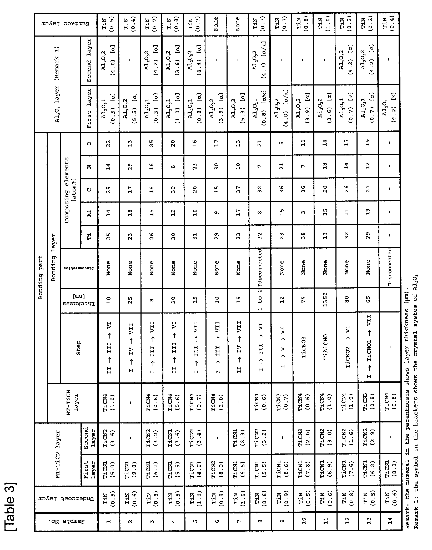
- each coating layer 3 was formed by CVD method in the coating formation conditions and layer structure as shown in Tables 1 to 4.
- the surface of each coating layer 3 was subjected to brushing treatment for 30 seconds from the rake face side to produce surface-coated cutting tools of sample Nos. 1 to 29.
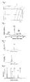
- Figs. 4 and 5 show the peak charts of the x-ray diffraction intensity with a solid line for the sample No. 1 and FIG. 6 shows the peak chart for the sample No. 15.
- polishing processing by machine polishing and ion milling was carried out for observing each coating layer 3 having the layered structure shown in Tables 3 and 4 by using the transmission electron microscope (TEM) and a cross section was exposed.
- the micro structure state of each layer observed in approximately perpendicular direction to the cross section of each layer was observed and the thickness of the layer was measured.
- the atom types existing in the center of the interlayer were confirmed and the composition was analyzed by energy dispersive spectroscopy (EDS) or electron energy-loss spectroscopy (EELS).
- EDS energy dispersive spectroscopy
- EELS electron energy-loss spectroscopy
- the respective types of coating layers 3 with the layer structures were formed for the cemented carbides subjected to the edge treatment (R-honing) of Example 1 in the coating formation condition by the CVD method as shown in Table 1 and Table 7.
- the obtained samples (30 to 33) were evaluated in the same manner as Example 1. The results are shown in Table 8 to 10.
Abstract
Description
- The present invention relates to a surface-coated member obtained by forming a coating layer on the surface of a substrate and a cutting tool using the member.
- Conventionally, a surface-coated cutting tool comprising a monolayer or multilayer coating layer on the surface of a substrate of a cemented carbide, a cermet, a ceramic, or the like has been known as a cutting tool to be used widely in cutting processing of metals, printed circuit boards, etc. As the coating layer, those composed by layering a titanium carbide (TiC) layer, a titanium nitride (TiN) layer, a titanium carbonitride (TiCN) layer, an aluminum oxide (Al2O3) layer, and so on have been often used.
- Having a good oxidation resistance, the Al2O3 layer among these coating layers exhibits high abrasion resistance and high capability in the processing condition in which the temperature of a cutting edge tends to be high temperature at the time of cutting, e.g., even in processing condition for processing of materials such as cast iron and alloyed steel which are hard to be cut or for high speed cutting. Especially, an Al2O3 layer made of Al2O3 with α-type crystal structure (hereinafter, referred to as α-type Al2O3 layer for short) has been conventionally used in a wide range since it has high hardness and high oxidation resistance.
- For example,
Patent Document 1 discloses a surface-coated cutting tool having an Al2O3 layer of Al2O3 having orientation with values of I(030)/I(104) and I(012)/I(030) greater than 1, respectively, where the peak intensity of a (hkl) plane of Al2O3 of mainly α-type crystal by x-ray diffraction analysis is defined as I(hkl) and describes that the fracture resistance of the Al2O3 layer can be improved. - Further,
Patent Document 2 discloses a coated article with an texture coefficient of the (012) plane of α-type Al2O3 layer (TC: the index expressing the maximum peak intensity of diffraction peaks attributed to the (012) plane among the entire diffraction peaks of the α-type Al2O3 crystal) higher than 1.3 and describes that the particles of the Al2O3 layer can be made fine and the hardness and strength of the Al2O3 layer can be improved. - On the other hand,
Patent Document 3 discloses a coated tool having an Al2O3 layer of Al2O3 with κ-type crystal structure and the surface separation of 1.43A (namely, diffraction angle 2θ is 65.18°) of the highest intense peak with the highest x-ray diffraction intensity and describes that the adhesion of the Al2O3 layer can be improved. - Patent Document 1: Japanese Patent Laid Open Publication No.
H07-108405 - Patent Document 2: Japanese Patent Laid Open Publication No.
H06-316758 - Patent Document 3: Japanese Patent Laid Open Publication No.
H11-77407 - However, along with today's high efficiency of the cutting processing, a cutting tool tends to be used in further severe cutting conditions. In such severe cutting conditions, with respect to the α-type Al2O3 layer in
Patent Document 1 andPatent Document 2 in which the oriental direction of the entire crystal with the peak intensity of the diffraction peak is merely controlled, the Al2O3 layer is insufficient in the adhesion and thus cannot withstand the severe cutting conditions to sometimes cause separation in the boundary between the Al2O3 layer and a layer beneath. - Further, as described in
Patent Document 3, if the Al2O3 layer is made to have the κ-type crystal structure, the adhesion to the layer beneath can be reinforced; however Al2O3 with the κ-type crystal structure has lower hardness than Al2O3 with α-type crystal structure and therefore, there is a problem that progression of abrasion is rapid. - Accordingly, the present invention has been made in view of the above-mentioned problems and an object of the invention is to provide a surface-coated member having a coating layer with high adhesion and high wear resistance.
- A surface-coated member of the present invention is provided with a coating layer having a layered body formed by successively bonding a titanium carbonitride (TiCN) layer, an interlayer containing titanium, aluminum, carbon, and oxygen, having an average thickness of 0.5 to 30 nm, and existing without disconnection, and an aluminum oxide (Al2O3) layer including an aluminum oxide (Al2O3) with the α-type crystal structure on the surface of a substrate.
- Herein, in the above-mentioned configuration, that the oxygen content in the center of the interlayer in the thickness direction is 15 to 40% by atom is preferable since almost entirely the Al2O3 crystal with the α-type crystal structure is stably produced without partial production of Al2O3 crystal with κ-type crystal structure in the aluminum oxide (Al2O3) layer.
- Further, in the above-mentioned configuration, with respect to the diffraction peaks of x-ray diffraction analysis for the surface-coated member, it is found that in the case where θt is defined as the 2θ value of a diffraction peak attributed to the (200) plane of TiCN; θt0 is defined as the 2θ value of a diffraction peak attributed to the (200) plane of TiCN described in JCPDS card; θa(hkl) is defined as the 2θ value of a diffraction peak attributed to the (012), (104), (110), and (113) planes of the α-type crystal structure of Al2O3 (wherein, (hkl) is one of (012), (104), (110), and (113)); and θa0(hkl) is defined as the 2θ value of a diffraction peak attributed to the (012), (104), (110), and (113) planes of the α-type crystal structure of Al2O3 described in JCPDS card (wherein, (hkl) is one of (012), (104), (110), and (113)); an effect of suppressing the crystal strain and preventing peeling between the titanium carbonitride (TiCN) layer and the α-type Al2O3 layer is caused by controlling the difference of Δθz(hkl) (= θt - θa(hkl) (wherein (hkl) is one of (012), (104), (110), and (113)) between the difference Δθt (= θt - θt0) of θt and θt0 and the difference of Δθa(hkl) (= θa(hkl) - θa0(hkl)) of θa(hkl) and θa0(hkl) of (012), (104), (110), and (113) planes in a range of -0.2° to 0.2° for all cases.
- Furthermore, in the case where Δθz(012) for the (012) plane is in a range of -0.2° to 0.2°, the adhesion between the titanium carbonitride layer and the α-type aluminum oxide layer is further improved.
- Herein, with respect to the α-type aluminum oxide layer, in the case where the difference of the θa(12) and the θa0(12) is corrected to be zero, θa(116) appears at a lower angle than θa0(116) and it is preferable since the α-type aluminum oxide crystal is strained in a specified direction to optimize the distribution of the residual stress and the hardness and strength of the aluminum oxide layer can be improved and both of the abrasion resistance and the fracture resistance of the α-type aluminum oxide layer can be improved.
- In this case, appearance of the θa(116) in the higher angle side by 31.8° to 31.9° than the θa(012) is preferable since the residual stress applied to the α-type aluminum oxide crystal can be optimized and decrease of the fracture resistance of the α-type aluminum oxide layer due to excess increase of the residual stress can be prevented.
- Further, appearance of θa(104), θa(110), θa(113), and θa(024) in the higher angle side of θa0(104), θa0(110), θa0(113), and θa0(024) is preferable since the strength of aluminum oxide particles can be improved and the fracture resistance of the α-type aluminum oxide layer can be improved.
- Moreover, a surface-coated cutting tool of the present invention is provided with the aforementioned surface-coated member. With such a configuration, a cutting tool is good in the wear resistance and fracture resistance and has a long tool life can be provided.
- The surface-coated member of the present invention comprises the interlayer containing titanium, aluminum, carbon, and oxygen and existing without disconnection, so that the aluminum oxide layer on the upper part of the interlayer is to be an almost all α-type Al2O3 layer and also the average thickness of the interlayer is as thin as 0.5 to 30 nm, and therefore, peeling of the aluminum oxide layer from the interlayer part due to oxygen content can be suppressed.
-
FIG. 1 shows an image of a cross section of a surface-coatedmember 1 including acoating layer 3 by a transmission electron microscopic (TEM) photograph.FIG. 2 shows scanning electron microscope (SEM) photographs of the peripheries of the interlayers of cross sections ofcoating layers 3 andFIG. 2 (a) shows a member of the invention andFIG. 2 (b) shows a member for comparison.FIG. 3 shows an image of a main part of a cross-section of thecoating layer 3 by a field emission-transmission electron microscopic (FE-TEM) photograph. - A surface-coated
member 1 according to one embodiment of the invention is, as shown inFigs. 1 to 3 , provided with asubstrate 2 and acoating layer 3 formed on the surface of thesubstrate 2. Thecoating layer 3 is formed by successively bonding a titanium carbonitride (TiCN)layer 4, aninterlayer 5 containing titanium, aluminum, oxygen, and carbon, and an aluminum oxide (Al2O3)layer 9 including an aluminum oxide (Al2O3) crystal that is mainly the α-type crystal structure. - Herein, the
interlayer 5 has an average thickness of 0.5 to 30 nm and exists without disconnection. Attributed to that, the α-type Al2O3 layer 9 on theinterlayer 5 is formed substantially of a single α-type Al2O3 and moreover theinterlayer 5 is thin, and therefore, even when oxygen with low hardness is contained, peeling from theinterlayer 5 can be suppressed. - In other words, if the
interlayer 5 containing titanium, aluminum, oxygen, and carbon does not exist, the existence ratio of Al2O3 with the α-type crystal structure is decreased because of production of Al2O3 with the κ-type crystal structure in the α-type Al2O3 layer 9 thereon and therefore hardness of the Al2O3 layer is decreased. Further, if the average thickness of theinterlayer 5 is smaller than 0.5 nm, it is difficult to form theinterlayer 5 without disconnection and when theinterlayer 5 is disconnected, the Al2O3 with the κ-type crystal structure is formed in the α-type Al2O3 layer 9 at the disconnected point. Furthermore, if the thickness of theinterlayer 5 is smaller than 30 nm, theinterlayer 5 containing oxygen and having low hardness tends to be peeled easily due to the effect of the stress generated between theTiCN layer 4 and the α-type Al2O3 layer 9. - The thickness of the
interlayer 5 can be measured by observation of a transmission electron microscopic (TEM) photograph of a cross section of the surface-coatedmember 1 including thecoating layer 3. The atom types composing theinterlayer 5 and the composition ratio can be measured by existence determination and quantitative analysis of elements with Energy Dispersive spectroscopy (EDS) and electron energy-loss spectroscopy (EELS) by using the transmission electron microscope (TEM). - The content of oxygen in the center of the
interlayer 5 in the thickness direction is 15 to 40% by atom is preferable since Al2O3 with almost entirely α-type crystal structure can be stably produced without partial production of Al2O3 crystal with κ-type crystal structure in the aluminum oxide (Al2O3)layer 9. - Further, with respect to diffraction peaks of the
hard layer 3 obtained by X-ray diffraction analysis, θt is defined as the 2θ value of a diffraction peak attributed to the (200) plane of TiCN; θt0 is defined as the 2θ value of a diffraction peak attributed to the (200) plane described in JCPDS card (Powder x-ray diffraction data file of chemical substances published by Joint Committee on Powder Diffraction Standards); θa(hkl) is defined as the 2θ value of a diffraction peak attributed to the (012), (104), (110), and (113) planes of the α-type crystal structure of Al2O3, where (hkl) is one of (012), (104), (110), and (113), respectively; and θa0(hkl) is defined as the 2θ value of a diffraction peak attributed to the (012), (104), (110), and (113) planes of the α-type crystal structure of Al2O3 described in JCPDS card where, (hkl) is one of (012), (104), (110), and (113)), respectively. If the difference of Δθz(hkl) (= θt - θa(hkl), where (hkl) is one of (012), (104), (110), and (113)) between the difference Δθt (= θt - θt0) of θt and θt0 and the difference of Δθa(hkl) (= θa(hkl) - θa0(hkl)) of θa(hkl) and θa0(hkl) of (012), (104), (110), and (113) planes is all in a range of -0.2° to 0.2°, no peeling occurs in the interface of theTiCN layer 4 and the α-type Al2O3 layer 9 and thus the adhesion of the α-type Al2O3 layer 9 is consequently improved. - Further, it is also found that if Δθz(012) of the (012) plane of the α-type Al2O3 is in a range of -0.2° to 0°, the adhesion between the
TiCN layer 4 and the α-type Al2O3 layer 9 can be further improved. - In addition, the x-ray diffraction measurement method of the present invention is carried out by using Cu-Kα ray generated by using Cu as a bulb for x-ray. To specify the position of the diffraction angle 2θ, Kα removal is carried out for accurate measurement of the peak position. Other measurement conditions are based on the conditions of a general x-ray diffraction method.
- Herein, according to this embodiment, when the difference between θa(112) and θa0(112) is corrected to be zero for the α-type Al2O3 layer 9, θa(116) appears at a lower angle than θa0(116) (57.52°) and it is preferable since the α-type aluminum oxide crystal is strained in a specified direction to optimize the distribution of the residual stress and the hardness and strength of the Al2O3 layer 9 can be improved and both of the wear resistance and the fracture resistance of the α-type Al2O3 layer 9 can be improved.
- That is, in an α-type Al2O3 layer formed by a conventional CVD method, tensile stress is caused, the α-type Al2O3 layer including the crystal structure with 2θ(116) shifted to the higher angle side than 2θ0(116), whereas in the α-type Al2O3 layer 9 of the surface-coated
member 1 according to this embodiment, the stress in the different direction from that of the stress applied to the (116) plane of the α-Al2O3 layer formed by the conventional CVD method is applied to the (116) plane and the tensile stress is relieved, the α-type Al2O3 layer 9 including a crystal structure with 2θ(116) shifted to the lower angle side than 2θ0(116). With such a configuration, the surface-coatedmember 1 of this embodiment can be provided with improved strength and hardness of the α-type Al2O3 layer 9 and improved fracture resistance and wear resistance. - In this case, appearance of θa(116) in the higher angle side by 31.8° to 31.9° than θa(012) is preferable since the state of the residual stress applied to the α-type Al2O3 crystal can be optimized and decrease of the fracture resistance of the α-type Al2O3 layer 9 due to excess increase of the residual stress can be prevented.
- The reason why the peak of the (012) plane among the peaks of α-type Al2O3 layer 9 is used as a reference in the case of correction of the measurement data of the respective planes because the peak is positioned at the lowest angle side. That is, it is because the peak shift is slight even if strains are generated in the lattice.
- Further, appearance of θa(104), θa(110), θa(113), and θa(024) in the higher angle side of θa0(104), θa0(110), θa0(113), and θa0(024) is preferable since the strength of Al2O3 crystal can be improved and the fracture resistance of the α-type Al2O3 layer can be improved.
- The content of titanium atom in the center of the
interlayer 5 in the thickness direction is preferably 20 to 40% by atom in the entire amount of all elements detected by the composition analysis and the content of aluminum atom is preferably 5 to 15% by atom since the intermediate composition between thetitanium carbonitride layer 4 and the α-type Al2O3 layer 9 can be obtained to achieve firm bonding. - Furthermore, the content of oxygen atom in the center of the
interlayer 5 in the thickness direction is preferable to be 25 to 40% by atom in the entire amount of all elements detected by the composition analysis since the hardness and strength of theinterlayer 5 can be improved and breakage easily caused by strong impact can be suppressed and good adhesiveness can be maintained. - The
TiCN layer 4 formed immediately under theinterlayer 5 may be a TiCN layer made of granular crystals or a TiCN layer made of columnar crystals; however if theTiCN layer 4 is composed of columnar crystals, the toughness of theentire coating layer 3 is increased and thus fracture and chipping of thecoating layer 3 can be suppressed. - The
interlayer 5 positioned in the interface between theTiCN layer 4 and the α-type Al2O3 layer 9 can be formed by supplying only raw source gases containing both of titanium element of theTiCN layer 4 and aluminum element of the α-type Al2O3 layer 9 and causing no chemical reaction and depositing and leaving a portion of the raw source gases on the surface of the coating layer during the coating formation (before the formation of the α-type Al2O3 layer 9) to form an extremely thin anddisconnected interlayer 5. - Further, it is preferable to form at least one layer, that is, another Ti-type coating layer, selected from a group consisting of a titanium nitride layer, a titanium carbide layer, a titanium oxycarbonitride layer, a titanium oxycarbide layer, and a titanium oxynitride layer between the
TiCN layer 4 and thesubstrate 2, or on the α-type Al2O3 layer 9. - The
substrate 2 of the surface-coatedmember 1 to be used preferably may be cemented carbides obtained by bonding tungsten carbide (WC) and a hard phase of at least one kind selected from a group consisting of carbides, nitrides, and carbonitrides of Group IV, V, and VI metals of a period chart of the elements with a bonding phase containing ferrous metals such as cobalt (Co) and/or nickel (Ni); Ti-based cermets, and ceramics such as Si3N4, Al2O3, diamond, cubic boron nitride (cBN), etc. Especially, if the surface-coatedmember 1 is used as a cutting tool, thesubstrate 2 is preferable to be a cemented carbide or a cermet in terms of the fracture resistance and wear resistance. Further, as usage, thesubstrate 2 may be a metal such as carbon steel, a high-speed steel, an alloy steel, etc. - Moreover, the surface-coated
member 1 with the above-mentioned configuration can be used for various applications such as sliding parts, wear resistant parts such as sliding parts and dies, drilling tools, knives, impact resistant parts, etc. other than cutting tools. For example, in the case of use of the member for a cutting tool, the surface-coatedmember 1 is used in the cutting processing state that a cutting edge formed in a crossing part of a rake face and a flank face is attached to an object to be cut, and the above-mentioned excellent effects can be caused. Furthermore, even in the case of other uses, the surface-coatedmember 1 has excellent mechanical reliability. - Particularly, with respect to the application for cutting tools, in a severe cutting condition that high impact is applied to the cutting edge, for example, a heavy intermittent cutting of metals in which highly hard particles are dispersed such as gray cast iron (FC material) and ductile cast iron (FCD material) as a work material, the cutting tool shows an excellent cutting property as compared with a conventional cutting tool. In other words, even if a high impact is abruptly applied to the
coating layer 3, since the α-type Al2O3 layer 9 is bonded firmly to thetitanium carbonitride layer 4 through theinterlayer 5 in thecoating layer 3 of this embodiment, chipping or fracture of thecoating layer 3 can be suppressed. Further, in continuous cutting condition that the depth of cutting is fluctuated during the cutting such as cutting of pouring gates existing in cast iron or burrs of casting dies and also in the combinated cutting condition of continuous cutting and intermittent cutting in combination, the cutting tool shows an excellent cutting property. No need to say, in the cutting process of steels, the cutting tool also shows excellent fracture resistance and wear resistance as compared with a conventional cutting tool. - One embodiment of a method for producing the above-mentioned cutting tool is descried.
- At first, a metal powder, a carbon powder, etc. are properly added to an inorganic powder such as metal carbides, nitrides, carbonitrides, oxides, etc. that can be formed by firing the above-mentioned substrate and the mixture is mixed and the resultant mixture is formed in a prescribed tool shape by a conventional molding method such as press-molding, casting, extrusion molding, cold isostatic pressing, etc. Thereafter, the obtained formed body is fired in vacuum or non-oxidizing atmosphere to produce the above-mentioned
substrate 2 of a hard alloy. Based on the necessity, the surface of thesubstrate 2 is subjected to polishing processing or horning processing for edge parts. - Next, a
coating layer 3 is formed by chemical vapor deposition (CVD) method on the surface of the obtainedsubstrate 2.
At first, a titanium nitride (TiN) layer is formed as an undercoat layer 7 directly on thesubstrate 2 if desired. As one example of the coating (formation) condition of the titanium nitride layer as the undercoat layer 7, a gas mixture containing 0.5 to 10% by volume of titanium tetrachloride (TiCl4) gas, 10 to 60% by volume of nitrogen (N2) gas, and balance hydrogen (H2) gas is used as a mixed gas composition and the coating formation temperature and pressure are desired to be 800 to 940°C (in the chamber) and 8 to 50 kPa. - Next, a titanium carbonitride (TiCN)
layer 4 is formed on the upper layer of the undercoating layer 7 ("a" step). - One example of coating formation condition of the
TiCN layer 4 includes a condition that a gas mixture containing 0.5 to 10% by volume of titanium tetrachloride (TiCl4) gas, 10 to 60% by volume of nitrogen (N2) gas, 0.1 to 3.0% by volume of acetonitrile (CH3CN) gas, and balance hydrogen (H2) gas is used as a mixed gas composition: the coating formation temperature is 780 to 880°C (in the chamber): and the pressure is 5 to 25 kPa and a so-called MT-TiCN layer composed of columnar crystals is formed. Accordingly, the fracture resistance of thecoating layer 3 can be improved. - Further, the
TiCN layer 4 is no need to have a single structure formed by a single condition for the entire layer and the coating formation condition can be changed in the middle. For example, in the middle of the coating formation in the above-mentioned condition, the coating formation condition can be changed to a condition that a gas mixture containing 0.1 to 3% by volume of titanium tetrachloride (TiCl4) gas, 0.1 to 10% by volume of methane (CH4) gas or acetonitrile (CH3CN) gas, 0 to 15% by volume of nitrogen (N2) gas, and balance hydrogen (H2) gas is used: the coating formation temperature is 950 to 1100°C: and the pressure is 5 to 40 kPa to form HT-TiCN layer composed of granular crystals. In such as manner, it is preferable to form a layered structure of the MT-TiCN layer composed of columnar crystals and HT-TiCN layer composed of granular crystals in terms of improvement of the adhesion between theTiCN layer 4 and the α-type Al2O3 layer 9. - Next, the
interlayer 5 is to be formed on the upper layer of theTiCN layer 4. - At first, only titanium chloride (TiCl4) is led or titanium chloride (TiCl4) and a reaction gas containing an oxygen source and a carbon source are led using hydrogen as a carrier gas to form a base to be the interlayer 5 (b-1 step: titanium-conversion step). Consequently, the surface of the
TiCN layer 4 is etched to be the base of theinterlayer 5. At that time, the gas mixture to be used is a gas mixture containing 0.5 to 10% by volume of titanium tetrachloride (TiCl4) gas and balance hydrogen (H2) gas as a mixed gas composition. The gas mixture is introduced into the reaction chamber and the temperature in the chamber is set at 950 to 1100°C and the pressure is set to at 5 to 40 kPa (titanium conversion step: b-1 step). - This step is effective to cause corrosion on the surface of the
TiCN layer 4 during the process of decomposing the TiCl4 gas serving as a treatment gas, and to form micro-recessions and projections in the surface of theTiCN layer 4 by the etching effect of the compound. Therefore, the adhesiveness can be further improved due to the anchor effect of the micro-recessions and projections. - Next, nitrogen (N2) or a noble gas such as argon (Ar) is led by using carbon dioxide (CO2) as a carrier gas to oxidize the surface of the base to be the interlayer 5 (b-2 step: oxidation treatment step). Consequently, the surface of the coating layer including the base for forming the
interlayer 5 during the coating formation is oxidized to a proper but not excess extent. The condition of the gas mixture at that time is use of a gas mixture containing 0.5 to 4.0% by volume of carbon dioxide (CO2) gas and balance of nitrogen (N2) gas. The gas mixture is introduced into the reaction chamber and the temperature in the chamber is set at 950 to 1100°C and the pressure is set to at 5 to 40 kPa to oxidize the surface of theTiCN layer 4 containing the base to be theinterlayer 5. - In the above-mentioned condition, the b-1 step (titanium conversion step) may be omitted and the gas mixture condition for the coating formation in the next b-2 step (oxidation step) may be changed to a gas mixture containing 0.1 to 0.5% by volume of carbon dioxide (CO2) gas and balance of nitrogen (N2) gas and the gas mixture is introduced into the reaction chamber and the temperature in the chamber is set at 950 to 1100°C and the pressure is set to at 5 to 40 kPa to form the
interlayer 5 with a thickness as extremely thin as 0.5 to 5 nm. - Thereafter, aluminum chloride (AlCl3) is led by using hydrogen as a carrier gas to carry out pretreatment (b-3 step: aluminum conversion step) for forming an Al2O3 layer described below on the surface of the interlayer oxidized in the b-2 step. Concretely one example of the coating formation condition is that a gas mixture containing 0.5 to 5.0% by volume of aluminum trichloride (AlCl3) gas and balance hydrogen (H2) gas is used as a mixed gas composition and the temperature and pressure are set to be 950 to 1100°C and 5 to 40 kPa in the chamber. Additionally, the b-3 step can be replaced with the c step, which is a coating formation step of the α-type Al2O3 layer 9 described below, and therefore may be omitted; however in order to produce the nuclei of Al2O3 crystals in the α-type crystal structure which is a base for forming the α-type Al2O3 layer 9 and heighten the adhesion between the Al2O3 layer 9 and the
interlayer 5, the b-3 step is better to be carried out. - As described above, the
interlayer 5 is a reformed layer of theTiCN layer 4 produced by etching of the surface part of theTiCN layer 4 and successively oxidizing the layer. - Formation of the
interlayer 5 by the method involving such steps makes it possible to form theinterlayer 5 with an extremely thin thickness without disconnection which causes an effect on the crystal growth of the α-type Al2O3 layer 9 to be formed directly on theinterlayer 5. That is, in a method for forming theinterlayer 5 by a general chemical reaction by introducing raw source gases, at first, nuclei of the formedinterlayer 5 are dispersedly formed and the nuclei are gradually increased and deposited and therefore, it is difficult to form theinterlayer 5 with a thickness as extremely thin as 30 nm without disconnection. According to the invention, theinterlayer 5 is controlled by oxidation of the surface of the coating layer during the coating formation. Herein, at the time of oxidation, hydrogen (H2) to be used generally as a carrier gas for the CVD method, carbon dioxide (CO2) is reacted for oxidation with hydrogen (H2) to produce water (H2 + CO2 = H2O + CO) and due to the produced water, the surface of the coating layer is reacted intensely to produce titanium oxide, which is abnormally grown and forms a coating (refer toFIG. 2B ). Therefore, according to the invention, in order to suppress the oxidation of the surface of the coating layer to an excess extent in the oxidation step, nitrogen (N2) or a noble gas is used instead of hydrogen (H2) as the carrier gas. Accordingly, the surface of the coating layer is prevented from excess oxidation due to the reaction with carbon dioxide (CO2) for oxidation and theinterlayer 5 with an extremely thin thickness can be formed without disconnection (refer toFIG. 2A ). In addition, in the case where carbon monoxide (CO) is used in place of carbon dioxide (CO2) for oxidation, the surface of the coating layer cannot be oxidized sufficiently, and κ-type crystals tend to be formed in the α-type Al2O3 layer 9. - Thereafter, successively, the α-type Al2O3 layer 9 is formed (c step). A concrete example of the coating formation condition is desirably that a gas mixture containing 0.5 to 5.0% by volume of aluminum trichloride (AlCl3) gas, 0.5 to 3.5% by volume of hydrogen chloride (HCl) gas, 0.5 to 5.0% by volume of carbon dioxide (CO2) gas, 0 to 0.5% by volume of hydrogen sulfide (H2S) gas and balance hydrogen (H2) gas is used and the coating formation temperature and pressure are set to be 950 to 1100°C and 5 to 10 kPa.
- Herein, for the α-type Al2O3 layer 9, a lower part region of the α-type Al2O3 layer 9 is formed in the coating formation condition of a lowered flow rate of HCl gas and thereafter, an upper part region of the α-type Al2O3 layer 9 is formed in the coating formation condition that the HCl gas flow rate is increased higher than that of the former condition. That is, the α-type Al2O3 layer 9 is desired to have two kinds of regions different in the crystal structure of the α-type Al2O3 layer 9. Accordingly, the nuclei of fine crystals of α-type Al2O3 are formed in the initial period of the coating formation. Therefore, the residual stress applied on the α-type Al2O3 existing in the interface with the
interlayer 5 can be dispersed to heighten the adhesion in the interface. Further, formation of the nuclei of fine crystals of the α-type Al2O3 causes an effect of making the crystals of the entire α-type Al2O3 layer 9 be fine and increasing the hardness of the α-type Al2O3 layer 9. - Furthermore, if desired, a titanium nitride layer is formed as a
surface layer 10 on the upper layer of the α-type Al2O3 layer 9. The coating formation condition of the TiN layer is desired to that a gas mixture containing 0.1 to 10% by volume of titanium tetrachloride (TiCl4) gas, 10 to 60% by volume of nitrogen (N2) gas, and balance hydrogen (H2) gas is used as a gas mixture composition and the temperature and the pressure in the reaction chamber are set to be 960 to 1100°C and 10 to 85 kPa. - If desired, at least the cutting edge part of the surface of the
coating layer 3 is subjected to polishing processing. The polishing processing makes the cutting edge part smooth and suppresses deposition of weld and gives a tool further excellent in the fracture resistance. - A mixture obtained by adding 6 wt.% of metal cobalt (Co) powder with an average particle diameter of 1.2 µm and 0.2 wt.% of tantalum carbide (TaC) powder were mixed with tungsten carbide (WC) powder with an average particle diameter of 1.5 µm was mixed and formed by press-forming to obtain a cutting tool shape (CNMA 120412). The molded body was subjected to de-binder treatment and fired at 1400°C for 1 hour in vacuum of 0.5 to 100 Pa to produce a cemented carbide. Further, the produced cemented carbide was subjected to edge-formation treatment (R-horning) for the rake face by brushing treatment.
- Next, with respect to the above-mentioned cemented carbide, the
respective coating layers 3 were formed by CVD method in the coating formation conditions and layer structure as shown in Tables 1 to 4. The surface of eachcoating layer 3 was subjected to brushing treatment for 30 seconds from the rake face side to produce surface-coated cutting tools of sample Nos. 1 to 29. -
[Table 1] Coating layer Gas mixture composition (% by volume) Temperature in furnace (°C) Pressure (kPa) Undercoat layer (TiN) TiC14:3.0,N2:33,H2: Balance 880 16 TiCN1 TiCl4:3.0,N2:33,CH3CN:0.4,H2: Balance 865 9 TiCN2 TiCl4:2.7,N2:23,CH3CN:0.9,H2: Balance 865 9 TiCN3 TiCl4:3.0,N2:3,CH3CN:1.0,H2: Balance 1000 20 TiCN4 TiCl4:3.5,N2:5,CH4:8,H2: Balance 1010 30 I Titanium conversion step 1 TiCl4:3.0,H2: Balance 1010 9 II Titanium conversion step 2 TiCl4:1.6,H2: Balance 1010 8 III Oxidation step 1 CO2:2.0,N2: Balance 1010 9 IV Oxidation step 2 CO2:1.7,Ar: Balance 1010 9 V Oxidation step 3 CO:2.0,Ar: Balance 1010 9 VIII Oxidation step 4 CO2:0.6,N2: Balance 1010 9 IX Oxidation step 5 CO2:0.9,N2: Balance 1010 9 VI Aluminum conversion step 1 AlCl3:1.8 H2: Balance 1010 9 VII Aluminum conversion step 2 AlCl3:2.2 H2: Balance 1010 7 TiCNO1 TiCl4:3.0,CH4:7.0,N2,:20,CO2:2.0,H2: Balance 1010 9 TiCNO2 TiCl4:1.5,CH4:3.4,N2,:27,CO2:1.0,H2: Balance 1010 10 TiCNO3 TiCl4:1.5,CH4:3.0,N2,:10,CO:1.5,H2: Balance 1010 10 TiAlCNO TiCl4:1.0,AlCl3:4.0,CH4:2.0,N2,:4.0,CO:1.5,H2: Balance 1010 10 Al2O3l AlCl3:1.5,HCl:1.0,CO2:4,H2: Balance 1005 9 Al2O3 AlCl3:1.5, HCl:2, CO2:4, H2S:0.3,H2: Balance 1005 9 Surface layer (TiN) TiCl4:3.0,N2:30,H2; Balance 1010 30 -
[Table 2] Coating layer Gas mixture composition (% by volume) Temperature in furnace (°C) Pressure (kPa) Undercoat layer (TiN) TiCl4:3.0,N2:30,H2: Balance 880 16 a TiCN1 TiCl4:3.0,N2:30,CH3CN:0.5,H2: Balance 865 9 TiCN2 TiCl4:2.5,N2:20,CH3CN:1.0,H2: Balance 865 9 TiCN3 TiCl4:2.5,N2:4,CH3CN:1.0,H2: Balance 1000 20 TiCN4 TiCl4:3.0,N2:7,CH4:6,H2: Balance 1010 30 b-1 Titanium source adhiesion step(i) TiCl4:3.0,H2: Balance 1010 9 Titanium source adhiesion step(ii) TiCl4:1.6,H2: Balance 1010 8 TiCNO1 TiCl4:2.8,CH4:6.0,N2:20,CO2=2.0,H2: Balance 1010 9 TiCNO2 TiCl4:1.5, CH4:3.5,N2:27,CO2:0.9,H2: Balance 1010 10 TiCNO3 TiCl4:2.0,CH4:3.0,N2:8,CO:1.5,H2: Balance 1010 10 TiAlCNO TiCl4:1.0,AlCl3:4.0,CH4:2.0,N2:4.0, CO:1.5, H2: Balance 1010 10 b-2 Oxidation step (iii) CO2:2.0,N2: Balance 1010 9 Oxidation step (iv) CO2:1.7,Ar: Balance 1010 9 Oxidation step (v) CO:2.0,Ar: Balance 1010 9 b-3 Alminum source adhesion step (vi) AlCl3:1.8 H2: Balance 1010 9 Alminum source adhesion step (vii) AlCl3:2.2 H2: Balance 1010 7 c Al2O31 AlCl3:1.5,HCl:1.0,CO2:4,H2: Balance 1005 9 Al2O32 AlCl3:1.5,HCl:2,CO2=4,H2S:0.3,H2: Balance 1005 9 Al2O33* AlCl3:1.5,HCl:2,CO2:4, H2S:0.3, H2: Balance 1050 9 Surface layer (TiN) TiCl4:3.0,N2:30,H2: Balance 1010 30 *Al2O3 (transformation) is phase transformed from κ-type to α-type by heating at 1050°C for 5 hours after coating formation. Figs. 4 and 5 show the peak charts of the x-ray diffraction intensity with a solid line for the sample No. 1 andFIG. 6 shows the peak chart for the sample No. 15. - Further, polishing processing by machine polishing and ion milling was carried out for observing each
coating layer 3 having the layered structure shown in Tables 3 and 4 by using the transmission electron microscope (TEM) and a cross section was exposed. The micro structure state of each layer observed in approximately perpendicular direction to the cross section of each layer was observed and the thickness of the layer was measured. The atom types existing in the center of the interlayer were confirmed and the composition was analyzed by energy dispersive spectroscopy (EDS) or electron energy-loss spectroscopy (EELS). With respect to each interlayer shown in Table 4, Ti, Al, C, O, and N were detected; however oxygen content alone was shown in the Table(4). Further, 5 arbitrary ruptured cross sections including the cross section of eachcoating layer 3 were photographed by a field emission type transmission electron microscope (FE-TEM) and the formation state and the thickness of theinterlayer 5 were measured using each photograph and the average of the thickness of theinterlayer 5 was calculated. The results are shown in Tables 3 and 4. - Herein, in the case of comparing the positions of θa(hkl) and θa0(hkl), θa(012) and θa0(120) were overlapped as shown in
FIG. 6 and the actually measured x-ray diffraction charts (solid lines) and the positions (broken lines) of 2θ shown by the JCPDS cards which show the value of 2θ attributed to the respective crystal planes were overlapped to carry out measurement. Based on the data shown inFIG. 5 , with respect to the each sample in Table 3, the difference of θa(hkl) and Δhkl (difference from the JCPDS data) and the difference of θa(116) and θa(012) (δ in Table) were calculated. The results are shown in Table 5. -
-

-

-
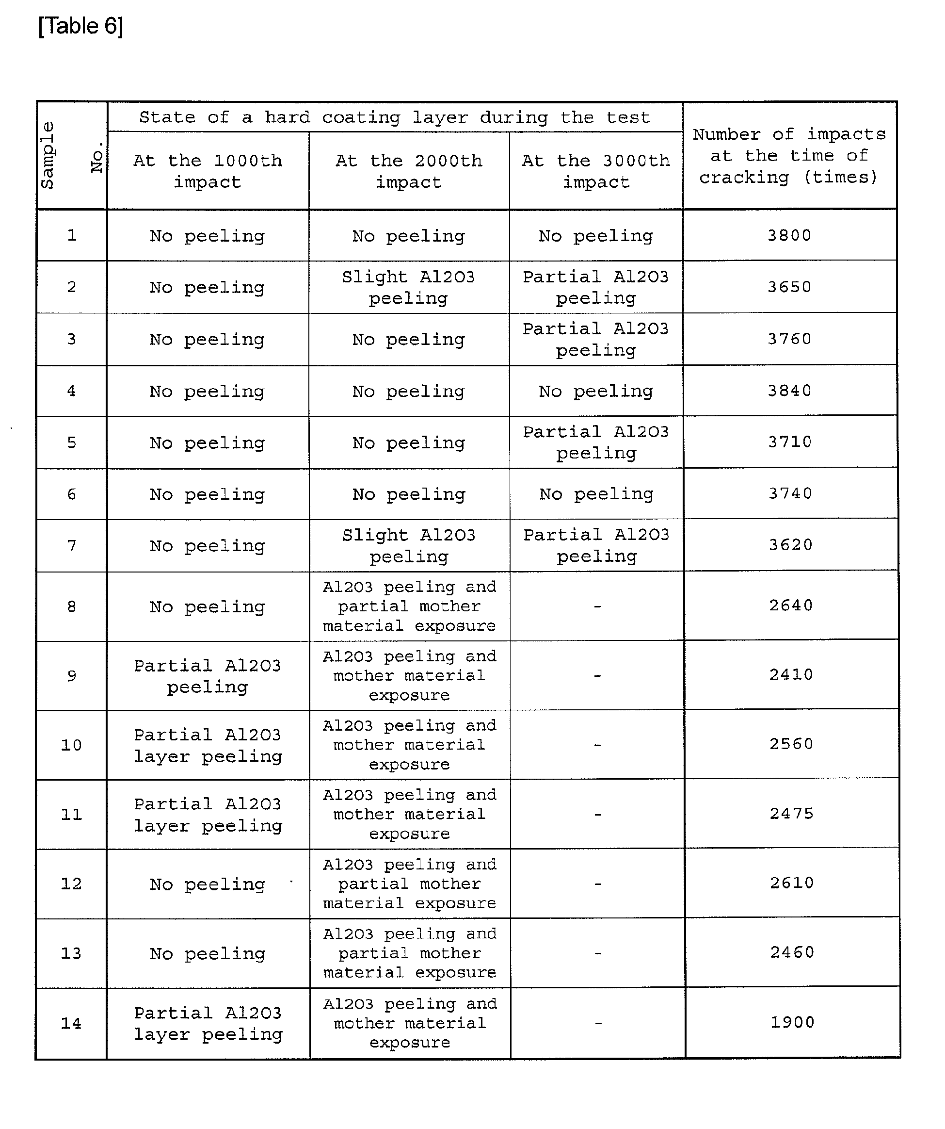
- Work material: Sleeve materials of ductile cast iron (FCD 700) with 8 grooves
- Cutting tool: CNMA120412
- Cutting speed: 250 m/min
- Feeding rate: 0.45 mm/rev
- Cutting depth: 1.5 mm
- Others: Using an aqueous cutting fluid
- Evaluation item: the number of impacts at the time of occurrence of cracking
- The results are shown in Tables 6 and 7
-
-

- On the other hand, in the sample Nos. 1 to 9 and sample Nos. 15 to 23 within the scope of the present invention and having the value of Δθz(hkl) in a range of -0.2 to 0.2, the peeling of the Al2O3 layer was suppressed in the cutting evaluation and thus the samples were found having excellent fracture resistance and cutting capability.
- The respective types of
coating layers 3 with the layer structures were formed for the cemented carbides subjected to the edge treatment (R-honing) of Example 1 in the coating formation condition by the CVD method as shown in Table 1 and Table 7. The obtained samples (30 to 33) were evaluated in the same manner as Example 1. The results are shown in Table 8 to 10. -

-

-
Table 10 Sample
No.State of a hard coating layer during the test Number of impacts at the time of cracking (times) At the 1000th impact At the 2000th impact At the 3000th impact 30 No peeling No peeling Partial Al2O3 peeling 3780 31 No peeling Slight Al2O3 peeling Partial Al2O3 peeling 3760 32 No peeling Slight Al2O3 peeling Partial Al2O3 peeling 3700 33 No peeling Slight Al2O3 peeling Partial Al2O3 peeling 3670 -
-
FIG. 1 shows an image of a main part of a surface-coatedmember 1 of one embodiment of the present invention by a scanning electron microscopic (SEM) photograph. -
FIG. 2 shows a scanning electron microscope (SEM) photographs of the peripheries of the interlayers of cross sections ofcoating layers 3 of the surface-coatedmember 1 of one embodiment of the present invention. -
FIG. 3 shows an image of a main part of thecoating layer 3 of one embodiment of the present invention by a field emission-transmission electron microscopic (FE-TEM) photograph. -
FIG. 4 shows a peak chart of x-ray diffraction intensity obtained for the surface-coated cutting tool of one embodiment of the present invention. -
Figs. 5A and 5B show partially magnified drawings ofFIG. 2 . -
FIG. 6 shows a peak chart of x-ray diffraction intensity obtained for the surface-coated cutting tool of another embodiment of the present invention. -
- 1.
- Surface-coated member
- 2.
- Substrate
- 3.
- Coating layer
- 4.
- Titanium carbonitride layer
- 5.
- Interlayer
- 7.
- Undercoat layer
- 9.
- α-type Al2O3 layer
- 10.
- Surface layer
Claims (9)
- A surface-coated member provided with a coating layer having a layered body formed by successively bonding a titanium carbonitride (TiCN) layer; an interlayer containing titanium, aluminum, carbon, and oxygen, having an average thickness of 0.5 to 30 nm, and existing without disconnection; and an aluminum oxide (Al2O3) layer including an aluminum oxide (Al2O3) with the α-type crystal structure on the surface of a substrate.
- The surface-coated member according to claim 1, wherein an oxygen content in the center of the interlayer in the thickness direction is 15 to 40% by atom.
- The surface-coated member according to claim 1, wherein with respect to the diffraction peaks of x-ray diffraction analysis for the surface-coated member, in the case where θt is defined as the 2θ value of a diffraction peak attributed to the (200) plane of TiCN; θt0 is defined as the 2θ value of a diffraction peak attributed to the (200) plane of TiCN described in JCPDS card; θa(hkl) is defined as the 2θ value of a diffraction peak attributed to the (012), (104), (110), and (113) planes of the α-type crystal structure of Al2O3 (wherein, (hkl) is one of (012), (104), (110), and (113)); and θa0(hkl) is defined as the 2θ value of a diffraction peak attributed to the (012), (104), (110), and (113) planes of the α-type crystal structure of Al2O3 described in JCPDS card (wherein, (hkl) is one of (012), (104), (110), and (113)); the difference of Δθz(hkl) (= θt - θa(hkl) (wherein (hkl) is one of (012), (104), (110), and (113)) between the difference Δθt (= θt - θt0) of θt and θt0 and the difference of Δθa(hkl) (= θa(hkl) - θa0(hkl)) of θa(hkl) and θa0(hkl) of (012), (104), (110), and (113) planes is all in a range of -0.2° to 0.2°.
- The surface-coated member according to claim 3, wherein Δθz(012) for the (012) plane is in a range of -0.2° to 0°.
- The surface-coated member according to one of claims 1 to 4, wherein if the difference of θa(012) and θa0(012) is corrected to be zero, θa(116) appears at a lower angle than θa0(116).
- The surface-coated member according to claim 5, wherein θa(116) appears in the higher angle side by 31.8° to 31.9° than θa(012).
- The surface-coated member according to claim 5 or 6, wherein θa(104), θa(110), θa(113), and θa(024) appear in the higher angle side than the θa0(104), θa0(110), θa0(113), and θa0(024), respectively.
- The surface-coated member according to one of claims 5 to 7, wherein the α-type aluminum oxide layer is made of columnar crystals extended along the thickness direction.
- A cutting tool provided with the surface-coated member according to one of claims 1 to 7.
Applications Claiming Priority (4)
| Application Number | Priority Date | Filing Date | Title |
|---|---|---|---|
| JP2008045559 | 2008-02-27 | ||
| JP2008083955 | 2008-03-27 | ||
| JP2008113490 | 2008-04-24 | ||
| PCT/JP2009/053389 WO2009107648A1 (en) | 2008-02-27 | 2009-02-25 | Surface coated member and cutting tool |
Publications (3)
| Publication Number | Publication Date |
|---|---|
| EP2251122A1 true EP2251122A1 (en) | 2010-11-17 |
| EP2251122A4 EP2251122A4 (en) | 2014-07-30 |
| EP2251122B1 EP2251122B1 (en) | 2016-04-13 |
Family
ID=41016037
Family Applications (1)
| Application Number | Title | Priority Date | Filing Date |
|---|---|---|---|
| EP09714933.0A Active EP2251122B1 (en) | 2008-02-27 | 2009-02-25 | Surface coated member and cutting tool |
Country Status (5)
| Country | Link |
|---|---|
| US (1) | US8449992B2 (en) |
| EP (1) | EP2251122B1 (en) |
| JP (2) | JP5111600B2 (en) |
| CN (1) | CN101959631B (en) |
| WO (1) | WO2009107648A1 (en) |
Cited By (4)
| Publication number | Priority date | Publication date | Assignee | Title |
|---|---|---|---|---|
| EP2604720A1 (en) * | 2011-12-14 | 2013-06-19 | Sandvik Intellectual Property Ab | Coated cutting tool and method of manufacturing the same |
| CN105705281A (en) * | 2013-11-08 | 2016-06-22 | 株式会社图格莱 | Coated cutting tool |
| EP3124144A4 (en) * | 2014-03-22 | 2017-10-25 | KYOCERA Corporation | Coated tool and cutting tool |
| EP3318660A1 (en) * | 2016-11-02 | 2018-05-09 | Tungaloy Corporation | Coated cutting tool |
Families Citing this family (30)
| Publication number | Priority date | Publication date | Assignee | Title |
|---|---|---|---|---|
| DE102009001675A1 (en) * | 2009-03-19 | 2010-09-23 | Eberhard-Karls-Universität Tübingen | cutting tool |
| KR101395625B1 (en) * | 2009-11-06 | 2014-05-16 | 가부시키가이샤 탕가로이 | Coated tool |
| JP2011152602A (en) * | 2010-01-27 | 2011-08-11 | Mitsubishi Materials Corp | Surface-coated cutting tool provided with hard coated layer demonstrating superior chipping resistance |
| JP5693039B2 (en) * | 2010-04-27 | 2015-04-01 | 京セラ株式会社 | Surface covering member |
| JP5472529B2 (en) * | 2011-03-31 | 2014-04-16 | 日立ツール株式会社 | Hard film coating member and blade-tip-exchange-type rotary tool having the same |
| JP5153968B2 (en) * | 2011-04-28 | 2013-02-27 | 京セラ株式会社 | Cutting tools |
| US8524360B2 (en) | 2011-08-29 | 2013-09-03 | Kennametal Inc. | Cutting insert with a titanium oxycarbonitride coating and method for making the same |
| ES2567039T5 (en) * | 2011-09-16 | 2019-07-03 | Walter Ag | Alpha alumina coated cutting tool containing sulfur |
| CN103084598A (en) * | 2011-10-31 | 2013-05-08 | 三菱综合材料株式会社 | Surface coating cutting tool with hard coating layer playing excellent fracture resistance |
| CN103128325A (en) * | 2011-11-30 | 2013-06-05 | 三菱综合材料株式会社 | Surface-coated cutting tool in which hard coating layer demonstrates excellent chipping resistance |
| JP5838789B2 (en) * | 2011-12-22 | 2016-01-06 | 三菱マテリアル株式会社 | Surface coated cutting tool whose hard coating layer exhibits excellent chipping resistance in high-speed intermittent cutting |
| JP5850402B2 (en) * | 2012-02-16 | 2016-02-03 | 三菱マテリアル株式会社 | Surface coated cutting tool with excellent chipping resistance due to hard coating layer |
| DE112013003182B4 (en) | 2012-06-29 | 2022-05-25 | Sumitomo Electric Hardmetal Corp. | Surface coated cutting tool |
| JP5892473B2 (en) * | 2012-09-13 | 2016-03-23 | 三菱マテリアル株式会社 | A surface-coated cutting tool with a hard coating layer that exhibits excellent peeling and chipping resistance in high-speed intermittent cutting. |
| CN104703734B (en) * | 2012-10-01 | 2016-08-24 | 日立工具股份有限公司 | Hard film-coated tool and manufacture method thereof |
| WO2014096351A1 (en) * | 2012-12-21 | 2014-06-26 | Sandvik Intellectual Property Ab | Coated cutting tool and method for manufacturing the same |
| US9371580B2 (en) | 2013-03-21 | 2016-06-21 | Kennametal Inc. | Coated body wherein the coating scheme includes a coating layer of TiAl2O3 and method of making the same |
| USRE49475E1 (en) * | 2013-06-14 | 2023-03-28 | Sandvik Intellectual Property Ab | Coated cutting tool |
| JP5902865B2 (en) * | 2013-08-27 | 2016-04-13 | 京セラ株式会社 | Coated tool |
| KR101536462B1 (en) | 2013-12-23 | 2015-07-24 | 한국야금 주식회사 | Coated film for cutting tools for machining hrsa and cast iron |
| KR101843453B1 (en) * | 2014-01-27 | 2018-03-29 | 가부시키가이샤 탕가로이 | Coated Cutting Tool |
| US9719175B2 (en) | 2014-09-30 | 2017-08-01 | Kennametal Inc. | Multilayer structured coatings for cutting tools |
| RU2704949C2 (en) * | 2014-12-19 | 2019-10-31 | Сандвик Интеллекчуал Проперти Аб | Cvd coated cutting tool |
| US10640868B2 (en) * | 2015-04-27 | 2020-05-05 | Kyocera Corporation | Coated member |
| CN106856660B (en) * | 2015-10-09 | 2019-05-28 | 住友电工硬质合金株式会社 | Surface-coated cutting tool |
| DE112016005414B4 (en) * | 2015-11-28 | 2023-12-07 | Kyocera Corporation | CUTTING TOOL |
| JPWO2018105403A1 (en) * | 2016-12-09 | 2019-10-24 | 住友電工ハードメタル株式会社 | Surface coated cutting tool |
| JP6703311B2 (en) | 2018-01-26 | 2020-06-03 | 株式会社タンガロイ | Coated cutting tools |
| JP6999585B2 (en) * | 2019-01-18 | 2022-01-18 | 株式会社タンガロイ | Cover cutting tool |
| JP7055761B2 (en) * | 2019-02-15 | 2022-04-18 | 株式会社タンガロイ | Cover cutting tool |
Citations (3)
| Publication number | Priority date | Publication date | Assignee | Title |
|---|---|---|---|---|
| EP1464727A2 (en) * | 2003-04-01 | 2004-10-06 | Sandvik AB | Oxide coated cutting tool |
| JP2006055950A (en) * | 2004-08-20 | 2006-03-02 | Tungaloy Corp | Coated cutting tool |
| EP1655392A1 (en) * | 2004-11-05 | 2006-05-10 | Seco Tools Ab | Alumina layer with enhanced texture |
Family Cites Families (14)
| Publication number | Priority date | Publication date | Assignee | Title |
|---|---|---|---|---|
| JPH0780083B2 (en) * | 1986-09-30 | 1995-08-30 | 三菱マテリアル株式会社 | Surface coated hard alloy cutting tool with stable service life |
| SE501527C2 (en) * | 1992-12-18 | 1995-03-06 | Sandvik Ab | Methods and articles when coating a cutting tool with an alumina layer |
| JP3236903B2 (en) | 1993-10-13 | 2001-12-10 | 三菱マテリアル株式会社 | Surface coated cutting tool |
| US5920760A (en) * | 1994-05-31 | 1999-07-06 | Mitsubishi Materials Corporation | Coated hard alloy blade member |
| JPH10237649A (en) * | 1997-02-20 | 1998-09-08 | Mitsubishi Materials Corp | Surface coated cutting tool excellent in chipping resistance |
| JPH1177407A (en) | 1997-09-04 | 1999-03-23 | Hitachi Metals Ltd | Tool coated with aluminum oxide |
| JP2003025114A (en) | 2001-07-16 | 2003-01-29 | Toshiba Tungaloy Co Ltd | Aluminium oxide coated cutting tool |
| JP3578121B2 (en) * | 2001-08-06 | 2004-10-20 | 三菱マテリアル神戸ツールズ株式会社 | Surface-coated cemented carbide cutting tool with excellent heat-resistant plastic deformation with wear-resistant coating layer |
| SE525581C2 (en) * | 2002-05-08 | 2005-03-15 | Seco Tools Ab | Cutting coated with alumina made with CVD |
| JP3971293B2 (en) | 2002-08-08 | 2007-09-05 | 株式会社神戸製鋼所 | Laminated film excellent in wear resistance and heat resistance, production method thereof, and multilayer film coated tool excellent in wear resistance and heat resistance |
| SE526602C2 (en) * | 2003-10-27 | 2005-10-18 | Seco Tools Ab | Coated cutting for rough turning |
| US7455918B2 (en) * | 2004-03-12 | 2008-11-25 | Kennametal Inc. | Alumina coating, coated product and method of making the same |
| SE528430C2 (en) * | 2004-11-05 | 2006-11-14 | Seco Tools Ab | With aluminum oxide coated cutting tool inserts and method of making this |
| SE529051C2 (en) * | 2005-09-27 | 2007-04-17 | Seco Tools Ab | Cutting tool inserts coated with alumina |
-
2009
- 2009-02-25 EP EP09714933.0A patent/EP2251122B1/en active Active
- 2009-02-25 US US12/919,740 patent/US8449992B2/en active Active
- 2009-02-25 WO PCT/JP2009/053389 patent/WO2009107648A1/en active Application Filing
- 2009-02-25 JP JP2010500710A patent/JP5111600B2/en active Active
- 2009-02-25 CN CN200980106446XA patent/CN101959631B/en active Active
-
2012
- 2012-07-27 JP JP2012166460A patent/JP5460790B2/en active Active
Patent Citations (3)
| Publication number | Priority date | Publication date | Assignee | Title |
|---|---|---|---|---|
| EP1464727A2 (en) * | 2003-04-01 | 2004-10-06 | Sandvik AB | Oxide coated cutting tool |
| JP2006055950A (en) * | 2004-08-20 | 2006-03-02 | Tungaloy Corp | Coated cutting tool |
| EP1655392A1 (en) * | 2004-11-05 | 2006-05-10 | Seco Tools Ab | Alumina layer with enhanced texture |
Non-Patent Citations (1)
| Title |
|---|
| See also references of WO2009107648A1 * |
Cited By (9)
| Publication number | Priority date | Publication date | Assignee | Title |
|---|---|---|---|---|
| EP2604720A1 (en) * | 2011-12-14 | 2013-06-19 | Sandvik Intellectual Property Ab | Coated cutting tool and method of manufacturing the same |
| KR20140105754A (en) * | 2011-12-14 | 2014-09-02 | 산드빅 인터렉츄얼 프로퍼티 에이비 | Coated cutting tool and method of manufacturing the same |
| JP2015500148A (en) * | 2011-12-14 | 2015-01-05 | サンドビック インテレクチュアル プロパティー アクティエボラーグ | Coated cutting tool and manufacturing method thereof |
| US9945029B2 (en) | 2011-12-14 | 2018-04-17 | Sandvik Intellectual Property Ab | Coated cutting tool and method of manufacturing the same |
| CN105705281A (en) * | 2013-11-08 | 2016-06-22 | 株式会社图格莱 | Coated cutting tool |
| EP3067133A4 (en) * | 2013-11-08 | 2017-01-18 | Tungaloy Corporation | Coated cutting tool |
| CN105705281B (en) * | 2013-11-08 | 2017-08-15 | 株式会社泰珂洛 | Coated cutting tool |
| EP3124144A4 (en) * | 2014-03-22 | 2017-10-25 | KYOCERA Corporation | Coated tool and cutting tool |
| EP3318660A1 (en) * | 2016-11-02 | 2018-05-09 | Tungaloy Corporation | Coated cutting tool |
Also Published As
| Publication number | Publication date |
|---|---|
| JP2012254523A (en) | 2012-12-27 |
| WO2009107648A1 (en) | 2009-09-03 |
| US20100330360A1 (en) | 2010-12-30 |
| CN101959631A (en) | 2011-01-26 |
| US8449992B2 (en) | 2013-05-28 |
| EP2251122A4 (en) | 2014-07-30 |
| EP2251122B1 (en) | 2016-04-13 |
| JP5460790B2 (en) | 2014-04-02 |
| CN101959631B (en) | 2012-09-26 |
| JP5111600B2 (en) | 2013-01-09 |
| JPWO2009107648A1 (en) | 2011-07-07 |
Similar Documents
| Publication | Publication Date | Title |
|---|---|---|
| EP2251122B1 (en) | Surface coated member and cutting tool | |
| EP2006040B1 (en) | Cutting tool, method for producing same and cutting method | |
| JP4832108B2 (en) | Surface coated cutting tool | |
| EP3747575B1 (en) | Coated tool, and cutting tool comprising same | |
| JP2007260851A (en) | Surface coated cutting tool | |
| KR102312226B1 (en) | Surface-coated cutting tool and method of producing the same | |
| WO2017217012A1 (en) | Surface-coated cutting tool | |
| WO2011052767A1 (en) | Surface coated cutting tool with excellent chip resistance | |
| CN110799293B (en) | Coated cutting tool, and method for manufacturing cut product | |
| JP4351521B2 (en) | Surface coated cutting tool | |
| JP2004291162A (en) | Surface coated cutting tool | |
| JP4936742B2 (en) | Surface coating tools and cutting tools | |
| JP4817799B2 (en) | Surface covering | |
| EP3747577B1 (en) | Coated tool and cutting tool comprising said coated tool | |
| JP4663248B2 (en) | Surface coated cutting tool | |
| CN113165083B (en) | Coated cutting tool and cutting tool provided with same | |
| WO2021245784A1 (en) | Cutting tool | |
| EP3747576A1 (en) | Coated tool, and cutting tool comprising same | |
| JP4484500B2 (en) | Surface coated cutting tool | |
| JP4936741B2 (en) | Surface coating tools and cutting tools | |
| KR20220024673A (en) | Coated tool and cutting tool having same | |
| CN113165082A (en) | Coated cutting tool and cutting tool with same |
Legal Events
| Date | Code | Title | Description |
|---|---|---|---|
| PUAI | Public reference made under article 153(3) epc to a published international application that has entered the european phase |
Free format text: ORIGINAL CODE: 0009012 |
|
| 17P | Request for examination filed |
Effective date: 20100901 |
|
| AK | Designated contracting states |
Kind code of ref document: A1 Designated state(s): AT BE BG CH CY CZ DE DK EE ES FI FR GB GR HR HU IE IS IT LI LT LU LV MC MK MT NL NO PL PT RO SE SI SK TR |
|
| AX | Request for extension of the european patent |
Extension state: AL BA RS |
|
| DAX | Request for extension of the european patent (deleted) | ||
| A4 | Supplementary search report drawn up and despatched |
Effective date: 20140630 |
|
| RIC1 | Information provided on ipc code assigned before grant |
Ipc: B23B 27/14 20060101AFI20140624BHEP Ipc: C23C 16/36 20060101ALI20140624BHEP Ipc: C23C 28/00 20060101ALI20140624BHEP Ipc: C23C 28/02 20060101ALI20140624BHEP |
|
| 17Q | First examination report despatched |
Effective date: 20150423 |
|
| GRAP | Despatch of communication of intention to grant a patent |
Free format text: ORIGINAL CODE: EPIDOSNIGR1 |
|
| INTG | Intention to grant announced |
Effective date: 20151001 |
|
| GRAS | Grant fee paid |
Free format text: ORIGINAL CODE: EPIDOSNIGR3 |
|
| GRAA | (expected) grant |
Free format text: ORIGINAL CODE: 0009210 |
|
| AK | Designated contracting states |
Kind code of ref document: B1 Designated state(s): AT BE BG CH CY CZ DE DK EE ES FI FR GB GR HR HU IE IS IT LI LT LU LV MC MK MT NL NO PL PT RO SE SI SK TR |
|
| REG | Reference to a national code |
Ref country code: GB Ref legal event code: FG4D |
|
| REG | Reference to a national code |
Ref country code: AT Ref legal event code: REF Ref document number: 789576 Country of ref document: AT Kind code of ref document: T Effective date: 20160415 Ref country code: CH Ref legal event code: EP |
|
| REG | Reference to a national code |
Ref country code: IE Ref legal event code: FG4D |
|
| REG | Reference to a national code |
Ref country code: DE Ref legal event code: R096 Ref document number: 602009037747 Country of ref document: DE |
|
| REG | Reference to a national code |
Ref country code: LT Ref legal event code: MG4D |
|
| REG | Reference to a national code |
Ref country code: AT Ref legal event code: MK05 Ref document number: 789576 Country of ref document: AT Kind code of ref document: T Effective date: 20160413 |
|
| REG | Reference to a national code |
Ref country code: NL Ref legal event code: MP Effective date: 20160413 |
|
| PG25 | Lapsed in a contracting state [announced via postgrant information from national office to epo] |
Ref country code: FI Free format text: LAPSE BECAUSE OF FAILURE TO SUBMIT A TRANSLATION OF THE DESCRIPTION OR TO PAY THE FEE WITHIN THE PRESCRIBED TIME-LIMIT Effective date: 20160413 Ref country code: LT Free format text: LAPSE BECAUSE OF FAILURE TO SUBMIT A TRANSLATION OF THE DESCRIPTION OR TO PAY THE FEE WITHIN THE PRESCRIBED TIME-LIMIT Effective date: 20160413 Ref country code: NL Free format text: LAPSE BECAUSE OF FAILURE TO SUBMIT A TRANSLATION OF THE DESCRIPTION OR TO PAY THE FEE WITHIN THE PRESCRIBED TIME-LIMIT Effective date: 20160413 Ref country code: PL Free format text: LAPSE BECAUSE OF FAILURE TO SUBMIT A TRANSLATION OF THE DESCRIPTION OR TO PAY THE FEE WITHIN THE PRESCRIBED TIME-LIMIT Effective date: 20160413 Ref country code: NO Free format text: LAPSE BECAUSE OF FAILURE TO SUBMIT A TRANSLATION OF THE DESCRIPTION OR TO PAY THE FEE WITHIN THE PRESCRIBED TIME-LIMIT Effective date: 20160713 |
|
| PG25 | Lapsed in a contracting state [announced via postgrant information from national office to epo] |
Ref country code: PT Free format text: LAPSE BECAUSE OF FAILURE TO SUBMIT A TRANSLATION OF THE DESCRIPTION OR TO PAY THE FEE WITHIN THE PRESCRIBED TIME-LIMIT Effective date: 20160816 Ref country code: GR Free format text: LAPSE BECAUSE OF FAILURE TO SUBMIT A TRANSLATION OF THE DESCRIPTION OR TO PAY THE FEE WITHIN THE PRESCRIBED TIME-LIMIT Effective date: 20160714 Ref country code: SE Free format text: LAPSE BECAUSE OF FAILURE TO SUBMIT A TRANSLATION OF THE DESCRIPTION OR TO PAY THE FEE WITHIN THE PRESCRIBED TIME-LIMIT Effective date: 20160413 Ref country code: HR Free format text: LAPSE BECAUSE OF FAILURE TO SUBMIT A TRANSLATION OF THE DESCRIPTION OR TO PAY THE FEE WITHIN THE PRESCRIBED TIME-LIMIT Effective date: 20160413 Ref country code: LV Free format text: LAPSE BECAUSE OF FAILURE TO SUBMIT A TRANSLATION OF THE DESCRIPTION OR TO PAY THE FEE WITHIN THE PRESCRIBED TIME-LIMIT Effective date: 20160413 Ref country code: ES Free format text: LAPSE BECAUSE OF FAILURE TO SUBMIT A TRANSLATION OF THE DESCRIPTION OR TO PAY THE FEE WITHIN THE PRESCRIBED TIME-LIMIT Effective date: 20160413 Ref country code: AT Free format text: LAPSE BECAUSE OF FAILURE TO SUBMIT A TRANSLATION OF THE DESCRIPTION OR TO PAY THE FEE WITHIN THE PRESCRIBED TIME-LIMIT Effective date: 20160413 |
|
| PG25 | Lapsed in a contracting state [announced via postgrant information from national office to epo] |
Ref country code: BE Free format text: LAPSE BECAUSE OF FAILURE TO SUBMIT A TRANSLATION OF THE DESCRIPTION OR TO PAY THE FEE WITHIN THE PRESCRIBED TIME-LIMIT Effective date: 20160413 Ref country code: IT Free format text: LAPSE BECAUSE OF FAILURE TO SUBMIT A TRANSLATION OF THE DESCRIPTION OR TO PAY THE FEE WITHIN THE PRESCRIBED TIME-LIMIT Effective date: 20160413 |
|
| REG | Reference to a national code |
Ref country code: DE Ref legal event code: R097 Ref document number: 602009037747 Country of ref document: DE |
|
| PG25 | Lapsed in a contracting state [announced via postgrant information from national office to epo] |
Ref country code: CZ Free format text: LAPSE BECAUSE OF FAILURE TO SUBMIT A TRANSLATION OF THE DESCRIPTION OR TO PAY THE FEE WITHIN THE PRESCRIBED TIME-LIMIT Effective date: 20160413 Ref country code: RO Free format text: LAPSE BECAUSE OF FAILURE TO SUBMIT A TRANSLATION OF THE DESCRIPTION OR TO PAY THE FEE WITHIN THE PRESCRIBED TIME-LIMIT Effective date: 20160413 Ref country code: SK Free format text: LAPSE BECAUSE OF FAILURE TO SUBMIT A TRANSLATION OF THE DESCRIPTION OR TO PAY THE FEE WITHIN THE PRESCRIBED TIME-LIMIT Effective date: 20160413 Ref country code: DK Free format text: LAPSE BECAUSE OF FAILURE TO SUBMIT A TRANSLATION OF THE DESCRIPTION OR TO PAY THE FEE WITHIN THE PRESCRIBED TIME-LIMIT Effective date: 20160413 Ref country code: EE Free format text: LAPSE BECAUSE OF FAILURE TO SUBMIT A TRANSLATION OF THE DESCRIPTION OR TO PAY THE FEE WITHIN THE PRESCRIBED TIME-LIMIT Effective date: 20160413 |
|
| PLBE | No opposition filed within time limit |
Free format text: ORIGINAL CODE: 0009261 |
|
| STAA | Information on the status of an ep patent application or granted ep patent |
Free format text: STATUS: NO OPPOSITION FILED WITHIN TIME LIMIT |
|
| 26N | No opposition filed |
Effective date: 20170116 |
|
| PG25 | Lapsed in a contracting state [announced via postgrant information from national office to epo] |
Ref country code: SI Free format text: LAPSE BECAUSE OF FAILURE TO SUBMIT A TRANSLATION OF THE DESCRIPTION OR TO PAY THE FEE WITHIN THE PRESCRIBED TIME-LIMIT Effective date: 20160413 |
|
| PG25 | Lapsed in a contracting state [announced via postgrant information from national office to epo] |
Ref country code: MC Free format text: LAPSE BECAUSE OF FAILURE TO SUBMIT A TRANSLATION OF THE DESCRIPTION OR TO PAY THE FEE WITHIN THE PRESCRIBED TIME-LIMIT Effective date: 20160413 |
|
| REG | Reference to a national code |
Ref country code: CH Ref legal event code: PL |
|
| GBPC | Gb: european patent ceased through non-payment of renewal fee |
Effective date: 20170225 |
|
| PG25 | Lapsed in a contracting state [announced via postgrant information from national office to epo] |
Ref country code: CH Free format text: LAPSE BECAUSE OF NON-PAYMENT OF DUE FEES Effective date: 20170228 Ref country code: LI Free format text: LAPSE BECAUSE OF NON-PAYMENT OF DUE FEES Effective date: 20170228 |
|
| REG | Reference to a national code |
Ref country code: IE Ref legal event code: MM4A |
|
| REG | Reference to a national code |
Ref country code: FR Ref legal event code: ST Effective date: 20171031 |
|
| PG25 | Lapsed in a contracting state [announced via postgrant information from national office to epo] |
Ref country code: LU Free format text: LAPSE BECAUSE OF NON-PAYMENT OF DUE FEES Effective date: 20170225 |
|
| PG25 | Lapsed in a contracting state [announced via postgrant information from national office to epo] |
Ref country code: FR Free format text: LAPSE BECAUSE OF NON-PAYMENT OF DUE FEES Effective date: 20170228 |
|
| PG25 | Lapsed in a contracting state [announced via postgrant information from national office to epo] |
Ref country code: IE Free format text: LAPSE BECAUSE OF NON-PAYMENT OF DUE FEES Effective date: 20170225 Ref country code: GB Free format text: LAPSE BECAUSE OF NON-PAYMENT OF DUE FEES Effective date: 20170225 |
|
| PG25 | Lapsed in a contracting state [announced via postgrant information from national office to epo] |
Ref country code: MT Free format text: LAPSE BECAUSE OF NON-PAYMENT OF DUE FEES Effective date: 20170225 |
|
| PG25 | Lapsed in a contracting state [announced via postgrant information from national office to epo] |
Ref country code: HU Free format text: LAPSE BECAUSE OF FAILURE TO SUBMIT A TRANSLATION OF THE DESCRIPTION OR TO PAY THE FEE WITHIN THE PRESCRIBED TIME-LIMIT; INVALID AB INITIO Effective date: 20090225 |
|
| PG25 | Lapsed in a contracting state [announced via postgrant information from national office to epo] |
Ref country code: BG Free format text: LAPSE BECAUSE OF FAILURE TO SUBMIT A TRANSLATION OF THE DESCRIPTION OR TO PAY THE FEE WITHIN THE PRESCRIBED TIME-LIMIT Effective date: 20160413 |
|
| PG25 | Lapsed in a contracting state [announced via postgrant information from national office to epo] |
Ref country code: CY Free format text: LAPSE BECAUSE OF NON-PAYMENT OF DUE FEES Effective date: 20160413 |
|
| PG25 | Lapsed in a contracting state [announced via postgrant information from national office to epo] |
Ref country code: MK Free format text: LAPSE BECAUSE OF FAILURE TO SUBMIT A TRANSLATION OF THE DESCRIPTION OR TO PAY THE FEE WITHIN THE PRESCRIBED TIME-LIMIT Effective date: 20160413 |
|
| PG25 | Lapsed in a contracting state [announced via postgrant information from national office to epo] |
Ref country code: TR Free format text: LAPSE BECAUSE OF FAILURE TO SUBMIT A TRANSLATION OF THE DESCRIPTION OR TO PAY THE FEE WITHIN THE PRESCRIBED TIME-LIMIT Effective date: 20160413 |
|
| PG25 | Lapsed in a contracting state [announced via postgrant information from national office to epo] |
Ref country code: IS Free format text: LAPSE BECAUSE OF FAILURE TO SUBMIT A TRANSLATION OF THE DESCRIPTION OR TO PAY THE FEE WITHIN THE PRESCRIBED TIME-LIMIT Effective date: 20160813 |
|
| PGFP | Annual fee paid to national office [announced via postgrant information from national office to epo] |
Ref country code: DE Payment date: 20221230 Year of fee payment: 15 |
|
| P01 | Opt-out of the competence of the unified patent court (upc) registered |
Effective date: 20230505 |